EP2118967B1 - Uv-lampe zur verwendung für wasserreinigungsfilter - Google Patents
Uv-lampe zur verwendung für wasserreinigungsfilter Download PDFInfo
- Publication number
- EP2118967B1 EP2118967B1 EP08730003.4A EP08730003A EP2118967B1 EP 2118967 B1 EP2118967 B1 EP 2118967B1 EP 08730003 A EP08730003 A EP 08730003A EP 2118967 B1 EP2118967 B1 EP 2118967B1
- Authority
- EP
- European Patent Office
- Prior art keywords
- step portion
- socket
- lamp base
- end surface
- connector
- Prior art date
- Legal status (The legal status is an assumption and is not a legal conclusion. Google has not performed a legal analysis and makes no representation as to the accuracy of the status listed.)
- Active
Links
Images


Classifications
-
- C—CHEMISTRY; METALLURGY
- C02—TREATMENT OF WATER, WASTE WATER, SEWAGE, OR SLUDGE
- C02F—TREATMENT OF WATER, WASTE WATER, SEWAGE, OR SLUDGE
- C02F1/00—Treatment of water, waste water, or sewage
- C02F1/30—Treatment of water, waste water, or sewage by irradiation
- C02F1/32—Treatment of water, waste water, or sewage by irradiation with ultraviolet light
- C02F1/325—Irradiation devices or lamp constructions
-
- A—HUMAN NECESSITIES
- A61—MEDICAL OR VETERINARY SCIENCE; HYGIENE
- A61L—METHODS OR APPARATUS FOR STERILISING MATERIALS OR OBJECTS IN GENERAL; DISINFECTION, STERILISATION OR DEODORISATION OF AIR; CHEMICAL ASPECTS OF BANDAGES, DRESSINGS, ABSORBENT PADS OR SURGICAL ARTICLES; MATERIALS FOR BANDAGES, DRESSINGS, ABSORBENT PADS OR SURGICAL ARTICLES
- A61L9/00—Disinfection, sterilisation or deodorisation of air
- A61L9/16—Disinfection, sterilisation or deodorisation of air using physical phenomena
- A61L9/18—Radiation
- A61L9/20—Ultraviolet radiation
-
- H—ELECTRICITY
- H01—ELECTRIC ELEMENTS
- H01J—ELECTRIC DISCHARGE TUBES OR DISCHARGE LAMPS
- H01J5/00—Details relating to vessels or to leading-in conductors common to two or more basic types of discharge tubes or lamps
- H01J5/50—Means forming part of the tube or lamps for the purpose of providing electrical connection to it
- H01J5/54—Means forming part of the tube or lamps for the purpose of providing electrical connection to it supported by a separate part, e.g. base
- H01J5/56—Shape of the separate part
-
- H—ELECTRICITY
- H01—ELECTRIC ELEMENTS
- H01R—ELECTRICALLY-CONDUCTIVE CONNECTIONS; STRUCTURAL ASSOCIATIONS OF A PLURALITY OF MUTUALLY-INSULATED ELECTRICAL CONNECTING ELEMENTS; COUPLING DEVICES; CURRENT COLLECTORS
- H01R13/00—Details of coupling devices of the kinds covered by groups H01R12/70 or H01R24/00 - H01R33/00
- H01R13/46—Bases; Cases
- H01R13/52—Dustproof, splashproof, drip-proof, waterproof, or flameproof cases
- H01R13/523—Dustproof, splashproof, drip-proof, waterproof, or flameproof cases for use under water
-
- H—ELECTRICITY
- H01—ELECTRIC ELEMENTS
- H01R—ELECTRICALLY-CONDUCTIVE CONNECTIONS; STRUCTURAL ASSOCIATIONS OF A PLURALITY OF MUTUALLY-INSULATED ELECTRICAL CONNECTING ELEMENTS; COUPLING DEVICES; CURRENT COLLECTORS
- H01R13/00—Details of coupling devices of the kinds covered by groups H01R12/70 or H01R24/00 - H01R33/00
- H01R13/66—Structural association with built-in electrical component
- H01R13/665—Structural association with built-in electrical component with built-in electronic circuit
- H01R13/6666—Structural association with built-in electrical component with built-in electronic circuit with built-in overvoltage protection
-
- H—ELECTRICITY
- H01—ELECTRIC ELEMENTS
- H01R—ELECTRICALLY-CONDUCTIVE CONNECTIONS; STRUCTURAL ASSOCIATIONS OF A PLURALITY OF MUTUALLY-INSULATED ELECTRICAL CONNECTING ELEMENTS; COUPLING DEVICES; CURRENT COLLECTORS
- H01R13/00—Details of coupling devices of the kinds covered by groups H01R12/70 or H01R24/00 - H01R33/00
- H01R13/66—Structural association with built-in electrical component
- H01R13/70—Structural association with built-in electrical component with built-in switch
-
- H—ELECTRICITY
- H01—ELECTRIC ELEMENTS
- H01R—ELECTRICALLY-CONDUCTIVE CONNECTIONS; STRUCTURAL ASSOCIATIONS OF A PLURALITY OF MUTUALLY-INSULATED ELECTRICAL CONNECTING ELEMENTS; COUPLING DEVICES; CURRENT COLLECTORS
- H01R25/00—Coupling parts adapted for simultaneous co-operation with two or more identical counterparts, e.g. for distributing energy to two or more circuits
- H01R25/003—Coupling parts adapted for simultaneous co-operation with two or more identical counterparts, e.g. for distributing energy to two or more circuits the coupling part being secured only to wires or cables
-
- H—ELECTRICITY
- H01—ELECTRIC ELEMENTS
- H01R—ELECTRICALLY-CONDUCTIVE CONNECTIONS; STRUCTURAL ASSOCIATIONS OF A PLURALITY OF MUTUALLY-INSULATED ELECTRICAL CONNECTING ELEMENTS; COUPLING DEVICES; CURRENT COLLECTORS
- H01R31/00—Coupling parts supported only by co-operation with counterpart
- H01R31/06—Intermediate parts for linking two coupling parts, e.g. adapter
-
- H—ELECTRICITY
- H01—ELECTRIC ELEMENTS
- H01R—ELECTRICALLY-CONDUCTIVE CONNECTIONS; STRUCTURAL ASSOCIATIONS OF A PLURALITY OF MUTUALLY-INSULATED ELECTRICAL CONNECTING ELEMENTS; COUPLING DEVICES; CURRENT COLLECTORS
- H01R33/00—Coupling devices specially adapted for supporting apparatus and having one part acting as a holder providing support and electrical connection via a counterpart which is structurally associated with the apparatus, e.g. lamp holders; Separate parts thereof
- H01R33/05—Two-pole devices
- H01R33/06—Two-pole devices with two current-carrying pins, blades or analogous contacts, having their axes parallel to each other
- H01R33/08—Two-pole devices with two current-carrying pins, blades or analogous contacts, having their axes parallel to each other for supporting tubular fluorescent lamp
- H01R33/0836—Two-pole devices with two current-carrying pins, blades or analogous contacts, having their axes parallel to each other for supporting tubular fluorescent lamp characterised by the lamp holding means
-
- H—ELECTRICITY
- H01—ELECTRIC ELEMENTS
- H01R—ELECTRICALLY-CONDUCTIVE CONNECTIONS; STRUCTURAL ASSOCIATIONS OF A PLURALITY OF MUTUALLY-INSULATED ELECTRICAL CONNECTING ELEMENTS; COUPLING DEVICES; CURRENT COLLECTORS
- H01R33/00—Coupling devices specially adapted for supporting apparatus and having one part acting as a holder providing support and electrical connection via a counterpart which is structurally associated with the apparatus, e.g. lamp holders; Separate parts thereof
- H01R33/05—Two-pole devices
- H01R33/22—Two-pole devices for screw type base, e.g. for lamp
-
- B—PERFORMING OPERATIONS; TRANSPORTING
- B01—PHYSICAL OR CHEMICAL PROCESSES OR APPARATUS IN GENERAL
- B01D—SEPARATION
- B01D2259/00—Type of treatment
- B01D2259/80—Employing electric, magnetic, electromagnetic or wave energy, or particle radiation
- B01D2259/804—UV light
-
- C—CHEMISTRY; METALLURGY
- C02—TREATMENT OF WATER, WASTE WATER, SEWAGE, OR SLUDGE
- C02F—TREATMENT OF WATER, WASTE WATER, SEWAGE, OR SLUDGE
- C02F1/00—Treatment of water, waste water, or sewage
- C02F1/30—Treatment of water, waste water, or sewage by irradiation
- C02F1/32—Treatment of water, waste water, or sewage by irradiation with ultraviolet light
-
- C—CHEMISTRY; METALLURGY
- C02—TREATMENT OF WATER, WASTE WATER, SEWAGE, OR SLUDGE
- C02F—TREATMENT OF WATER, WASTE WATER, SEWAGE, OR SLUDGE
- C02F2201/00—Apparatus for treatment of water, waste water or sewage
- C02F2201/002—Construction details of the apparatus
- C02F2201/004—Seals, connections
-
- C—CHEMISTRY; METALLURGY
- C02—TREATMENT OF WATER, WASTE WATER, SEWAGE, OR SLUDGE
- C02F—TREATMENT OF WATER, WASTE WATER, SEWAGE, OR SLUDGE
- C02F2201/00—Apparatus for treatment of water, waste water or sewage
- C02F2201/32—Details relating to UV-irradiation devices
-
- H—ELECTRICITY
- H01—ELECTRIC ELEMENTS
- H01R—ELECTRICALLY-CONDUCTIVE CONNECTIONS; STRUCTURAL ASSOCIATIONS OF A PLURALITY OF MUTUALLY-INSULATED ELECTRICAL CONNECTING ELEMENTS; COUPLING DEVICES; CURRENT COLLECTORS
- H01R33/00—Coupling devices specially adapted for supporting apparatus and having one part acting as a holder providing support and electrical connection via a counterpart which is structurally associated with the apparatus, e.g. lamp holders; Separate parts thereof
- H01R33/05—Two-pole devices
- H01R33/06—Two-pole devices with two current-carrying pins, blades or analogous contacts, having their axes parallel to each other
- H01R33/08—Two-pole devices with two current-carrying pins, blades or analogous contacts, having their axes parallel to each other for supporting tubular fluorescent lamp
- H01R33/0809—Two-pole devices with two current-carrying pins, blades or analogous contacts, having their axes parallel to each other for supporting tubular fluorescent lamp having contacts on one side only
Definitions
- This invention generally relates to improvements in lamps, especially ultraviolet lamps used in air and water purifiers and disinfection units.
- Ultraviolet air and water or other liquid purifiers are known for disinfecting contaminated air or water or other liquid for domestic, industrial, municipal, or commercial use.
- Such purifiers include at least one lamp for emitting ultraviolet radiation installed into a chamber over which contaminated air or water or other liquid pass to kill microorganisms therein.
- the lamp includes two electrodes spaced apart within an elongated arc tube containing a gas, particularly noble gas with or without additives.
- a pair of end caps i.e., bases
- Each electrode contains two lead wires from the lamp seal each of which, or in some instances only one, are electrically connected to respective contact(s) or terminal pin(s).
- the lamp is typically inserted endwise into a sleeve installed in the water, other liquid or air purifier with or without the use of an external quartz sleeve.
- the pins are conveniently mounted on one of the end caps.
- WO2007/098163 A2 US 5 422 487 A , US 2006/186782 disclose a lamb base and a corresponding socket, having two stepped portions each providing a raised face, while pin connectors for electrical connections are provided in each of the raised faces.
- US 6,634,902 B1 discloses a lamb base and a corresponding socket according to the preamble of the independent claims.
- U.S. Patent 5,166,527 discloses a lamp, especially useful as an ultraviolet lamp for use in a water purifier, comprising an elongated, hollow arc tube extending along a longitudinal axis between opposite end regions.
- the tube contains a gas, preferably a noble gas with or without additives.
- a pair of electrodes is spaced apart along the longitudinal axis. The electrodes are respectively mounted within the arc tube at the end regions thereof.
- a pair of end caps is respectively mounted at the end regions of the arc tube.
- a first electrical contact or pair of electrical contacts or teiminal pins extends in mutual parallelism along the longitudinal axis and is electrically connected to one or both of the electrode lead wires.
- a second electrical contact or pair of electrical contacts or teiminal pins extends in mutual parallelism along the longitudinal axis and is electrically connected to one or both of the other of the electrode lead wires. Both pairs of pins are mounted on, and extend outwardly along the longitudinal axis of, one of the end caps.
- a wire conductor is, or two wire conductors are, located exteriorly of the tube and electrically connected to one pin or one pair of pins at one end region of the tube, as well as to the electrode at the other end region of the tube.
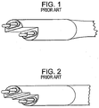
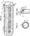
- FIG. 1 and 2 Two embodiments, of the lamp disclosed in the '527 patent are shown in prior art Figures 1 and 2 .
- the pairs of pins are offset relative to each other along the longitudinal axis. This offset resists the formation of an electrical arc between the pairs of pins exteriorly of the arc tube, especially in the presence of the moisture-laden, humid environment of the water purifier.
- the one end cap has a stepped outer end wall having a pair of wall portions lying in mutual parallelism in planes generally perpendicular to the longitudinal axis.
- the first pair of pins is supported on, and extends through, one of the end wall portions for a predetermined distance
- the second pair of pins is supported on, and extends through, the other of the end wall portions for the same predetermined distance.
- the planes of the end wall portions are spaced apart by a predetermined spacing larger than said predetermined distance in order to still further prevent electrical arcing between the pairs of pins exteriorly of the arc tube.
- a barrier wall internally of the one end cap physically separates the electrical connections to the two pairs of pins to resist the formation of an electrical arc between the pairs of pins interiorly of the one end cap.
- the barrier wall is advantageously made of the same non-conductive material as the one end cap.
- lamps There are many different types of lamps that have a base or end cap that can be connected with a socket to provide electrical connections to the lamps.
- the end cap and socket must be constructed to permit easy replacement of the lamp while securely holding the lamp. This may be particularly important in certain applications where vibration or movement of the lamp or lamp fixture could result in unintentional separation between the lamp's end cap and the socket. Additionally, the electrical connections must remain secure.
- the contact pins may become misaligned or bent due to their extension or projection from the base of the lamp, preventing their insertion into a socket. It may also be possible to insert the end cap into a socket such that the contacts are not connected with the proper terminals in the socket, resulting in improper operation of the lamp. Also, on a typical "slide into place" male/female pin connector there is no locking or twist locking and thus the pins may slide out and become disconnected easily by vibration for example.
- U.S. Patent 5,166,527 ('527), which uses a stepped base with pins connector, all of the contents of which are incorporated herein by reference.
- the '527 patent discloses a lamp or bulb, used as an ultraviolet lamp for use in an air or water purifier, comprising an elongated, hollow arc tube extending along a longitudinal axis between opposite end regions.
- the tube contains a gas, preferably a noble gas with or without additives.
- a pair of electrodes is spaced apart along the longitudinal axis.
- the electrodes are respectively mounted within the arc tube at the end regions thereof.
- a pair of end caps is respectively mounted at the end regions of the arc tube.
- a first electrical contact or pair of electrical contacts or terminal pins extends in mutual parallelism along the longitudinal axis and is electrically connected to one or both of the electrode lead wires.
- a second electrical contact or pair of electrical contacts or terminal pins extends in mutual parallelism along the longitudinal axis and is electrically connected to one or both of the other of the electrode lead wires. Both pairs of pins are mounted on, and extend outwardly along the longitudinal axis of, one of the end caps.
- a wire conductor is, or two wire conductors are, located exteriorly of the tube and electrically connected to one pin or one pair of pins at one end region of the tube, as well as to the electrode at the other end region of the tube. This design is mainly designed to prevent electrical arcing and does not lock in place.
- lamps of proper wattage be used for safety, heat, and fire concerns.
- a unique keying system that only allows lamps of proper wattage to be inserted into the base will also help safety.
- a safety lamp device particularly a radiation lamp
- a radiation lamp which will provide a reliable, locking, and secure from movement, electric connection, yet be relatively inexpensive, uncomplicated, durable, rugged, and simple to implement with smooth operation and with reduced force and stress on the lamp for safety purposes.
- a lamp that reduces the chance of electrical shock is needed for safety purposes.
- a lamp base includes a cylindrical body having an end surface, a first step portion and a second step portion, a first upper pin connector provided an the first step portion, a second upper pin connector provided an the second step portion, and a first and second lower pin connector provided an the end surface.
- the above-described end cap configuration for the lamp may be mated to a complimentary shaped receptacle known as a socket.
- the socket may be wired to a power source.
- the designs will further allow for matching of the lamp and connector to a specific power supply to reduce the chance of connecting an ultraviolet lamp into an improperly matched power supply.
- the lamp of this invention is preferably an ultraviolet lamp and finds particular application for use in a water, other liquid, or air purifier.
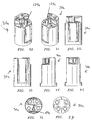
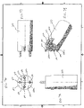
- reference numeral 10 generally identifies a water purifier having a cylindrical housing 12 extending along a longitudinal axis.
- a hollow, axially-extending sleeve 14 is centrally mounted within the housing 12 between apertured support walls 18, 20 spaced apart along the longitudinal axis.
- a water inlet 22 admits pressurized water to be purified into the space 16.
- a water outlet 24 discharges the purified water from the space 16.
- the space 16 serves as a flow-through passage for the water contained therein which, during the course of its flow, is exposed to ultraviolet radiation as described below.
- a removable cover 26 overlies the support wall 18 at one end of the housing 12.
- the cover 26 is detachably coupled to the housing 12 by a set of threaded fasteners 28 to permit access to the interior of the sleeve 14 through the aperture of the support wall 18.
- An electrical socket 30 is removably mounted within the aperture of the support wall 18.
- An ultraviolet lamp 32 is slidably inserted into the interior of the sleeve 14 through the aperture of the support wall 18.
- An electrical connection, as described below, is made with the socket 30. In operation, the lamp 32 emits ultraviolet radiation of sufficient intensity to kill microorganisms in the water, other liquid or air contained in the space 16 to purify the same for domestic and commercial applications.
- the lamp 32 includes an elongated, hollow, sealed, arc tube 34 constituted of a light-transmissive material, e.g. silica quartz or other ultraviolet transmitting glass tube.
- the tube 34 has opposite end regions 36,38 spaced apart along the longitudinal axis.
- a gas preferably mercury vapor with or without additives, is sealingly contained within the tube.
- a pair of electrodes 40, 42 is respectively mounted within the tube at the end regions 36, 38.
- a pair of end caps 44, 46 constituted of a non-conducting material, e.g. ceramic, is respectively mounted at the end regions 36, 38 over the sealed end regions of the tube.
- Each end cap has a bore having a closed base against which a sealed end region of the tube abuts when the sealed end region is inserted fully into a respective end cap.
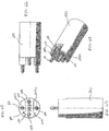
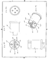
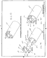
- End cap 44 (best show in FIGURES 10 and 10A ) also has a barrier wall 70a, 70b, extending between semi-circular bases 72, 74 such that bases 72, 74 are stepped with base 72 being the upper or distal base and base 74 being the lower or proximal base.
- a male member 75 extends laterally from barrier wall 70a, 70b, along lower base 74. Member 75 is centrally positioned along wall 70a, 70b thus splitting the wall into the two sections 70a and 70b. Member 75 has a height which is equal to the distance between respective bases 72 and 74. Member 75 also acts to divide lower base 74 into two symmetrical sections (each comprising an approximately 90 degree quadrant).
- a first pair of electrical contacts or terminal pins 48, 50 extends in mutual parallelism along the longitudinal axis, and is mounted on, and extends outwardly of, the end cap 44 (through base 72).
- a second pair of electrical contacts or terminal pins 52, 54 also extends in mutual parallelism along the longitudinal axis, and is also mounted on, and extends outwardly of, the same end cap 44 (through base 74). Pins 52 and 54 are separated from one another by member 75.
- the pins 48, 50 extend into interior compartment 76, and the pins 52, 54 extend into compartment 78 (see FIGURE 10A ).
- the pins 48, 50 are electrically connected within end cap 44 to one end of a wire conductor 56.
- the conductor 56 is located exteriorly of the tube 34, and extends along the longitudinal axis to the opposite end cap 46 wherein the other end of the conductor 56 is connected to the electrode 42.
- the pins 52, 54 are electrically connected within the end cap 44 to the electrode 40.
- the barrier wall 70a, 70b physically separates the pairs of pins.
- the end cap 44 has a stepped, outer end wall having a pair of semi-circular end wall portions 72, 74 lying in mutual parallelism in planes generally perpendicular to the longitudinal axis.
- the socket 30 has a complementary stepped, outer end wall together with a centrally located recess 76. During mating, the pins 48, 50, 52, 54 will be received into respective sockets 78, 80, 82, 84 while member 75 is received into mating recess 76.
- a set of centering rings 62, 64 preferably constituted of a synthetic plastic material, is located on tube 34, being placed thereon before the end caps are attached to the end regions of the tube 34.
- the rings 62, 64 coaxially surround the tube 34 and frictionally engage and support the tube, and assist in centering the tube within sleeve 14.
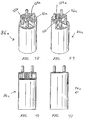
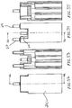
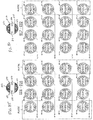
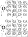
- FIGURES 11-14 additional embodiments of the end cap depicted in FIGURE 10 are shown. All of these end caps have a similar configuration to that shown in FIGURE 10 including a pair of parallel but longitudinally displaced semi-circular bases 72, 74 having a barrier wall 70a, 70b, extending therebetween so as to form a stepped base.
- a male member or extension extends centrally outwardly from barrier wall 70a, 70b. While this male extension was in the form of a relatively thin wall 75 in the end cap 44 of FIGURE 10 , the male extension takes on a differing geometric shape in the various embodiments shown in FIGURES 11-14 .
- the end cap 86 in FIGURE 11 has a rounded arcuate shape (e.g., V-shaped, semi-circular shaped) extension 102 extending between barrier wall sections 70a and 70b.
- the end cap 88 in FIGURE 12 has an extension 104 in the shape of a rectangular box which includes a pair of opposed sidewalls 106, 108 which extend outwardly from and perpendicularly to respective barrier wall sections 70a and 70b.
- the end cap 90 of FIGURE 13 also has a box like extension 110 which is similar to extension 104 (in FIGURE 12 ); however, extension 112 has a more square cross-section relative to the rectangular cross-section of extension 104.
- barrier wall sections 70a and 70b in FIGURE 13 are relatively larger than the respective barrier wall sections 70a and 70b in FIGURE 12 .
- End cap 92 in FIGURE 14 is a V-shaped triangular shape extension member 112 which forms the divider between barrier wall sections 70a and 70b.
- FIGURES 11-14 have in common the feature of FIGURE 10 wherein a male member extends outwardly from barrier wall 70a, 70b, and is coextensive with stepped (that is longitudinally displaced) base sections 72, 74.
- the male member may have any suitable configuration besides those shown in FIGURES 10-14 and that such configuration may be symmetrical, asymmetrical, spherical, conical, aspheric or any other desired shapes.
- receptacle 94 of FIGURE 16 has a rounded arcuate shaped recess 114 for receiving and mating with rounded or U-shaped extension 102 in FIGURE 11 .
- receptacle 96 has a rectangular shaped recess 116 which is sized and configured to mate with and be received by rectangular extension 104 in FIGURE 12 .
- Receptacle 98 in FIGURE 18 has a square shaped recess 118 for mating with and being received by square shaped extension 110 in FIGURE 13 while receptacle 100 of FIGURE 19 has a V-shaped recess 120 for mating with and being received by V-shaped extension 112 in FIGURE 14 .
- the receptacles of FIGURES 15-19 may include a recess having any desired shape, so long as the shape is complimentary to, and can be received by, the shape of the extensions in the mating end cap.
- the male extension in the plug ended lamp and the female recess in the complimentary receptacle may be reversed such that the lamp cap will exhibit the recess while the receptacle will exhibit the complimentary male extension for mating with the recess in the cap.
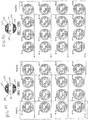
- Such alternative configurations are shown in the end caps of FIGURES 20-24 and also in FIGURES. 38-45 .
- the end caps of FIGURES 20-24 and 38-45 are similar to the respective end caps shown in FIGURES 10-14 with the only difference being that the male extension has been substituted with the female recess in FIGURES 20-24 .
- end cap 44' includes a narrow recess 122 (similar to the recess 76 shown in FIGURE 15 ), end cap 86' and 86a include an arcuate shaped recess 124, 124a (similar to the recess 114 in FIGURE 16 ), end cap 88' includes a rectangularly shaped recess 126 (similar to the recess 116 in FIGURE 17 ), end cap 90' of FIGURE 23 includes a square shaped recess 128 (similar to the recess 118 in FIGURE 18 ) and end cap 92' of FIGURE 24 includes a V-shaped recess 130 (similar to the V-shaped recess 120 of FIGURE 19 ).
- receptacles or bases are shown which are configured to mate with the end caps of FIGURES 20-24 and 38-45, respectively.
- receptacle 30' of FIGURE 25 includes male extension 132 which is sized and configured to be received by recess 122 in FIGURE 20 .
- Receptacle 30a of FIGURES 30-37 includes male extension 134a which is sized and configured to be received by recess 124a in FIGURE 38.
- Fig. 38 also shows how semi-circular bases 72a may contain an asymmetrical section 72b which may be added to help ensure that unauthorized parts are unable to be used.
- FIGURES 30-37 may be used with the corresponding end caps or bases shown in FIGURES 38-45 or the designs may be exchanged with each other, i.e., the end cap may look like the receptacle or base or vice versa.
- Receptacle 94' of FIGURE 26 includes arcuate shaped male extension 134 which is sized and configured to be received by arcuate recess 124 in FIGURE 21 .
- receptacle 96' of FIGURE 27 includes a rectangular extension 136 which is sized and configured to be received by rectangular recess 126 of FIGURE 22
- receptacle 98' of FIGURE 28 includes a square shaped extension 138 which is sized and configured to be received by squared shaped recess 128 in FIGURE 23
- receptacle 100' of FIGURE 29 includes a triangular shaped extension 140 which is sized and configured to be received by rectangular shaped recess 130 in FIGURE 24 .
- the cover 26 is removed, and a lamp 32 is inserted into the interior of the sleeve 14 via the aperture in the support wall 18.
- the socket 30 is connected to the pins 48, 50, 52, 54.
- the cover 26 is installed on the housing 12.
- Electrical wires 66,68 extend exteriorly of the socket to a non-illustrated electrical power supply. A voltage difference across the wires 66,68 is applied to both electrodes 40, 42 causing an electrical discharge within the tube. This discharge causes ultraviolet radiation to be emitted. This radiation passes through the light-transmissive wall of the sleeve 14 to irradiate the water contained in the space 16.
- the aforementioned barrier wall 70a, 70b prevents arcing interiorly of the end cap 44 by physically separating the electrical connections between the pins 48, 50 and the wire conductor, on the one hand, and the electrical connections between the pins 52, 54 and the electrode 40, on the other hand. The pairs of pins are thus effectively isolated.
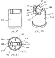
- a lamp base 200 includes at least a first step portion and a second step portion, as seen in Figures 46-48 .
- Figures 46-48 illustrate various views of a lamp base 200 according to at least an embodiment of the present invention.
- the lamp base 200 is generally cylindrical in shape and has an end surface 202. Additionally, a first step portion and a second step portion may extend outward from end surface 202 of lamp base 200.
- the first step portion includes a curved face 220a, a flat face 220b, and a raised face 220c.
- the second step portion includes a curved face 222a, a flat face 222b and a raised face 222c.
- Curved faces 220a, 222a and flat faces 220b, 222b extend perpendicular to the end surface.
- Raised faces 220c, 222c are perpendicular to curved faces 220a, 222a and flat faces 220b, 222b, respectively.
- Lamp base 200 also includes a number of pin connectors.
- a first upper pin connector 212 extends from the raised face 220c of the first step portion
- a second upper pin connector 214 extends from the raised face 222c of the second step portion
- a first lower pin connector 216 and a second lower pin connector 218 extend from the end surface.
- the first and second lower pin connectors 216, 218 are arranged in a variety of configurations.
- the first and second lower pin connectors 216, 218 are arranged symmetrically with respect to a center of the end surface, as seen in Figures 85-88 .
- the first and second lower pin connectors 216, 218 are arranged asymmetrically with respect to a center of the end surface, as seen in Figures 89-92 .
- key recesses 240 are provided an the lamp base 200 to help in alignment when coupling with a socket, as explained in more detail below. As seen in Figure 48 , for example, key recesses 240 are provided in the flat faces 220b, 222b of the first and second step portions.
- Figure 85 shows how a key recess can be found at one of at least four positions (key #1, key #2, key #3, key #4) in the flat face of the step portion. Additionally, Figure 85 shows how a key recess can be found at one of at least four positions (key #5, key #6, key #7, key #8). It is important to note that the keys can be placed independent from each other, and thus many possible combinations of key positions can be achieved. It will also be appreciated that the key positions are not limited to only the positions shown in Figure 85 , and that other suitable positions are also possible.
- the first step portion also includes a first truncated portion 232 and a second truncated portion 234.
- truncated portions 232, 234 are flat surfaces where it appears that the step portion has been truncated, or "cut off.”
- the truncated portions 232, 234 are provided at a first and second end of the first step portion.
- the first truncated portion 232 may be provided at a first end of a first step portion
- a second truncated portion 234 may be provided at a first end of a second truncated portion.
- the truncated portions help to ensure proper alignment when a lamp base is coupled with a socket, as explained in more detail below.
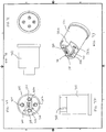
- FIGS 49-51 illustrate at least one possible embodiment of a socket 300.
- the socket 300 is generally cylindrical in shape and has an end surface. Additionally, a central step portion 310 extends perpendicular to the end surface of socket 300. Central step portion 310 may include a first flat face 314 extending perpendicular to the end surface and a second flat face 316 extending perpendicular to the end surface.
- socket 300 includes a first upper connector 326 provided within a recess formed in the central step portion 310 and a second upper connector 328 provided within a recess formed in the central step portion 310.
- Socket 300 also includes a first lower connector 322 provided within a recess formed in the end surface, and a second lower connector 324 provided within a recess formed in the end surface.
- the first and second upper connectors 326, 328 may be positioned either symmetrically or asymmetrically with respect to a center of the end surface of the socket 300.
- Figures 50-51 also illustrate that the socket 300 includes key protrusions 340 protruding out from the first flat face 314 and the second flat face 316. These key protrusions 340 can be positioned in a wide variety of configurations, complementing the wide variety of configurations possible for key recesses 240.
- socket 300 also includes a first tapered portion 312a and a second tapered portion 312b.
- the tapered portions 312a, 312b extend out from the first and second ends of first flat face 314, as seen in Figure 51 , for example, or a first tapered portion 312a extends out from a first end of first flat face 314 while the second tapered portion 312b extends out from a first end of second flat face 316.
- Figures 52-73 and 76-93 show various additional views of at least some possible embodiments and configurations of lamp bases 200 and sockets 300.
- Figures 74 and 75 show how a lamp base 200 and a socket 300 according to at least an embodiment of the present invention can couple with each other.
- Lamp base 200 and socket 300 are structured such that first upper pin connector 212 couples with first lower connector 322, second upper pin connector 214 couples with second lower pin connector 324, first lower pin connector 216 couples with first upper connector 326, and second lower pin connector 218 couples with second upper connector 328.
- the key recesses 240 of lamp base 200 are structured to align with the key protrusions 340 of the socket 300 when the lamp base and the socket are coupled.
- key protrusions 340 will slide into key recesses 240. If lamp base 200 is misaligned with socket 300, then the key protrusions 340 will not align with the key recess 240.
- first tapered portion 312a will align with first truncated portion 232
- second tapered portion 312b will align with the second truncated portion 234.
- the alignment features described above can ensure that there is only one possible way for a lamp base to fit into the socket.
- the alignment features ensure that the first upper pin connector 212 will always couple with the first lower connector 322, the second upper pin connector 214 will always couple with the second lower connector 324, etc. This is an important safety feature because it prevents the pin connectors from mistakenly being connected to the wrong polarity of a power source, for example, which could damage the lamp.
- the alignment features described above can help to prevent damage to lamps by ensuring proper coupling.
- an appropriate socket may have a given configuration of key protrusions 340 and/or tapered portions 312a, 312b, and unless the lamp base is a properly corresponding lamp base that has complementary key recesses 240 and/or truncated portions 232, 234, the lamp base cannot be coupled to the socket.
- an adaptor may be provided so that lamp bases may be retrofitted to couple with new sockets.
- lamp base 400 is a simple lamp base with four pin connectors 450, 452.
- Adaptor 410 can be fitted onto the end of lamp base 400.
- Adaptor 410 has a flat face 415, and end face 410 that is perpendicular to the flat face 415, and a key recess 440.
- adaptor 410 simulates a step portion and pin connector 450 extends through adaptor 410.
- a second adaptor 410 can be also be fitted so that the lamp base 400 has two step portions.
- the key recesses 440 an the adaptors can be configured to match the key protrusions of a corresponding socket. In this way, it is possible to achieve the benefits of ensuring proper alignment when coupling a lamp base and socket, as described above, by simply upgrading already existing lamp bases with adaptors 410.
Landscapes
- Health & Medical Sciences (AREA)
- Life Sciences & Earth Sciences (AREA)
- Engineering & Computer Science (AREA)
- Chemical & Material Sciences (AREA)
- Epidemiology (AREA)
- Hydrology & Water Resources (AREA)
- Environmental & Geological Engineering (AREA)
- Water Supply & Treatment (AREA)
- Microelectronics & Electronic Packaging (AREA)
- Organic Chemistry (AREA)
- Toxicology (AREA)
- Animal Behavior & Ethology (AREA)
- General Health & Medical Sciences (AREA)
- Public Health (AREA)
- Veterinary Medicine (AREA)
- Physical Water Treatments (AREA)
- Arrangement Of Elements, Cooling, Sealing, Or The Like Of Lighting Devices (AREA)
- Fastening Of Light Sources Or Lamp Holders (AREA)
Claims (16)
- Lampensockel (200), der an ein Ende eines Lampenkolbens montierbar ist und ausgebildet ist, mit einer Fassung (300) verbindbar zu sein, wobei der Lampensockel (200) aufweist:einen zylinderförmigen Körper, der eine Endfläche (202) aufweist;einen ersten Stufenabschnitt und einen zweiten Stufenabschnitt, die jeweils eine flache Fläche (220b, 222b) aufweisen, die sich rechtwinklig zu der Endfläche (202) erstreckt, und eine erhöhte Fläche (220c, 222c), die rechtwinklig zu der flachen Fläche (220b, 222b) ist;ein erster oberer Stiftverbinder (212), der an der erhöhten Fläche (220c) des ersten Stufenabschnitts vorgesehen ist und sich rechtwinklig zu dem ersten Stufenabschnitt erstreckt;ein zweiter oberer Stiftverbinder (214), der an der erhöhten Fläche (222c) des zweiten Stufenabschnitts vorgesehen ist und sich rechtwinklig zu dem ersten Stufenabschnitt erstreckt;ein erster (216) und ein zweiter (218) unterer Stiftverbinder, die an der Endfläche (202) vorgesehen sind und sich rechtwinklig zu der Endfläche (202) erstrecken;wobei der Lampensockel (200) ausgelegt ist, mit einer Fassung (300) durch lineares Einfügen der Stiftverbinder (212, 214, 216, 218) in korrespondierende Anschlussbuchsen an der Fassung verbindbar zu sein, dadurch gekennzeichnet, dassder Lampensockel (300) ferner eine erste Schlüsselvertiefung (240) aufweist, die in der flachen Fläche (220b) des ersten Stufenabschnitts vorgesehen ist, wobei die erste Schlüsselvertiefung (240) derart aufgebaut ist, dass, wenn der Lampensockel (200) mit der Fassung (300) verbunden wird, die erste Schlüsselvertiefung (240) mit einem ersten Schlüsselvorsprung (340) der Fassung (300) fluchtet.
- Lampensockel (200) nach Anspruch 1, ferner aufweisend eine zweite Schlüsselvertiefung (240), die in der flachen Fläche (222b) des zweiten Stufenabschnitts vorgesehen ist.
- Lampensockel (200) nach Anspruch 1, wobei der erste (216) und der zweite (218) untere Stiftverbinder bezüglich einer Mitte der Endfläche (202) symmetrisch platziert sind.
- Lampensockel (200) nach Anspruch 1, wobei der erste (216) und der zweite (218) untere Stiftverbinder bezüglich einer Mitte der Endfläche (202) asymmetrisch platziert sind.
- Lampensockel (200) nach Anspruch 1, wobei der erste Stufenabschnitt ferner aufweist:einen ersten angeschnittenen Abschnitt (232), der an einem ersten Ende des ersten Stufenabschnitts vorgesehen ist; undeinen zweiten angeschnittenen Abschnitt (234), der an einem zweiten Ende des ersten Stufenabschnitts vorgesehen ist.
- Lampensockel (200) nach Anspruch 1, wobei der erste Stufenabschnitt einen ersten angeschnittenen Abschnitt (232) aufweist, der an einem ersten Ende des ersten Stufenabschnitts vorgesehen ist; und der zweite Stufenabschnitt einen ersten zweiten angeschnittenen Abschnitt (234) aufweist, der an einem ersten Ende des ersten zweiten Stufenabschnitts vorgesehen ist.
- Fassung (300), die ausgebildet ist, mit einem Lampensockel (200) verbindbar zu sein, aufweisend:einen zylinderförmigen Körper, der eine Endfläche aufweist;einen mittigen Stufenabschnitt (310), der sich rechtwinklig zu der Endfläche erstreckt, wobei der mittige Stufenabschnitt (310) aufweist:eine erste flache Fläche (314), die sich rechtwinklig zu der Endfläche erstreckt; undeine zweite flache Fläche (316), die sich rechtwinklig zu der Endfläche erstreckt;eine erste obere Anschlussbuchse (326), die in einer Vertiefung vorgesehen ist, die in dem mittigen Stufenabschnitt (310) gebildet ist;eine zweite obere Anschlussbuchse (328), die in einer Vertiefung vorgesehen ist, die in dem mittigen Stufenabschnitt (310) gebildet ist;eine erste untere Anschlussbuchse (322), die in einer Vertiefung vorgesehen ist, die in der Endfläche gebildet ist;eine zweite untere Anschlussbuchse (324), die in einer Vertiefung vorgesehen ist, die in der Endfläche gebildet ist; undwobei die Fassung (300) ausgelegt ist, mit dem Lampensockel (200) durch lineares Aufnehmen von Stiftverbindern (212, 214, 216, 218) des Lampensockels (200) in die korrespondierenden Anschlussbuchsen (322, 324, 326, 328) verbindbar zu sein,dadurch gekennzeichnet, dass die Fassung (300) einen ersten Schlüsselvorsprung (340) aufweist, der von der ersten flachen Fläche (314) vorsteht, wobei der erste Schlüsselvorsprung (340) derart aufgebaut ist, dass, wenn die Fassung (300) mit dem Lampensockel (200) verbunden wird, der erste Schlüsselvorsprung (340) mit einer ersten Schlüsselvertiefung (240) des Lampensockels (200) fluchtet.
- Fassung (300) nach Anspruch 7, ferner aufweisend einen zweiten Schlüsselvorsprung (340), der von der zweiten flachen Fläche (316) vorsteht.
- Fassung (300) nach Anspruch 7, wobei die erste obere Anschlussbuchse (326) und die zweiten obere Anschlussbuchse (328) bezüglich einer Mitte der Endfläche symmetrisch platziert sind.
- Fassung (300) nach Anspruch 7, wobei die erste obere Anschlussbuchse (326) und die zweite obere Anschlussbuchse (328) bezüglich einer Mitte der Endfläche asymmetrisch platziert sind.
- Fassung (300) nach Anspruch 7, ferner aufweisend:einen ersten angeschrägten Abschnitt (312a), der sich von einem ersten Ende der ersten flachen Fläche (314) nach außen erstreckt; undeinen zweiten angeschrägten Abschnitt (312b), der sich von einem zweiten Ende der ersten flachen Fläche (314) nach außen erstreckt.
- Fassung (300) nach Anspruch 7, ferner aufweisend:einen ersten angeschrägten Abschnitt (312a), der sich von einem ersten Ende der ersten flachen Fläche (314) nach außen erstreckt; undeinen zweiten angeschrägten Abschnitt (312b), der sich von einem ersten Ende der zweiten flachen Fläche (316) nach außen erstreckt
- Anordnung aus einem Lampensockel (200) und einer Fassung (300) zur Verwendung mit einem Lampenkolben, wobei die Anordnung aufweist:einen Lampensockel (200), der aufgebaut ist, auf ein Ende eines Lampenkolbens zu passen, wobei der Lampensockel (200) aufweist:einen zylinderförmigen Lampensockelkörper, der eine Sockelendfläche (202) aufweist;einen ersten Stufenabschnitt und einen zweiten Stufenabschnitt, die jeweils eine flache Fläche (220b, 222b) aufweisen, die sich rechtwinklig zu der Sockelendfläche (202) erstreckt, und eine erhöhte Fläche (220c, 222c), die rechtwinklig zu der flachen Fläche (220b, 222b) ist;ein erster oberer Stiftverbinder (212), der an der erhöhten Fläche (220c) des ersten Stufenabschnitts vorgesehen ist und sich rechtwinklig zu dem ersten Stufenabschnitt erstreckt;ein zweiter oberer Stiftverbinder (214), der an der erhöhten Fläche (222c) des zweiten Stufenabschnitts vorgesehen ist und sich rechtwinklig zu dem ersten Stufenabschnitt erstreckt; undein erster (216) und ein zweiter (218) unterer Stiftverbinder, die an der Sockelendfläche (202) vorgesehen sind und sich rechtwinklig zu der Endfläche (202) erstrecken; undeine Fassung (300), die aufgebaut ist, mit dem Lampensockel verbindbar zu sein, wobei die Fassung (300) aufweist:einen zylinderförmigen Fassungskörper, der eine Fassungsendfläche aufweist;einen mittigen Stufenabschnitt (310), der sich rechtwinklig zu der Fassungsendfläche erstreckt, wobei der mittige Stufenabschnitt (310) eine erste flache Fläche (314) aufweist, die sich rechtwinklig zu der Endfläche erstreckt; und eine zweite flache Fläche (316), die sich rechtwinklig zu der Endfläche erstreckt;eine erste obere Anschlussbuchse (326), die in einer Vertiefung vorgesehen ist, die in dem mittigen Stufenabschnitt (310) gebildet ist;eine zweite obere Anschlussbuchse (328), die in einer Vertiefung vorgesehen ist, die in dem mittigen Stufenabschnitt (310) gebildet ist;eine erste untere Anschlussbuchse (322), die in einer Vertiefung vorgesehen ist, die in der Endfläche gebildet ist; undeine zweite untere Anschlussbuchse (324), die in einer Vertiefung vorgesehen ist, die in der Endfläche gebildet ist;wobei die erste untere Anschlussbuchse (322) und die zweite untere Anschlussbuchse (324) aufgebaut sind, mit dem ersten oberen Stiftverbinder (212) und dem zweiten oberen Stiftverbinder (214) durch lineares Einfügen des ersten oberen Stiftverbinders (212) und des zweiten oberen Stiftverbinders (214) in die erste untere Anschlussbuchse (322) beziehungsweise die zweite untere Anschlussbuchse (324) verbindbar zu sein;wobei die erste obere Anschlussbuchse (326) und die zweite obere Anschlussbuchse (328) aufgebaut sind, mit dem ersten unteren Stiftverbinder (216) und dem zweiten unteren Stiftverbinder (218) durch lineares Einfügen des ersten unteren Stiftverbinders (216) und des zweiten unteren Stiftverbinders (218) in die erste obere Anschlussbuchse (326) beziehungsweise die zweite obere Anschlussbuchse (328) verbindbar zu sein;wobei der mittige Stufenabschnitt (310) aufgebaut ist, zwischen den ersten Stufenabschnitt und den zweiten Stufenabschnitt zu passen, wenn die Fassung (300) und der Lampensockel (200) verbunden sind; undwobei die Anordnung ferner gekennzeichnet ist durcheine erste Schlüsselvertiefung (240), die in der flachen Fläche (220b) des ersten Stufenabschnitts vorgesehen ist, undeinen ersten Schlüsselvorsprung (340), der von der ersten flachen Fläche (314) vorsteht;und dadurch, dass der erste Schlüsselvorsprung (340) aufgebaut ist, mit der ersten Schlüsselvertiefung (240) zu fluchten, wenn die Fassung (300) und der Lampensockel (200) miteinander verbunden sind.
- Anordnung nach Anspruch 13, ferner aufweisend:eine zweite Schlüsselvertiefung (240), die in der flachen Fläche (222b) des zweiten Stufenabschnitts vorgesehen ist;und ein zweiter Schlüsselvorsprung (340), der von der zweiten flachen Fläche (316) vorsteht;wobei der zweite Schlüsselvorsprung (340) aufgebaut ist, mit der zweiten Schlüsselvertiefung (240) zu fluchten, wenn die Fassung (300) und der Lampensockel (200) miteinander verbunden sind.
- Anordnung nach Anspruch 13, wobei
der erste Stufenabschnitt ferner einen ersten angeschnittenen Abschnitt (232) aufweist, der an einem ersten Ende des ersten Stufenabschnitts vorgesehen ist, und einen zweiten angeschnittenen Abschnitt (234), der an einem zweiten Ende des ersten Stufenabschnitts vorgesehen ist;
sich ein erster angeschrägter Abschnitt (312a) von einem ersten Ende der ersten flachen Fläche (314) nach außen erstreckt;
sich ein zweiter angeschrägter Abschnitt (312b) von einem zweiten Ende der ersten flachen Fläche (314) nach außen erstreckt; und
der erste angeschrägte Abschnitt (312a) mit dem ersten angeschnittenen Abschnitt (232) fluchtet und der zweite angeschrägte Abschnitt (312b) mit dem zweiten angeschnittenen Abschnitt (234) fluchtet, wenn die Fassung (300) mit dem Lampensockel (200) verbunden ist. - Anordnung nach Anspruch 13, wobei
der erste Stufenabschnitt ferner einen ersten angeschnittenen Abschnitt (232) aufweist, der an einem ersten Ende des ersten Stufenabschnitts vorgesehen ist; der zweite Stufenabschnitt ferner einen zweiten angeschnittenen Abschnitt (234) aufweist, der an einem ersten Ende des zweiten ersten Stufenabschnitts vorgesehen ist;
sich ein erster angeschrägter Abschnitt (312a) von einem ersten Ende der ersten flachen Fläche nach außen erstreckt;
sich ein zweiter angeschrägter Abschnitt (312b) von einem ersten Ende der zweiten flachen Fläche nach außen erstreckt; und
der erste angeschrägte Abschnitt (312a) mit dem ersten angeschnittenen Abschnitt (232) fluchtet und der zweite angeschrägte Abschnitt (312b) mit dem zweiten angeschnittenen Abschnitt (234) fluchtet, wenn die Fassung (300) mit dem Lampensockel (200) verbunden ist.
Applications Claiming Priority (3)
| Application Number | Priority Date | Filing Date | Title |
|---|---|---|---|
| US11/675,315 US7390222B2 (en) | 2006-02-27 | 2007-02-15 | Ultraviolet lamp for use in water purifiers |
| US11/870,256 US7795813B2 (en) | 2006-02-27 | 2007-10-10 | Ultraviolet lamp for use in water purifiers |
| PCT/US2008/054118 WO2008101181A2 (en) | 2007-02-15 | 2008-02-15 | Ultraviolet lamp for use in water purifiers |
Publications (3)
| Publication Number | Publication Date |
|---|---|
| EP2118967A2 EP2118967A2 (de) | 2009-11-18 |
| EP2118967A4 EP2118967A4 (de) | 2011-05-25 |
| EP2118967B1 true EP2118967B1 (de) | 2016-05-04 |
Family
ID=39690820
Family Applications (2)
| Application Number | Title | Priority Date | Filing Date |
|---|---|---|---|
| EP08730003.4A Active EP2118967B1 (de) | 2007-02-15 | 2008-02-15 | Uv-lampe zur verwendung für wasserreinigungsfilter |
| EP08730006.7A Active EP2126952B1 (de) | 2007-02-15 | 2008-02-15 | Uv-lampe zur verwendung für wasserreinigungsfilter |
Family Applications After (1)
| Application Number | Title | Priority Date | Filing Date |
|---|---|---|---|
| EP08730006.7A Active EP2126952B1 (de) | 2007-02-15 | 2008-02-15 | Uv-lampe zur verwendung für wasserreinigungsfilter |
Country Status (9)
| Country | Link |
|---|---|
| US (1) | US7795813B2 (de) |
| EP (2) | EP2118967B1 (de) |
| CN (2) | CN101803117B (de) |
| CA (2) | CA2677272C (de) |
| DK (1) | DK2118967T3 (de) |
| HU (1) | HUE028970T2 (de) |
| MX (2) | MX2009008647A (de) |
| PL (2) | PL2126952T3 (de) |
| WO (2) | WO2008101182A2 (de) |
Families Citing this family (4)
| Publication number | Priority date | Publication date | Assignee | Title |
|---|---|---|---|---|
| US9062870B2 (en) | 2013-05-10 | 2015-06-23 | Caldesso, Llc | UV bulb configuration |
| JP6219103B2 (ja) * | 2013-09-18 | 2017-10-25 | 千代田工販株式会社 | 紫外線ランプと保護管の組付け構造 |
| CN108321584A (zh) * | 2017-01-16 | 2018-07-24 | 佛山市美的清湖净水设备有限公司 | 用于净饮机的uv灯组件的uv灯接头、uv灯组件和净饮机 |
| US11894642B2 (en) * | 2018-07-12 | 2024-02-06 | Illinois Tool Works Inc. | Reconfigurable welding-type power sockets and power plugs |
Family Cites Families (32)
| Publication number | Priority date | Publication date | Assignee | Title |
|---|---|---|---|---|
| US2135267A (en) * | 1936-02-25 | 1938-11-01 | Alden Milton | Electrical plug and socket |
| US2297188A (en) * | 1940-04-15 | 1942-09-29 | Joyce John | Electric plug and socket |
| GB694114A (en) | 1950-08-09 | 1953-07-15 | Gen Electric Co Ltd | Improvements in or relating to holders for electrical devices especially electric discharge lamps |
| US3059214A (en) * | 1960-01-18 | 1962-10-16 | Watts Electric & Mfg Co | Connector structure |
| US3761862A (en) * | 1971-05-17 | 1973-09-25 | J Spiteri | Dual voltage drop light |
| US4075531A (en) * | 1977-01-03 | 1978-02-21 | Zenith Radio Corporation | Base-socket system with arc prevention means |
| US4256989A (en) * | 1978-09-22 | 1981-03-17 | Duro Test Corporation | Incandescent lamp with filament mounting means and socket adaptor |
| US4528429A (en) * | 1984-03-02 | 1985-07-09 | Dart Industries Inc. | Electrical switch-plug assembly with baffle |
| USD300215S (en) * | 1985-09-24 | 1989-03-14 | Leviton Manufacturing Company, Inc. | Lockable mount for an electric lamp socket |
| US4740169A (en) * | 1987-02-17 | 1988-04-26 | Gordon Steven C | Electrical plug protector and cleaner |
| US5040993A (en) * | 1988-12-19 | 1991-08-20 | Colorado Memory Systems, Inc. | Interchangeable adapter module for electronic devices |
| US4990099A (en) * | 1989-09-18 | 1991-02-05 | High Voltage Engineering Corp. | Keyed electrical connector with main and auxiliary electrical contacts |
| US5120268A (en) * | 1990-08-07 | 1992-06-09 | Al Gerrans | Marine electrical connector |
| US5166527A (en) * | 1991-12-09 | 1992-11-24 | Puroflow Incorporated | Ultraviolet lamp for use in water purifiers |
| US5471063A (en) * | 1994-01-13 | 1995-11-28 | Trojan Technologies, Inc. | Fluid disinfection system |
| US5634820A (en) * | 1994-03-11 | 1997-06-03 | Lights Of America, Inc. | Fluorescent light adaptor module |
| US5422487A (en) * | 1994-07-27 | 1995-06-06 | Light Sources, Inc. | Waste water purification system with complementary interlocking germicidal lamp and socket construction |
| US5727963A (en) * | 1996-05-01 | 1998-03-17 | Lemaster; Dolan M. | Modular power connector assembly |
| US6638088B1 (en) * | 1997-04-23 | 2003-10-28 | Anthony, Inc. | Lighting circuit, lighting system method and apparatus, socket assembly, lamp insulator assembly and components thereof |
| DE19832352A1 (de) * | 1998-07-20 | 2000-01-27 | Walter Holzer | Berührungssicheres Sockel-/Fassungssystem für Leuchten |
| US6165013A (en) * | 1999-01-08 | 2000-12-26 | Broussard; Blaine L. | Method and apparatus waterproofing |
| US6685361B1 (en) * | 2000-06-15 | 2004-02-03 | Weatherford/Lamb, Inc. | Fiber optic cable connectors for downhole applications |
| US6634902B1 (en) * | 2002-05-17 | 2003-10-21 | Light Sources, Inc. | Purification lamp connector |
| US7137728B2 (en) * | 2003-01-15 | 2006-11-21 | Ultraviolet Devices, Inc. | Lamp keying system |
| US6884103B1 (en) * | 2004-02-04 | 2005-04-26 | Light Sources, Inc. | Secure lamp base and socket |
| US7569981B1 (en) | 2005-02-22 | 2009-08-04 | Light Sources, Inc. | Ultraviolet germicidal lamp base and socket |
| CA2613147C (en) | 2005-06-24 | 2013-11-26 | Trojan Technologies Inc. | Radiation lamp and radiation source module incorporating same |
| US7390225B2 (en) * | 2005-06-24 | 2008-06-24 | Trojan Technologies | Radiation lamp and radiation source module incorporating same |
| EP1989762A4 (de) * | 2006-02-27 | 2011-05-18 | Light Sources Inc | Ultraviolettlichtlampe zur verwendung in wasserreinigungsfiltern |
| ITTO20060228A1 (it) * | 2006-03-28 | 2007-09-29 | Tyco Electronics Amp Italia Spa | Connettore elettrico con elementi di chiusura |
| USD575742S1 (en) * | 2006-07-24 | 2008-08-26 | 3M Innovative Properties Company | Hermaphroditic electrical connector |
| CA2664021C (en) * | 2006-09-20 | 2013-06-11 | Trojan Technologies | Optical radiation sensor system |
-
2007
- 2007-10-10 US US11/870,256 patent/US7795813B2/en active Active
-
2008
- 2008-02-15 CN CN2008800071391A patent/CN101803117B/zh not_active Expired - Fee Related
- 2008-02-15 CA CA2677272A patent/CA2677272C/en active Active
- 2008-02-15 WO PCT/US2008/054121 patent/WO2008101182A2/en not_active Ceased
- 2008-02-15 WO PCT/US2008/054118 patent/WO2008101181A2/en not_active Ceased
- 2008-02-15 CN CN2008800080263A patent/CN101632147B/zh not_active Expired - Fee Related
- 2008-02-15 EP EP08730003.4A patent/EP2118967B1/de active Active
- 2008-02-15 CA CA2677275A patent/CA2677275C/en active Active
- 2008-02-15 DK DK08730003.4T patent/DK2118967T3/en active
- 2008-02-15 MX MX2009008647A patent/MX2009008647A/es active IP Right Grant
- 2008-02-15 PL PL08730006T patent/PL2126952T3/pl unknown
- 2008-02-15 HU HUE08730003A patent/HUE028970T2/en unknown
- 2008-02-15 MX MX2009008649A patent/MX2009008649A/es active IP Right Grant
- 2008-02-15 EP EP08730006.7A patent/EP2126952B1/de active Active
- 2008-02-15 PL PL08730003.4T patent/PL2118967T3/pl unknown
Also Published As
| Publication number | Publication date |
|---|---|
| PL2118967T3 (pl) | 2016-10-31 |
| MX2009008647A (es) | 2009-08-21 |
| US7795813B2 (en) | 2010-09-14 |
| EP2118967A4 (de) | 2011-05-25 |
| CN101632147B (zh) | 2012-06-13 |
| US20080246402A1 (en) | 2008-10-09 |
| CN101803117A (zh) | 2010-08-11 |
| CA2677272A1 (en) | 2008-08-21 |
| WO2008101181A3 (en) | 2009-01-15 |
| EP2118967A2 (de) | 2009-11-18 |
| PL2126952T3 (pl) | 2013-10-31 |
| CA2677275A1 (en) | 2008-08-21 |
| WO2008101181A2 (en) | 2008-08-21 |
| CN101803117B (zh) | 2013-02-13 |
| MX2009008649A (es) | 2009-08-21 |
| WO2008101182A3 (en) | 2009-01-08 |
| EP2126952A4 (de) | 2011-05-25 |
| EP2126952B1 (de) | 2013-06-05 |
| DK2118967T3 (en) | 2016-08-22 |
| CA2677275C (en) | 2017-01-10 |
| CN101632147A (zh) | 2010-01-20 |
| HUE028970T2 (en) | 2017-04-28 |
| CA2677272C (en) | 2016-03-29 |
| EP2126952A2 (de) | 2009-12-02 |
| WO2008101182A2 (en) | 2008-08-21 |
Similar Documents
| Publication | Publication Date | Title |
|---|---|---|
| US7604505B2 (en) | Ultraviolet lamp for use in water purifiers | |
| US8021189B2 (en) | Ultraviolet lamp for use in water purifiers | |
| US7661977B2 (en) | Snap-lock connector | |
| EP2070164B1 (de) | Schnappschlossverbinder | |
| AU2007217834B2 (en) | Ultraviolet lamp for use in water purifiers | |
| US8040032B2 (en) | Smooth action, spring loaded, twist locking, radial lugged safety connector for lamp | |
| EP2118967B1 (de) | Uv-lampe zur verwendung für wasserreinigungsfilter | |
| EP2392054B1 (de) | Schnappschlossvebinder | |
| ES2582659T3 (es) | Lámpara ultravioleta para usar en purificadores de agua |
Legal Events
| Date | Code | Title | Description |
|---|---|---|---|
| PUAI | Public reference made under article 153(3) epc to a published international application that has entered the european phase |
Free format text: ORIGINAL CODE: 0009012 |
|
| 17P | Request for examination filed |
Effective date: 20090915 |
|
| AK | Designated contracting states |
Kind code of ref document: A2 Designated state(s): AT BE BG CH CY CZ DE DK EE ES FI FR GB GR HR HU IE IS IT LI LT LU LV MC MT NL NO PL PT RO SE SI SK TR |
|
| DAX | Request for extension of the european patent (deleted) | ||
| A4 | Supplementary search report drawn up and despatched |
Effective date: 20110428 |
|
| 17Q | First examination report despatched |
Effective date: 20120508 |
|
| GRAP | Despatch of communication of intention to grant a patent |
Free format text: ORIGINAL CODE: EPIDOSNIGR1 |
|
| INTG | Intention to grant announced |
Effective date: 20151125 |
|
| GRAS | Grant fee paid |
Free format text: ORIGINAL CODE: EPIDOSNIGR3 |
|
| GRAA | (expected) grant |
Free format text: ORIGINAL CODE: 0009210 |
|
| AK | Designated contracting states |
Kind code of ref document: B1 Designated state(s): AT BE BG CH CY CZ DE DK EE ES FI FR GB GR HR HU IE IS IT LI LT LU LV MC MT NL NO PL PT RO SE SI SK TR |
|
| REG | Reference to a national code |
Ref country code: GB Ref legal event code: FG4D |
|
| REG | Reference to a national code |
Ref country code: CH Ref legal event code: EP |
|
| REG | Reference to a national code |
Ref country code: AT Ref legal event code: REF Ref document number: 797631 Country of ref document: AT Kind code of ref document: T Effective date: 20160515 |
|
| REG | Reference to a national code |
Ref country code: IE Ref legal event code: FG4D |
|
| REG | Reference to a national code |
Ref country code: RO Ref legal event code: EPE Ref country code: DE Ref legal event code: R096 Ref document number: 602008044000 Country of ref document: DE |
|
| REG | Reference to a national code |
Ref country code: NL Ref legal event code: FP |
|
| REG | Reference to a national code |
Ref country code: PT Ref legal event code: SC4A Ref document number: 2118967 Country of ref document: PT Date of ref document: 20160805 Kind code of ref document: T Free format text: AVAILABILITY OF NATIONAL TRANSLATION Effective date: 20160729 |
|
| REG | Reference to a national code |
Ref country code: SE Ref legal event code: TRGR |
|
| REG | Reference to a national code |
Ref country code: DK Ref legal event code: T3 Effective date: 20160816 |
|
| REG | Reference to a national code |
Ref country code: LT Ref legal event code: MG4D |
|
| REG | Reference to a national code |
Ref country code: ES Ref legal event code: FG2A Ref document number: 2582659 Country of ref document: ES Kind code of ref document: T3 Effective date: 20160914 |
|
| REG | Reference to a national code |
Ref country code: NO Ref legal event code: T2 Effective date: 20160504 |
|
| PG25 | Lapsed in a contracting state [announced via postgrant information from national office to epo] |
Ref country code: LT Free format text: LAPSE BECAUSE OF FAILURE TO SUBMIT A TRANSLATION OF THE DESCRIPTION OR TO PAY THE FEE WITHIN THE PRESCRIBED TIME-LIMIT Effective date: 20160504 |
|
| PG25 | Lapsed in a contracting state [announced via postgrant information from national office to epo] |
Ref country code: LV Free format text: LAPSE BECAUSE OF FAILURE TO SUBMIT A TRANSLATION OF THE DESCRIPTION OR TO PAY THE FEE WITHIN THE PRESCRIBED TIME-LIMIT Effective date: 20160504 Ref country code: HR Free format text: LAPSE BECAUSE OF FAILURE TO SUBMIT A TRANSLATION OF THE DESCRIPTION OR TO PAY THE FEE WITHIN THE PRESCRIBED TIME-LIMIT Effective date: 20160504 |
|
| REG | Reference to a national code |
Ref country code: FR Ref legal event code: PLFP Year of fee payment: 10 |
|
| PG25 | Lapsed in a contracting state [announced via postgrant information from national office to epo] |
Ref country code: SK Free format text: LAPSE BECAUSE OF FAILURE TO SUBMIT A TRANSLATION OF THE DESCRIPTION OR TO PAY THE FEE WITHIN THE PRESCRIBED TIME-LIMIT Effective date: 20160504 Ref country code: EE Free format text: LAPSE BECAUSE OF FAILURE TO SUBMIT A TRANSLATION OF THE DESCRIPTION OR TO PAY THE FEE WITHIN THE PRESCRIBED TIME-LIMIT Effective date: 20160504 |
|
| REG | Reference to a national code |
Ref country code: GR Ref legal event code: EP Ref document number: 20160401798 Country of ref document: GR Effective date: 20161118 |
|
| REG | Reference to a national code |
Ref country code: DE Ref legal event code: R097 Ref document number: 602008044000 Country of ref document: DE |
|
| PLBE | No opposition filed within time limit |
Free format text: ORIGINAL CODE: 0009261 |
|
| STAA | Information on the status of an ep patent application or granted ep patent |
Free format text: STATUS: NO OPPOSITION FILED WITHIN TIME LIMIT |
|
| 26N | No opposition filed |
Effective date: 20170207 |
|
| REG | Reference to a national code |
Ref country code: HU Ref legal event code: AG4A Ref document number: E028970 Country of ref document: HU |
|
| PG25 | Lapsed in a contracting state [announced via postgrant information from national office to epo] |
Ref country code: SI Free format text: LAPSE BECAUSE OF FAILURE TO SUBMIT A TRANSLATION OF THE DESCRIPTION OR TO PAY THE FEE WITHIN THE PRESCRIBED TIME-LIMIT Effective date: 20160504 |
|
| PG25 | Lapsed in a contracting state [announced via postgrant information from national office to epo] |
Ref country code: MC Free format text: LAPSE BECAUSE OF FAILURE TO SUBMIT A TRANSLATION OF THE DESCRIPTION OR TO PAY THE FEE WITHIN THE PRESCRIBED TIME-LIMIT Effective date: 20160504 |
|
| PG25 | Lapsed in a contracting state [announced via postgrant information from national office to epo] |
Ref country code: LU Free format text: LAPSE BECAUSE OF NON-PAYMENT OF DUE FEES Effective date: 20170215 |
|
| REG | Reference to a national code |
Ref country code: AT Ref legal event code: UEP Ref document number: 797631 Country of ref document: AT Kind code of ref document: T Effective date: 20160504 |
|
| REG | Reference to a national code |
Ref country code: FR Ref legal event code: PLFP Year of fee payment: 11 |
|
| PG25 | Lapsed in a contracting state [announced via postgrant information from national office to epo] |
Ref country code: MT Free format text: LAPSE BECAUSE OF NON-PAYMENT OF DUE FEES Effective date: 20170215 |
|
| PG25 | Lapsed in a contracting state [announced via postgrant information from national office to epo] |
Ref country code: BG Free format text: LAPSE BECAUSE OF FAILURE TO SUBMIT A TRANSLATION OF THE DESCRIPTION OR TO PAY THE FEE WITHIN THE PRESCRIBED TIME-LIMIT Effective date: 20160504 |
|
| PG25 | Lapsed in a contracting state [announced via postgrant information from national office to epo] |
Ref country code: CY Free format text: LAPSE BECAUSE OF NON-PAYMENT OF DUE FEES Effective date: 20160504 |
|
| PG25 | Lapsed in a contracting state [announced via postgrant information from national office to epo] |
Ref country code: IS Free format text: LAPSE BECAUSE OF FAILURE TO SUBMIT A TRANSLATION OF THE DESCRIPTION OR TO PAY THE FEE WITHIN THE PRESCRIBED TIME-LIMIT Effective date: 20160904 |
|
| PGFP | Annual fee paid to national office [announced via postgrant information from national office to epo] |
Ref country code: FR Payment date: 20210112 Year of fee payment: 14 Ref country code: GR Payment date: 20210112 Year of fee payment: 14 Ref country code: IT Payment date: 20210112 Year of fee payment: 14 Ref country code: IE Payment date: 20210209 Year of fee payment: 14 Ref country code: RO Payment date: 20210111 Year of fee payment: 14 Ref country code: NO Payment date: 20210208 Year of fee payment: 14 Ref country code: PT Payment date: 20210212 Year of fee payment: 14 Ref country code: NL Payment date: 20210212 Year of fee payment: 14 Ref country code: CH Payment date: 20210217 Year of fee payment: 14 Ref country code: CZ Payment date: 20210128 Year of fee payment: 14 Ref country code: FI Payment date: 20210209 Year of fee payment: 14 |
|
| PGFP | Annual fee paid to national office [announced via postgrant information from national office to epo] |
Ref country code: ES Payment date: 20210309 Year of fee payment: 14 Ref country code: GB Payment date: 20210203 Year of fee payment: 14 Ref country code: SE Payment date: 20210210 Year of fee payment: 14 Ref country code: TR Payment date: 20210212 Year of fee payment: 14 Ref country code: DK Payment date: 20210210 Year of fee payment: 14 Ref country code: BE Payment date: 20210114 Year of fee payment: 14 Ref country code: AT Payment date: 20210125 Year of fee payment: 14 |
|
| REG | Reference to a national code |
Ref country code: DK Ref legal event code: EBP Effective date: 20220228 |
|
| REG | Reference to a national code |
Ref country code: NO Ref legal event code: MMEP |
|
| REG | Reference to a national code |
Ref country code: FI Ref legal event code: MAE |
|
| REG | Reference to a national code |
Ref country code: SE Ref legal event code: EUG |
|
| REG | Reference to a national code |
Ref country code: NL Ref legal event code: MM Effective date: 20220301 |
|
| REG | Reference to a national code |
Ref country code: CH Ref legal event code: PL |
|
| REG | Reference to a national code |
Ref country code: AT Ref legal event code: MM01 Ref document number: 797631 Country of ref document: AT Kind code of ref document: T Effective date: 20220215 |
|
| REG | Reference to a national code |
Ref country code: BE Ref legal event code: MM Effective date: 20220228 |
|
| GBPC | Gb: european patent ceased through non-payment of renewal fee |
Effective date: 20220215 |
|
| PG25 | Lapsed in a contracting state [announced via postgrant information from national office to epo] |
Ref country code: SE Free format text: LAPSE BECAUSE OF NON-PAYMENT OF DUE FEES Effective date: 20220216 Ref country code: RO Free format text: LAPSE BECAUSE OF NON-PAYMENT OF DUE FEES Effective date: 20220215 Ref country code: PT Free format text: LAPSE BECAUSE OF NON-PAYMENT OF DUE FEES Effective date: 20220816 Ref country code: NO Free format text: LAPSE BECAUSE OF NON-PAYMENT OF DUE FEES Effective date: 20220228 Ref country code: GR Free format text: LAPSE BECAUSE OF NON-PAYMENT OF DUE FEES Effective date: 20220905 Ref country code: FI Free format text: LAPSE BECAUSE OF NON-PAYMENT OF DUE FEES Effective date: 20220215 Ref country code: CZ Free format text: LAPSE BECAUSE OF NON-PAYMENT OF DUE FEES Effective date: 20220215 Ref country code: AT Free format text: LAPSE BECAUSE OF NON-PAYMENT OF DUE FEES Effective date: 20220215 |
|
| PG25 | Lapsed in a contracting state [announced via postgrant information from national office to epo] |
Ref country code: NL Free format text: LAPSE BECAUSE OF NON-PAYMENT OF DUE FEES Effective date: 20220301 Ref country code: FR Free format text: LAPSE BECAUSE OF NON-PAYMENT OF DUE FEES Effective date: 20220228 |
|
| PG25 | Lapsed in a contracting state [announced via postgrant information from national office to epo] |
Ref country code: LI Free format text: LAPSE BECAUSE OF NON-PAYMENT OF DUE FEES Effective date: 20220228 Ref country code: IE Free format text: LAPSE BECAUSE OF NON-PAYMENT OF DUE FEES Effective date: 20220215 Ref country code: GB Free format text: LAPSE BECAUSE OF NON-PAYMENT OF DUE FEES Effective date: 20220215 Ref country code: DK Free format text: LAPSE BECAUSE OF NON-PAYMENT OF DUE FEES Effective date: 20220228 Ref country code: CH Free format text: LAPSE BECAUSE OF NON-PAYMENT OF DUE FEES Effective date: 20220228 |
|
| PG25 | Lapsed in a contracting state [announced via postgrant information from national office to epo] |
Ref country code: BE Free format text: LAPSE BECAUSE OF NON-PAYMENT OF DUE FEES Effective date: 20220228 |
|
| REG | Reference to a national code |
Ref country code: ES Ref legal event code: FD2A Effective date: 20230330 |
|
| PG25 | Lapsed in a contracting state [announced via postgrant information from national office to epo] |
Ref country code: ES Free format text: LAPSE BECAUSE OF NON-PAYMENT OF DUE FEES Effective date: 20220216 |
|
| PG25 | Lapsed in a contracting state [announced via postgrant information from national office to epo] |
Ref country code: IT Free format text: LAPSE BECAUSE OF NON-PAYMENT OF DUE FEES Effective date: 20220215 |
|
| PG25 | Lapsed in a contracting state [announced via postgrant information from national office to epo] |
Ref country code: TR Free format text: LAPSE BECAUSE OF NON-PAYMENT OF DUE FEES Effective date: 20220215 |
|
| PGFP | Annual fee paid to national office [announced via postgrant information from national office to epo] |
Ref country code: HU Payment date: 20250429 Year of fee payment: 18 |
|
| PGFP | Annual fee paid to national office [announced via postgrant information from national office to epo] |
Ref country code: PL Payment date: 20251215 Year of fee payment: 19 |
|
| PGFP | Annual fee paid to national office [announced via postgrant information from national office to epo] |
Ref country code: DE Payment date: 20251224 Year of fee payment: 19 |