EP2118907B1 - An improved steel core for an electric transmission cable and method of fabricating it - Google Patents
An improved steel core for an electric transmission cable and method of fabricating it Download PDFInfo
- Publication number
- EP2118907B1 EP2118907B1 EP08701532.7A EP08701532A EP2118907B1 EP 2118907 B1 EP2118907 B1 EP 2118907B1 EP 08701532 A EP08701532 A EP 08701532A EP 2118907 B1 EP2118907 B1 EP 2118907B1
- Authority
- EP
- European Patent Office
- Prior art keywords
- wires
- core
- aluminum
- coating
- compacted
- Prior art date
- Legal status (The legal status is an assumption and is not a legal conclusion. Google has not performed a legal analysis and makes no representation as to the accuracy of the status listed.)
- Not-in-force
Links
Images
Classifications
-
- H—ELECTRICITY
- H01—ELECTRIC ELEMENTS
- H01B—CABLES; CONDUCTORS; INSULATORS; SELECTION OF MATERIALS FOR THEIR CONDUCTIVE, INSULATING OR DIELECTRIC PROPERTIES
- H01B5/00—Non-insulated conductors or conductive bodies characterised by their form
- H01B5/08—Several wires or the like stranded in the form of a rope
- H01B5/10—Several wires or the like stranded in the form of a rope stranded around a space, insulating material, or dissimilar conducting material
- H01B5/102—Several wires or the like stranded in the form of a rope stranded around a space, insulating material, or dissimilar conducting material stranded around a high tensile strength core
- H01B5/104—Several wires or the like stranded in the form of a rope stranded around a space, insulating material, or dissimilar conducting material stranded around a high tensile strength core composed of metallic wires, e.g. steel wires
-
- D—TEXTILES; PAPER
- D07—ROPES; CABLES OTHER THAN ELECTRIC
- D07B—ROPES OR CABLES IN GENERAL
- D07B1/00—Constructional features of ropes or cables
- D07B1/14—Ropes or cables with incorporated auxiliary elements, e.g. for marking, extending throughout the length of the rope or cable
- D07B1/147—Ropes or cables with incorporated auxiliary elements, e.g. for marking, extending throughout the length of the rope or cable comprising electric conductors or elements for information transfer
-
- D—TEXTILES; PAPER
- D07—ROPES; CABLES OTHER THAN ELECTRIC
- D07B—ROPES OR CABLES IN GENERAL
- D07B2201/00—Ropes or cables
- D07B2201/20—Rope or cable components
- D07B2201/2015—Strands
- D07B2201/2019—Strands pressed to shape
-
- D—TEXTILES; PAPER
- D07—ROPES; CABLES OTHER THAN ELECTRIC
- D07B—ROPES OR CABLES IN GENERAL
- D07B2201/00—Ropes or cables
- D07B2201/20—Rope or cable components
- D07B2201/2047—Cores
- D07B2201/2048—Cores characterised by their cross-sectional shape
-
- D—TEXTILES; PAPER
- D07—ROPES; CABLES OTHER THAN ELECTRIC
- D07B—ROPES OR CABLES IN GENERAL
- D07B2201/00—Ropes or cables
- D07B2201/20—Rope or cable components
- D07B2201/2047—Cores
- D07B2201/2052—Cores characterised by their structure
- D07B2201/2059—Cores characterised by their structure comprising wires
- D07B2201/2061—Cores characterised by their structure comprising wires resulting in a twisted structure
-
- D—TEXTILES; PAPER
- D07—ROPES; CABLES OTHER THAN ELECTRIC
- D07B—ROPES OR CABLES IN GENERAL
- D07B5/00—Making ropes or cables from special materials or of particular form
- D07B5/007—Making ropes or cables from special materials or of particular form comprising postformed and thereby radially plastically deformed elements
-
- D—TEXTILES; PAPER
- D07—ROPES; CABLES OTHER THAN ELECTRIC
- D07B—ROPES OR CABLES IN GENERAL
- D07B7/00—Details of, or auxiliary devices incorporated in, rope- or cable-making machines; Auxiliary apparatus associated with such machines
- D07B7/02—Machine details; Auxiliary devices
- D07B7/027—Postforming of ropes or strands
-
- H—ELECTRICITY
- H01—ELECTRIC ELEMENTS
- H01B—CABLES; CONDUCTORS; INSULATORS; SELECTION OF MATERIALS FOR THEIR CONDUCTIVE, INSULATING OR DIELECTRIC PROPERTIES
- H01B13/00—Apparatus or processes specially adapted for manufacturing conductors or cables
- H01B13/0006—Apparatus or processes specially adapted for manufacturing conductors or cables for reducing the size of conductors or cables
Definitions
- the present invention relates to the field of electric transmission cables and methods of fabricating it.
- compact conductors can be manufactured by passing the stranded cable through powerful compacting rolls or a compacting die. Another technique as described is stranding trapezoidal shape wired conductors. Their shape results also in less void area in between the conductors and a reduced cable diameter.
- the load carrying core should have at least the same tensile strength as compared to conventional cores and at least the same corrosion resistance.
- an improved core for electric transmission cable and method of fabricating it is now presented to overcome all drawbacks of the prior art and to fulfill this need.
- the invention is directed to a method for fabricating a core for an electric transmission cable comprising
- the number of wires in the core is preferably 7 or 19.
- the step of compacting may be preferably in line with the step of stranding.
- the core may be made from trapezoidal shaped compacted wires.
- the weight of the coating on the steel wires is preferably more than 200 g/m 2 .
- the method may further comprise the step of additionally coating the compacted core.
- the method may further comprise the step of forming conductors surrounding the compacted core.
- the conductors may be made of, but not limited to aluminum, aluminum alloy, aluminum-magnesium-silicon alloy, aluminum composite.
- the conductors may be compacted or made from trapezoidal shaped compacted wires.
- the invention is directed to an electric transmission cable comprising
- the compacted core may be surrounded with an additional coating.
- the conductors may be made of aluminum, aluminum alloy, aluminum-magnesium-silicon alloy, aluminum composite.
- the conductors may be compacted or made from trapezoidal shaped compacted wires.
- the weight of the coating on the wires is preferably more than 200 g/m 2 .
- the wires of said cable core is preferably in a number of 7or 19.
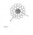
- Figure 1 illustrates a cross-section of an electric transmission cable with a compacted steel core according to the invention.
- the present invention provides a method for fabricating a core for an electric transmission cable comprising
- Figure 1 is a cross-section of an electric transmission cable according to the invention showing a compacted core section (a) and a conductor section (b).
- the wires of the core are stranded and compacted.
- the conductor wires are stranded around the compacted core.
- the step of compacting the core may be in line with the step of stranding the core wires, which means that the compacting of the core is done immediately after stranding the wires, preferably in the same line.
- Compacting of the core is done by rolling. Rolling is a technique where the core wires pass along a series of compacting rolls or Turks heads.
- the compacting of the core may be done by means of compacting rolls, because the wires will heat up less compared to die drawing, thereby less influencing the core's mechanical properties, e.g. tensile strength.
- Die drawing is a technique used to produce flexible metal wire by drawing the material through a series of dies (holes) of decreasing size. Person skilled in the art will understand that both techniques may also be mixed depending on the wire material and its compacting resistance and the type of coating used and its compacting degree.
- the number of wires is between 5 and 25, and preferably 7 or 19.
- Most standard electric transmission cables have a core of 7 or 19 wires. They may be helicoidally twisted and axially aligned. In the case of 7 wires the core strand has a 1+6 construction, and in the case of 19 wires the core strand has a 1+6+12 SZ or ZS construction.
- the wires of the core are made of high-carbon steel.
- a high-carbon steel has a steel composition along the following lines: a carbon content ranging from 0.30 % to 1.15 %, a manganese content ranging from 0.10 % to 1.10 %, a silicon content ranging from 0.10 % to 0.90 %, sulfur and phosphorous contents being limited to 0.15 %, preferably to 0.10 % or even lower; additional micro-alloying elements such as chromium (up to 0.20 % - 0.40 %), copper (up to 0.20 %) and vanadium (up to 0.30 %) may be added. All percentages are percentages by weight.
- the core wires are coated individually to avoid corrosion in between the wires due to water leakage.
- This coating is any coating keeping sufficient coating properties after compacting and is selected from zinc, zinc-aluminum or zinc-aluminum-magnesium types of alloy.
- a zinc-aluminum coating is a preferred coating.
- This coating on the steel core has an aluminum content ranging from 2 per cent to 12 per cent, e.g. ranging from 3 per cent to 11 per cent, with a preferable composition around the eutectoid position : Al about 5 per cent.
- the zinc alloy coating further has a wetting agent such as lanthanum or cerium in an amount less than 0.1 per cent of the zinc alloy.
- the remainder of the coating is zinc and unavoidable impurities.
- the zinc aluminum coating has a better overall corrosion resistance than zinc. In contrast with zinc, the zinc aluminum coating is temperature resistant and withstands the pre-annealing process of ACSS. Still in contrast with zinc, there is no flaking with the zinc aluminum alloy when exposed to high temperatures. All percentages are percentages by weight.
- Zinc aluminum magnesium coatings also offer an increased corrosion resistance.
- the aluminum amount ranges from 0.1 per cent to 12 per cent and the magnesium amount ranges from 0.1 per cent to 5.0 per cent.
- the balance of the composition is zinc and unavoidable impurities.
- An example is an aluminum content ranging from 4 per cent to 7.5 per cent, and a magnesium content ranging from 0.25 to 0.75 per cent. All percentages are percentages by weight.
- the weight of the coating on the steel wires is more than 100 g/m 2 , and preferably more than 200 g/m 2 .
- the method may further comprise the step of additionally coating the compacted core. After compacting, it may be useful to coat the core again with preferably zinc, zinc-aluminum or zinc-aluminum-magnesium types of alloy.
- the second coating's requirements are less severe compared to the first, as the second coating does not have to withstand a compacting step.
- the method may further comprise the step of forming conductors surrounding the core.
- the conductors may be made of, but not limited to aluminum, aluminum alloy, aluminum-magnesium-silicon alloy, aluminum composite.
- the conductor may be compacted or made from trapezoidal shaped compacted wires.
- a compacted conductor may also be obtained by forming the conductor wires already in a trapezoidal shape before stranding.
- the present invention provides an electric transmission cable comprising
- the electric transmission cable may be, but may not be limited to AAC (All Aluminum Conductor), AAAC (All Aluminum Alloy conductor), ACSR (Aluminum Conductor Steel Reinforced), ACSS (Aluminum Conductor Steel Supported), ACAR (Aluminum Conductor Aluminum-Alloy Reinforced), AACSR (Aluminum Alloy Conductor Steel Reinforced), AAC/TW (All Aluminum Conductor/Trapezoidal Wires), AAAC/TW (All Aluminum Alloy conductor/Trapezoidal Wires), ACSR/TW (Aluminum Conductor Steel Reinforced/Trapezoidal Wires), ACSS/TW (Aluminum Conductor Steel Supported/Trapezoidal Wires).
- AAC All Aluminum Conductor
- AAAC All Aluminum Alloy conductor
- ACSR Al Conductor Steel Reinforced
- ACSS/TW Alinum Conductor Steel Supported/Trapezoidal Wires.
- the steel core of the electric transmission cable may be a 7 wires steel core with a diameter decreased up to 10% when compared to the non-compacted 7 wires steel core.
- the air gaps that are present in the non-compacted steel core may be filled, although intermediate diameter reductions are also possible depending on cable requirements.
- this configuration may allow keeping the same steel core section and, because of this, the same final ultimate tensile strength (UTS) may be guaranteed, without steel wire tensile strength changes. Consequently, the conductor design can be tailored by reducing its final diameter, while maintaining the conductor current carrying capacity, or by keeping its conventional diameter, thereby increasing the conductor section and its current carrying capacity.
- the steel core of the electric transmission cable may be a 7 wires steel core with a section increased up to 20% while maintaining its conventional diameter.
- the air gaps that are present in the non-compacted steel core may be filled, although intermediate diameter reductions are also possible depending on cable requirements.
- this configuration may allow to increase linearly the UTS of the core without steel wire tensile strength changes.
- the core section's weight may increase. Consequently, conductor design can be modified by increasing its diameter, thereby increasing the conductor current carrying capacity, or by keeping its conventional diameter, thereby keeping the conventional conductor section and its current carrying capacity. In this case the conductor may have a higher safety coefficient due to its increased steel section in comparison with the conductor section.
- the steel core of the electric transmission cable may be a 19 wires steel core with a diameter decreased up to 7% when compared to the non-compacted 19 wires steel core.
- the air gaps that are present in the non-compacted steel core may be filled, although intermediate diameter reductions are also possible depending on cable requirements.
- this configuration may allow keeping the same steel core section and, because of this, the same final ultimate tensile strength (UTS) may be guaranteed, without steel wire tensile strength changes. Consequently, the conductor design can be tailored by reducing its final diameter, while maintaining the conductor current carrying capacity, or by keeping its conventional diameter, thereby increasing the conductor section and its current carrying capacity.
- the steel core of the electric transmission cable may be a 19 wires steel core with a section increased up to 14% while maintaining its conventional diameter.
- the air gaps that are present in the non-compacted steel core may be filled, although intermediate diameter reductions are also possible depending on cable requirements.
- this configuration may allow to increase linearly the UTS of the core without steel wire tensile strength changes.
- the core section's weight may increase. Consequently, conductor design can be modified by increasing its diameter, thereby increasing the conductor current carrying capacity, or by keeping its conventional diameter, thereby keeping the conventional conductor section and its current carrying capacity. In this latter case the conductor may have a higher safety coefficient due to the increased steel section in comparison with the conductor section.
- the openings between the outer wires of the steel core are reduced or have disappeared.
- the steel core when subjected to a tensile load has less or no structural elongation.
- This absence or reduction in structural elongation results in a reduced total elongation and in an increased E-modulus of the steel core.
- this E-modulus may be increased by more than 10%, by more than 15%, or by more than 20%.
- a compacted steel core is much stiffer than a non-compacted one, which results in a reduced sag. Reductions in the sag of up to 10% and more may be possible.
- An electric transmission cable in accordance with the present invention is operable at higher electrical outputs than traditional cables when keeping a conventional diameter. If conventional electrical outputs are requested, its reduced diameter diminishes the effects of wind, ice or snow. In both cases the main mechanical, corrosion and thermal properties of the individual core wires are improved or kept. Additionally, due to the high degree of compaction of the core, the electric loses due to air gaps in between the core wires may be reduced, resulting in more effective electric power conduction.
Landscapes
- Non-Insulated Conductors (AREA)
- Ropes Or Cables (AREA)
- Wire Processing (AREA)
Description
- The present invention relates to the field of electric transmission cables and methods of fabricating it.
- Nowadays an enormous amount of electric energy power is transported and consumed. A current trend is to buy electricity where it is cheapest, resulting in an enormous amount of electricity transport over large distances by using the existing electricity distribution network.
- Because the capacity of the existing electricity distribution network is getting insufficient, it should be upgraded in the near future.
- An obvious solution could be building new additional electric power transmission lines, but economical and ecological reasons prevent this in a lot of cases.
- Another solution could be increasing the amount of electrical current flowing through the existing lines. However, as heat generation increases quadratic with the current, the nominal operating temperature rises then from about 50°C up to about 200°C and even 300°C. The existing electric power transmission lines equipped with traditional ACSR (aluminum conductor steel reinforced) cables are not suitable for operating at these temperatures. With rising temperatures, the conductors (mostly aluminum) which also partially mechanically support the cable, loose their mechanical strength leading to significant sag. In addition, the zinc of the galvanized steel wires of the core diffuses and forms a brittle iron-zinc layer causing flaking and decreasing corrosion resistance. In case of ACSS (aluminum conductor steel supported) cables, where the aluminum conductors do not mechanically support the cable, thermal expansion of the steel core leads to significant sag at high operating temperatures.
- Another solution could lie in using an increased conductor section to increase the conductor current carrying capacity. This would obviously result in increased cable diameter, thereby increasing ice and wind loading. Higher ice and wind loading increases pole/tower loading and oblige shorter design spans. To be able to increase the conductor section without increasing the cable diameter, trapezoidal shaped wires and compacting techniques are used to compact the conductor section.
US patent no. 5243137 discloses an electrical overhead transmission conductor cable formed of trapezoidal cross section conductors wires for improved vibration performance characteristics. - As described in "Transmission conductors - A review of the design and selection criteria" by Southwire Communications (January, 31, 2003), compact conductors can be manufactured by passing the stranded cable through powerful compacting rolls or a compacting die. Another technique as described is stranding trapezoidal shape wired conductors. Their shape results also in less void area in between the conductors and a reduced cable diameter.
- However, since electricity consumption is still increasing, the need is clearly felt for an electric transmission cable either with the same cable diameter compared to the existing electric transmission cables, but having an increased conductor current carrying capacity, either with a smaller cable diameter, but keeping at least the same conductor current carrying capacity. Furthermore, the load carrying core should have at least the same tensile strength as compared to conventional cores and at least the same corrosion resistance.
- In accordance with the present invention, an improved core for electric transmission cable and method of fabricating it is now presented to overcome all drawbacks of the prior art and to fulfill this need.
- The invention is directed to a method for fabricating a core for an electric transmission cable comprising
- providing wires made of high-carbon steel and in a number of between 5 and 25, and coating them with zinc, zinc-aluminum or zinc-aluminum-magnesium types of alloy, wherein the weight of the coating on the wires is more than 100 g/m2,
- stranding the coated wires thereby forming a core,
- compacting the core by means of compacting rolls or by means of Turks heads.
- The number of wires in the core is preferably 7 or 19.
- The step of compacting may be preferably in line with the step of stranding.
- The core may be made from trapezoidal shaped compacted wires.
- The weight of the coating on the steel wires is preferably more than 200 g/m2.
- The method may further comprise the step of additionally coating the compacted core.
- The method may further comprise the step of forming conductors surrounding the compacted core.
- The conductors may be made of, but not limited to aluminum, aluminum alloy, aluminum-magnesium-silicon alloy, aluminum composite.
- The conductors may be compacted or made from trapezoidal shaped compacted wires.
- Further, the invention is directed to an electric transmission cable comprising
- a cable core having individually coated and stranded wires made of high-carbon steel and in a number of between 5 and 25,
- and conductors surrounding the core,
- The compacted core may be surrounded with an additional coating.
- The conductors may be made of aluminum, aluminum alloy, aluminum-magnesium-silicon alloy, aluminum composite.
- The conductors may be compacted or made from trapezoidal shaped compacted wires.
- The weight of the coating on the wires is preferably more than 200 g/m2.
- The wires of said cable core is preferably in a number of 7or 19.
-
Figure 1 illustrates a cross-section of an electric transmission cable with a compacted steel core according to the invention. - A person skilled in the art will understood that the embodiments described below are merely illustrative in accordance with the present invention and not limiting the intended scope of the invention. Other embodiments may also be considered.
- As a first object, the present invention provides a method for fabricating a core for an electric transmission cable comprising
- providing at least two wires and coating them
- stranding the coated wires thereby forming a core
- compacting the core
- As already described above, compacted conductors are known in the state of the art and even widely applied. However, prior art never suggested to compact the core of an electric transmission cable, as persons skilled in the art would expect that, when compacting the core, thereby deforming individually coated wires to the degree they loose their circularity, the coating would be significantly damaged, leading to diminished parameters such as loss of corrosion resistance. In accordance with the present invention however, a cable core from individually coated and stranded wires can indeed be compacted when using a suitable coating and performing the compacting step using suitable processing parameters. When matching coating and compacting, the coating corrosion resistance is not decreased when compared to standard non compacted or non trapezoidal wire shapes.
-
Figure 1 is a cross-section of an electric transmission cable according to the invention showing a compacted core section (a) and a conductor section (b). - After coating, the wires of the core are stranded and compacted. In parallel, the conductor wires are stranded around the compacted core. The step of compacting the core may be in line with the step of stranding the core wires, which means that the compacting of the core is done immediately after stranding the wires, preferably in the same line.
- Compacting of the core is done by rolling. Rolling is a technique where the core wires pass along a series of compacting rolls or Turks heads.
- In a preferred embodiment, the compacting of the core may be done by means of compacting rolls, because the wires will heat up less compared to die drawing, thereby less influencing the core's mechanical properties, e.g. tensile strength. The risk of loosing wire coating and/or of damaging the wire coating is also smaller compared to die drawing. Die drawing is a technique used to produce flexible metal wire by drawing the material through a series of dies (holes) of decreasing size. Person skilled in the art will understand that both techniques may also be mixed depending on the wire material and its compacting resistance and the type of coating used and its compacting degree.
- The number of wires is between 5 and 25, and preferably 7 or 19. Most standard electric transmission cables have a core of 7 or 19 wires. They may be helicoidally twisted and axially aligned. In the case of 7 wires the core strand has a 1+6 construction, and in the case of 19 wires the core strand has a 1+6+12 SZ or ZS construction.
- The wires of the core are made of high-carbon steel. A high-carbon steel has a steel composition along the following lines: a carbon content ranging from 0.30 % to 1.15 %, a manganese content ranging from 0.10 % to 1.10 %, a silicon content ranging from 0.10 % to 0.90 %, sulfur and phosphorous contents being limited to 0.15 %, preferably to 0.10 % or even lower; additional micro-alloying elements such as chromium (up to 0.20 % - 0.40 %), copper (up to 0.20 %) and vanadium (up to 0.30 %) may be added. All percentages are percentages by weight.
- The core wires are coated individually to avoid corrosion in between the wires due to water leakage. This coating is any coating keeping sufficient coating properties after compacting and is selected from zinc, zinc-aluminum or zinc-aluminum-magnesium types of alloy.
- A zinc-aluminum coating is a preferred coating. This coating on the steel core has an aluminum content ranging from 2 per cent to 12 per cent, e.g. ranging from 3 per cent to 11 per cent, with a preferable composition around the eutectoid position : Al about 5 per cent. The zinc alloy coating further has a wetting agent such as lanthanum or cerium in an amount less than 0.1 per cent of the zinc alloy. The remainder of the coating is zinc and unavoidable impurities. The zinc aluminum coating has a better overall corrosion resistance than zinc. In contrast with zinc, the zinc aluminum coating is temperature resistant and withstands the pre-annealing process of ACSS. Still in contrast with zinc, there is no flaking with the zinc aluminum alloy when exposed to high temperatures. All percentages are percentages by weight.
- Zinc aluminum magnesium coatings also offer an increased corrosion resistance. In a preferable zinc aluminum magnesium coating the aluminum amount ranges from 0.1 per cent to 12 per cent and the magnesium amount ranges from 0.1 per cent to 5.0 per cent. The balance of the composition is zinc and unavoidable impurities. An example is an aluminum content ranging from 4 per cent to 7.5 per cent, and a magnesium content ranging from 0.25 to 0.75 per cent. All percentages are percentages by weight.
- The weight of the coating on the steel wires is more than 100 g/m2, and preferably more than 200 g/m2.
- In a further embodiment of the invention, the method may further comprise the step of additionally coating the compacted core. After compacting, it may be useful to coat the core again with preferably zinc, zinc-aluminum or zinc-aluminum-magnesium types of alloy. A person skilled in the art will understand that the second coating's requirements are less severe compared to the first, as the second coating does not have to withstand a compacting step.
- The method may further comprise the step of forming conductors surrounding the core.
- The conductors may be made of, but not limited to aluminum, aluminum alloy, aluminum-magnesium-silicon alloy, aluminum composite.
- In a further embodiment of the invention, the conductor may be compacted or made from trapezoidal shaped compacted wires. As already described above, it is known in the art and widely applied to compact the conductor to reduce the cable diameter and keep the same conductor current carrying capacity, or to keep the same cable diameter compared to non-compacted conductor cables and at the same time increase the conductor section. A compacted conductor may also be obtained by forming the conductor wires already in a trapezoidal shape before stranding. By combining a compacted core and a compacted conductor, the cable diameter may be significantly reduced or, when keeping the conventional cable diameter, the conductor section may be significantly increased.
- As a second object, the present invention provides an electric transmission cable comprising
- a cable core having at least two individually coated and stranded wires
- and conductors surrounding the core,
- In accordance with the invention, the electric transmission cable may be, but may not be limited to AAC (All Aluminum Conductor), AAAC (All Aluminum Alloy conductor), ACSR (Aluminum Conductor Steel Reinforced), ACSS (Aluminum Conductor Steel Supported), ACAR (Aluminum Conductor Aluminum-Alloy Reinforced), AACSR (Aluminum Alloy Conductor Steel Reinforced), AAC/TW (All Aluminum Conductor/Trapezoidal Wires), AAAC/TW (All Aluminum Alloy conductor/Trapezoidal Wires), ACSR/TW (Aluminum Conductor Steel Reinforced/Trapezoidal Wires), ACSS/TW (Aluminum Conductor Steel Supported/Trapezoidal Wires).
- In an embodiment of the invention, the steel core of the electric transmission cable may be a 7 wires steel core with a diameter decreased up to 10% when compared to the non-compacted 7 wires steel core. The air gaps that are present in the non-compacted steel core may be filled, although intermediate diameter reductions are also possible depending on cable requirements. Concomitantly, this configuration may allow keeping the same steel core section and, because of this, the same final ultimate tensile strength (UTS) may be guaranteed, without steel wire tensile strength changes. Consequently, the conductor design can be tailored by reducing its final diameter, while maintaining the conductor current carrying capacity, or by keeping its conventional diameter, thereby increasing the conductor section and its current carrying capacity.
- In an embodiment of the invention, the steel core of the electric transmission cable may be a 7 wires steel core with a section increased up to 20% while maintaining its conventional diameter. The air gaps that are present in the non-compacted steel core may be filled, although intermediate diameter reductions are also possible depending on cable requirements. At the same time, this configuration may allow to increase linearly the UTS of the core without steel wire tensile strength changes. Obviously, the core section's weight may increase. Consequently, conductor design can be modified by increasing its diameter, thereby increasing the conductor current carrying capacity, or by keeping its conventional diameter, thereby keeping the conventional conductor section and its current carrying capacity. In this case the conductor may have a higher safety coefficient due to its increased steel section in comparison with the conductor section.
- In an embodiment of the invention, the steel core of the electric transmission cable may be a 19 wires steel core with a diameter decreased up to 7% when compared to the non-compacted 19 wires steel core. The air gaps that are present in the non-compacted steel core may be filled, although intermediate diameter reductions are also possible depending on cable requirements. Concomitantly, this configuration may allow keeping the same steel core section and, because of this, the same final ultimate tensile strength (UTS) may be guaranteed, without steel wire tensile strength changes. Consequently, the conductor design can be tailored by reducing its final diameter, while maintaining the conductor current carrying capacity, or by keeping its conventional diameter, thereby increasing the conductor section and its current carrying capacity.
- In an embodiment of the invention, the steel core of the electric transmission cable may be a 19 wires steel core with a section increased up to 14% while maintaining its conventional diameter. The air gaps that are present in the non-compacted steel core may be filled, although intermediate diameter reductions are also possible depending on cable requirements. At the same time, this configuration may allow to increase linearly the UTS of the core without steel wire tensile strength changes. Obviously, the core section's weight may increase. Consequently, conductor design can be modified by increasing its diameter, thereby increasing the conductor current carrying capacity, or by keeping its conventional diameter, thereby keeping the conventional conductor section and its current carrying capacity. In this latter case the conductor may have a higher safety coefficient due to the increased steel section in comparison with the conductor section.
- Due to the compacting of the steel core, the openings between the outer wires of the steel core are reduced or have disappeared. As a result, the steel core when subjected to a tensile load has less or no structural elongation. This absence or reduction in structural elongation results in a reduced total elongation and in an increased E-modulus of the steel core. By compacting, this E-modulus may be increased by more than 10%, by more than 15%, or by more than 20%. Hence, a compacted steel core is much stiffer than a non-compacted one, which results in a reduced sag. Reductions in the sag of up to 10% and more may be possible.
- An electric transmission cable in accordance with the present invention is operable at higher electrical outputs than traditional cables when keeping a conventional diameter. If conventional electrical outputs are requested, its reduced diameter diminishes the effects of wind, ice or snow. In both cases the main mechanical, corrosion and thermal properties of the individual core wires are improved or kept. Additionally, due to the high degree of compaction of the core, the electric loses due to air gaps in between the core wires may be reduced, resulting in more effective electric power conduction.
Claims (14)
- A method for fabricating an electric transmission cable comprising- providing wires made of high-carbon steel and in a number of between 5 and 25, and coating them with zinc, zinc-aluminum or zinc-aluminum-magnesium types of alloy, wherein the weight of the coating on the wires is more than 100 g/m2,- stranding the coated wires thereby forming a core,- compacting the core by means of compacting rolls or by means of Turks heads.
- A method according to claim 1, wherein the weight of the coating on the wires is more than 200 g/m2.
- A method according to claim 1 or 2, further comprising the step of additionally coating the compacted core.
- A method according to any of the preceding claims, further comprising the step of forming conductors surrounding the core.
- A method according to claim 4, wherein the conductors are compacted or made from trapezoidal shaped compacted wires.
- A method according to any one of the preceding claims, wherein the wires are in a number of 7.
- A method according to any one of claims 1 to 5, wherein the wires are in a number of 19.
- An electric transmission cable comprising- a cable core having individually coated and stranded wires made of high-carbon steel and in a number of between 5 and 25,- and conductors surrounding the core,wherein the core is compacted, and the wires are coated with zinc, zinc-aluminum or zinc-aluminum-magnesium types of alloy which keeps sufficient coating properties after compacting, wherein a weight of the coating on the wires is more than 100 g/m2.
- An electric transmission cable according to claim 8, wherein the compacted core is surrounded with an additional coating.
- An electric transmission cable according to claim 8 or 9, wherein the conductors are made of aluminum, aluminum alloy, aluminum-magnesium-silicon alloy, aluminum composite.
- An electric transmission cable according to any one of claims 8 to 10, wherein the conductors are compacted or made from trapezoidal shaped compacted wires.
- An electric transmission cable according any one of claims 8 to 11, wherein the weight of the coating on the wires is more than 200 g/m2.
- An electric transmission cable according any one of claims 8 to 12, wherein the wires of said cable core are in a number of 7.
- An electric transmission cable according any one of claims 8 to 12, wherein the wires of said cable core are in a number of 19.
Priority Applications (2)
| Application Number | Priority Date | Filing Date | Title |
|---|---|---|---|
| PL08701532T PL2118907T3 (en) | 2007-02-16 | 2008-01-16 | An improved steel core for an electric transmission cable and method of fabricating it |
| EP08701532.7A EP2118907B1 (en) | 2007-02-16 | 2008-01-16 | An improved steel core for an electric transmission cable and method of fabricating it |
Applications Claiming Priority (3)
| Application Number | Priority Date | Filing Date | Title |
|---|---|---|---|
| EP07003310 | 2007-02-16 | ||
| EP08701532.7A EP2118907B1 (en) | 2007-02-16 | 2008-01-16 | An improved steel core for an electric transmission cable and method of fabricating it |
| PCT/EP2008/050467 WO2008098811A1 (en) | 2007-02-16 | 2008-01-16 | An improved steel core for an electric transmission cable and method of fabricating it |
Publications (2)
| Publication Number | Publication Date |
|---|---|
| EP2118907A1 EP2118907A1 (en) | 2009-11-18 |
| EP2118907B1 true EP2118907B1 (en) | 2016-01-13 |
Family
ID=38198143
Family Applications (1)
| Application Number | Title | Priority Date | Filing Date |
|---|---|---|---|
| EP08701532.7A Not-in-force EP2118907B1 (en) | 2007-02-16 | 2008-01-16 | An improved steel core for an electric transmission cable and method of fabricating it |
Country Status (9)
| Country | Link |
|---|---|
| US (1) | US8822827B2 (en) |
| EP (1) | EP2118907B1 (en) |
| CN (1) | CN101606207A (en) |
| BR (1) | BRPI0807644A2 (en) |
| CA (1) | CA2675253C (en) |
| MX (1) | MX2009007424A (en) |
| PL (1) | PL2118907T3 (en) |
| RU (1) | RU2009134494A (en) |
| WO (1) | WO2008098811A1 (en) |
Families Citing this family (23)
| Publication number | Priority date | Publication date | Assignee | Title |
|---|---|---|---|---|
| CN103038838B (en) * | 2010-04-19 | 2016-08-31 | 戴纳普斯公司 | For the method changing the electrical conductivity of material |
| US8568015B2 (en) | 2010-09-23 | 2013-10-29 | Willis Electric Co., Ltd. | Decorative light string for artificial lighted tree |
| WO2013089723A1 (en) * | 2011-12-15 | 2013-06-20 | Otis Elevator Company | Elevator system belt |
| US9909419B2 (en) * | 2012-03-09 | 2018-03-06 | Nv Bekaert Sa | Strand, cable bolt and its installation |
| US10206530B2 (en) | 2012-05-08 | 2019-02-19 | Willis Electric Co., Ltd. | Modular tree with locking trunk |
| US9044056B2 (en) | 2012-05-08 | 2015-06-02 | Willis Electric Co., Ltd. | Modular tree with electrical connector |
| US9179793B2 (en) | 2012-05-08 | 2015-11-10 | Willis Electric Co., Ltd. | Modular tree with rotation-lock electrical connectors |
| US9140438B2 (en) | 2013-09-13 | 2015-09-22 | Willis Electric Co., Ltd. | Decorative lighting with reinforced wiring |
| US10267464B2 (en) | 2015-10-26 | 2019-04-23 | Willis Electric Co., Ltd. | Tangle-resistant decorative lighting assembly |
| US9157588B2 (en) | 2013-09-13 | 2015-10-13 | Willis Electric Co., Ltd | Decorative lighting with reinforced wiring |
| DE102013222529A1 (en) * | 2013-11-06 | 2015-05-07 | Leoni Kabel Holding Gmbh | Stranded conductor and method for producing stranded conductors |
| US10068683B1 (en) | 2014-06-06 | 2018-09-04 | Southwire Company, Llc | Rare earth materials as coating compositions for conductors |
| USD779440S1 (en) | 2014-08-07 | 2017-02-21 | Henkel Ag & Co. Kgaa | Overhead transmission conductor cable |
| USD815047S1 (en) | 2014-09-25 | 2018-04-10 | Conway Electric, LLC | Overbraided electrical cord with X pattern |
| EP3211642A1 (en) * | 2016-02-23 | 2017-08-30 | LEONI Kabel Holding GmbH | Data cable and stranded conductor |
| RU174486U1 (en) * | 2017-06-05 | 2017-10-17 | Общество с ограниченной ответственностью "Камский кабель" | POWER CABLE WITH A CURRENT CONDUCTING RESIDENT FROM ALUMINUM ALLOY |
| RU180434U1 (en) * | 2018-01-22 | 2018-06-14 | Сергей Иванович Чуловский | Flexible power cable with conductive conductors made of aluminum alloy |
| RU184351U1 (en) * | 2018-07-11 | 2018-10-23 | Акционерное общество "Научно-исследовательский, проектно-конструкторский и технологический кабельный институт (НИКИ) г.Томск с опытным производством" | Power cable |
| RU188730U1 (en) * | 2018-09-19 | 2019-04-23 | Общество с ограниченной ответственностью "Камский кабель" | FLEXIBLE POWER CABLE |
| CN110055781A (en) * | 2019-05-21 | 2019-07-26 | 贵州钢绳股份有限公司 | A kind of diameter 45mm bursts of compactings non-rotating cable construction design method |
| CN114171293B (en) * | 2020-09-10 | 2024-04-23 | 北京小米移动软件有限公司 | Coil assembly and terminal |
| WO2022129067A1 (en) * | 2020-12-17 | 2022-06-23 | Nv Bekaert Sa | Compacted steel strand with cladded core |
| CN113355602A (en) * | 2021-06-03 | 2021-09-07 | 全球能源互联网研究院有限公司 | Core wire material for overhead conductor and preparation method thereof |
Family Cites Families (8)
| Publication number | Priority date | Publication date | Assignee | Title |
|---|---|---|---|---|
| FR766758A (en) * | 1933-05-25 | 1934-07-03 | ||
| US3131469A (en) * | 1960-03-21 | 1964-05-05 | Tyler Wayne Res Corp | Process of producing a unitary multiple wire strand |
| JPS5951682B2 (en) | 1978-05-12 | 1984-12-15 | 古河電気工業株式会社 | Manufacturing method of compressed steel core aluminum stranded wire |
| US5260516A (en) * | 1992-04-24 | 1993-11-09 | Ceeco Machinery Manufacturing Limited | Concentric compressed unilay stranded conductors |
| US5243137A (en) * | 1992-06-25 | 1993-09-07 | Southwire Company | Overhead transmission conductor |
| US6307156B1 (en) * | 1997-05-02 | 2001-10-23 | General Science And Technology Corp. | High flexibility and heat dissipating coaxial cable |
| US7604860B2 (en) * | 2004-05-25 | 2009-10-20 | Korea Sangsa Co., Ltd. | High tensile nonmagnetic stainless steel wire for overhead electric conductor, low loss overhead electric conductor using the wire, and method of manufacturing the wire and overhead electric conductor |
| US7093416B2 (en) * | 2004-06-17 | 2006-08-22 | 3M Innovative Properties Company | Cable and method of making the same |
-
2008
- 2008-01-16 US US12/522,309 patent/US8822827B2/en not_active Expired - Fee Related
- 2008-01-16 BR BRPI0807644-8A2A patent/BRPI0807644A2/en not_active IP Right Cessation
- 2008-01-16 PL PL08701532T patent/PL2118907T3/en unknown
- 2008-01-16 CN CNA2008800047890A patent/CN101606207A/en active Pending
- 2008-01-16 WO PCT/EP2008/050467 patent/WO2008098811A1/en active Application Filing
- 2008-01-16 MX MX2009007424A patent/MX2009007424A/en active IP Right Grant
- 2008-01-16 EP EP08701532.7A patent/EP2118907B1/en not_active Not-in-force
- 2008-01-16 CA CA2675253A patent/CA2675253C/en not_active Expired - Fee Related
- 2008-01-16 RU RU2009134494/07A patent/RU2009134494A/en unknown
Also Published As
| Publication number | Publication date |
|---|---|
| US20090308637A1 (en) | 2009-12-17 |
| EP2118907A1 (en) | 2009-11-18 |
| MX2009007424A (en) | 2009-07-17 |
| CA2675253C (en) | 2016-02-23 |
| WO2008098811A1 (en) | 2008-08-21 |
| CA2675253A1 (en) | 2008-08-21 |
| US8822827B2 (en) | 2014-09-02 |
| CN101606207A (en) | 2009-12-16 |
| RU2009134494A (en) | 2011-03-27 |
| BRPI0807644A2 (en) | 2014-06-10 |
| PL2118907T3 (en) | 2016-06-30 |
Similar Documents
| Publication | Publication Date | Title |
|---|---|---|
| EP2118907B1 (en) | An improved steel core for an electric transmission cable and method of fabricating it | |
| USRE49941E1 (en) | Rating an enhanced strength conductor | |
| RU2386183C1 (en) | Composite bearing core for external current-conducting strands of overhead high-voltage power transmission line wires and method of its production | |
| Thrash | Transmission conductors–A review of the design and selection criteria | |
| WO2015194221A1 (en) | Overhead transmission conductor | |
| EP1488488A1 (en) | Method for application of wire system with mechanical support wire and current conducting wire for transmission line | |
| CN111263824A (en) | Stranded conductor for insulated wire, flexible wire and cable | |
| CA1045222A (en) | Aluminum alloy composite electrical conductor | |
| CN101174490A (en) | Low-sag soft aluminum conducting wire | |
| KR100602291B1 (en) | Gap-type overhead transmission line & manufacturing thereof | |
| Thrash | ACSS/TW-an improved conductor for upgrading existing lines or new construction | |
| CN112117024B (en) | Lightweight corrosion-resistant energy-saving aluminum conductor, preparation method thereof and medium-voltage power cable | |
| RU113061U1 (en) | Lightning protection cable for air transmission lines | |
| Thrash | ACSS/TW-An improved high temperature conductor for upgrading existing lines or new construction | |
| CN111816349B (en) | Ultrahigh-conductivity aluminum-clad steel strand and production process thereof | |
| JP2014232638A (en) | Steel core aluminum twisted wire | |
| Karabay | ACSS/TW aerial high-temperature bare conductors as a remedy for increasing transmission line capacity and determination of processing parameters for manufacturing | |
| EP1118397A1 (en) | A deformed metal composite wire | |
| RU2792217C1 (en) | Self-supporting insulated wire | |
| CN214271463U (en) | Hot galvanizing epoxy coating monofilament coating prestress steel strand | |
| JP2001043740A (en) | Overhead transmission line | |
| KR20150071692A (en) | Ultra high strength coated steel wire for overhead transmission and distribution conductor | |
| JP2014002863A (en) | Steel core aluminum stranded wire and method for manufacturing the same | |
| CN111180136B (en) | Flexible stranded conductor manufacturing process and stranded conductor | |
| RU2738209C1 (en) | Lightning protection cable (versions) |
Legal Events
| Date | Code | Title | Description |
|---|---|---|---|
| PUAI | Public reference made under article 153(3) epc to a published international application that has entered the european phase |
Free format text: ORIGINAL CODE: 0009012 |
|
| 17P | Request for examination filed |
Effective date: 20090623 |
|
| AK | Designated contracting states |
Kind code of ref document: A1 Designated state(s): AT BE BG CH CY CZ DE DK EE ES FI FR GB GR HR HU IE IS IT LI LT LU LV MC MT NL NO PL PT RO SE SI SK TR |
|
| DAX | Request for extension of the european patent (deleted) | ||
| 17Q | First examination report despatched |
Effective date: 20150323 |
|
| GRAP | Despatch of communication of intention to grant a patent |
Free format text: ORIGINAL CODE: EPIDOSNIGR1 |
|
| INTG | Intention to grant announced |
Effective date: 20150918 |
|
| GRAS | Grant fee paid |
Free format text: ORIGINAL CODE: EPIDOSNIGR3 |
|
| GRAA | (expected) grant |
Free format text: ORIGINAL CODE: 0009210 |
|
| AK | Designated contracting states |
Kind code of ref document: B1 Designated state(s): AT BE BG CH CY CZ DE DK EE ES FI FR GB GR HR HU IE IS IT LI LT LU LV MC MT NL NO PL PT RO SE SI SK TR |
|
| REG | Reference to a national code |
Ref country code: GB Ref legal event code: FG4D Ref country code: NL Ref legal event code: FP |
|
| REG | Reference to a national code |
Ref country code: CH Ref legal event code: EP |
|
| REG | Reference to a national code |
Ref country code: IE Ref legal event code: FG4D Ref country code: FR Ref legal event code: PLFP Year of fee payment: 9 |
|
| REG | Reference to a national code |
Ref country code: AT Ref legal event code: REF Ref document number: 770992 Country of ref document: AT Kind code of ref document: T Effective date: 20160215 |
|
| REG | Reference to a national code |
Ref country code: DE Ref legal event code: R096 Ref document number: 602008041992 Country of ref document: DE |
|
| PGFP | Annual fee paid to national office [announced via postgrant information from national office to epo] |
Ref country code: DE Payment date: 20160210 Year of fee payment: 9 |
|
| REG | Reference to a national code |
Ref country code: LT Ref legal event code: MG4D |
|
| PG25 | Lapsed in a contracting state [announced via postgrant information from national office to epo] |
Ref country code: BE Free format text: LAPSE BECAUSE OF NON-PAYMENT OF DUE FEES Effective date: 20160131 |
|
| PGFP | Annual fee paid to national office [announced via postgrant information from national office to epo] |
Ref country code: NL Payment date: 20160210 Year of fee payment: 9 Ref country code: FR Payment date: 20160210 Year of fee payment: 9 |
|
| REG | Reference to a national code |
Ref country code: AT Ref legal event code: MK05 Ref document number: 770992 Country of ref document: AT Kind code of ref document: T Effective date: 20160113 |
|
| PG25 | Lapsed in a contracting state [announced via postgrant information from national office to epo] |
Ref country code: ES Free format text: LAPSE BECAUSE OF FAILURE TO SUBMIT A TRANSLATION OF THE DESCRIPTION OR TO PAY THE FEE WITHIN THE PRESCRIBED TIME-LIMIT Effective date: 20160113 Ref country code: GR Free format text: LAPSE BECAUSE OF FAILURE TO SUBMIT A TRANSLATION OF THE DESCRIPTION OR TO PAY THE FEE WITHIN THE PRESCRIBED TIME-LIMIT Effective date: 20160414 Ref country code: NO Free format text: LAPSE BECAUSE OF FAILURE TO SUBMIT A TRANSLATION OF THE DESCRIPTION OR TO PAY THE FEE WITHIN THE PRESCRIBED TIME-LIMIT Effective date: 20160413 Ref country code: HR Free format text: LAPSE BECAUSE OF FAILURE TO SUBMIT A TRANSLATION OF THE DESCRIPTION OR TO PAY THE FEE WITHIN THE PRESCRIBED TIME-LIMIT Effective date: 20160113 Ref country code: FI Free format text: LAPSE BECAUSE OF FAILURE TO SUBMIT A TRANSLATION OF THE DESCRIPTION OR TO PAY THE FEE WITHIN THE PRESCRIBED TIME-LIMIT Effective date: 20160113 Ref country code: IT Free format text: LAPSE BECAUSE OF FAILURE TO SUBMIT A TRANSLATION OF THE DESCRIPTION OR TO PAY THE FEE WITHIN THE PRESCRIBED TIME-LIMIT Effective date: 20160113 |
|
| REG | Reference to a national code |
Ref country code: SK Ref legal event code: T3 Ref document number: E 20685 Country of ref document: SK |
|
| PG25 | Lapsed in a contracting state [announced via postgrant information from national office to epo] |
Ref country code: LT Free format text: LAPSE BECAUSE OF FAILURE TO SUBMIT A TRANSLATION OF THE DESCRIPTION OR TO PAY THE FEE WITHIN THE PRESCRIBED TIME-LIMIT Effective date: 20160113 Ref country code: SE Free format text: LAPSE BECAUSE OF FAILURE TO SUBMIT A TRANSLATION OF THE DESCRIPTION OR TO PAY THE FEE WITHIN THE PRESCRIBED TIME-LIMIT Effective date: 20160113 Ref country code: PT Free format text: LAPSE BECAUSE OF FAILURE TO SUBMIT A TRANSLATION OF THE DESCRIPTION OR TO PAY THE FEE WITHIN THE PRESCRIBED TIME-LIMIT Effective date: 20160513 Ref country code: IS Free format text: LAPSE BECAUSE OF FAILURE TO SUBMIT A TRANSLATION OF THE DESCRIPTION OR TO PAY THE FEE WITHIN THE PRESCRIBED TIME-LIMIT Effective date: 20160513 Ref country code: AT Free format text: LAPSE BECAUSE OF FAILURE TO SUBMIT A TRANSLATION OF THE DESCRIPTION OR TO PAY THE FEE WITHIN THE PRESCRIBED TIME-LIMIT Effective date: 20160113 Ref country code: LV Free format text: LAPSE BECAUSE OF FAILURE TO SUBMIT A TRANSLATION OF THE DESCRIPTION OR TO PAY THE FEE WITHIN THE PRESCRIBED TIME-LIMIT Effective date: 20160113 |
|
| PGFP | Annual fee paid to national office [announced via postgrant information from national office to epo] |
Ref country code: SK Payment date: 20160311 Year of fee payment: 9 Ref country code: PL Payment date: 20160212 Year of fee payment: 9 |
|
| REG | Reference to a national code |
Ref country code: CH Ref legal event code: PL |
|
| REG | Reference to a national code |
Ref country code: DE Ref legal event code: R097 Ref document number: 602008041992 Country of ref document: DE |
|
| PG25 | Lapsed in a contracting state [announced via postgrant information from national office to epo] |
Ref country code: MC Free format text: LAPSE BECAUSE OF FAILURE TO SUBMIT A TRANSLATION OF THE DESCRIPTION OR TO PAY THE FEE WITHIN THE PRESCRIBED TIME-LIMIT Effective date: 20160113 Ref country code: CH Free format text: LAPSE BECAUSE OF NON-PAYMENT OF DUE FEES Effective date: 20160131 Ref country code: EE Free format text: LAPSE BECAUSE OF FAILURE TO SUBMIT A TRANSLATION OF THE DESCRIPTION OR TO PAY THE FEE WITHIN THE PRESCRIBED TIME-LIMIT Effective date: 20160113 Ref country code: DK Free format text: LAPSE BECAUSE OF FAILURE TO SUBMIT A TRANSLATION OF THE DESCRIPTION OR TO PAY THE FEE WITHIN THE PRESCRIBED TIME-LIMIT Effective date: 20160113 Ref country code: LI Free format text: LAPSE BECAUSE OF NON-PAYMENT OF DUE FEES Effective date: 20160131 |
|
| REG | Reference to a national code |
Ref country code: IE Ref legal event code: MM4A |
|
| PLBE | No opposition filed within time limit |
Free format text: ORIGINAL CODE: 0009261 |
|
| STAA | Information on the status of an ep patent application or granted ep patent |
Free format text: STATUS: NO OPPOSITION FILED WITHIN TIME LIMIT |
|
| PG25 | Lapsed in a contracting state [announced via postgrant information from national office to epo] |
Ref country code: CZ Free format text: LAPSE BECAUSE OF FAILURE TO SUBMIT A TRANSLATION OF THE DESCRIPTION OR TO PAY THE FEE WITHIN THE PRESCRIBED TIME-LIMIT Effective date: 20160113 Ref country code: RO Free format text: LAPSE BECAUSE OF FAILURE TO SUBMIT A TRANSLATION OF THE DESCRIPTION OR TO PAY THE FEE WITHIN THE PRESCRIBED TIME-LIMIT Effective date: 20160113 |
|
| 26N | No opposition filed |
Effective date: 20161014 |
|
| GBPC | Gb: european patent ceased through non-payment of renewal fee |
Effective date: 20160413 |
|
| PG25 | Lapsed in a contracting state [announced via postgrant information from national office to epo] |
Ref country code: BE Free format text: LAPSE BECAUSE OF FAILURE TO SUBMIT A TRANSLATION OF THE DESCRIPTION OR TO PAY THE FEE WITHIN THE PRESCRIBED TIME-LIMIT Effective date: 20160113 |
|
| PG25 | Lapsed in a contracting state [announced via postgrant information from national office to epo] |
Ref country code: GB Free format text: LAPSE BECAUSE OF NON-PAYMENT OF DUE FEES Effective date: 20160413 Ref country code: IE Free format text: LAPSE BECAUSE OF NON-PAYMENT OF DUE FEES Effective date: 20160116 |
|
| PG25 | Lapsed in a contracting state [announced via postgrant information from national office to epo] |
Ref country code: BG Free format text: LAPSE BECAUSE OF FAILURE TO SUBMIT A TRANSLATION OF THE DESCRIPTION OR TO PAY THE FEE WITHIN THE PRESCRIBED TIME-LIMIT Effective date: 20160413 Ref country code: SI Free format text: LAPSE BECAUSE OF FAILURE TO SUBMIT A TRANSLATION OF THE DESCRIPTION OR TO PAY THE FEE WITHIN THE PRESCRIBED TIME-LIMIT Effective date: 20160113 |
|
| REG | Reference to a national code |
Ref country code: DE Ref legal event code: R119 Ref document number: 602008041992 Country of ref document: DE |
|
| PG25 | Lapsed in a contracting state [announced via postgrant information from national office to epo] |
Ref country code: MT Free format text: LAPSE BECAUSE OF FAILURE TO SUBMIT A TRANSLATION OF THE DESCRIPTION OR TO PAY THE FEE WITHIN THE PRESCRIBED TIME-LIMIT Effective date: 20160113 |
|
| REG | Reference to a national code |
Ref country code: NL Ref legal event code: MM Effective date: 20170201 |
|
| REG | Reference to a national code |
Ref country code: SK Ref legal event code: MM4A Ref document number: E 20685 Country of ref document: SK Effective date: 20170116 |
|
| REG | Reference to a national code |
Ref country code: FR Ref legal event code: ST Effective date: 20170929 |
|
| PG25 | Lapsed in a contracting state [announced via postgrant information from national office to epo] |
Ref country code: FR Free format text: LAPSE BECAUSE OF NON-PAYMENT OF DUE FEES Effective date: 20170131 Ref country code: SK Free format text: LAPSE BECAUSE OF NON-PAYMENT OF DUE FEES Effective date: 20170116 |
|
| PG25 | Lapsed in a contracting state [announced via postgrant information from national office to epo] |
Ref country code: NL Free format text: LAPSE BECAUSE OF NON-PAYMENT OF DUE FEES Effective date: 20170201 Ref country code: DE Free format text: LAPSE BECAUSE OF NON-PAYMENT OF DUE FEES Effective date: 20170801 |
|
| PG25 | Lapsed in a contracting state [announced via postgrant information from national office to epo] |
Ref country code: CY Free format text: LAPSE BECAUSE OF FAILURE TO SUBMIT A TRANSLATION OF THE DESCRIPTION OR TO PAY THE FEE WITHIN THE PRESCRIBED TIME-LIMIT Effective date: 20160113 Ref country code: HU Free format text: LAPSE BECAUSE OF FAILURE TO SUBMIT A TRANSLATION OF THE DESCRIPTION OR TO PAY THE FEE WITHIN THE PRESCRIBED TIME-LIMIT; INVALID AB INITIO Effective date: 20080116 |
|
| PG25 | Lapsed in a contracting state [announced via postgrant information from national office to epo] |
Ref country code: LU Free format text: LAPSE BECAUSE OF NON-PAYMENT OF DUE FEES Effective date: 20160116 Ref country code: MT Free format text: LAPSE BECAUSE OF FAILURE TO SUBMIT A TRANSLATION OF THE DESCRIPTION OR TO PAY THE FEE WITHIN THE PRESCRIBED TIME-LIMIT Effective date: 20160131 Ref country code: TR Free format text: LAPSE BECAUSE OF FAILURE TO SUBMIT A TRANSLATION OF THE DESCRIPTION OR TO PAY THE FEE WITHIN THE PRESCRIBED TIME-LIMIT Effective date: 20160113 |
|
| PG25 | Lapsed in a contracting state [announced via postgrant information from national office to epo] |
Ref country code: PL Free format text: LAPSE BECAUSE OF NON-PAYMENT OF DUE FEES Effective date: 20170116 |