EP2118715B1 - Druckregelventilanordnung - Google Patents
Druckregelventilanordnung Download PDFInfo
- Publication number
- EP2118715B1 EP2118715B1 EP20080719292 EP08719292A EP2118715B1 EP 2118715 B1 EP2118715 B1 EP 2118715B1 EP 20080719292 EP20080719292 EP 20080719292 EP 08719292 A EP08719292 A EP 08719292A EP 2118715 B1 EP2118715 B1 EP 2118715B1
- Authority
- EP
- European Patent Office
- Prior art keywords
- insert
- port
- valve assembly
- plastic
- molding
- Prior art date
- Legal status (The legal status is an assumption and is not a legal conclusion. Google has not performed a legal analysis and makes no representation as to the accuracy of the status listed.)
- Not-in-force
Links
- 239000004033 plastic Substances 0.000 claims description 64
- 239000002184 metal Substances 0.000 claims description 20
- 229910052751 metal Inorganic materials 0.000 claims description 20
- 238000000034 method Methods 0.000 claims description 18
- 239000000463 material Substances 0.000 claims description 16
- 238000000465 moulding Methods 0.000 claims description 15
- 239000012530 fluid Substances 0.000 claims description 8
- 229910000831 Steel Inorganic materials 0.000 claims description 4
- 239000010959 steel Substances 0.000 claims description 4
- 239000004677 Nylon Substances 0.000 claims description 3
- 229920001778 nylon Polymers 0.000 claims description 3
- 229910001369 Brass Inorganic materials 0.000 claims description 2
- 239000010951 brass Substances 0.000 claims description 2
- 238000000748 compression moulding Methods 0.000 claims description 2
- 239000011521 glass Substances 0.000 claims description 2
- 238000001746 injection moulding Methods 0.000 claims description 2
- 239000008358 core component Substances 0.000 claims 1
- 230000015572 biosynthetic process Effects 0.000 description 5
- 238000004891 communication Methods 0.000 description 5
- 238000012986 modification Methods 0.000 description 3
- 230000004048 modification Effects 0.000 description 3
- 230000000712 assembly Effects 0.000 description 2
- 238000000429 assembly Methods 0.000 description 2
- 238000003754 machining Methods 0.000 description 2
- 238000004519 manufacturing process Methods 0.000 description 2
- 230000007704 transition Effects 0.000 description 2
- 239000004411 aluminium Substances 0.000 description 1
- 229910052782 aluminium Inorganic materials 0.000 description 1
- XAGFODPZIPBFFR-UHFFFAOYSA-N aluminium Chemical compound [Al] XAGFODPZIPBFFR-UHFFFAOYSA-N 0.000 description 1
- 230000004888 barrier function Effects 0.000 description 1
- 230000000052 comparative effect Effects 0.000 description 1
- 238000009826 distribution Methods 0.000 description 1
- 150000002739 metals Chemical class 0.000 description 1
- 230000008569 process Effects 0.000 description 1
Images



Classifications
-
- F—MECHANICAL ENGINEERING; LIGHTING; HEATING; WEAPONS; BLASTING
- F16—ENGINEERING ELEMENTS AND UNITS; GENERAL MEASURES FOR PRODUCING AND MAINTAINING EFFECTIVE FUNCTIONING OF MACHINES OR INSTALLATIONS; THERMAL INSULATION IN GENERAL
- F16K—VALVES; TAPS; COCKS; ACTUATING-FLOATS; DEVICES FOR VENTING OR AERATING
- F16K17/00—Safety valves; Equalising valves, e.g. pressure relief valves
- F16K17/02—Safety valves; Equalising valves, e.g. pressure relief valves opening on surplus pressure on one side; closing on insufficient pressure on one side
-
- G—PHYSICS
- G05—CONTROLLING; REGULATING
- G05D—SYSTEMS FOR CONTROLLING OR REGULATING NON-ELECTRIC VARIABLES
- G05D16/00—Control of fluid pressure
- G05D16/20—Control of fluid pressure characterised by the use of electric means
- G05D16/2006—Control of fluid pressure characterised by the use of electric means with direct action of electric energy on controlling means
- G05D16/2013—Control of fluid pressure characterised by the use of electric means with direct action of electric energy on controlling means using throttling means as controlling means
- G05D16/2024—Control of fluid pressure characterised by the use of electric means with direct action of electric energy on controlling means using throttling means as controlling means the throttling means being a multiple-way valve
-
- Y—GENERAL TAGGING OF NEW TECHNOLOGICAL DEVELOPMENTS; GENERAL TAGGING OF CROSS-SECTIONAL TECHNOLOGIES SPANNING OVER SEVERAL SECTIONS OF THE IPC; TECHNICAL SUBJECTS COVERED BY FORMER USPC CROSS-REFERENCE ART COLLECTIONS [XRACs] AND DIGESTS
- Y10—TECHNICAL SUBJECTS COVERED BY FORMER USPC
- Y10T—TECHNICAL SUBJECTS COVERED BY FORMER US CLASSIFICATION
- Y10T137/00—Fluid handling
- Y10T137/8593—Systems
- Y10T137/86493—Multi-way valve unit
-
- Y—GENERAL TAGGING OF NEW TECHNOLOGICAL DEVELOPMENTS; GENERAL TAGGING OF CROSS-SECTIONAL TECHNOLOGIES SPANNING OVER SEVERAL SECTIONS OF THE IPC; TECHNICAL SUBJECTS COVERED BY FORMER USPC CROSS-REFERENCE ART COLLECTIONS [XRACs] AND DIGESTS
- Y10—TECHNICAL SUBJECTS COVERED BY FORMER USPC
- Y10T—TECHNICAL SUBJECTS COVERED BY FORMER US CLASSIFICATION
- Y10T137/00—Fluid handling
- Y10T137/8593—Systems
- Y10T137/86493—Multi-way valve unit
- Y10T137/86574—Supply and exhaust
-
- Y—GENERAL TAGGING OF NEW TECHNOLOGICAL DEVELOPMENTS; GENERAL TAGGING OF CROSS-SECTIONAL TECHNOLOGIES SPANNING OVER SEVERAL SECTIONS OF THE IPC; TECHNICAL SUBJECTS COVERED BY FORMER USPC CROSS-REFERENCE ART COLLECTIONS [XRACs] AND DIGESTS
- Y10—TECHNICAL SUBJECTS COVERED BY FORMER USPC
- Y10T—TECHNICAL SUBJECTS COVERED BY FORMER US CLASSIFICATION
- Y10T137/00—Fluid handling
- Y10T137/8593—Systems
- Y10T137/86493—Multi-way valve unit
- Y10T137/86574—Supply and exhaust
- Y10T137/8667—Reciprocating valve
-
- Y—GENERAL TAGGING OF NEW TECHNOLOGICAL DEVELOPMENTS; GENERAL TAGGING OF CROSS-SECTIONAL TECHNOLOGIES SPANNING OVER SEVERAL SECTIONS OF THE IPC; TECHNICAL SUBJECTS COVERED BY FORMER USPC CROSS-REFERENCE ART COLLECTIONS [XRACs] AND DIGESTS
- Y10—TECHNICAL SUBJECTS COVERED BY FORMER USPC
- Y10T—TECHNICAL SUBJECTS COVERED BY FORMER US CLASSIFICATION
- Y10T137/00—Fluid handling
- Y10T137/8593—Systems
- Y10T137/86493—Multi-way valve unit
- Y10T137/86574—Supply and exhaust
- Y10T137/8667—Reciprocating valve
- Y10T137/86678—Combined disk or plug and gate or piston
-
- Y—GENERAL TAGGING OF NEW TECHNOLOGICAL DEVELOPMENTS; GENERAL TAGGING OF CROSS-SECTIONAL TECHNOLOGIES SPANNING OVER SEVERAL SECTIONS OF THE IPC; TECHNICAL SUBJECTS COVERED BY FORMER USPC CROSS-REFERENCE ART COLLECTIONS [XRACs] AND DIGESTS
- Y10—TECHNICAL SUBJECTS COVERED BY FORMER USPC
- Y10T—TECHNICAL SUBJECTS COVERED BY FORMER US CLASSIFICATION
- Y10T137/00—Fluid handling
- Y10T137/8593—Systems
- Y10T137/87169—Supply and exhaust
-
- Y—GENERAL TAGGING OF NEW TECHNOLOGICAL DEVELOPMENTS; GENERAL TAGGING OF CROSS-SECTIONAL TECHNOLOGIES SPANNING OVER SEVERAL SECTIONS OF THE IPC; TECHNICAL SUBJECTS COVERED BY FORMER USPC CROSS-REFERENCE ART COLLECTIONS [XRACs] AND DIGESTS
- Y10—TECHNICAL SUBJECTS COVERED BY FORMER USPC
- Y10T—TECHNICAL SUBJECTS COVERED BY FORMER US CLASSIFICATION
- Y10T137/00—Fluid handling
- Y10T137/8593—Systems
- Y10T137/87169—Supply and exhaust
- Y10T137/87217—Motor
-
- Y—GENERAL TAGGING OF NEW TECHNOLOGICAL DEVELOPMENTS; GENERAL TAGGING OF CROSS-SECTIONAL TECHNOLOGIES SPANNING OVER SEVERAL SECTIONS OF THE IPC; TECHNICAL SUBJECTS COVERED BY FORMER USPC CROSS-REFERENCE ART COLLECTIONS [XRACs] AND DIGESTS
- Y10—TECHNICAL SUBJECTS COVERED BY FORMER USPC
- Y10T—TECHNICAL SUBJECTS COVERED BY FORMER US CLASSIFICATION
- Y10T137/00—Fluid handling
- Y10T137/8593—Systems
- Y10T137/87249—Multiple inlet with multiple outlet
-
- Y—GENERAL TAGGING OF NEW TECHNOLOGICAL DEVELOPMENTS; GENERAL TAGGING OF CROSS-SECTIONAL TECHNOLOGIES SPANNING OVER SEVERAL SECTIONS OF THE IPC; TECHNICAL SUBJECTS COVERED BY FORMER USPC CROSS-REFERENCE ART COLLECTIONS [XRACs] AND DIGESTS
- Y10—TECHNICAL SUBJECTS COVERED BY FORMER USPC
- Y10T—TECHNICAL SUBJECTS COVERED BY FORMER US CLASSIFICATION
- Y10T29/00—Metal working
- Y10T29/49—Method of mechanical manufacture
- Y10T29/49405—Valve or choke making
-
- Y—GENERAL TAGGING OF NEW TECHNOLOGICAL DEVELOPMENTS; GENERAL TAGGING OF CROSS-SECTIONAL TECHNOLOGIES SPANNING OVER SEVERAL SECTIONS OF THE IPC; TECHNICAL SUBJECTS COVERED BY FORMER USPC CROSS-REFERENCE ART COLLECTIONS [XRACs] AND DIGESTS
- Y10—TECHNICAL SUBJECTS COVERED BY FORMER USPC
- Y10T—TECHNICAL SUBJECTS COVERED BY FORMER US CLASSIFICATION
- Y10T29/00—Metal working
- Y10T29/49—Method of mechanical manufacture
- Y10T29/49405—Valve or choke making
- Y10T29/49412—Valve or choke making with assembly, disassembly or composite article making
- Y10T29/49416—Valve or choke making with assembly, disassembly or composite article making with material shaping or cutting
- Y10T29/49417—Valve or choke making with assembly, disassembly or composite article making with material shaping or cutting including molding or casting
Definitions
- the present invention relates to pressure control valve assemblies, including those of the type having a supply or inlet port, a pressure control outlet port, and an exhaust port through which fluid is discharged.
- Pressure control valves have found widespread usage in controlling the flow of hydraulic fluid. Such valves may be employed to, among other things, provide control of a fluid pressure by controlling the fluid from an inlet port to a valving chamber communicating with a pressure control port and also controlling the amount of fluid bleed to the exhaust for maintaining a desired pressure at a pressure signal output port.
- US 5 460 198 A discloses a pressure control valve assembly, comprising: a valve body including a valving cavity, wherein the valve body is cast from aluminium; a piston-like insert movably received within the valving cavity and produced by machining; the insert including an exhaust port, a pressure control port, a supply port, and a plug-receiving end; a valve member extending within a portion of the insert and movable with respect to the exhaust port, the valve member moving a stem with respect to a supply port; and an internal stem guide included within a portion of the insert.
- valve assemblies incorporating more cost-effective methods of manufacture and porting the pressures in the valve, including those in which a supply pressure is applied to the side of the valve and a control pressure communicates with an end of the valve.
- a pressure control valve assembly includes a valve body with a valving cavity, wherein at least a portion of the valve body is made of plastic, a metal insert, a member and ball, a plastic internal ball guide, and a plug.
- the metal insert which is fixed within the valving cavity, includes an exhaust port, a pressure control port, a supply port, and a plug-receiving end.
- the plastic internal ball guide is included within a portion of the metal insert and is formed of the same plastic as said porion of the valve body.
- the member extends within a portion of the insert and is movable with respect to the exhaust port, the member moving a ball with respect to a supply port.
- a plug may be received within the plug-receiving end of the insert.
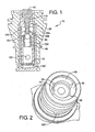
- FIG. 1 is a cross-sectional view of a valve assembly according to an embodiment of the invention
- FIG. 1A is a cross-sectional view of a valve assembly according to another embodiment of the invention.
- FIG. 2 is a bottom end perspective view of a portion of a valve assembly according to an embodiment of the invention
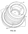
- FIG. 2A is a bottom end perspective view of a portion of a valve assembly according to another embodiment of the invention.
- FIG. 3 is a cross-sectional perspective view of a portion of a valve assembly according to another embodiment of the invention.
- FIG. 3A is a cross-sectional perspective view of a portion of a valve assembly according to another embodiment of the invention.
- FIG. 4 is a side perspective view of an insert according to an embodiment of the invention.
- FIG. 4A is a side perspective view of an insert according to another embodiment of the invention.
- FIG. 1 A cross-section of a pressure control valve assembly 10 according to an embodiment of the invention is illustrated in FIG. 1 .
- the valve assembly 10 may, for instance, be employed in connection with a hydraulic solenoid.
- the valve assembly 10 includes a valve body 20 that is configured to form an internal valving chamber (or cavity), an insert 30, a member 40, a ball 50, a plastic internal ball guide 60, and a plug 70.
- the valving chamber may be configured to retain and fully surround or encapsulate insert 30.
- Member 40 which may comprise a rod or poppet, may be configured to extend within a portion of insert 30 and maybe movable with respect to an exhaust port. Further, member 40 may be configured to move a ball 50 with respect to a flow port. While not illustrated, in other embodiments, member 40 and ball 50 may be formed integrally as a unitary component.
- the term "ball” is meant to also include components that may not necessarily be completely round, but rather may additionally include a component with a curved or spherical surface that is configured to communicate with a port in the assembly to restrict fluid flow.
- Embodiments of exhaust and flow ports are illustrated in connection with FIGS. 3 and 4 and are further discussed below. Further, if desired, several metering edges 90a, 90b, such as those identified in the embodiment illustrated in FIG. 1 , may be included.
- FIG. 1A Another embodiment of a valve assembly is generally illustrated in FIG. 1A .
- plastic material may completely cover the internal wall of the supply port (as opposed to other embodiments which might include two small ball guides).
- plastic may be allowed to flow from the outside of the insert to the inside of the insert around the perimeter of the supply port as well as through a plastic flow port (if a plastic flow port is provided).
- Insert 30 may be comprised of one or more metals. In an embodiment, insert 30 may be comprised of brass. Also, at least a portion of the valve body 20 and plastic internal ball guide 60 may be comprised of plastic. In an embodiment, the plastic internal ball guide 60 and at least a portion of the valve body 20 that is proximate the ball guide 60 about a flow port may be formed in the same molding operation and may be comprised of the same plastic material.
- the plastic material may include, by way of example and without limitation, a nylon or glass-filled nylon. However, the invention is not limited to the specific metal and plastic materials disclosed above, and other metal and plastic materials that are suitable for the intended operational environment may instead be used.
- Assembly 10 may further include one or more channel-forming members 80 positioned outside of insert 30 so as to permit fluid flow about insert 30.
- channel-forming members 80 are positioned about insert 30 and form two control pressure communication channels 82.
- the channel-forming members 80 may extend from a point about or below the lowermost portion of the insert 30 up to a point about or beyond an upper portion of control port 140.
- channel-forming members 82 are shown to extend from about a position below plug 70 to a position above control port 140.
- the invention is not limited to the illustrated configuration and may include less or more fingers 80 and/or communication channels 82, as may be necessary or desired for a given assembly or application.
- FIG. 2A generally illustrates another embodiment of bottom end of a portion of a valve assembly according to another embodiment of the invention.
- insert 30 associated with assembly 10 includes a supply pressure port or supply port 100.
- the general locations identified by lead lines 110 and 120 indicate respective positions where an exhaust port and plastic flow port (both not shown in the instant view) may be positioned in an embodiment of the invention.
- the invention is neither limited to one having a separate plastic flow port, nor one having such ports in the locations as depicted.
- such ports may be provided in positions other than those designated by lines 110 and 120 provided that the intended functions are adequately served.
- FIG. 3 generally illustrates a cross-sectional perspective view of a portion of a valve assembly according to an embodiment of the invention.
- ball 50 may be configured for operational registry or communication with plastic internal ball guide 60.
- a configuration of the assembly such as that disclosed can provide a centering feature for shut-off on a control end of.
- Further plug 70 may include a raised portion (generally identified as element 72) that extends further upwardly into a portion of insert 30.
- FIG. 3A generally illustrates another embodiment of the invention more of the type generally shown and described in connection with FIG. 1A .
- Insert 30 may include an exhaust port 130, a control port 140, a plastic flow port 150, a supply port 100, and a plug receiving portion or end (e.g., illustrated recessed plug seat 160).
- plastic internal ball guide 60 may be comprised of plastic and, further if desired, be formed or molded in the same operation as at least portions of the valve body 20 that are external to insert 30 and adjacent the plastic flow port 150.
- a plastic flow port 150 may be located at or about the center longitudinal length of insert 30 or at about the center longitudinal position of the plastic internal ball guide 60.
- a plurality of plastic flow ports 150 may be included and configured to enhance internal material distribution associated with a molding operation relative to the formation of internal ball guide 60.
- the geometry of insert 30 can be simplified for easier machining.
- FIG. 4A Another embodiment of an insert is shown in FIG. 4A .
- the illustrated insert 30 is similar to that depicted in FIG. 4 but includes two diameter-reduction transition portions that are generally identified as 170 and 172.
- the transition portions may include a ramp or inclined portion or segment 174, 176 between adjacent portions of the insert 30 connected by respective portions or segments 174, 176.
- the invention is not necessarily limited to an insert that includes a separate plastic flow port. That is, if desired for some configurations, one or more of the other "operational" ports associated with the assembly (e.g., pressure control port or supply port) may be utilized as a plastic "flow port" for purposes of forming all or a portion of an internal plastic component within the insert.
- a supply port or ports
- a supply port could be used as flow ports for forming all or a portion of a plastic internal ball guide within the insert and then subsequently serve its normal or intended role as a supply port for the assembly.
- insert 30 may include a plurality of one or more of the aforementioned ports. That is, provided the desired operational functions and characteristics are sufficiently met, insert 30 may be configured to include a plurality of exhaust ports, control ports, plastic flow ports (which may be optional for some embodiments), and/or supply ports. For example, as generally illustrated in FIGS. 3 and 4 , insert 30 may include two supply ports and two plastic flow ports, respectively. For instance, such "paired" combinations may be positioned approximately 180° relative to one another about the periphery of insert 30.
- an exhaust port 130, a flow port 150 and a supply port 100 may be generally aligned along the length of insert 30, while a pressure control port 140 may be generally offset by 90° (about the periphery of insert 30) relative to foregoing ports.
- a pressure control port 140 may be generally offset by 90° (about the periphery of insert 30) relative to foregoing ports.
- the individual shapes, sizes and comparative sizes of the various ports can be configured and modified without departing from the scope of the present invention.
- an assembly according to the invention can be provided. For instance, some embodiments allow for the manufacture of a relatively inexpensive device and a method for porting of pressures in the valve assembly in which a supply pressure may be applied to the side of the valve assembly and a control pressure can be in communication with the end of the valve assembly. Such configurations may additionally provide a centering feature for a shut-off valve on the control end of the valve assembly, while employing a robust plug (e.g., a steel plug) as a barrier between the control and supply communication ports 140,100.
- a robust plug e.g., a steel plug
- the present invention further discloses novel methods for making a valve body for a pressure control valve assembly.
- the present invention discloses a method for making a valve body in which several plastic portions, which may comprise the same or similar plastic materials, can be formed at the same time in connection with a single molding operation.
- a metal insert with at least one port for permitting the flow of a plastic material and a plug-receiving end is provided.
- a mold core is also provided and a portion of the core is positioned within a portion of the insert.
- a portion of the core is inserted into the insert through the plug-receiving end of the insert.
- the insert may then be fully or partially enclosed within a mold cavity.
- Additional mold forming components, as necessary to form the desired assembly components e.g., plastic channel-forming members that are intended to be positioned about the insert
- Plastic can then be molded about an outer surface of the insert such that a portion of the plastic being molded is permitted to flow about the insert and into the internal portion of the insert (where the plastic guide is intended) through a port associated with the insert.
- the port through which the plastic flows into the insert to form an internal plastic portion will be one or more separate plastic flow ports.
- one or more of the assembly's operational ports may be utilized as a plastic flow port for purposes of molding an internal component associated with the insert.
- At least a portion of the plastic that flows through the aforementioned port or ports forms all, or at least a portion, of a plastic internal ball guide within a portion of the insert.
- the core and/or other associated mold-formation components
- the core, as well as any associated mold formation components that are employed to form the plastic internal ball guide and the valve body about the insert, may be removed.
- Embodiments of the foregoing method can permit the molding associated with the insert to take place (both internally and externally with respect to the insert) in connection with the same molding step or operation, and at or substantially at the same time.
- final formation times associated with the various components may vary.
- the same plastic material can form portions of both the internal ball guide and the external valve body.
- the metal insert may include one or more exhaust ports, pressure control ports, and/or supply ports.
- the process may, for example, include injection molding and/or compression molding.
Landscapes
- Engineering & Computer Science (AREA)
- Physics & Mathematics (AREA)
- General Engineering & Computer Science (AREA)
- Fluid Mechanics (AREA)
- Mechanical Engineering (AREA)
- General Physics & Mathematics (AREA)
- Automation & Control Theory (AREA)
- Valve Housings (AREA)
- Lift Valve (AREA)
- Taps Or Cocks (AREA)
Claims (22)
- Drucksteuerventilanordnung (10), gekennzeichnet durch:einen Ventilkörper (20), der einen Ventilhohlraum enthält, wobei wenigstens ein Teil des Ventilkörpers (20) aus Kunststoff hergestellt ist;einen Metalleinsatz (30), der innerhalb des Ventilhohlraums fixiert ist; wobei der Einsatz (30) eine Austrittsöffrung (130), eine Drucksteueröffnung (140), eine Zuführöffnung (100) und ein Stopfenaufnahmeende enthält;ein Element (40), das sich innerhalb eines Abschnitts des Einsatzes (30) erstreckt und in Bezug auf die Austrittsöffnung (130) bewegbar ist, wobei das Element (40) eine Kugel (50) in Bezug auf eine Zuführöffnung (100) bewegt; undeine innere Kugelführung (60), die innerhalb eines Abschnitts des Einsatzes (30) enthalten ist, wobei die innere Kugelführung (60) aus dem gleichen Kunststoff wie der Teil des ventilkörpers (20) ausgebildet ist.
- Ventilanordnung (10) nach Anspruch 1, die einen in dem Stopfenaufnahmeende des Einsatzes (30) aufgenommenen Stopfen (70) enthält.
- Ventilanordnung (10) nach Anspruch 2, wobei der Stopfen (70) aus Stahl besteht.
- Ventilanordnung (10) nach Anspruch 1, die eine Kunststoffdurchflussöffnung (150) enthält.
- Ventilanordnung (10) nach Anspruch 1, wobei das Stopfenende einen Stopfensitz (160) enthält.
- Ventilanordnung (10) nach Anspruch 1, wobei der Ventilkörper (20) ein Kunststoffmaterial aufweist.
- Ventilanordnung (10) nach Anspruch 6, wobei das Kunststoffmaterial glasfaserverstärktes Nylon aufweiset.
- Ventilanordnung (10) nach Anspruch 6, wobei die innere Kugelführung (60) aus Kunststoff und der Ventilkörper (20) dasselbe Kunststoffmaterial enthalten.
- Ventilanordnung (10) nach Anspruch 1, wobei der Metallleitsatz (30) Messing aufweist.
- Ventilanordnung (10) nach Anspruch 1, wobei das Element (40) Stahl aufweist.
- Ventilanordnung (10) nach Anspruch 1, wobei die Kugel (50) Stahl aufweist.
- Ventilanordnung (10) nach Anspruch 1, wobei das Element (40) einen Stab oder ein Sitzventil aufweist.
- Ventilanordnung (10) nach Anspruch 1, die wenigstens ein Element (72) enthält, das sich entlang einer äußeren Oberfläche des Metalleinsatzes (30) zwischen dem Stopfenaufnahmeende und der Drucksteueröffnung (140) erstreckt, um die Strömung eines Fluids an dem Metalleinsatz (30) vorbei zuzulassen.
- Verfahren zur Herstellung eines Ventilkörpers (20) für eine Ventilanordnung (10), gekennzeichnet durch:Bereitstellen eines Metalleinsatzes (30), der eine Öffnung zur Zulassung des Durchflusses eines Kunststoffmaterials und ein Stopfenaufnahmeende enthält;Bereitstellen eines Formkerns;Positionieren des Formkerns innerhalb eines Abschnitts des Metalleinsatzes (30);Umschließen des Einsatzes (30) innerhalb eines Formhohlraums;Formen von Kunststoff um eine Außenfläche des Metalleinsatzes (30) herum, um den Metalleinsatz (30) innerhalb des Ventilkörpers (20) zu fixieren, und Formen von Kunststoff durch die Öffnung (150) des Metalleinsatzes (30) hindurch, um wenigstens einen Abschnitt einer inneren Kugelführung (60) aus Kunststoff innerhalb eines inneren Abschnitts des Metalleinsatzes (30) zu formen; undEntfernen des Formkerns.
- Verfahren nach Anspruch 14, wobei der Metalleinsatz (30) eine Austrittsöffnung (130), eine Drucksteueröffnung (140) und eine Zuführöffnung (100) enthält.
- Verfahren nach Anspruch 15, wobei die Öffnung (150) zur Zulassung des Durchflusses eines Kunststoffmaterials zusätzlich zu der Austrittsöffnung (130), der Drucksteueröffnung (140) und der Zuführöffnung (100) vorhanden ist.
- Verfahren nach Anspruch 15, wobei die Öffnung (150) zur Zulassung des Durchflusses eines Kunststoffmaterials wenigstens eine von der Austrittsöffnung (130), der Drucksteueröffnung (140) und der Zuführöffnung (100) ist.
- Verfahren nach Anspruch 14, wobei das Formen Spritzgießen oder Formpressen enthält.
- Verfahren nach Anspruch 14, wobei das Formen von Kunststoff um die Außenfläche des Einsatzes (30) herum und das Formen der inneren Kugelführung (60) innerhalb eines Abschnitts des Einsatzes (30) in Verbindung mit einem einzigen Formungsschritt oder -vorgang erfolgt.
- Verfahren nach Anspruch 19, wobei das Formen von Kunststoff um die Außenfläche des Einsatzes (30) herum und das Formen der inneren Kugelführung (60) innerhalb eines Abschnitts des Einsatzes (30) gleichzeitig oder im Wesentlichen gleichzeitig erfolgt.
- Verfahren nach Anspruch 14, wobei der Formkern mehrere Formkernkomponenten aufweist.
- Verfahren nach Anspruch 14, wobei ein oder mehrere kanalbildende Elemente (80, 82) um den Metalleinsatz herum gebildet werden.
Priority Applications (1)
| Application Number | Priority Date | Filing Date | Title |
|---|---|---|---|
| PL08719292T PL2118715T3 (pl) | 2007-03-13 | 2008-03-13 | Zespół zaworu sterującego ciśnieniem |
Applications Claiming Priority (2)
| Application Number | Priority Date | Filing Date | Title |
|---|---|---|---|
| US11/685,578 US7766040B2 (en) | 2007-03-13 | 2007-03-13 | Pressure control valve assembly |
| PCT/IB2008/000585 WO2008110904A2 (en) | 2007-03-13 | 2008-03-13 | Pressure control valve assembly |
Publications (2)
| Publication Number | Publication Date |
|---|---|
| EP2118715A2 EP2118715A2 (de) | 2009-11-18 |
| EP2118715B1 true EP2118715B1 (de) | 2013-04-17 |
Family
ID=39712181
Family Applications (1)
| Application Number | Title | Priority Date | Filing Date |
|---|---|---|---|
| EP20080719292 Not-in-force EP2118715B1 (de) | 2007-03-13 | 2008-03-13 | Druckregelventilanordnung |
Country Status (9)
| Country | Link |
|---|---|
| US (2) | US7766040B2 (de) |
| EP (1) | EP2118715B1 (de) |
| JP (1) | JP5387910B2 (de) |
| KR (1) | KR20090119973A (de) |
| CN (1) | CN101796464B (de) |
| AU (1) | AU2008224619B2 (de) |
| MX (1) | MX2009009828A (de) |
| PL (1) | PL2118715T3 (de) |
| WO (1) | WO2008110904A2 (de) |
Families Citing this family (12)
| Publication number | Priority date | Publication date | Assignee | Title |
|---|---|---|---|---|
| JP2008045486A (ja) * | 2006-08-16 | 2008-02-28 | Yanmar Co Ltd | 蓄圧式燃料噴射装置 |
| DE102007035472A1 (de) * | 2007-07-26 | 2009-01-29 | Svm Schultz Verwaltungs-Gmbh & Co. Kg | Ventil |
| CN102007331B (zh) | 2008-04-28 | 2014-11-05 | 博格华纳公司 | 用于螺线管的液压路径安排的包覆模制或压入式套管 |
| WO2010071151A1 (ja) * | 2008-12-18 | 2010-06-24 | アイシン精機株式会社 | オイルコントロールバルブ取付構造 |
| US20100280707A1 (en) * | 2009-04-30 | 2010-11-04 | Searete Llc, A Limited Liability Corporation Of State Of Delaware | Awarding standings to a vehicle based upon one or more fuel utilization characteristics |
| US8746279B2 (en) * | 2011-09-14 | 2014-06-10 | Delphi Technologies, Inc. | Pressure control valve |
| EP2592519B1 (de) * | 2011-11-12 | 2014-04-30 | FESTO AG & Co. KG | Druckregeleinrichtung sowie Verfahren zum Betreiben einer Druckregeleinrichtung |
| GB201122011D0 (en) * | 2011-12-21 | 2012-02-01 | Haldex Brake Products Ltd | Valve assembly |
| DE102012104456B3 (de) * | 2012-05-23 | 2013-05-29 | Pierburg Gmbh | Ventilvorrichtung für einen Hydraulikkreislauf sowie Ölpumpenregelanordnung |
| US9201049B2 (en) * | 2013-03-13 | 2015-12-01 | Idex Health & Science Llc | Connector with structural reinforcement and biocompatible fluid passageway |
| JP7173837B2 (ja) * | 2018-11-06 | 2022-11-16 | 株式会社鷺宮製作所 | 温度式膨張弁 |
| DE102020109767A1 (de) * | 2020-04-08 | 2021-10-14 | Grohe Ag | Anschlusskörper für einen Unterputzeinbaukörper |
Family Cites Families (33)
| Publication number | Priority date | Publication date | Assignee | Title |
|---|---|---|---|---|
| DE1207603B (de) * | 1961-02-11 | 1965-12-23 | Friedrich Stuebbe | Verfahren zum Herstellen von Kuekenhaehnen |
| US3580286A (en) * | 1969-04-04 | 1971-05-25 | Stewart Warner Corp | Spool valve |
| US3698687A (en) * | 1970-07-17 | 1972-10-17 | Ktm Ind Inc | Rotatory valve having one-piece seat construction |
| FR2178464A5 (de) * | 1972-03-31 | 1973-11-09 | Peugeot & Renault | |
| US3807692A (en) * | 1972-05-01 | 1974-04-30 | Dynatech Corp | Valve, method of manufacture of valve and valve made by such method |
| US3894712A (en) * | 1973-07-06 | 1975-07-15 | Parker Hannifin Corp | Excess flow servo valve |
| US4180542A (en) * | 1973-09-04 | 1979-12-25 | Celanese Corporation | Methods for making molded plug and plug valve |
| US3961770A (en) * | 1973-09-04 | 1976-06-08 | Celanese Corporation | Plug valve |
| US4172583A (en) * | 1975-11-25 | 1979-10-30 | Wrasman Thomas J | Molded valve |
| DE2705914C2 (de) * | 1977-02-09 | 1982-06-16 | Siemens AG, 1000 Berlin und 8000 München | Umsteuerventil |
| US4488573A (en) * | 1981-10-23 | 1984-12-18 | Nibco Inc. | Apparatus for preventing thermal damage to a preformed plug during molding of a housing therearound |
| US4430285A (en) * | 1981-10-23 | 1984-02-07 | Nibco Inc. | Method and apparatus for preventing thermal damage to a preformed plug during molding of a housing therearound |
| EP0103349A1 (de) * | 1982-08-12 | 1984-03-21 | General Motors Corporation | Variables Druckregelventil |
| US4516594A (en) * | 1984-04-03 | 1985-05-14 | Diesel Equipment Limited | Multi-part valve with a valve seat skeleton and cast valve body |
| DE4317786C1 (de) * | 1993-05-28 | 1994-11-10 | Luk Fahrzeug Hydraulik | Ventilanordnung |
| DE4317881C2 (de) * | 1993-05-28 | 1997-02-06 | Luk Fahrzeug Hydraulik | Ventilanordnung |
| JP3219611B2 (ja) * | 1994-10-04 | 2001-10-15 | 三菱電機株式会社 | 三方電磁弁及びその組立方法 |
| JP3370210B2 (ja) * | 1995-06-22 | 2003-01-27 | 三菱エンジニアリングプラスチックス株式会社 | 合成樹脂製流体制御バルブ本体 |
| US6041807A (en) * | 1997-04-09 | 2000-03-28 | Toyoda Koki Kabushiki Kaisha | Flow control device of power steering apparatus |
| US5894860A (en) * | 1997-06-12 | 1999-04-20 | General Motors Corporation | Proportional pressure control solenoid valve |
| JP3471568B2 (ja) * | 1997-06-18 | 2003-12-02 | 三菱電機株式会社 | 三方電磁弁 |
| DE50012876D1 (de) * | 1999-02-22 | 2006-07-20 | Hydraulik Ring Gmbh | Wegesitzventil |
| US6260820B1 (en) * | 1999-05-21 | 2001-07-17 | Nordstrom Valves, Inc. | Valve with rotatable valve member and method for forming same |
| CN2407199Y (zh) * | 2000-01-14 | 2000-11-22 | 成都仪表阀门二厂 | 改进的流体压力调节装置 |
| US20030136449A1 (en) | 2002-01-18 | 2003-07-24 | Eaton Corporation | Solenoid operated variable bleed pressure control valve with integral shutoff feature |
| DE10226594A1 (de) * | 2002-06-14 | 2004-01-08 | Robert Bosch Gmbh | Regelklappe mit eingespritzter Welle |
| US6810909B2 (en) | 2002-08-08 | 2004-11-02 | Eaton Corporation | Solenoid operated pressure control valve |
| JP2004332855A (ja) * | 2003-05-09 | 2004-11-25 | Fuji Koki Corp | 電動弁 |
| JP4515075B2 (ja) * | 2003-11-07 | 2010-07-28 | 株式会社デンソー | 内燃機関用スロットル装置の射出成形方法 |
| JP2005233395A (ja) * | 2004-02-23 | 2005-09-02 | Onda Seisakusho Seki Kojo:Kk | ボールバルブ |
| WO2005116423A1 (ja) * | 2004-05-31 | 2005-12-08 | Aisan Kogyo Kabushiki Kaisha | スロットルボデーの成形方法及びスロットルボデー |
| CN2786391Y (zh) * | 2004-12-17 | 2006-06-07 | 上海华岛液压设备制造有限公司 | 先导式溢流阀 |
| JP4933082B2 (ja) * | 2005-11-04 | 2012-05-16 | 愛三工業株式会社 | バタフライ弁 |
-
2007
- 2007-03-13 US US11/685,578 patent/US7766040B2/en not_active Expired - Fee Related
-
2008
- 2008-03-13 WO PCT/IB2008/000585 patent/WO2008110904A2/en not_active Ceased
- 2008-03-13 CN CN2008800080687A patent/CN101796464B/zh not_active Expired - Fee Related
- 2008-03-13 EP EP20080719292 patent/EP2118715B1/de not_active Not-in-force
- 2008-03-13 PL PL08719292T patent/PL2118715T3/pl unknown
- 2008-03-13 JP JP2009553230A patent/JP5387910B2/ja not_active Expired - Fee Related
- 2008-03-13 AU AU2008224619A patent/AU2008224619B2/en not_active Ceased
- 2008-03-13 MX MX2009009828A patent/MX2009009828A/es active IP Right Grant
- 2008-03-13 KR KR1020097018986A patent/KR20090119973A/ko not_active Ceased
-
2010
- 2010-07-06 US US12/830,693 patent/US8231818B2/en not_active Expired - Fee Related
Also Published As
| Publication number | Publication date |
|---|---|
| WO2008110904A3 (en) | 2009-12-23 |
| JP2010521627A (ja) | 2010-06-24 |
| US7766040B2 (en) | 2010-08-03 |
| PL2118715T3 (pl) | 2013-09-30 |
| CN101796464A (zh) | 2010-08-04 |
| CN101796464B (zh) | 2012-08-29 |
| MX2009009828A (es) | 2009-09-24 |
| JP5387910B2 (ja) | 2014-01-15 |
| US20100270703A1 (en) | 2010-10-28 |
| EP2118715A2 (de) | 2009-11-18 |
| US20080224084A1 (en) | 2008-09-18 |
| WO2008110904A2 (en) | 2008-09-18 |
| AU2008224619A1 (en) | 2008-09-18 |
| KR20090119973A (ko) | 2009-11-23 |
| US8231818B2 (en) | 2012-07-31 |
| AU2008224619B2 (en) | 2013-09-12 |
Similar Documents
| Publication | Publication Date | Title |
|---|---|---|
| EP2118715B1 (de) | Druckregelventilanordnung | |
| TWI707101B (zh) | 流體控制閥 | |
| US4082116A (en) | Electromagnetic two-way valve | |
| TWI242627B (en) | Slide spool valve | |
| CN103438238B (zh) | 三通式液控单向阀 | |
| WO2005026591A3 (en) | Fluid jet for providing fluid under pressure to a desired location | |
| CN220185962U (zh) | 排水阀 | |
| CN108005983A (zh) | 一种大流量电磁球阀 | |
| CA2122501C (en) | Balanced, steam control valve assembly, and a plug-type valving element therefor | |
| CN105221756B (zh) | 稳定型截止阀 | |
| US8186370B2 (en) | Solenoid plunger core seal | |
| CN107676514B (zh) | 一种全海深超高压海水调速阀 | |
| US5005538A (en) | Extended circumference intake poppet valve system for opening and sealing a single valve seat | |
| KR100512423B1 (ko) | 유압제어용 스풀밸브 | |
| CN210687191U (zh) | 一种排气阀驱动机构及排气阀 | |
| JPH11257509A (ja) | 方向制御弁 | |
| CN208951656U (zh) | 一种用于机油控制阀的阀套 | |
| CN202182240U (zh) | 电磁阀 | |
| CN216242417U (zh) | 一种双阀芯平衡笼式调节阀 | |
| CN204852462U (zh) | 气动换向阀 | |
| CN214533778U (zh) | 一种螺纹插装式平衡阀 | |
| JPH026305Y2 (de) | ||
| CN205244491U (zh) | 六通阀门 | |
| CN207716060U (zh) | 一种集中润滑系统液体定量分配器 | |
| CN101054942A (zh) | 内燃机的燃料喷射器 |
Legal Events
| Date | Code | Title | Description |
|---|---|---|---|
| PUAI | Public reference made under article 153(3) epc to a published international application that has entered the european phase |
Free format text: ORIGINAL CODE: 0009012 |
|
| 17P | Request for examination filed |
Effective date: 20090825 |
|
| AK | Designated contracting states |
Kind code of ref document: A2 Designated state(s): AT BE BG CH CY CZ DE DK EE ES FI FR GB GR HR HU IE IS IT LI LT LU LV MC MT NL NO PL PT RO SE SI SK TR |
|
| R17D | Deferred search report published (corrected) |
Effective date: 20091223 |
|
| DAX | Request for extension of the european patent (deleted) | ||
| 17Q | First examination report despatched |
Effective date: 20110215 |
|
| REG | Reference to a national code |
Ref country code: DE Ref legal event code: R079 Ref document number: 602008023882 Country of ref document: DE Free format text: PREVIOUS MAIN CLASS: G05D0016100000 Ipc: F16K0017020000 |
|
| RIC1 | Information provided on ipc code assigned before grant |
Ipc: F16K 17/02 20060101AFI20120525BHEP Ipc: G05D 16/20 20060101ALI20120525BHEP Ipc: G05D 16/10 20060101ALI20120525BHEP |
|
| GRAP | Despatch of communication of intention to grant a patent |
Free format text: ORIGINAL CODE: EPIDOSNIGR1 |
|
| GRAS | Grant fee paid |
Free format text: ORIGINAL CODE: EPIDOSNIGR3 |
|
| GRAA | (expected) grant |
Free format text: ORIGINAL CODE: 0009210 |
|
| AK | Designated contracting states |
Kind code of ref document: B1 Designated state(s): AT BE BG CH CY CZ DE DK EE ES FI FR GB GR HR HU IE IS IT LI LT LU LV MC MT NL NO PL PT RO SE SI SK TR |
|
| REG | Reference to a national code |
Ref country code: GB Ref legal event code: FG4D |
|
| REG | Reference to a national code |
Ref country code: CH Ref legal event code: EP |
|
| REG | Reference to a national code |
Ref country code: IE Ref legal event code: FG4D |
|
| REG | Reference to a national code |
Ref country code: AT Ref legal event code: REF Ref document number: 607520 Country of ref document: AT Kind code of ref document: T Effective date: 20130515 |
|
| REG | Reference to a national code |
Ref country code: SE Ref legal event code: TRGR |
|
| REG | Reference to a national code |
Ref country code: DE Ref legal event code: R096 Ref document number: 602008023882 Country of ref document: DE Effective date: 20130613 |
|
| REG | Reference to a national code |
Ref country code: AT Ref legal event code: MK05 Ref document number: 607520 Country of ref document: AT Kind code of ref document: T Effective date: 20130417 |
|
| REG | Reference to a national code |
Ref country code: LT Ref legal event code: MG4D |
|
| REG | Reference to a national code |
Ref country code: PL Ref legal event code: T3 |
|
| REG | Reference to a national code |
Ref country code: NL Ref legal event code: VDEP Effective date: 20130417 |
|
| PG25 | Lapsed in a contracting state [announced via postgrant information from national office to epo] |
Ref country code: LT Free format text: LAPSE BECAUSE OF FAILURE TO SUBMIT A TRANSLATION OF THE DESCRIPTION OR TO PAY THE FEE WITHIN THE PRESCRIBED TIME-LIMIT Effective date: 20130417 Ref country code: FI Free format text: LAPSE BECAUSE OF FAILURE TO SUBMIT A TRANSLATION OF THE DESCRIPTION OR TO PAY THE FEE WITHIN THE PRESCRIBED TIME-LIMIT Effective date: 20130417 Ref country code: BE Free format text: LAPSE BECAUSE OF FAILURE TO SUBMIT A TRANSLATION OF THE DESCRIPTION OR TO PAY THE FEE WITHIN THE PRESCRIBED TIME-LIMIT Effective date: 20130417 Ref country code: SI Free format text: LAPSE BECAUSE OF FAILURE TO SUBMIT A TRANSLATION OF THE DESCRIPTION OR TO PAY THE FEE WITHIN THE PRESCRIBED TIME-LIMIT Effective date: 20130417 Ref country code: GR Free format text: LAPSE BECAUSE OF FAILURE TO SUBMIT A TRANSLATION OF THE DESCRIPTION OR TO PAY THE FEE WITHIN THE PRESCRIBED TIME-LIMIT Effective date: 20130718 Ref country code: PT Free format text: LAPSE BECAUSE OF FAILURE TO SUBMIT A TRANSLATION OF THE DESCRIPTION OR TO PAY THE FEE WITHIN THE PRESCRIBED TIME-LIMIT Effective date: 20130819 Ref country code: NO Free format text: LAPSE BECAUSE OF FAILURE TO SUBMIT A TRANSLATION OF THE DESCRIPTION OR TO PAY THE FEE WITHIN THE PRESCRIBED TIME-LIMIT Effective date: 20130717 Ref country code: ES Free format text: LAPSE BECAUSE OF FAILURE TO SUBMIT A TRANSLATION OF THE DESCRIPTION OR TO PAY THE FEE WITHIN THE PRESCRIBED TIME-LIMIT Effective date: 20130728 Ref country code: AT Free format text: LAPSE BECAUSE OF FAILURE TO SUBMIT A TRANSLATION OF THE DESCRIPTION OR TO PAY THE FEE WITHIN THE PRESCRIBED TIME-LIMIT Effective date: 20130417 Ref country code: IS Free format text: LAPSE BECAUSE OF FAILURE TO SUBMIT A TRANSLATION OF THE DESCRIPTION OR TO PAY THE FEE WITHIN THE PRESCRIBED TIME-LIMIT Effective date: 20130817 |
|
| PG25 | Lapsed in a contracting state [announced via postgrant information from national office to epo] |
Ref country code: HR Free format text: LAPSE BECAUSE OF FAILURE TO SUBMIT A TRANSLATION OF THE DESCRIPTION OR TO PAY THE FEE WITHIN THE PRESCRIBED TIME-LIMIT Effective date: 20130417 Ref country code: BG Free format text: LAPSE BECAUSE OF FAILURE TO SUBMIT A TRANSLATION OF THE DESCRIPTION OR TO PAY THE FEE WITHIN THE PRESCRIBED TIME-LIMIT Effective date: 20130717 Ref country code: CY Free format text: LAPSE BECAUSE OF FAILURE TO SUBMIT A TRANSLATION OF THE DESCRIPTION OR TO PAY THE FEE WITHIN THE PRESCRIBED TIME-LIMIT Effective date: 20130417 Ref country code: LV Free format text: LAPSE BECAUSE OF FAILURE TO SUBMIT A TRANSLATION OF THE DESCRIPTION OR TO PAY THE FEE WITHIN THE PRESCRIBED TIME-LIMIT Effective date: 20130417 |
|
| PG25 | Lapsed in a contracting state [announced via postgrant information from national office to epo] |
Ref country code: DK Free format text: LAPSE BECAUSE OF FAILURE TO SUBMIT A TRANSLATION OF THE DESCRIPTION OR TO PAY THE FEE WITHIN THE PRESCRIBED TIME-LIMIT Effective date: 20130417 Ref country code: EE Free format text: LAPSE BECAUSE OF FAILURE TO SUBMIT A TRANSLATION OF THE DESCRIPTION OR TO PAY THE FEE WITHIN THE PRESCRIBED TIME-LIMIT Effective date: 20130417 Ref country code: CZ Free format text: LAPSE BECAUSE OF FAILURE TO SUBMIT A TRANSLATION OF THE DESCRIPTION OR TO PAY THE FEE WITHIN THE PRESCRIBED TIME-LIMIT Effective date: 20130417 Ref country code: SK Free format text: LAPSE BECAUSE OF FAILURE TO SUBMIT A TRANSLATION OF THE DESCRIPTION OR TO PAY THE FEE WITHIN THE PRESCRIBED TIME-LIMIT Effective date: 20130417 |
|
| PLBE | No opposition filed within time limit |
Free format text: ORIGINAL CODE: 0009261 |
|
| STAA | Information on the status of an ep patent application or granted ep patent |
Free format text: STATUS: NO OPPOSITION FILED WITHIN TIME LIMIT |
|
| PG25 | Lapsed in a contracting state [announced via postgrant information from national office to epo] |
Ref country code: NL Free format text: LAPSE BECAUSE OF FAILURE TO SUBMIT A TRANSLATION OF THE DESCRIPTION OR TO PAY THE FEE WITHIN THE PRESCRIBED TIME-LIMIT Effective date: 20130417 Ref country code: RO Free format text: LAPSE BECAUSE OF FAILURE TO SUBMIT A TRANSLATION OF THE DESCRIPTION OR TO PAY THE FEE WITHIN THE PRESCRIBED TIME-LIMIT Effective date: 20130417 |
|
| 26N | No opposition filed |
Effective date: 20140120 |
|
| REG | Reference to a national code |
Ref country code: DE Ref legal event code: R097 Ref document number: 602008023882 Country of ref document: DE Effective date: 20140120 |
|
| PG25 | Lapsed in a contracting state [announced via postgrant information from national office to epo] |
Ref country code: LU Free format text: LAPSE BECAUSE OF FAILURE TO SUBMIT A TRANSLATION OF THE DESCRIPTION OR TO PAY THE FEE WITHIN THE PRESCRIBED TIME-LIMIT Effective date: 20140313 |
|
| REG | Reference to a national code |
Ref country code: CH Ref legal event code: PL |
|
| REG | Reference to a national code |
Ref country code: IE Ref legal event code: MM4A |
|
| PG25 | Lapsed in a contracting state [announced via postgrant information from national office to epo] |
Ref country code: CH Free format text: LAPSE BECAUSE OF NON-PAYMENT OF DUE FEES Effective date: 20140331 Ref country code: LI Free format text: LAPSE BECAUSE OF NON-PAYMENT OF DUE FEES Effective date: 20140331 Ref country code: IE Free format text: LAPSE BECAUSE OF NON-PAYMENT OF DUE FEES Effective date: 20140313 |
|
| REG | Reference to a national code |
Ref country code: FR Ref legal event code: PLFP Year of fee payment: 8 |
|
| PGFP | Annual fee paid to national office [announced via postgrant information from national office to epo] |
Ref country code: IT Payment date: 20150325 Year of fee payment: 8 |
|
| PGFP | Annual fee paid to national office [announced via postgrant information from national office to epo] |
Ref country code: FR Payment date: 20150224 Year of fee payment: 8 Ref country code: GB Payment date: 20150224 Year of fee payment: 8 Ref country code: PL Payment date: 20150223 Year of fee payment: 8 Ref country code: SE Payment date: 20150306 Year of fee payment: 8 |
|
| PGFP | Annual fee paid to national office [announced via postgrant information from national office to epo] |
Ref country code: DE Payment date: 20150331 Year of fee payment: 8 |
|
| PG25 | Lapsed in a contracting state [announced via postgrant information from national office to epo] |
Ref country code: MT Free format text: LAPSE BECAUSE OF FAILURE TO SUBMIT A TRANSLATION OF THE DESCRIPTION OR TO PAY THE FEE WITHIN THE PRESCRIBED TIME-LIMIT Effective date: 20130417 |
|
| PG25 | Lapsed in a contracting state [announced via postgrant information from national office to epo] |
Ref country code: MC Free format text: LAPSE BECAUSE OF FAILURE TO SUBMIT A TRANSLATION OF THE DESCRIPTION OR TO PAY THE FEE WITHIN THE PRESCRIBED TIME-LIMIT Effective date: 20130417 |
|
| PG25 | Lapsed in a contracting state [announced via postgrant information from national office to epo] |
Ref country code: TR Free format text: LAPSE BECAUSE OF FAILURE TO SUBMIT A TRANSLATION OF THE DESCRIPTION OR TO PAY THE FEE WITHIN THE PRESCRIBED TIME-LIMIT Effective date: 20130417 Ref country code: HU Free format text: LAPSE BECAUSE OF FAILURE TO SUBMIT A TRANSLATION OF THE DESCRIPTION OR TO PAY THE FEE WITHIN THE PRESCRIBED TIME-LIMIT; INVALID AB INITIO Effective date: 20080313 |
|
| REG | Reference to a national code |
Ref country code: DE Ref legal event code: R119 Ref document number: 602008023882 Country of ref document: DE |
|
| REG | Reference to a national code |
Ref country code: SE Ref legal event code: EUG |
|
| GBPC | Gb: european patent ceased through non-payment of renewal fee |
Effective date: 20160313 |
|
| PG25 | Lapsed in a contracting state [announced via postgrant information from national office to epo] |
Ref country code: SE Free format text: LAPSE BECAUSE OF NON-PAYMENT OF DUE FEES Effective date: 20160314 |
|
| REG | Reference to a national code |
Ref country code: FR Ref legal event code: ST Effective date: 20161130 |
|
| PG25 | Lapsed in a contracting state [announced via postgrant information from national office to epo] |
Ref country code: GB Free format text: LAPSE BECAUSE OF NON-PAYMENT OF DUE FEES Effective date: 20160313 Ref country code: DE Free format text: LAPSE BECAUSE OF NON-PAYMENT OF DUE FEES Effective date: 20161001 Ref country code: FR Free format text: LAPSE BECAUSE OF NON-PAYMENT OF DUE FEES Effective date: 20160331 |
|
| PG25 | Lapsed in a contracting state [announced via postgrant information from national office to epo] |
Ref country code: IT Free format text: LAPSE BECAUSE OF NON-PAYMENT OF DUE FEES Effective date: 20160313 |
|
| PG25 | Lapsed in a contracting state [announced via postgrant information from national office to epo] |
Ref country code: PL Free format text: LAPSE BECAUSE OF NON-PAYMENT OF DUE FEES Effective date: 20160313 |