EP2118509B1 - Elektromechanischer kupplungsaktuator - Google Patents
Elektromechanischer kupplungsaktuator Download PDFInfo
- Publication number
- EP2118509B1 EP2118509B1 EP08717154A EP08717154A EP2118509B1 EP 2118509 B1 EP2118509 B1 EP 2118509B1 EP 08717154 A EP08717154 A EP 08717154A EP 08717154 A EP08717154 A EP 08717154A EP 2118509 B1 EP2118509 B1 EP 2118509B1
- Authority
- EP
- European Patent Office
- Prior art keywords
- sleeve
- clutch actuator
- actuator according
- clutch
- sleeve element
- Prior art date
- Legal status (The legal status is an assumption and is not a legal conclusion. Google has not performed a legal analysis and makes no representation as to the accuracy of the status listed.)
- Not-in-force
Links
- 230000008878 coupling Effects 0.000 title abstract description 6
- 238000010168 coupling process Methods 0.000 title abstract description 6
- 238000005859 coupling reaction Methods 0.000 title abstract description 6
- 238000006073 displacement reaction Methods 0.000 claims abstract 2
- 230000003134 recirculating effect Effects 0.000 claims 1
- 230000005540 biological transmission Effects 0.000 abstract description 17
- 238000009434 installation Methods 0.000 description 2
- 238000006243 chemical reaction Methods 0.000 description 1
- 230000001419 dependent effect Effects 0.000 description 1
- 210000003746 feather Anatomy 0.000 description 1
- 125000006850 spacer group Chemical group 0.000 description 1
Images


Classifications
-
- F—MECHANICAL ENGINEERING; LIGHTING; HEATING; WEAPONS; BLASTING
- F16—ENGINEERING ELEMENTS AND UNITS; GENERAL MEASURES FOR PRODUCING AND MAINTAINING EFFECTIVE FUNCTIONING OF MACHINES OR INSTALLATIONS; THERMAL INSULATION IN GENERAL
- F16D—COUPLINGS FOR TRANSMITTING ROTATION; CLUTCHES; BRAKES
- F16D28/00—Electrically-actuated clutches
-
- F—MECHANICAL ENGINEERING; LIGHTING; HEATING; WEAPONS; BLASTING
- F16—ENGINEERING ELEMENTS AND UNITS; GENERAL MEASURES FOR PRODUCING AND MAINTAINING EFFECTIVE FUNCTIONING OF MACHINES OR INSTALLATIONS; THERMAL INSULATION IN GENERAL
- F16D—COUPLINGS FOR TRANSMITTING ROTATION; CLUTCHES; BRAKES
- F16D23/00—Details of mechanically-actuated clutches not specific for one distinct type
- F16D23/12—Mechanical clutch-actuating mechanisms arranged outside the clutch as such
-
- F—MECHANICAL ENGINEERING; LIGHTING; HEATING; WEAPONS; BLASTING
- F16—ENGINEERING ELEMENTS AND UNITS; GENERAL MEASURES FOR PRODUCING AND MAINTAINING EFFECTIVE FUNCTIONING OF MACHINES OR INSTALLATIONS; THERMAL INSULATION IN GENERAL
- F16D—COUPLINGS FOR TRANSMITTING ROTATION; CLUTCHES; BRAKES
- F16D23/00—Details of mechanically-actuated clutches not specific for one distinct type
- F16D23/12—Mechanical clutch-actuating mechanisms arranged outside the clutch as such
- F16D2023/123—Clutch actuation by cams, ramps or ball-screw mechanisms
Definitions
- the present invention relates to an electromechanical clutch actuator for actuating a clutch of an automated manual transmission of a vehicle according to the closer defined in the preamble of claim 1.
- a generic clutch actuator is off WO-A-03/087609 known.
- the clutch actuator includes an electric motor as a drive, which is coupled to a release mechanism.
- the disengagement mechanism includes a housing disposed coaxially with a transmission shaft and is supported on a gearbox-side bracket.
- the rotational movement of the electric motor is converted via a worm into an axial movement for actuating the release bearing of the clutch, wherein the worm is engaged with a toothing on the housing.
- the housing is supported on its inside on a coarse thread, so that the rotating housing is moved to actuate the release bearing in the axial direction.
- the known clutch actuators require a plurality of components for the release mechanism in order to operate the clutch in the desired manner.
- the known clutch actuators are expensive and require a considerable amount of space.
- the present invention seeks to propose an electromechanical clutch actuator of the type described above, which is as simple as possible and has a low space requirement.
- the clutch actuator should allow the adjustment of possible installation tolerances between the clutch and the transmission
- an electromechanical clutch actuator is proposed on a transmission shaft for actuating a clutch of an automated transmission or the like of a vehicle.
- the clutch actuator according to the invention comprises as drive an electric motor and a rotational movement of the electric motor in an axial movement of the clutch release bearing of the clutch conversion mechanism, which is arranged coaxially with the transmission shaft in the manner of an electromechanical Gottausschreibers, wherein the disengaging mechanism comprises a rotary housing, on which a first sleeve member is arranged, which is in the axial direction with a second, corresponding sleeve member for axially displacing the release bearing in operative connection, wherein on the second sleeve member coupling side an intermediate sleeve is arranged, which rests overlapping in an inner diameter stage of the second sleeve member.
- the rotary housing with the first sleeve member is rotatably mounted on an outer housing or the like.
- rotational movements of the first sleeve member are possible without causing an axial movement.
- the second sleeve member which is preferably rotatably mounted on the outer housing, are axially displaced by the rotational movement of the first sleeve member, since the two sleeve members are in corresponding operative connection.
- the mutually facing axial end face regions or also other regions of the sleeve elements can be suitably profiled. Any profilings can be used which enable the rotational movement of the first sleeve element to be converted into an axial movement of the second sleeve element.
- the sleeve elements as profiling z. B. recesses or the like. These recesses may be executed periodically, so that they form an approximately ramp-shaped course of the front side areas. Other courses on the mutually facing end face areas of the sleeve elements are also possible.
- the end face areas are intended to engage in one another in a form-fitting manner, so that the end face areas can slide along their profiled forms as a result of rotation of the first sleeve element.
- the first sleeve element can automatically axially displace the second sleeve element due to the selected ramp angle of the ramp.
- the ramp angle of the ramp indicates the amount of axial movement due to the rotation. In the ramped ramps, the ramp angle of the ramp is substantially constant. But there are also other forms conceivable.
- a next development of the invention can provide that the intermediate sleeve is arranged on at least one spring element or the like on the release bearing of the clutch. In this way, a predetermined biasing force can be applied to the release bearing also in the engaged state.
- the intermediate sleeve is arranged on at least one spring element or the like on the release bearing of the clutch.
- a structurally simple way to realize a drive of the rotary housing of the release mechanism is that the output side of the electric motor is coupled to an intermediate gear or the like, which drives the rotary housing.
- the intermediate gear with a toothed segment or the like of the rotary housing in engagement.
- the rotary housing with a pivotable guide element such. B. a strut or the like is connected.
- a force accumulator used also provide power assistance to assist the electric motor in the operation of the clutch.
- the two sleeve elements can be connected to one another via a spindle drive, for which purpose the inner casing of one of the sleeve elements and the outer casing of the other sleeve element are profiled.
- a ball screw is suitable.
- the electric motor via a translation, such.
- a belt drive or other transmission is coupled to the release mechanism.
- the electric motor can be flanged to the outer housing.
- a possible embodiment of an electromechanical clutch actuator is shown.
- the clutch actuator according to the invention is arranged in a transmission housing 1 of an automated manual transmission of a vehicle.
- a clutch 2 to be operated is received.
- the in Fig. 2 shown enlarged clutch actuator is arranged coaxially with the transmission shaft 3.
- the clutch actuator has an outer housing 4, to which an electric motor 5 is flanged as a drive.
- the rotational movement of the electric motor 5 is transmitted via an intermediate 6 to a release mechanism of the clutch actuator.
- the disengagement mechanism essentially comprises a rotary housing 7, which is rotatably mounted on the outer housing 4 via a bearing 8.
- the rotary housing 7 is connected to a first sleeve element 9, so that the rotational movement of the rotary housing 7 is transmitted to the first sleeve element 9.
- the first, rotatably mounted sleeve member 9 is in the axial direction with a second corresponding sleeve member 10 for axially displacing the release bearing 11 in operative connection.
- the second sleeve member 10 is rotatably mounted in contrast to the first sleeve member 9 on the outer housing 4, so that by the rotation of the first sleeve member 9 an axial movement of the second sleeve member 10 can be achieved.
- the operative connection between the two sleeve elements 9, 10 is realized by a suitable profiling of the mutually facing axial end face regions of the sleeve elements 9, 10.
- the profiling is designed as approximately ramp-shaped course 19, 19 'in the sleeve elements 9, 10, as this particular Figure 4 is apparent.
- Fig. 4 the sleeve elements 9, 10 are shown unwound in a plane. From this partial view, it is clear that the ramp-shaped courses 19, 19 'of the sleeve elements 9, 10 correspond in such a way that they lie, at least partially, in a form-fitting manner, depending on the actuation state. The tips of the ramps of each ramp-shaped course 19, 19 'are flattened in the embodiment shown. The ramps are executed at a predetermined angle or at a predetermined pitch.
- the ramp-shaped courses 19, 19 'of the facing end-side areas can slide against one another.
- the second sleeve member 10 axially depending on the direction of rotation of the first sleeve member 9 in the plane of the drawing Fig. 1 and 2 be moved to the left or right. Due to the axial movement, the clutch 2 can be disengaged or engaged by the second sleeve member 10.
- an intermediate sleeve 12 On the second sleeve member 10 closes the coupling side, an intermediate sleeve 12, as from Fig. 2 is apparent.
- the intermediate sleeve 12 abuts against an inner diameter step 13 of the second sleeve element 10.
- the release bearing 11 for actuating the clutch 2 is fastened by fastening screws 14 to the intermediate sleeve 12.
- a biasing force can apply to the release bearing 14 in the engaged state, a plurality of springs 15 between the intermediate sleeve 12 and the release bearing 11 are provided. Through the spacer 12 installation tolerances of the clutch and transmission can be compensated.
- Fig. 3 it can be seen that the pivoting movement of the rotary housing 7 of the release mechanism is guided via a guide element 16.
- the guide member 16 is hinged to the outer housing 4.
- the guide element 16 is designed in several parts and includes a force accumulator 17, which supports the rotational movement or the pivoting movement of the rotary housing 7 in order to relieve the electric motor 5.
- the intermediate gear 6 is engaged with a gear segment 18.
- the gear segment 18 is arranged on the outer circumference of the rotary housing 7.
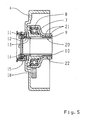
- the two sleeve members 9 and 10 are connected to each other via a ball screw drive 20.
- the other reference numerals correspond to Fig. 2 .
- the sleeve member 9 is driven and causes by its rotation while maintaining the axial position that the sleeve member 10 is axially displaced.
- a plurality of balls 21 are arranged in the raceway 22 between the sleeve members 9 and 10 and transmit the rotational movement of the sleeve member 9 in the axial movement of the sleeve member 10th
Landscapes
- Engineering & Computer Science (AREA)
- General Engineering & Computer Science (AREA)
- Mechanical Engineering (AREA)
- Physics & Mathematics (AREA)
- Electromagnetism (AREA)
- Mechanical Operated Clutches (AREA)
- Hydraulic Clutches, Magnetic Clutches, Fluid Clutches, And Fluid Joints (AREA)
Description
- Die vorliegende Erfindung betrifft einen elektromechanischen Kupplungsaktuator zum Betätigen einer Kupplung eines automatisierten Schaltgetriebes eines Fahrzeuges gemäß der im Oberbegriff des Patentanspruches 1 näher definierten Art. Ein gattungsgemäßer Kupplungsaktuator ist aus
WO-A-03/087609 - Ein anderer elektromechanischer Kupplungsaktuator ist aus der Druckschrift
EP 0 716 242 B1 bekannt. Der Kupplungsaktuator umfasst einen Elektromotor als Antrieb, der mit einem Ausrückmechanismus gekoppelt ist. - Der Ausrückmechanismus umfasst ein koaxial zu einer Getriebewelle angeordnetes Gehäuse und stützt sich an einer getriebegehäuseseitigen Halterung ab. Die Drehbewegung des Elektromotors wird über eine Schnecke in eine Axialbewegung zum Betätigen des Ausrücklagers der Kupplung umgesetzt, wobei die Schnecke mit einer Verzahnung an dem Gehäuse in Eingriff steht. Dazu stützt sich das Gehäuse an seiner Innenseite an einem Steilgewinde ab, so dass das drehende Gehäuse zum Betätigen des Ausrücklagers in axiale Richtung bewegt wird.
- Ein weiterer die Ausrückbewegung über ein Gewinde übertragener Kupplungsaktuator ist aus der Druckschrift
DE 41 40 122 C2 bekannt. Als Antrieb ist auch dort ein Elektromotor vorgesehen, der über ein die Übersetzung veränderndes Wälzgetriebe eine Schraubspindel eines Schraubgetriebes antreibt, um die Drehbewegung des Elektromotors in eine axiale Bewegung zum Betätigen der Kupplung umzuwandeln. Der Schraubeingriff zwischen der Spindelmutter und der Schraubspindel erfolgt durch einen reibungsarmen Kugelumlauf. - Aus der Druckschrift
US 5,910,061 ist ein weiterer Kupplungsaktuator bekannt, welcher ein Kupplungssteuergerät zur Ansteuerung einer elektromagnetischen Spule umfasst, welche durch Energiebeaufschlagung derart angeregt wird, dass ein Kupplungsring betätigt wird, um letztendlich eine Betätigungskraft über ein Planetengetriebe auf eine Druckplatte der Kupplung zum Betätigen derselben auszuüben. - Die bekannten Kupplungsaktuatoren benötigen eine Vielzahl von Bauteilen für den Ausrückmechanismus, um die Kupplung in gewünschter Weise betätigen zu können. Somit sind die bekannten Kupplungsaktuatoren kostenintensiv und erfordern einen erheblichen Bauraum.
- Demnach liegt der vorliegenden Erfindung die Aufgabe zugrunde, einen elektromechanischen Kupplungsaktuator der eingangs beschriebenen Gattung vorzuschlagen, welcher möglichst einfach aufgebaut ist und einen geringen Bauraumbedarf hat. Außerden soll der Kupplungsaktuator die Einstellung möglicher Einbautoleranzen zwischen der Kupplung und dem Getriebe erlauben
- Diese Aufgabe wird erfindungsgemäß durch die Merkmale des Patentanspruches 1 gelöst. Weitere vorteilhafte Ausgestaltungen ergeben sich insbesondere aus den Unteransprüchen.
- Demnach wird ein elektromechanischer Kupplungsaktuator an einer Getriebewelle zum Betätigen einer Kupplung eines automatisierten Schaltgetriebes oder dergleichen eines Fahrzeuges vorgeschlagen. Der erfindungsgemäße Kupplungsaktuator weist als Antrieb einen Elektromotor und einen die Drehbewegung des Elektromotors in eine Axialbewegung des Ausrücklagers der Kupplung umwandelnden Ausrückmechanismus auf, der koaxial zur Getriebewelle in der Art eines elektromechanischen Zentralausrückers angeordnet ist, wobei der Ausrückmechanismus ein Drehgehäuse umfasst, an dem ein erstes Hülsenelement angeordnet ist, welches in axialer Richtung mit einem zweiten, korrespondieren Hülsenelement zum axialen Verschieben des Ausrücklagers in Wirkverbindung steht, wobei an dem zweiten Hülsenelement kupplungsseitig eine Zwischenhülse angeordnet ist, welche überlappend in einer Innendurchmesserstufe des zweiten Hülsenelements anliegt. Infolgedessen kann ein gewünschter Abstand zwischen diesen beiden Bauteilen zum Ausgleich von Bauteiltoleranzen und zum Spielausgleich eingestellt werden.
- Auf diese Weise wird ein konstruktiv besonders einfach ausgestalteter Ausrückmechanismus bei dem erfindungsgemäßen Kupplungsaktuator realisiert, der aufgrund seiner kompakten Anordnung und seiner wenigen erforderlichen Bauteile auch besonders bauraumsparend in dem Getriebegehäuse untergebracht werden kann. Die sich durch die Bauteilreduktion ergebene kompakte Bauweise erlaubt die Betätigung der Kupplung auch z. B. ohne die Verwendung einer Ausrückgabel.
- Im Rahmen einer möglichen Ausführungsform der vorliegenden Erfindung kann vorgesehen sein, dass das Drehgehäuse mit dem ersten Hülsenelement an einem Außengehäuse oder dergleichen drehbar gelagert ist. Infolge dessen sind Drehbewegungen des ersten Hülsenelements möglich, ohne dass dabei eine axiale Bewegung erfolgt. Somit kann das zweite Hülsenelement, welches vorzugsweise drehfest an dem Außengehäuse gelagert ist, durch die Drehbewegung des ersten Hülsenelements axial verschoben werden, da die beiden Hülsenelemente in entsprechender Wirkverbindung stehen.
- Um die Wirkverbindung zwischen den beiden Hülsenelementen auf einfachste Weise zu realisieren, können die einander zugewandten axialen Stirnseitenbereiche oder auch andere Bereiche der Hülsenelemente geeignet profiliert sein. Es können beliebige Profilierungen verwendet werden, die es ermöglichen, dass die Drehbewegung des ersten Hülsenelements in eine axiale Bewegung des zweiten Hülsenelements umgewandelt wird.
- Vorzugsweise können die Hülsenelemente als Profilierung z. B. Ausnehmungen oder dergleichen aufweisen. Diese Ausnehmungen können periodisch ausgeführt sein, sodass sie einen etwa rampenförmigen Verlauf der Stirnseitenbereiche bilden. Es sind auch andere Verläufe an den einander zugewandten Stirnseitenbereiche der Hülsenelemente möglich.
- Unabhängig von dem gewählten Verlauf der Stirnseitenbereiche sollen diese quasi formschlüssig ineinander greifen, so dass die Stirnseitenbereiche durch eine Drehung des ersten Hülsenelements entlang ihrer profilierten Formen gleiten können. Beispielsweise bei einem rampenförmigen Verlauf der einander zugewandten Stirnseitenbereiche kann das erste Hülsenelement aufgrund des gewählten Rampenwinkels der Rampe das zweite Hülsenelement automatisch axial verschieben. Der Rampenwinkel der Rampe gibt dabei den Umfang der axialen Bewegung infolge der Drehung vor. Bei den rampenförmigen Verläufen ist der Rampenwinkel der Rampe im Wesentlichen konstant. Es sind aber auch andere Formen denkbar.
- Eine nächste Weiterbildung der Erfindung kann vorsehen, dass die Zwischenhülse über zumindest ein Federelement oder dergleichen an dem Ausrücklager der Kupplung angeordnet ist. Auf diese Weise kann eine vorbestimmte Vorspannkraft auf das Ausrücklager auch im eingekuppelten Zustand aufgebracht werden. Es sind auch andere Verbindungsmöglichkeiten denkbar.
- Eine konstruktiv einfache Möglichkeit einen Antrieb des Drehgehäuses des Ausrückmechanismus zu realisieren, liegt darin, dass die Abtriebsseite des Elektromotors mit einem Zwischenrad oder dergleichen gekoppelt ist, welches das Drehgehäuse antreibt. Dazu kann beispielsweise das Zwischenrad mit einem Zahnsegment oder dergleichen des Drehgehäuses in Eingriff stehen. Infolgedessen kann die Drehbewegung des Elektromotors in eine entsprechende Drehbewegung des Drehgehäuses zum Betätigen der Kupplung umgesetzt werden.
- Um die Drehbewegung bzw. die Schwenkbewegung des Drehgehäuses zu führen, kann im Rahmen einer nächsten Ausgestaltung der Erfindung vorgesehen sein, dass das Drehgehäuse mit einem schwenkbaren Führungselement, wie z. B. einem Federbein oder dergleichen verbunden ist. Infolgedessen wird die Schwenkbewegung des Drehgehäuses durch das gelenkig angebundene Führungselement geführt. Zudem kann durch einen verwendeten Kraftspeicher auch eine Kraftunterstützung erfolgen, um den Elektromotor bei der Betätigung der Kupplung zu unterstützen.
- In einer weiteren vorteilhaften Ausgestaltung können die beiden Hülsenelemente über einen Spindelantrieb miteinander verbunden sein, wozu der Innenmantel des einen der Hülsenelemente und der Außenmantel des anderen Hülsenelementes profiliert sind. Vorzugsweise eignet sich dazu eine Kugelumlaufspindel.
- Es ist auch denkbar, dass der Elektromotor über eine Übersetzung, wie z. B. einen Riemenantrieb oder andere Getriebe mit dem Ausrückmechanismus gekoppelt ist. Vorzugsweise kann der Elektromotor an dem Außengehäuse angeflanscht sein.
- Nachfolgend wird die vorliegende Erfindung anhand der Zeichnungen näher erläutert.
- Es zeigen:
- Fig. 1
- eine geschnittene Teilansicht eines Getriebegehäuses mit einer Kupplung und einer möglichen Ausführungsvariante eines elektromechanischen Kupplungsaktuators;
- Fig. 2
- eine vergrößerte Ansicht des Kupplungsaktuators gemäß
Fig. 1 ; - Fig. 3
- eine vergrößerte quer geschnittene Ansicht gemäß
Fig. 2 ; - Fig. 4
- eine Teilansicht einer Draufsicht auf in die Ebene abwickelte Hülsenelemente des Kupplungsaktuators und
- Fig. 5
- eine geänderte Ausführung mit Spindelantrieb.
- In den
Fig. 1 bis 4 ist eine mögliche Ausführungsform eines elektromechanischen Kupplungsaktuators gezeigt. Der erfindungsgemäße Kupplungsaktuator ist in einem Getriebegehäuse 1 eines automatisierten Schaltgetriebes eines Fahrzeuges angeordnet. In dem Getriebegehäuse 1 ist eine zu betätigende Kupplung 2 aufgenommen. - Der in
Fig. 2 vergrößert dargestellte Kupplungsaktuator ist koaxial zu der Getriebewelle 3 angeordnet. Der Kupplungsaktuator besitzt ein Außengehäuse 4, an dem ein Elektromotor 5 als Antrieb angeflanscht ist. Die Drehbewegung des Elektromotors 5 wird über ein Zwischenrad 6 zu einem Ausrückmechanismus des Kupplungsaktuators übertragen. Der Ausrückmechanismus umfasst im Wesentlichen ein Drehgehäuse 7, welches drehbar über ein Lager 8 an dem Außengehäuse 4 gelagert ist. - Das Drehgehäuse 7 ist mit einem ersten Hülsenelement 9 verbunden, so dass die Drehbewegung des Drehgehäuses 7 auf das erste Hülsenelement 9 übertragen wird. Das erste, drehbar gelagerte Hülsenelement 9 steht in axialer Richtung mit einem zweiten korrespondierenden Hülsenelement 10 zum axialen Verschieben des Ausrücklagers 11 in Wirkverbindung. Das zweite Hülsenelement 10 ist im Gegensatz zum ersten Hülsenelement 9 drehfest an dem Außengehäuse 4 gelagert, so dass durch die Drehung des ersten Hülsenelements 9 eine axiale Bewegung des zweiten Hülsenelements 10 erreicht werden kann.
- Die Wirkverbindung zwischen den beiden Hülsenelementen 9, 10 wird durch eine geeignete Profilierung der einander zugewandten axialen Stirnseitenbereiche der Hülsenelemente 9, 10 realisiert. Die Profilierung ist als etwa rampenförmiger Verlauf 19, 19' bei den Hülsenelementen 9, 10 ausgeführt, wie dies insbesondere aus
Fig.4 ersichtlich ist. - In
Fig. 4 sind die Hülsenelemente 9, 10 in eine Ebene abgewickelt dargestellt. Aus dieser Teilansicht wird deutlich, dass die rampenförmigen Verläufe 19, 19' der Hülsenelemente 9, 10 derart korrespondieren, dass diese zumindest teilweise je nach Betätigungszustand formschlüssig aneinander liegen. Die Spitzen der Rampen jedes rampenförmigen Verlaufes 19, 19' sind bei der gezeigten Ausführungsform abgeflacht. Die Rampen sind mit einem vorbestimmten Winkel bzw. mit einer vorbestimmten Steigung ausgeführt. - Durch die Drehung des Drehgehäuses 7 und des damit verbundenen ersten Hülsenelements 9 können die rampenförmigen Verläufe 19, 19' der zugewandten Stirnseitenbereiche aneinander gleiten. In Abhängigkeit der Steigung bzw. des Winkels der Rampen der Verläufe 19, 19' kann das zweite Hülsenelement 10 in Abhängigkeit der Drehrichtung des ersten Hülsenelements 9 axial in der Zeichnungsebene der
Fig. 1 und2 nach links oder rechts bewegt werden. Aufgrund der Axialbewegung kann die Kupplung 2 durch das zweite Hülsenelement 10 ausgerückt oder eingerückt werden. - An dem zweiten Hülsenelement 10 schließt sich kupplungsseitig eine Zwischenhülse 12 an, wie aus
Fig. 2 ersichtlich ist. Die Zwischenhülse 12 liegt überlappend an einer Innendurchmesserstufe 13 des zweiten Hülsenelements 10 an. Das Ausrücklager 11 zum Betätigen der Kupplung 2 ist über Befestigungsschrauben 14 an der Zwischenhülse 12 befestigt. Um eine Vorspannkraft auf das Ausrücklager 14 auch im eingekuppelten Zustand aufbringen zu können, sind mehrere Federn 15 zwischen der Zwischenhülse 12 und dem Ausrücklager 11 vorgesehen. Durch das Zwischenstück 12 können Einbautoleranzen von Kupplung und Getriebe ausgeglichen werden. - Insbesondere aus
Fig. 3 ist ersichtlich, dass die Schwenkbewegung des Drehgehäuses 7 des Ausrückmechanismus über ein Führungselement 16 geführt wird. Das Führungselement 16 ist gelenkig an dem Außengehäuse 4 befestigt. Das Führungselement 16 ist mehrteilig ausgeführt und umfasst einen Kraftspeicher 17, der die Drehbewegung bzw. die Schwenkbewegung des Drehgehäuses 7 unterstützt, um den Elektromotor 5 zu entlasten. - Um die Drehbewegung des Elektromotors 5 über das Zwischenrad 6 auf den Ausrückmechanismus des Kupplungsaktuators zu übertragen, steht das Zwischenrad 6 mit einem Zahnradsegment 18 in Eingriff. Das Zahnradsegment 18 ist an dem Außenumfang des Drehgehäuses 7 angeordnet.
- In der
Fig. 5 sind die beiden Hülsenelemente 9 und 10 über einen Kugelumlaufspindelantrieb 20 miteinander verbunden. Die weiteren Bezugszeichen entsprechen derFig. 2 . Auch hier wird das Hülsenelement 9 angetrieben und bewirkt durch seine Verdrehung unter Beibehaltung der axialen Position, dass das Hülsenelement 10 axial verschoben wird. Dazu sind eine Vielzahl von Kugeln 21 in der Laufbahn 22 zwischen den Hülsenelementen 9 und 10 angeordnet und übertragen die Drehbewegung des Hülsenelementes 9 in die axiale Bewegung des Hülsenelementes 10. -
- 1
- Getriebegehäuse
- 2
- Kupplung
- 3
- Getriebewelle
- 4
- Außengehäuse
- 5
- Elektromotor
- 6
- Zwischenrad
- 7
- Drehgehäuse
- 8
- Lager
- 9
- erstes Hülsenelement
- 10
- zweites Hülsenelement
- 11
- Ausrücklager
- 12
- Zwischenhülse
- 13
- Innendurchmesserstufe
- 14
- Befestigungsschraube
- 15
- Feder
- 16
- Führungselement
- 17
- Kraftspeicher
- 18
- Zahnradsegment
- 19, 19'
- rampenförmiger Verlauf
- 20
- Kugelumlaufspindelantrieb
- 21
- Kugel
- 22
- Laufbahn
Claims (13)
- Elektromechanischer Kupplungsaktuator (1) an einer Getriebewelle (3) zum Betätigen einer Kupplung (2) eines automatisierten Schaltgetriebes eines Fahrzeuges, mit einem Elektromotor (5) als Antrieb und einem die Drehbewegung des Elektromotors (5) in eine Axialbewegung des Ausrücklagers (11) der Kupplung (2) umwandelnden Ausrückmechanismus, der koaxial zur Getriebewelle (3) angeordnet ist, wobei der Ausrückmechanismus ein Drehgehäuse (7) umfasst, an dem ein erstes Hülsenelement (9) angeordnet ist, welches in axialer Richtung mit einem zweiten, korrespondierenden Hülsenelement (10) zum axialen Verschieben des Ausrücklagers (11) in Wirkverbindung steht, dadurch gekennzeichnet, dass an dem zweiten Hülsenelement (10) kupplungsseitig eine Zwischenhülse (12) angeordnet ist, welche überlappend an einer Innendurchmesserstufe (13) des zweiten Hülsenelements (10) anliegt.
- Kupplungsaktuator nach Anspruch 1, dadurch gekennzeichnet, dass das Drehgehäuse (7) mit dem ersten Hülsenelement (9) an einem Außengehäuse (4) drehbar gelagert ist, und dass das zweite Hülsenelement (10) drehfest an dem Außengehäuse (4) gelagert ist, sodass das zweite Hülsenelement (10) durch die Drehung des ersten Hülsenelement (9) axial bewegbar ist.
- Kupplungsaktuator nach Anspruch 1 oder 2, dadurch gekennzeichnet, dass die einander zugewandten axialen Stirnseitenbereiche der Hülsenelemente (9, 10) profiliert sind.
- Kupplungsaktuator nach Anspruch 3, dadurch gekennzeichnet, dass jedes Hülsenelement (9.10) als Profilierung einen etwa rampenförmigen Verlauf (19, 19') an dem Stirnseitenbereich aufweist.
- Kupplungsaktuator nach Anspruch 4, dadurch gekennzeichnet, dass die rampenförmigen Verläufe (19, 19') der einander zugewandten Stirnseitenbereiche der Hülsenelemente (9, 10) formschlüssig im Eingriff stehen.
- Kupplungsaktuator nach Anspruch 1 oder 2, dadurch gekennzeichnet, dass der Innenmantel des einen Hülsenelements (9, 10) und der Außenmantel des anderen Hülsenelementes (10, 9) profiliert sind.
- Kupplungsaktuator nach Anspruch 6, dadurch gekennzeichnet, dass zwischen dem ersten und dem zweiten Hülsenelement (9, 10) ein Kugelumlaufspindelantrieb (20) ausgebildet ist.
- Kupplungsaktuator nach Anspruch 1, dadurch gekennzeichnet, dass die Zwischenhülse (12) über zumindest ein Federelement (15) an dem Ausrücklager (11) der Kupplung (2) vorgespannt ist.
- Kupplungsaktuator nach einem der vorangehenden Ansprüche, dadurch gekennzeichnet, dass der Abtrieb des Elektromotors (5) mit einem Zwischenrad (6) zum Antrieb des Drehgehäuses (7) gekoppelt ist.
- Kupplungsaktuator nach einem der vorangehenden Ansprüche, dadurch gekennzeichnet, dass das Zwischenrad (6) mit einem Zahnradsegment (18) des Drehgehäuses (7) in Eingriff steht.
- Kupplungsaktuator nach einem der vorangehenden Ansprüche, dadurch gekennzeichnet, dass das Drehgehäuse (7) mit einem Führungselement (16) verbunden ist, wobei das Führungselement (16) gelenkig an dem Außengehäuse (4) befestigt ist.
- Kupplungsaktuator nach Anspruch 11, dadurch gekennzeichnet, dass das Führungselement (16) mit einem Kraftspeicher (17) zur Unterstützung der Drehbewegung des Drehgehäuses (7) ausgerüstet ist.
- Kupplungsaktuator nach einem der vorangehenden Ansprüche, dadurch gekennzeichnet, dass der Elektromotor (5) an dem Außengehäuse (4) angeflanscht ist.
Applications Claiming Priority (2)
| Application Number | Priority Date | Filing Date | Title |
|---|---|---|---|
| DE102007011766A DE102007011766A1 (de) | 2007-03-10 | 2007-03-10 | Elektromechanischer Kupplungsaktuator |
| PCT/EP2008/052342 WO2008110457A1 (de) | 2007-03-10 | 2008-02-27 | Elektromechanischer kupplungsaktuator |
Publications (2)
| Publication Number | Publication Date |
|---|---|
| EP2118509A1 EP2118509A1 (de) | 2009-11-18 |
| EP2118509B1 true EP2118509B1 (de) | 2011-11-09 |
Family
ID=39512556
Family Applications (1)
| Application Number | Title | Priority Date | Filing Date |
|---|---|---|---|
| EP08717154A Not-in-force EP2118509B1 (de) | 2007-03-10 | 2008-02-27 | Elektromechanischer kupplungsaktuator |
Country Status (5)
| Country | Link |
|---|---|
| EP (1) | EP2118509B1 (de) |
| JP (1) | JP2010520972A (de) |
| AT (1) | ATE532983T1 (de) |
| DE (1) | DE102007011766A1 (de) |
| WO (1) | WO2008110457A1 (de) |
Family Cites Families (18)
| Publication number | Priority date | Publication date | Assignee | Title |
|---|---|---|---|---|
| JPH0819971B2 (ja) * | 1987-12-10 | 1996-03-04 | アイシン・エィ・ダブリュ株式会社 | 摩擦係合装置用アクチュエータ |
| DE4140122C2 (de) | 1991-12-05 | 1994-07-07 | Daimler Benz Ag | Anordnung zur elektromotorischen Betätigung einer reibschlüssigen Verbindung zwischen zwei Getriebegliedern eines Zahnrädergetriebes eines Kraftfahrzeuges |
| DE4443649A1 (de) | 1994-12-08 | 1996-06-13 | Opel Adam Ag | Elektromotorische Betätigung einer Reibscheibenkupplung |
| DE19700936A1 (de) * | 1996-01-24 | 1997-07-31 | Luk Getriebe Systeme Gmbh | Vorrichtung zur Betätigung eines betätigbaren Bauteiles |
| US5910061A (en) | 1997-09-30 | 1999-06-08 | Eaton Corporation | Ball ramp driveline clutch actuator with unidirectional apply |
| GB2338769B (en) * | 1998-04-09 | 2003-01-22 | Luk Lamellen & Kupplungsbau | Operating device for a clutch |
| US6012561A (en) * | 1998-09-15 | 2000-01-11 | Chrysler Corporation | Dual clutch design for and electro-mechanical automatic transmission having a dual input shaft |
| JP4135345B2 (ja) * | 2001-09-27 | 2008-08-20 | 日本精工株式会社 | 自動クラッチレリーズ装置及びクラッチ装置 |
| DE10391277D2 (de) * | 2002-04-06 | 2005-02-24 | Luk Lamellen & Kupplungsbau | Kupplungsbetätigungen |
| DE10216136A1 (de) * | 2002-04-12 | 2003-10-23 | Ina Schaeffler Kg | Elektromotorische Betätigungseinrichtung |
| DE10236516A1 (de) * | 2002-08-09 | 2004-02-19 | Zf Sachs Ag | Elektromechanische Kupplung und elektromechanisches System |
| AU2003297737A1 (en) * | 2002-12-09 | 2004-06-30 | Yves J. Kemper | Coaxial friction clutch actuator system |
| JP2004239424A (ja) * | 2003-02-10 | 2004-08-26 | Exedy Corp | クラッチ操作機構 |
| JP2004308709A (ja) * | 2003-04-03 | 2004-11-04 | Exedy Corp | クラッチ操作機構 |
| US6808053B2 (en) * | 2003-02-21 | 2004-10-26 | New Venture Gear, Inc. | Torque transfer device having an electric motor/brake actuator and friction clutch |
| JP4517702B2 (ja) * | 2004-03-30 | 2010-08-04 | アイシン精機株式会社 | クラッチ用アクチュエータ |
| US6988604B2 (en) * | 2004-04-19 | 2006-01-24 | Borgwarner Inc. | Friction clutch pack having a motor driven ball ramp operator |
| DE502006005316D1 (de) * | 2005-05-19 | 2009-12-24 | Luk Lamellen & Kupplungsbau | Vorrichtung zur Betätigung einer Kupplung |
-
2007
- 2007-03-10 DE DE102007011766A patent/DE102007011766A1/de not_active Withdrawn
-
2008
- 2008-02-27 JP JP2009552171A patent/JP2010520972A/ja active Pending
- 2008-02-27 EP EP08717154A patent/EP2118509B1/de not_active Not-in-force
- 2008-02-27 WO PCT/EP2008/052342 patent/WO2008110457A1/de not_active Ceased
- 2008-02-27 AT AT08717154T patent/ATE532983T1/de active
Also Published As
| Publication number | Publication date |
|---|---|
| DE102007011766A1 (de) | 2008-09-11 |
| WO2008110457A1 (de) | 2008-09-18 |
| EP2118509A1 (de) | 2009-11-18 |
| JP2010520972A (ja) | 2010-06-17 |
| ATE532983T1 (de) | 2011-11-15 |
Similar Documents
| Publication | Publication Date | Title |
|---|---|---|
| EP2247867B1 (de) | Betätigungsanordnung für schaltelemente eines getriebes | |
| EP2098743B1 (de) | Stellmechanismus zum Ein- und Ausrücken einer Trennkupplung mit drehbarem Kurvensegment | |
| EP2694355B1 (de) | Elektromechanische servolenkung mit spielausgleich für das schneckenradgetriebe | |
| DE102010029401B4 (de) | Parksperrenanordnung mit Notentriegelung | |
| EP2069652B1 (de) | Doppelkupplung für ein doppelkupplungsgetriebe | |
| EP2345569B1 (de) | Schraubradgetriebe für eine Lenkung eines Kraftfahrzeugs | |
| EP1302688A2 (de) | Betätigungseinrichtung für eine Reibungskupplungseinrichtung, gegebenenfalls Doppel- oder Mehrfach- Reibungskupplungseinrichtung | |
| DE102010002285A1 (de) | Schraubradgetriebe für eine Lenkung eines Kraftfahrzeugs | |
| DE112008002124T5 (de) | Linearantriebsaktuator für ein bewegliches Fahrzeugpaneel | |
| WO2015082205A2 (de) | Elektromechanisch betätigbare trommelbremse | |
| DE102015217164B4 (de) | Baugruppe mit einer Reibeinrichtung | |
| DE19700935A1 (de) | Vorrichtung zur Betätigung eines Aggregates im Antriebsstrang eines Kraftfahrzeuges | |
| DE102010026968B4 (de) | Winde sowie Baumaschine oder Hebegerät | |
| DE102012206936A1 (de) | Hybridgetriebe | |
| EP4130515B1 (de) | Antriebsvorrichtung für eine verstellbare fahrzeugklappe | |
| DE102021213456A1 (de) | Spindelantrieb sowie Verfahren zum Betreiben eines solchen | |
| DE102021203008A1 (de) | Betätigungseinrichtung für eine elektromechanisch betätigbare Kraftfahrzeugbremse | |
| WO2013013940A1 (de) | Parksperre | |
| DE602006000908T2 (de) | Doppelkupplungsgetriebe für Kraftfahrzeug | |
| EP1905147B1 (de) | Getriebemotor | |
| EP3698071B1 (de) | Betätigungsanordnung für eine parksperre für ein kraftfahrzeug | |
| EP2732177A1 (de) | Formschlusskupplungsbetätigungsvorrichtung eines kraftfahrzeuggetriebes | |
| DE102010018000A1 (de) | Drehmomenteinstellvorrichtung | |
| EP0716242A1 (de) | Elektromotorische Betätigung einer Reibscheibenkupplung | |
| DE102012103857A1 (de) | Vorrichtung zum Andrücken einer Schnecke oder eines Schraubritzels an ein Schneckenrad oder an ein Schraubrad |
Legal Events
| Date | Code | Title | Description |
|---|---|---|---|
| PUAI | Public reference made under article 153(3) epc to a published international application that has entered the european phase |
Free format text: ORIGINAL CODE: 0009012 |
|
| 17P | Request for examination filed |
Effective date: 20090723 |
|
| AK | Designated contracting states |
Kind code of ref document: A1 Designated state(s): AT BE BG CH CY CZ DE DK EE ES FI FR GB GR HR HU IE IS IT LI LT LU LV MC MT NL NO PL PT RO SE SI SK TR |
|
| DAX | Request for extension of the european patent (deleted) | ||
| GRAP | Despatch of communication of intention to grant a patent |
Free format text: ORIGINAL CODE: EPIDOSNIGR1 |
|
| GRAS | Grant fee paid |
Free format text: ORIGINAL CODE: EPIDOSNIGR3 |
|
| GRAA | (expected) grant |
Free format text: ORIGINAL CODE: 0009210 |
|
| AK | Designated contracting states |
Kind code of ref document: B1 Designated state(s): AT BE BG CH CY CZ DE DK EE ES FI FR GB GR HR HU IE IS IT LI LT LU LV MC MT NL NO PL PT RO SE SI SK TR |
|
| REG | Reference to a national code |
Ref country code: GB Ref legal event code: FG4D Free format text: NOT ENGLISH |
|
| REG | Reference to a national code |
Ref country code: CH Ref legal event code: EP |
|
| REG | Reference to a national code |
Ref country code: IE Ref legal event code: FG4D Free format text: LANGUAGE OF EP DOCUMENT: GERMAN |
|
| REG | Reference to a national code |
Ref country code: SE Ref legal event code: TRGR |
|
| REG | Reference to a national code |
Ref country code: DE Ref legal event code: R096 Ref document number: 502008005526 Country of ref document: DE Effective date: 20120216 |
|
| REG | Reference to a national code |
Ref country code: NL Ref legal event code: VDEP Effective date: 20111109 |
|
| LTIE | Lt: invalidation of european patent or patent extension |
Effective date: 20111109 |
|
| PG25 | Lapsed in a contracting state [announced via postgrant information from national office to epo] |
Ref country code: NO Free format text: LAPSE BECAUSE OF FAILURE TO SUBMIT A TRANSLATION OF THE DESCRIPTION OR TO PAY THE FEE WITHIN THE PRESCRIBED TIME-LIMIT Effective date: 20120209 Ref country code: IS Free format text: LAPSE BECAUSE OF FAILURE TO SUBMIT A TRANSLATION OF THE DESCRIPTION OR TO PAY THE FEE WITHIN THE PRESCRIBED TIME-LIMIT Effective date: 20120309 Ref country code: LT Free format text: LAPSE BECAUSE OF FAILURE TO SUBMIT A TRANSLATION OF THE DESCRIPTION OR TO PAY THE FEE WITHIN THE PRESCRIBED TIME-LIMIT Effective date: 20111109 |
|
| PGFP | Annual fee paid to national office [announced via postgrant information from national office to epo] |
Ref country code: FR Payment date: 20120221 Year of fee payment: 5 |
|
| PG25 | Lapsed in a contracting state [announced via postgrant information from national office to epo] |
Ref country code: NL Free format text: LAPSE BECAUSE OF FAILURE TO SUBMIT A TRANSLATION OF THE DESCRIPTION OR TO PAY THE FEE WITHIN THE PRESCRIBED TIME-LIMIT Effective date: 20111109 Ref country code: GR Free format text: LAPSE BECAUSE OF FAILURE TO SUBMIT A TRANSLATION OF THE DESCRIPTION OR TO PAY THE FEE WITHIN THE PRESCRIBED TIME-LIMIT Effective date: 20120210 Ref country code: PT Free format text: LAPSE BECAUSE OF FAILURE TO SUBMIT A TRANSLATION OF THE DESCRIPTION OR TO PAY THE FEE WITHIN THE PRESCRIBED TIME-LIMIT Effective date: 20120309 Ref country code: PL Free format text: LAPSE BECAUSE OF FAILURE TO SUBMIT A TRANSLATION OF THE DESCRIPTION OR TO PAY THE FEE WITHIN THE PRESCRIBED TIME-LIMIT Effective date: 20111109 Ref country code: HR Free format text: LAPSE BECAUSE OF FAILURE TO SUBMIT A TRANSLATION OF THE DESCRIPTION OR TO PAY THE FEE WITHIN THE PRESCRIBED TIME-LIMIT Effective date: 20111109 Ref country code: LV Free format text: LAPSE BECAUSE OF FAILURE TO SUBMIT A TRANSLATION OF THE DESCRIPTION OR TO PAY THE FEE WITHIN THE PRESCRIBED TIME-LIMIT Effective date: 20111109 Ref country code: SI Free format text: LAPSE BECAUSE OF FAILURE TO SUBMIT A TRANSLATION OF THE DESCRIPTION OR TO PAY THE FEE WITHIN THE PRESCRIBED TIME-LIMIT Effective date: 20111109 |
|
| REG | Reference to a national code |
Ref country code: IE Ref legal event code: FD4D |
|
| PG25 | Lapsed in a contracting state [announced via postgrant information from national office to epo] |
Ref country code: CY Free format text: LAPSE BECAUSE OF FAILURE TO SUBMIT A TRANSLATION OF THE DESCRIPTION OR TO PAY THE FEE WITHIN THE PRESCRIBED TIME-LIMIT Effective date: 20111109 |
|
| PGFP | Annual fee paid to national office [announced via postgrant information from national office to epo] |
Ref country code: IT Payment date: 20120220 Year of fee payment: 5 |
|
| PG25 | Lapsed in a contracting state [announced via postgrant information from national office to epo] |
Ref country code: SK Free format text: LAPSE BECAUSE OF FAILURE TO SUBMIT A TRANSLATION OF THE DESCRIPTION OR TO PAY THE FEE WITHIN THE PRESCRIBED TIME-LIMIT Effective date: 20111109 Ref country code: BG Free format text: LAPSE BECAUSE OF FAILURE TO SUBMIT A TRANSLATION OF THE DESCRIPTION OR TO PAY THE FEE WITHIN THE PRESCRIBED TIME-LIMIT Effective date: 20120209 Ref country code: CZ Free format text: LAPSE BECAUSE OF FAILURE TO SUBMIT A TRANSLATION OF THE DESCRIPTION OR TO PAY THE FEE WITHIN THE PRESCRIBED TIME-LIMIT Effective date: 20111109 Ref country code: DK Free format text: LAPSE BECAUSE OF FAILURE TO SUBMIT A TRANSLATION OF THE DESCRIPTION OR TO PAY THE FEE WITHIN THE PRESCRIBED TIME-LIMIT Effective date: 20111109 Ref country code: IE Free format text: LAPSE BECAUSE OF FAILURE TO SUBMIT A TRANSLATION OF THE DESCRIPTION OR TO PAY THE FEE WITHIN THE PRESCRIBED TIME-LIMIT Effective date: 20111109 Ref country code: EE Free format text: LAPSE BECAUSE OF FAILURE TO SUBMIT A TRANSLATION OF THE DESCRIPTION OR TO PAY THE FEE WITHIN THE PRESCRIBED TIME-LIMIT Effective date: 20111109 |
|
| BERE | Be: lapsed |
Owner name: ZF FRIEDRICHSHAFEN A.G. Effective date: 20120228 |
|
| PG25 | Lapsed in a contracting state [announced via postgrant information from national office to epo] |
Ref country code: RO Free format text: LAPSE BECAUSE OF FAILURE TO SUBMIT A TRANSLATION OF THE DESCRIPTION OR TO PAY THE FEE WITHIN THE PRESCRIBED TIME-LIMIT Effective date: 20111109 |
|
| PLBE | No opposition filed within time limit |
Free format text: ORIGINAL CODE: 0009261 |
|
| STAA | Information on the status of an ep patent application or granted ep patent |
Free format text: STATUS: NO OPPOSITION FILED WITHIN TIME LIMIT |
|
| PG25 | Lapsed in a contracting state [announced via postgrant information from national office to epo] |
Ref country code: MC Free format text: LAPSE BECAUSE OF NON-PAYMENT OF DUE FEES Effective date: 20120229 |
|
| REG | Reference to a national code |
Ref country code: CH Ref legal event code: PL |
|
| 26N | No opposition filed |
Effective date: 20120810 |
|
| GBPC | Gb: european patent ceased through non-payment of renewal fee |
Effective date: 20120227 |
|
| PG25 | Lapsed in a contracting state [announced via postgrant information from national office to epo] |
Ref country code: SE Free format text: LAPSE BECAUSE OF NON-PAYMENT OF DUE FEES Effective date: 20120228 Ref country code: CH Free format text: LAPSE BECAUSE OF NON-PAYMENT OF DUE FEES Effective date: 20120229 Ref country code: LI Free format text: LAPSE BECAUSE OF NON-PAYMENT OF DUE FEES Effective date: 20120229 |
|
| REG | Reference to a national code |
Ref country code: DE Ref legal event code: R097 Ref document number: 502008005526 Country of ref document: DE Effective date: 20120810 |
|
| PG25 | Lapsed in a contracting state [announced via postgrant information from national office to epo] |
Ref country code: BE Free format text: LAPSE BECAUSE OF NON-PAYMENT OF DUE FEES Effective date: 20120228 |
|
| PG25 | Lapsed in a contracting state [announced via postgrant information from national office to epo] |
Ref country code: GB Free format text: LAPSE BECAUSE OF NON-PAYMENT OF DUE FEES Effective date: 20120227 |
|
| PG25 | Lapsed in a contracting state [announced via postgrant information from national office to epo] |
Ref country code: FI Free format text: LAPSE BECAUSE OF FAILURE TO SUBMIT A TRANSLATION OF THE DESCRIPTION OR TO PAY THE FEE WITHIN THE PRESCRIBED TIME-LIMIT Effective date: 20111109 |
|
| PG25 | Lapsed in a contracting state [announced via postgrant information from national office to epo] |
Ref country code: MT Free format text: LAPSE BECAUSE OF FAILURE TO SUBMIT A TRANSLATION OF THE DESCRIPTION OR TO PAY THE FEE WITHIN THE PRESCRIBED TIME-LIMIT Effective date: 20111109 |
|
| PG25 | Lapsed in a contracting state [announced via postgrant information from national office to epo] |
Ref country code: ES Free format text: LAPSE BECAUSE OF FAILURE TO SUBMIT A TRANSLATION OF THE DESCRIPTION OR TO PAY THE FEE WITHIN THE PRESCRIBED TIME-LIMIT Effective date: 20120220 |
|
| REG | Reference to a national code |
Ref country code: FR Ref legal event code: ST Effective date: 20131031 |
|
| PG25 | Lapsed in a contracting state [announced via postgrant information from national office to epo] |
Ref country code: IT Free format text: LAPSE BECAUSE OF NON-PAYMENT OF DUE FEES Effective date: 20130227 |
|
| PG25 | Lapsed in a contracting state [announced via postgrant information from national office to epo] |
Ref country code: FR Free format text: LAPSE BECAUSE OF NON-PAYMENT OF DUE FEES Effective date: 20130228 |
|
| REG | Reference to a national code |
Ref country code: AT Ref legal event code: MM01 Ref document number: 532983 Country of ref document: AT Kind code of ref document: T Effective date: 20130227 |
|
| PG25 | Lapsed in a contracting state [announced via postgrant information from national office to epo] |
Ref country code: TR Free format text: LAPSE BECAUSE OF FAILURE TO SUBMIT A TRANSLATION OF THE DESCRIPTION OR TO PAY THE FEE WITHIN THE PRESCRIBED TIME-LIMIT Effective date: 20111109 |
|
| PG25 | Lapsed in a contracting state [announced via postgrant information from national office to epo] |
Ref country code: LU Free format text: LAPSE BECAUSE OF NON-PAYMENT OF DUE FEES Effective date: 20120227 Ref country code: AT Free format text: LAPSE BECAUSE OF NON-PAYMENT OF DUE FEES Effective date: 20130227 |
|
| PG25 | Lapsed in a contracting state [announced via postgrant information from national office to epo] |
Ref country code: HU Free format text: LAPSE BECAUSE OF FAILURE TO SUBMIT A TRANSLATION OF THE DESCRIPTION OR TO PAY THE FEE WITHIN THE PRESCRIBED TIME-LIMIT Effective date: 20080227 |
|
| PGFP | Annual fee paid to national office [announced via postgrant information from national office to epo] |
Ref country code: DE Payment date: 20190212 Year of fee payment: 12 |
|
| REG | Reference to a national code |
Ref country code: DE Ref legal event code: R119 Ref document number: 502008005526 Country of ref document: DE |
|
| PG25 | Lapsed in a contracting state [announced via postgrant information from national office to epo] |
Ref country code: DE Free format text: LAPSE BECAUSE OF NON-PAYMENT OF DUE FEES Effective date: 20200901 |