EP2117758B1 - Réparation par soudage de défauts intérieurs - Google Patents
Réparation par soudage de défauts intérieurs Download PDFInfo
- Publication number
- EP2117758B1 EP2117758B1 EP07704543.3A EP07704543A EP2117758B1 EP 2117758 B1 EP2117758 B1 EP 2117758B1 EP 07704543 A EP07704543 A EP 07704543A EP 2117758 B1 EP2117758 B1 EP 2117758B1
- Authority
- EP
- European Patent Office
- Prior art keywords
- welding
- powder
- crack
- flux
- turbine
- Prior art date
- Legal status (The legal status is an assumption and is not a legal conclusion. Google has not performed a legal analysis and makes no representation as to the accuracy of the status listed.)
- Not-in-force
Links
Images


Classifications
-
- B—PERFORMING OPERATIONS; TRANSPORTING
- B23—MACHINE TOOLS; METAL-WORKING NOT OTHERWISE PROVIDED FOR
- B23K—SOLDERING OR UNSOLDERING; WELDING; CLADDING OR PLATING BY SOLDERING OR WELDING; CUTTING BY APPLYING HEAT LOCALLY, e.g. FLAME CUTTING; WORKING BY LASER BEAM
- B23K10/00—Welding or cutting by means of a plasma
-
- B—PERFORMING OPERATIONS; TRANSPORTING
- B23—MACHINE TOOLS; METAL-WORKING NOT OTHERWISE PROVIDED FOR
- B23K—SOLDERING OR UNSOLDERING; WELDING; CLADDING OR PLATING BY SOLDERING OR WELDING; CUTTING BY APPLYING HEAT LOCALLY, e.g. FLAME CUTTING; WORKING BY LASER BEAM
- B23K26/00—Working by laser beam, e.g. welding, cutting or boring
- B23K26/20—Bonding
- B23K26/32—Bonding taking account of the properties of the material involved
-
- B—PERFORMING OPERATIONS; TRANSPORTING
- B23—MACHINE TOOLS; METAL-WORKING NOT OTHERWISE PROVIDED FOR
- B23K—SOLDERING OR UNSOLDERING; WELDING; CLADDING OR PLATING BY SOLDERING OR WELDING; CUTTING BY APPLYING HEAT LOCALLY, e.g. FLAME CUTTING; WORKING BY LASER BEAM
- B23K26/00—Working by laser beam, e.g. welding, cutting or boring
- B23K26/34—Laser welding for purposes other than joining
- B23K26/342—Build-up welding
-
- B—PERFORMING OPERATIONS; TRANSPORTING
- B23—MACHINE TOOLS; METAL-WORKING NOT OTHERWISE PROVIDED FOR
- B23K—SOLDERING OR UNSOLDERING; WELDING; CLADDING OR PLATING BY SOLDERING OR WELDING; CUTTING BY APPLYING HEAT LOCALLY, e.g. FLAME CUTTING; WORKING BY LASER BEAM
- B23K35/00—Rods, electrodes, materials, or media, for use in soldering, welding, or cutting
- B23K35/02—Rods, electrodes, materials, or media, for use in soldering, welding, or cutting characterised by mechanical features, e.g. shape
- B23K35/0222—Rods, electrodes, materials, or media, for use in soldering, welding, or cutting characterised by mechanical features, e.g. shape for use in soldering, brazing
- B23K35/0244—Powders, particles or spheres; Preforms made therefrom
- B23K35/025—Pastes, creams, slurries
-
- B—PERFORMING OPERATIONS; TRANSPORTING
- B23—MACHINE TOOLS; METAL-WORKING NOT OTHERWISE PROVIDED FOR
- B23K—SOLDERING OR UNSOLDERING; WELDING; CLADDING OR PLATING BY SOLDERING OR WELDING; CUTTING BY APPLYING HEAT LOCALLY, e.g. FLAME CUTTING; WORKING BY LASER BEAM
- B23K35/00—Rods, electrodes, materials, or media, for use in soldering, welding, or cutting
- B23K35/22—Rods, electrodes, materials, or media, for use in soldering, welding, or cutting characterised by the composition or nature of the material
- B23K35/36—Selection of non-metallic compositions, e.g. coatings, fluxes; Selection of soldering or welding materials, conjoint with selection of non-metallic compositions, both selections being of interest
- B23K35/3601—Selection of non-metallic compositions, e.g. coatings, fluxes; Selection of soldering or welding materials, conjoint with selection of non-metallic compositions, both selections being of interest with inorganic compounds as principal constituents
- B23K35/3602—Carbonates, basic oxides or hydroxides
-
- B—PERFORMING OPERATIONS; TRANSPORTING
- B23—MACHINE TOOLS; METAL-WORKING NOT OTHERWISE PROVIDED FOR
- B23K—SOLDERING OR UNSOLDERING; WELDING; CLADDING OR PLATING BY SOLDERING OR WELDING; CUTTING BY APPLYING HEAT LOCALLY, e.g. FLAME CUTTING; WORKING BY LASER BEAM
- B23K35/00—Rods, electrodes, materials, or media, for use in soldering, welding, or cutting
- B23K35/22—Rods, electrodes, materials, or media, for use in soldering, welding, or cutting characterised by the composition or nature of the material
- B23K35/36—Selection of non-metallic compositions, e.g. coatings, fluxes; Selection of soldering or welding materials, conjoint with selection of non-metallic compositions, both selections being of interest
- B23K35/3601—Selection of non-metallic compositions, e.g. coatings, fluxes; Selection of soldering or welding materials, conjoint with selection of non-metallic compositions, both selections being of interest with inorganic compounds as principal constituents
- B23K35/3608—Titania or titanates
-
- B—PERFORMING OPERATIONS; TRANSPORTING
- B23—MACHINE TOOLS; METAL-WORKING NOT OTHERWISE PROVIDED FOR
- B23K—SOLDERING OR UNSOLDERING; WELDING; CLADDING OR PLATING BY SOLDERING OR WELDING; CUTTING BY APPLYING HEAT LOCALLY, e.g. FLAME CUTTING; WORKING BY LASER BEAM
- B23K9/00—Arc welding or cutting
- B23K9/04—Welding for other purposes than joining, e.g. built-up welding
-
- B—PERFORMING OPERATIONS; TRANSPORTING
- B23—MACHINE TOOLS; METAL-WORKING NOT OTHERWISE PROVIDED FOR
- B23P—METAL-WORKING NOT OTHERWISE PROVIDED FOR; COMBINED OPERATIONS; UNIVERSAL MACHINE TOOLS
- B23P6/00—Restoring or reconditioning objects
- B23P6/002—Repairing turbine components, e.g. moving or stationary blades, rotors
- B23P6/007—Repairing turbine components, e.g. moving or stationary blades, rotors using only additive methods, e.g. build-up welding
-
- B—PERFORMING OPERATIONS; TRANSPORTING
- B23—MACHINE TOOLS; METAL-WORKING NOT OTHERWISE PROVIDED FOR
- B23P—METAL-WORKING NOT OTHERWISE PROVIDED FOR; COMBINED OPERATIONS; UNIVERSAL MACHINE TOOLS
- B23P6/00—Restoring or reconditioning objects
- B23P6/04—Repairing fractures or cracked metal parts or products, e.g. castings
- B23P6/045—Repairing fractures or cracked metal parts or products, e.g. castings of turbine components, e.g. moving or stationary blades, rotors, etc.
-
- C—CHEMISTRY; METALLURGY
- C22—METALLURGY; FERROUS OR NON-FERROUS ALLOYS; TREATMENT OF ALLOYS OR NON-FERROUS METALS
- C22C—ALLOYS
- C22C19/00—Alloys based on nickel or cobalt
- C22C19/03—Alloys based on nickel or cobalt based on nickel
- C22C19/05—Alloys based on nickel or cobalt based on nickel with chromium
- C22C19/051—Alloys based on nickel or cobalt based on nickel with chromium and Mo or W
- C22C19/055—Alloys based on nickel or cobalt based on nickel with chromium and Mo or W with the maximum Cr content being at least 20% but less than 30%
-
- C—CHEMISTRY; METALLURGY
- C22—METALLURGY; FERROUS OR NON-FERROUS ALLOYS; TREATMENT OF ALLOYS OR NON-FERROUS METALS
- C22C—ALLOYS
- C22C19/00—Alloys based on nickel or cobalt
- C22C19/07—Alloys based on nickel or cobalt based on cobalt
-
- F—MECHANICAL ENGINEERING; LIGHTING; HEATING; WEAPONS; BLASTING
- F01—MACHINES OR ENGINES IN GENERAL; ENGINE PLANTS IN GENERAL; STEAM ENGINES
- F01D—NON-POSITIVE DISPLACEMENT MACHINES OR ENGINES, e.g. STEAM TURBINES
- F01D5/00—Blades; Blade-carrying members; Heating, heat-insulating, cooling or antivibration means on the blades or the members
- F01D5/005—Repairing methods or devices
-
- B—PERFORMING OPERATIONS; TRANSPORTING
- B23—MACHINE TOOLS; METAL-WORKING NOT OTHERWISE PROVIDED FOR
- B23K—SOLDERING OR UNSOLDERING; WELDING; CLADDING OR PLATING BY SOLDERING OR WELDING; CUTTING BY APPLYING HEAT LOCALLY, e.g. FLAME CUTTING; WORKING BY LASER BEAM
- B23K2101/00—Articles made by soldering, welding or cutting
- B23K2101/001—Turbines
-
- B—PERFORMING OPERATIONS; TRANSPORTING
- B23—MACHINE TOOLS; METAL-WORKING NOT OTHERWISE PROVIDED FOR
- B23K—SOLDERING OR UNSOLDERING; WELDING; CLADDING OR PLATING BY SOLDERING OR WELDING; CUTTING BY APPLYING HEAT LOCALLY, e.g. FLAME CUTTING; WORKING BY LASER BEAM
- B23K2101/00—Articles made by soldering, welding or cutting
- B23K2101/34—Coated articles, e.g. plated or painted; Surface treated articles
-
- B—PERFORMING OPERATIONS; TRANSPORTING
- B23—MACHINE TOOLS; METAL-WORKING NOT OTHERWISE PROVIDED FOR
- B23K—SOLDERING OR UNSOLDERING; WELDING; CLADDING OR PLATING BY SOLDERING OR WELDING; CUTTING BY APPLYING HEAT LOCALLY, e.g. FLAME CUTTING; WORKING BY LASER BEAM
- B23K2103/00—Materials to be soldered, welded or cut
- B23K2103/02—Iron or ferrous alloys
- B23K2103/04—Steel or steel alloys
- B23K2103/05—Stainless steel
-
- B—PERFORMING OPERATIONS; TRANSPORTING
- B23—MACHINE TOOLS; METAL-WORKING NOT OTHERWISE PROVIDED FOR
- B23K—SOLDERING OR UNSOLDERING; WELDING; CLADDING OR PLATING BY SOLDERING OR WELDING; CUTTING BY APPLYING HEAT LOCALLY, e.g. FLAME CUTTING; WORKING BY LASER BEAM
- B23K2103/00—Materials to be soldered, welded or cut
- B23K2103/08—Non-ferrous metals or alloys
-
- B—PERFORMING OPERATIONS; TRANSPORTING
- B23—MACHINE TOOLS; METAL-WORKING NOT OTHERWISE PROVIDED FOR
- B23K—SOLDERING OR UNSOLDERING; WELDING; CLADDING OR PLATING BY SOLDERING OR WELDING; CUTTING BY APPLYING HEAT LOCALLY, e.g. FLAME CUTTING; WORKING BY LASER BEAM
- B23K2103/00—Materials to be soldered, welded or cut
- B23K2103/18—Dissimilar materials
- B23K2103/26—Alloys of Nickel and Cobalt and Chromium
-
- B—PERFORMING OPERATIONS; TRANSPORTING
- B23—MACHINE TOOLS; METAL-WORKING NOT OTHERWISE PROVIDED FOR
- B23K—SOLDERING OR UNSOLDERING; WELDING; CLADDING OR PLATING BY SOLDERING OR WELDING; CUTTING BY APPLYING HEAT LOCALLY, e.g. FLAME CUTTING; WORKING BY LASER BEAM
- B23K2103/00—Materials to be soldered, welded or cut
- B23K2103/50—Inorganic material, e.g. metals, not provided for in B23K2103/02 – B23K2103/26
- B23K2103/52—Ceramics
-
- F—MECHANICAL ENGINEERING; LIGHTING; HEATING; WEAPONS; BLASTING
- F05—INDEXING SCHEMES RELATING TO ENGINES OR PUMPS IN VARIOUS SUBCLASSES OF CLASSES F01-F04
- F05D—INDEXING SCHEME FOR ASPECTS RELATING TO NON-POSITIVE-DISPLACEMENT MACHINES OR ENGINES, GAS-TURBINES OR JET-PROPULSION PLANTS
- F05D2230/00—Manufacture
- F05D2230/20—Manufacture essentially without removing material
- F05D2230/23—Manufacture essentially without removing material by permanently joining parts together
- F05D2230/232—Manufacture essentially without removing material by permanently joining parts together by welding
-
- F—MECHANICAL ENGINEERING; LIGHTING; HEATING; WEAPONS; BLASTING
- F05—INDEXING SCHEMES RELATING TO ENGINES OR PUMPS IN VARIOUS SUBCLASSES OF CLASSES F01-F04
- F05D—INDEXING SCHEME FOR ASPECTS RELATING TO NON-POSITIVE-DISPLACEMENT MACHINES OR ENGINES, GAS-TURBINES OR JET-PROPULSION PLANTS
- F05D2230/00—Manufacture
- F05D2230/80—Repairing, retrofitting or upgrading methods
-
- Y—GENERAL TAGGING OF NEW TECHNOLOGICAL DEVELOPMENTS; GENERAL TAGGING OF CROSS-SECTIONAL TECHNOLOGIES SPANNING OVER SEVERAL SECTIONS OF THE IPC; TECHNICAL SUBJECTS COVERED BY FORMER USPC CROSS-REFERENCE ART COLLECTIONS [XRACs] AND DIGESTS
- Y02—TECHNOLOGIES OR APPLICATIONS FOR MITIGATION OR ADAPTATION AGAINST CLIMATE CHANGE
- Y02T—CLIMATE CHANGE MITIGATION TECHNOLOGIES RELATED TO TRANSPORTATION
- Y02T50/00—Aeronautics or air transport
- Y02T50/60—Efficient propulsion technologies, e.g. for aircraft
Definitions
- the invention relates to a method for welding repair of internal cracks in components.
- Components are tested in a variety of ways after manufacture or after use, which may then identify internal defects that often require repair.
- JP 0 428 4975 discloses a method for welding repair of a crack in a component.
- the object is achieved by a method for welding repair of internal defects according to claim 1.
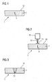
- FIG. 1 shows a component 1, 120, 130, 155, which has a crack 4 in the substrate 7, which does not extend to the outer surface 10, that is completely enclosed in the substrate 7 of the component 1, 120, 130, 155.
- the material of the substrate 7, in particular in turbine components, is preferably a nickel- or cobalt-based alloy.
- nickel- or cobalt-based alloys used can be found in US Pat FIG. 7 ,
- the method can also be applied to steels (on stainless steels, eg SS410) as well as to parts of a compressor or to guide grooves.
- FIG. 2 schematically an arrangement is shown to the crack 4 according to FIG. 1 to repair.
- Internal cracks 4 are detected, preferably by means of an eddy current method 5.
- a so-called “active” flux 13 known in the art is applied to the surface 10 in the region above the crack 4.
- the flux 13 is preferably in powder form.
- the flux 13 is made of powder.
- the flux 13 can preferably also be sprayed on as a suspension or as an alcohol or water-based slip, with or without a binder applied. Likewise, preferably, the powder may be pressed, so be present as a strip or sheet.
- fine-grained powder (+ 1 ⁇ m / -45 ⁇ m) is used.
- TIG welding is used.
- a welding device 16 TIG welding device, laser welding device, etc.
- the skilled person can set laser parameters (duration, intensity, power,%) Material-specifically and component-specifically in order to completely detect a crack 4 in a melting zone 22.
- the melting zone does not extend through the entire thickness of the component 7.
- the melting zone 22 may preferably extend over the entire thickness.
- the edited area is still revised.
- the flux 13 is preferably a powder. Also preferably, the flux 13 may be a powder mixture.
- a composition of SiO 2 or Fe 2 O 3 may be preferably used.
- titanium oxide (0-60wt%), nickel oxide (0-40wt%) and manganese silicide (0-10wt%).
- the improved energy transfer during TIG welding / remelting with surface-active substances is achieved by an enrichment of the arc with electrons.
- the arc is narrowed and thus generates a significantly higher energy density and improved melt bath depth.
- FIG. 4 shows by way of example a gas turbine 100 in a longitudinal partial section.
- the gas turbine 100 has inside a rotatably mounted about a rotation axis 102 rotor 103 with a shaft 101, which is also referred to as a turbine runner.
- an intake housing 104 a compressor 105, for example, a toroidal combustion chamber 110, in particular annular combustion chamber, with a plurality of coaxially arranged burners 107, a turbine 108 and the exhaust housing 109th
- a compressor 105 for example, a toroidal combustion chamber 110, in particular annular combustion chamber, with a plurality of coaxially arranged burners 107, a turbine 108 and the exhaust housing 109th
- the annular combustion chamber 110 communicates with an annular annular hot gas channel 111, for example. There, for example, form four successive turbine stages 112, the turbine 108th
- Each turbine stage 112 is formed, for example, from two blade rings. As seen in the direction of flow of a working medium 113, in the hot gas channel 111 of a row of guide vanes 115, a series 125 formed of rotor blades 120 follows.
- the guide vanes 130 are fastened to an inner housing 138 of a stator 143, whereas the moving blades 120 of a row 125 are attached to the rotor 103 by means of a turbine disk 133, for example.
- air 105 is sucked in and compressed by the compressor 105 through the intake housing 104.
- the compressed air provided at the turbine-side end of the compressor 105 is supplied to the burners 107 where it is mixed with a fuel.
- the mixture is then burned to form the working fluid 113 in the combustion chamber 110.
- the working medium 113 flows along the hot gas channel 111 past the guide vanes 130 and the rotor blades 120.
- the working medium 113 expands in a pulse-transmitting manner so that the rotor blades 120 drive the rotor 103 and drive the machine coupled to it.
- the components exposed to the hot working medium 113 are subject to thermal loads during operation of the gas turbine 100.
- the guide vanes 130 and rotor blades 120 of the first turbine stage 112, viewed in the flow direction of the working medium 113, are subjected to the greatest thermal stress in addition to the heat shield elements lining the annular combustion chamber 110.
- substrates of the components may have a directional structure, i. they are monocrystalline (SX structure) or have only longitudinal grains (DS structure).
- iron-, nickel- or cobalt-based superalloys are used as the material for the components, in particular for the turbine blade 120, 130 and components of the combustion chamber 110.
- Such superalloys are for example from EP 1 204 776 B1 .
- EP 1 306 454 .
- the vane 130 has a guide vane foot (not shown here) facing the inner housing 138 of the turbine 108 and a vane head opposite the vane foot.
- the vane head faces the rotor 103 and fixed to a mounting ring 140 of the stator 143.
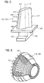
- FIG. 5 shows a perspective view of a blade 120 or guide vane 130 of a turbomachine, which extends along a longitudinal axis 121.
- the turbomachine may be a gas turbine of an aircraft or a power plant for power generation, a steam turbine or a compressor.
- the blade 120, 130 has along the longitudinal axis 121 consecutively a fastening region 400, a blade platform 403 adjacent thereto and an airfoil 406 and a blade tip 415.
- the blade 130 may have at its blade tip 415 another platform (not shown).
- a blade root 183 is formed, which serves for attachment of the blades 120, 130 to a shaft or a disc (not shown).
- the blade root 183 is designed, for example, as a hammer head. Other designs as Christmas tree or Schwalbenschwanzfuß are possible.
- the blade 120, 130 has a leading edge 409 and a trailing edge 412 for a medium flowing past the airfoil 406.
- Such superalloys are for example from EP 1 204 776 B1 .
- EP 1 306 454 .
- the blade 120, 130 can be made by a casting process, also by directional solidification, by a forging process, by a milling process or combinations thereof.
- Workpieces with a monocrystalline structure or structures are used as components for machines which are exposed to high mechanical, thermal and / or chemical stresses during operation.
- Such monocrystalline workpieces takes place e.g. by directed solidification from the melt.
- These are casting processes in which the liquid metallic alloy is transformed into a monocrystalline structure, i. to the single-crystal workpiece, or directionally solidified.
- dendritic crystals are aligned along the heat flow and form either a columnar grain structure (columnar, ie grains that run the entire length of the workpiece and here, in common parlance, referred to as directionally solidified) or a monocrystalline structure, ie the whole Value piece exists from a single crystal.
- directionally solidified columnar grain structure
- monocrystalline structure ie the whole Value piece exists from a single crystal.
- directionally solidified microstructures which means both single crystals that have no grain boundaries or at most small angle grain boundaries, and stem crystal structures that have probably longitudinal grain boundaries but no transverse grain boundaries. These second-mentioned crystalline structures are also known as directionally solidified structures.
- the blades 120, 130 may have coatings against corrosion or oxidation, e.g. M is at least one element of the group iron (Fe), cobalt (Co), nickel (Ni), X is an active element and stands for yttrium (Y) and / or silicon and / or at least one element of the rare ones Earth, or hafnium (Hf)).
- M is at least one element of the group iron (Fe), cobalt (Co), nickel (Ni)
- X is an active element and stands for yttrium (Y) and / or silicon and / or at least one element of the rare ones Earth, or hafnium (Hf)).
- Such alloys are known from the EP 0 486 489 B1 . EP 0 786 017 B1 . EP 0 412 397 B1 or EP 1 306 454 A1 which are to be part of this disclosure with regard to the chemical composition of the alloy.
- the density is preferably 95% of the theoretical density.
- the layer composition comprises Co-30Ni-28Cr-8A1-0.6Y-0.7Si or Co-28Ni-24Cr-10Al-0.6Y.
- nickel-based protective layers such as Ni-10Cr-12Al-0,6Y-3Re are also preferably used or Ni-12Co-21Cr-11Al-0.4Y-2Re or Ni-25Co-17Cr-10Al-0.4Y-1.5Re.
- thermal barrier coating which is preferably the outermost layer, and consists for example of ZrO 2 , Y 2 O 3 -ZrO 2 , ie it is not, partially or completely stabilized by yttria and / or calcium oxide and / or magnesium oxide.
- the thermal barrier coating covers the entire MCrAlX layer.
- suitable coating methods e.g. Electron beam evaporation (EB-PVD) produces stalk-shaped grains in the thermal barrier coating.
- the thermal barrier coating may have porous, micro- or macro-cracked grains for better thermal shock resistance.
- the thermal barrier coating is therefore preferably more porous than the MCrAlX layer.
- the blade 120, 130 may be hollow or solid. If the blade 120, 130 is to be cooled, it is hollow and may still film cooling holes 418 (indicated by dashed lines) on.
- the FIG. 6 shows a combustion chamber 110 of the gas turbine 100.
- the combustion chamber 110 is configured, for example, as a so-called annular combustion chamber, in which a plurality of circumferentially arranged around a rotation axis 102 around burners 107 open into a common combustion chamber space 154, the flames 156 produce.
- the combustion chamber 110 is configured in its entirety as an annular structure, which is positioned around the axis of rotation 102 around.
- the combustion chamber 110 is designed for a comparatively high temperature of the working medium M of about 1000 ° C to 1600 ° C. Even with these, for the materials unfavorable operating parameters, the combustion chamber wall 153 is provided on its side facing the working medium M with an inner lining formed from heat shield elements 155.
- the heat shield elements 155 are then, for example, hollow and possibly still have cooling holes (not shown) which open into the combustion chamber space 154.
- Each heat shield element 155 made of an alloy is equipped on the working medium side with a particularly heat-resistant protective layer (MCrAlX layer and / or ceramic coating) or is made of high-temperature-resistant material (solid ceramic blocks).
- M is at least one element of the group iron (Fe), cobalt (Co), nickel (Ni), X is an active element and stands for yttrium (Y) and / or silicon and / or at least one element of the rare earths, or hafnium (Hf).
- MCrAlX means: M is at least one element of the group iron (Fe), cobalt (Co), nickel (Ni), X is an active element and stands for yttrium (Y) and / or silicon and / or at least one element of the rare earths, or hafnium (Hf).
- Such alloys are known from the EP 0 486 489 B1 .
- EP 0 412 397 B1 or EP 1 306 454 A1 which are to be part of this disclosure with regard to the chemical composition of the alloy.
- a ceramic thermal barrier coating may be present and consists for example of ZrO 2 , Y 2 O 3 -ZrO 2 , ie it is not, partially or completely stabilized by yttria and / or calcium oxide and / or magnesium oxide.
- Electron beam evaporation produces stalk-shaped grains in the thermal barrier coating.
- thermal barrier coating may have porous, micro- or macro-cracked grains for better thermal shock resistance.
- Refurbishment means that turbine blades 120, 130, heat shield elements 155 may need to be deprotected (e.g., by sandblasting) after use. This is followed by removal of the corrosion and / or oxidation layers or products. Optionally, cracks in the turbine blade 120, 130 or the heat shield element 155 are also repaired. This is followed by a re-coating of the turbine blades 120, 130, heat shield elements 155 and a renewed use of the turbine blades 120, 130 or the heat shield elements 155.
Landscapes
- Engineering & Computer Science (AREA)
- Mechanical Engineering (AREA)
- Physics & Mathematics (AREA)
- Chemical & Material Sciences (AREA)
- Optics & Photonics (AREA)
- Plasma & Fusion (AREA)
- Inorganic Chemistry (AREA)
- Organic Chemistry (AREA)
- Metallurgy (AREA)
- Materials Engineering (AREA)
- General Engineering & Computer Science (AREA)
- Turbine Rotor Nozzle Sealing (AREA)
- Other Surface Treatments For Metallic Materials (AREA)
- Coating By Spraying Or Casting (AREA)
Claims (14)
- Procédé de réparation par soudure d'une fissure (4) se trouvant à l'intérieur sous une surface (10) d'une pièce (1, 120, 130, 155),
dans lequel on dépose un flux (13) sous la forme d'un mélange de poudre sur la surface (10) au-dessus de la fissure (4) de la pièce (1, 120, 130, 155) et
ensuite, on fait fondre le flux (13) dans la région autour de la fissure (4) se trouvant à l'intérieur au moyen d'un appareil (16) de soudure. - Procédé suivant la revendication 1,
dans lequel on prend à la soudure la fissure complètement par une zone (22) de fusion. - Procédé suivant la revendication 1 ou 2,
dans lequel on utilise un procédé de soudure par fusion. - Procédé suivant la revendication 2 ou 3,
dans lequel on utilise un procédé de soudure au plasma. - Procédé suivant la revendication 2 ou 3,
dans lequel on utilise un procédé de soudure au faisceau laser. - Procédé suivant la revendication 2 ou 3,
dans lequel on utilise un procédé de soudure par électron. - Procédé suivant la revendication 1,
dans lequel la poudre est sous la forme d'une barbotine. - Procédé suivant la revendication 3,
dans lequel la poudre est sous la forme d'une suspension. - Procédé suivant la revendication 1, 7 ou 8,
dans lequel la poudre contient un liant. - Procédé suivant la revendication 1, 7 ou 8,
dans lequel la poudre ne contient pas de liant. - Procédé suivant la revendication 1, 7, 8, 9 ou 10,
dans lequel on utilise le flux (13) sous forme comprimée, de préférence sous la forme d'une tôle. - Procédé suivant la revendication 1, 7, 8, 9, 10 ou 11, dans lequel la poudre comporte de l'oxyde de titane (TiO2) en en étant notamment constituée.
- Procédé suivant la revendication 1, 7, 8, 9, 10, 11 ou 12, dans lequel la poudre comporte de l'oxyde du nickel,
en en étant notamment constituée. - Procédé suivant la revendication 1, 7, 8, 9, 10, 11, 12 ou 13,
dans lequel la poudre comporte du silicium de manganèse,
en en étant notamment constituée.
Applications Claiming Priority (1)
| Application Number | Priority Date | Filing Date | Title |
|---|---|---|---|
| PCT/EP2007/051368 WO2008098614A1 (fr) | 2007-02-13 | 2007-02-13 | Réparation par soudage de défauts en position intérieure |
Publications (2)
| Publication Number | Publication Date |
|---|---|
| EP2117758A1 EP2117758A1 (fr) | 2009-11-18 |
| EP2117758B1 true EP2117758B1 (fr) | 2015-10-28 |
Family
ID=38544157
Family Applications (1)
| Application Number | Title | Priority Date | Filing Date |
|---|---|---|---|
| EP07704543.3A Not-in-force EP2117758B1 (fr) | 2007-02-13 | 2007-02-13 | Réparation par soudage de défauts intérieurs |
Country Status (3)
| Country | Link |
|---|---|
| US (1) | US8324526B2 (fr) |
| EP (1) | EP2117758B1 (fr) |
| WO (1) | WO2008098614A1 (fr) |
Families Citing this family (31)
| Publication number | Priority date | Publication date | Assignee | Title |
|---|---|---|---|---|
| DE102006044555A1 (de) * | 2006-09-21 | 2008-04-03 | Mtu Aero Engines Gmbh | Reparaturverfahren |
| DE102008018708A1 (de) * | 2008-04-14 | 2009-10-22 | Fraunhofer-Gesellschaft zur Förderung der angewandten Forschung e.V. | Verfahren zum Schweißen in Abhängigkeit einer Vorzugsrichtung des Substrats |
| EP2226149A1 (fr) * | 2009-03-04 | 2010-09-08 | Siemens Aktiengesellschaft | Procédé de soudure en deux étapes |
| DE102010031795B4 (de) * | 2010-07-20 | 2015-05-28 | Lufthansa Technik Ag | Verfahren zur Reparatur von Gasturbinenbauteilen aus keramischen Verbundwerkstoffen und Vorrichtung zur Durchführung des Verfahrens |
| US20120156020A1 (en) * | 2010-12-20 | 2012-06-21 | General Electric Company | Method of repairing a transition piece of a gas turbine engine |
| US9352413B2 (en) | 2011-01-13 | 2016-05-31 | Siemens Energy, Inc. | Deposition of superalloys using powdered flux and metal |
| US9352419B2 (en) * | 2011-01-13 | 2016-05-31 | Siemens Energy, Inc. | Laser re-melt repair of superalloys using flux |
| US9283593B2 (en) | 2011-01-13 | 2016-03-15 | Siemens Energy, Inc. | Selective laser melting / sintering using powdered flux |
| US20130316183A1 (en) * | 2011-01-13 | 2013-11-28 | Anand A. Kulkarni, JR. | Localized repair of superalloy component |
| US20150275687A1 (en) * | 2011-01-13 | 2015-10-01 | Siemens Energy, Inc. | Localized repair of superalloy component |
| US20120181255A1 (en) * | 2011-01-13 | 2012-07-19 | Bruck Gerald J | Flux enhanced high energy density welding |
| EP2591872A1 (fr) * | 2011-11-11 | 2013-05-15 | Siemens Aktiengesellschaft | Procédé de refonte et de remplissage ultérieur et composant obtenu |
| EP2591877A1 (fr) * | 2011-11-11 | 2013-05-15 | Siemens Aktiengesellschaft | Procédé de refonte sous atmosphère de gaz réactif |
| EP2950950A1 (fr) * | 2013-01-31 | 2015-12-09 | Siemens Energy, Inc. | Fusion/frittage par laser de manière sélective en utilisant du flux en poudre |
| US9770781B2 (en) | 2013-01-31 | 2017-09-26 | Siemens Energy, Inc. | Material processing through optically transmissive slag |
| US20150027993A1 (en) * | 2013-07-29 | 2015-01-29 | Siemens Energy, Inc. | Flux for laser welding |
| RU2015136564A (ru) * | 2013-01-31 | 2017-03-06 | Сименс Энерджи, Инк. | Способ ремонта суперсплавов с помощью лазерного переплава с использованием флюса |
| US10190220B2 (en) | 2013-01-31 | 2019-01-29 | Siemens Energy, Inc. | Functional based repair of superalloy components |
| EP2950966B1 (fr) * | 2013-01-31 | 2016-12-28 | Siemens Energy, Inc. | Dépôt de super alliages par flux et métal pulverulentes |
| CN105431250B (zh) * | 2013-08-01 | 2020-02-14 | 西门子能源公司 | 通过粉末合金和焊剂材料添加的超合金部件修复 |
| CN103481008B (zh) * | 2013-09-05 | 2017-01-25 | 通裕重工股份有限公司 | 一种深孔焊补工艺 |
| US9358629B1 (en) * | 2013-09-24 | 2016-06-07 | Siemens Energy, Inc. | Tungsten submerged arc welding using powdered flux |
| US20150360322A1 (en) * | 2014-06-12 | 2015-12-17 | Siemens Energy, Inc. | Laser deposition of iron-based austenitic alloy with flux |
| WO2016018805A1 (fr) * | 2014-07-28 | 2016-02-04 | Siemens Energy, Inc. | Travail de métaux au laser de métaux réfléchissants au moyen d'un flux |
| US9777574B2 (en) | 2014-08-18 | 2017-10-03 | Siemens Energy, Inc. | Method for repairing a gas turbine engine blade tip |
| US20160096234A1 (en) * | 2014-10-07 | 2016-04-07 | Siemens Energy, Inc. | Laser deposition and repair of reactive metals |
| US9782859B2 (en) * | 2015-07-16 | 2017-10-10 | Siemens Energy, Inc. | Slag free flux for additive manufacturing |
| CN105290589B (zh) * | 2015-11-10 | 2017-12-01 | 沈阳黎明航空发动机(集团)有限责任公司 | 一种钛合金进气机匣支板裂纹微束等离子焊修复方法 |
| US11712761B2 (en) | 2017-06-27 | 2023-08-01 | Siemens Energy, Inc. | Methods and apparatus of welding using electrodes with coaxial powder feed |
| US20220088685A1 (en) * | 2020-09-18 | 2022-03-24 | Divergent Technologies, Inc. | Real time quality assurance for additive manufacturing |
| CN114589429B (zh) * | 2022-03-31 | 2022-08-30 | 广东省科学院中乌焊接研究所 | 一种用于叶轮增材修复的超级双相不锈钢药芯焊丝及其制备方法和应用 |
Family Cites Families (40)
| Publication number | Priority date | Publication date | Assignee | Title |
|---|---|---|---|---|
| FR1589318A (fr) * | 1967-10-16 | 1970-03-23 | ||
| US3594542A (en) * | 1969-07-11 | 1971-07-20 | Sumikin Welding Electrode Co | Continuous lay down arc welding method |
| CH600980A5 (en) * | 1975-05-28 | 1978-06-30 | Rotterdamsche Droogdok Mij | Electroslag rectification of defects |
| US4022442A (en) * | 1975-06-13 | 1977-05-10 | Seiichi Okui | Welding and cutting apparatus |
| US4153832A (en) * | 1975-09-11 | 1979-05-08 | Kobe Steel, Ltd. | Overhead submerged arc welding process |
| DE2603020C3 (de) * | 1976-01-28 | 1978-10-12 | Eichhorn, Friedrich, Prof. Dr.-Ing., 5100 Aachen | Verfahren und Vorrichtung zum Elektro-Schlacke-Schweißen von Stahlblechen |
| US4229643A (en) * | 1978-06-12 | 1980-10-21 | Allis-Chalmers Corporation | Consumable welding electrode |
| US4604781A (en) * | 1985-02-19 | 1986-08-12 | Combustion Engineering, Inc. | Highly abrasive resistant material and grinding roll surfaced therewith |
| US4754118A (en) * | 1985-05-16 | 1988-06-28 | Mitsubishi Jukogyo Kabushiki Kaisha | Method for fabricating a structural assembly having narrow gaps |
| US4803340A (en) * | 1986-04-23 | 1989-02-07 | Kawasaki Steel Corp. | Covered arc-welding electrode |
| US4948936A (en) * | 1988-09-28 | 1990-08-14 | Gulf Engineering Company, Inc. | Flux cored arc welding process |
| DE3926479A1 (de) | 1989-08-10 | 1991-02-14 | Siemens Ag | Rheniumhaltige schutzbeschichtung, mit grosser korrosions- und/oder oxidationsbestaendigkeit |
| WO1991002108A1 (fr) | 1989-08-10 | 1991-02-21 | Siemens Aktiengesellschaft | Revetement anticorrosion resistant aux temperatures elevees, notamment pour elements de turbines a gaz |
| JPH04284975A (ja) * | 1991-03-12 | 1992-10-09 | Nippon Steel Weld Prod & Eng Co Ltd | サブマージアーク溶接金属の水素及び窒素低減方法 |
| US5474736A (en) * | 1992-09-25 | 1995-12-12 | Nippon Steel Welding Products & Engineering Co., Ltd. | Methods for manufacturing tubes filled with powdery and granular substances |
| JP3370676B2 (ja) | 1994-10-14 | 2003-01-27 | シーメンス アクチエンゲゼルシヤフト | 腐食・酸化及び熱的過負荷に対して部材を保護するための保護層並びにその製造方法 |
| EP0861927A1 (fr) | 1997-02-24 | 1998-09-02 | Sulzer Innotec Ag | Procédé de fabrication de structures monocristallines |
| EP0892090B1 (fr) | 1997-02-24 | 2008-04-23 | Sulzer Innotec Ag | Procédé de fabrication de structure monocristallines |
| US6153847A (en) * | 1997-06-06 | 2000-11-28 | Mitsui Engineering & Shipbuilding Company | Welding member and welding method |
| TW464582B (en) * | 1998-02-17 | 2001-11-21 | Lincoln Global Inc | Welding wire and method of making same |
| US6297472B1 (en) * | 1998-04-10 | 2001-10-02 | Aromatic Integrated Systems, Inc. | Welding system and method |
| WO1999067435A1 (fr) | 1998-06-23 | 1999-12-29 | Siemens Aktiengesellschaft | Alliage a solidification directionnelle a resistance transversale a la rupture amelioree |
| JP2000135570A (ja) * | 1998-10-30 | 2000-05-16 | Reeben:Kk | 溶接方法 |
| US6231692B1 (en) | 1999-01-28 | 2001-05-15 | Howmet Research Corporation | Nickel base superalloy with improved machinability and method of making thereof |
| EP1204776B1 (fr) | 1999-07-29 | 2004-06-02 | Siemens Aktiengesellschaft | Piece resistant a des temperatures elevees et son procede de production |
| KR100343750B1 (ko) * | 2000-03-03 | 2002-07-20 | 고려용접봉 주식회사 | 내피트 및 내블로우 홀 성능이 우수한 아연도금 강판용접용 플럭스 코어드 와이어 |
| JP2001305271A (ja) * | 2000-04-24 | 2001-10-31 | Toshiba Corp | 原子力発電プラント用炉内機器の補修方法 |
| DE50104022D1 (de) | 2001-10-24 | 2004-11-11 | Siemens Ag | Rhenium enthaltende Schutzschicht zum Schutz eines Bauteils gegen Korrosion und Oxidation bei hohen Temperaturen |
| FR2832337B1 (fr) * | 2001-11-22 | 2004-01-23 | Commissariat Energie Atomique | Dispositif et procede de soudage hybride |
| DE50112339D1 (de) | 2001-12-13 | 2007-05-24 | Siemens Ag | Hochtemperaturbeständiges Bauteil aus einkristalliner oder polykristalliner Nickel-Basis-Superlegierung |
| JP4304913B2 (ja) * | 2002-04-17 | 2009-07-29 | 株式会社日立製作所 | 亀裂状欠陥の補修方法 |
| JP4284052B2 (ja) * | 2002-10-31 | 2009-06-24 | 株式会社東芝 | 欠陥補修方法 |
| EP1486282A1 (fr) * | 2003-06-04 | 2004-12-15 | Delphi Technologies, Inc. | Méthode et appareil de fabrications d'un composant métallique et composant obtenu par latdite méthode |
| US6969826B2 (en) | 2004-04-08 | 2005-11-29 | General Electric Company | Welding process |
| US20090039065A1 (en) * | 2005-06-10 | 2009-02-12 | Terumi Nakamura | Welding wire and welding method |
| US8426762B2 (en) * | 2006-12-08 | 2013-04-23 | E.O. Paton Electric Welding Institute Of The National Academy Of Sciences Of Ukraine | Method of resistance butt welding using corrugated flux-filled metal inserts |
| US20080178734A1 (en) * | 2007-01-26 | 2008-07-31 | Lincoln Global, Inc. | Inert gas method of environmental control for moisture sensitive solids during storage and processing |
| US20090294426A1 (en) * | 2008-06-03 | 2009-12-03 | Bong William L | System and method for beam-to-column welding |
| EP2401110B1 (fr) * | 2009-02-24 | 2020-11-04 | Esab AB | Procédé de soudage à l'arc et appareil de soudage à l'arc |
| US8066174B2 (en) * | 2010-04-30 | 2011-11-29 | Siemens Energy, Inc. | Filler rotated friction stir welding |
-
2007
- 2007-02-13 US US12/526,797 patent/US8324526B2/en not_active Expired - Fee Related
- 2007-02-13 EP EP07704543.3A patent/EP2117758B1/fr not_active Not-in-force
- 2007-02-13 WO PCT/EP2007/051368 patent/WO2008098614A1/fr active Application Filing
Also Published As
| Publication number | Publication date |
|---|---|
| US8324526B2 (en) | 2012-12-04 |
| US20100116793A1 (en) | 2010-05-13 |
| WO2008098614A1 (fr) | 2008-08-21 |
| EP2117758A1 (fr) | 2009-11-18 |
Similar Documents
| Publication | Publication Date | Title |
|---|---|---|
| EP2117758B1 (fr) | Réparation par soudage de défauts intérieurs | |
| EP2414127B1 (fr) | Methode de soudage d'un evidement dans un composant par le depot de cordons de soudure a l'exterieur ou autour du contour ; composant correspondant | |
| EP2078579A1 (fr) | Procédé de soudage d'un composant et composant doté d'emplacements de soudure et de brasure | |
| WO2009124802A1 (fr) | Procédé de soudage à courbe de température régulée et dispositif utilisé à cette fin | |
| EP2100687A1 (fr) | Chauffage de fil en acier sans potentiel lors de la soudure et son dispositif | |
| EP2312267A1 (fr) | Procédé de mesure de l'épaisseur de couche par triangulation laser et dispositif | |
| WO2009118313A2 (fr) | Élément à soudures superposées et procédé de production correspondant | |
| EP2186594A1 (fr) | Procédé et dispositif de préchauffage lors du soudage utilisant un deuxième faisceau laser | |
| EP2274130A1 (fr) | Composant avec cordon de soudure et procédé de fabrication d'un cordon de soudure | |
| EP2226149A1 (fr) | Procédé de soudure en deux étapes | |
| EP2240293A1 (fr) | Procédé et dispositif pour fondre des surfaces incurvées | |
| EP2353725A1 (fr) | Buse de pulvérisation et procédé de pulvérisation atmosphérique, dispositif de revêtement et élément revêtu | |
| EP2217400A1 (fr) | Procédé de brasage de fissures larges | |
| EP2241397A1 (fr) | Soudage de trous, procédé de revêtement de tiges de soudage | |
| EP2257404A1 (fr) | Dispositif de contrôle de faisceau et procédé de contrôle de faisceau | |
| EP2583784A1 (fr) | Préparation d'au moins un poste à souder avant le soudage et composant | |
| EP2487006A1 (fr) | Traitement au laser multiple sous des angles différents | |
| EP2460608A1 (fr) | Fabrication d'un fil d'acier à l'aide du procédé de prototypage rapide, fil d'acier et procédé de soudage | |
| EP2254725A1 (fr) | Dispositif de soudage à chambre de soudage et procédé de soudage correspondant | |
| EP2558245B1 (fr) | Lot contenant du germanium, un composant doté d'un lot et un procédé de soudage | |
| EP2196555A1 (fr) | Mélange de poudre de céramique et de verre, composant doté d'un masque et procédé d'application | |
| EP1946881A1 (fr) | Matériau d'apport destiné au soudage de superalliages et procédé de soudage avec matériau d'apport | |
| EP2583781B1 (fr) | Procédé de soudage-brasage pour joindre deux pièces | |
| EP2177643A1 (fr) | Procédé de réparation d'un superalliage à l'aide de la même poudre de superalliage et de céramique | |
| EP2452775A1 (fr) | Procédé de forage raccourci d'un trou |
Legal Events
| Date | Code | Title | Description |
|---|---|---|---|
| PUAI | Public reference made under article 153(3) epc to a published international application that has entered the european phase |
Free format text: ORIGINAL CODE: 0009012 |
|
| 17P | Request for examination filed |
Effective date: 20090629 |
|
| AK | Designated contracting states |
Kind code of ref document: A1 Designated state(s): AT BE BG CH CY CZ DE DK EE ES FI FR GB GR HU IE IS IT LI LT LU LV MC NL PL PT RO SE SI SK TR |
|
| DAX | Request for extension of the european patent (deleted) | ||
| RAP1 | Party data changed (applicant data changed or rights of an application transferred) |
Owner name: SIEMENS AKTIENGESELLSCHAFT |
|
| 17Q | First examination report despatched |
Effective date: 20150304 |
|
| GRAP | Despatch of communication of intention to grant a patent |
Free format text: ORIGINAL CODE: EPIDOSNIGR1 |
|
| INTG | Intention to grant announced |
Effective date: 20150520 |
|
| GRAS | Grant fee paid |
Free format text: ORIGINAL CODE: EPIDOSNIGR3 |
|
| GRAA | (expected) grant |
Free format text: ORIGINAL CODE: 0009210 |
|
| AK | Designated contracting states |
Kind code of ref document: B1 Designated state(s): AT BE BG CH CY CZ DE DK EE ES FI FR GB GR HU IE IS IT LI LT LU LV MC NL PL PT RO SE SI SK TR |
|
| REG | Reference to a national code |
Ref country code: GB Ref legal event code: FG4D Free format text: NOT ENGLISH |
|
| REG | Reference to a national code |
Ref country code: CH Ref legal event code: EP |
|
| REG | Reference to a national code |
Ref country code: AT Ref legal event code: REF Ref document number: 757648 Country of ref document: AT Kind code of ref document: T Effective date: 20151115 |
|
| REG | Reference to a national code |
Ref country code: IE Ref legal event code: FG4D Free format text: LANGUAGE OF EP DOCUMENT: GERMAN |
|
| REG | Reference to a national code |
Ref country code: DE Ref legal event code: R096 Ref document number: 502007014347 Country of ref document: DE |
|
| REG | Reference to a national code |
Ref country code: CH Ref legal event code: NV Representative=s name: SIEMENS SCHWEIZ AG, CH |
|
| REG | Reference to a national code |
Ref country code: FR Ref legal event code: PLFP Year of fee payment: 10 |
|
| REG | Reference to a national code |
Ref country code: LT Ref legal event code: MG4D |
|
| REG | Reference to a national code |
Ref country code: NL Ref legal event code: MP Effective date: 20151028 |
|
| PG25 | Lapsed in a contracting state [announced via postgrant information from national office to epo] |
Ref country code: NL Free format text: LAPSE BECAUSE OF FAILURE TO SUBMIT A TRANSLATION OF THE DESCRIPTION OR TO PAY THE FEE WITHIN THE PRESCRIBED TIME-LIMIT Effective date: 20151028 Ref country code: ES Free format text: LAPSE BECAUSE OF FAILURE TO SUBMIT A TRANSLATION OF THE DESCRIPTION OR TO PAY THE FEE WITHIN THE PRESCRIBED TIME-LIMIT Effective date: 20151028 Ref country code: LT Free format text: LAPSE BECAUSE OF FAILURE TO SUBMIT A TRANSLATION OF THE DESCRIPTION OR TO PAY THE FEE WITHIN THE PRESCRIBED TIME-LIMIT Effective date: 20151028 Ref country code: IS Free format text: LAPSE BECAUSE OF FAILURE TO SUBMIT A TRANSLATION OF THE DESCRIPTION OR TO PAY THE FEE WITHIN THE PRESCRIBED TIME-LIMIT Effective date: 20160228 |
|
| PG25 | Lapsed in a contracting state [announced via postgrant information from national office to epo] |
Ref country code: LV Free format text: LAPSE BECAUSE OF FAILURE TO SUBMIT A TRANSLATION OF THE DESCRIPTION OR TO PAY THE FEE WITHIN THE PRESCRIBED TIME-LIMIT Effective date: 20151028 Ref country code: FI Free format text: LAPSE BECAUSE OF FAILURE TO SUBMIT A TRANSLATION OF THE DESCRIPTION OR TO PAY THE FEE WITHIN THE PRESCRIBED TIME-LIMIT Effective date: 20151028 Ref country code: SE Free format text: LAPSE BECAUSE OF FAILURE TO SUBMIT A TRANSLATION OF THE DESCRIPTION OR TO PAY THE FEE WITHIN THE PRESCRIBED TIME-LIMIT Effective date: 20151028 Ref country code: BE Free format text: LAPSE BECAUSE OF NON-PAYMENT OF DUE FEES Effective date: 20160229 Ref country code: PL Free format text: LAPSE BECAUSE OF FAILURE TO SUBMIT A TRANSLATION OF THE DESCRIPTION OR TO PAY THE FEE WITHIN THE PRESCRIBED TIME-LIMIT Effective date: 20151028 Ref country code: PT Free format text: LAPSE BECAUSE OF FAILURE TO SUBMIT A TRANSLATION OF THE DESCRIPTION OR TO PAY THE FEE WITHIN THE PRESCRIBED TIME-LIMIT Effective date: 20160229 Ref country code: GR Free format text: LAPSE BECAUSE OF FAILURE TO SUBMIT A TRANSLATION OF THE DESCRIPTION OR TO PAY THE FEE WITHIN THE PRESCRIBED TIME-LIMIT Effective date: 20160129 |
|
| PG25 | Lapsed in a contracting state [announced via postgrant information from national office to epo] |
Ref country code: CZ Free format text: LAPSE BECAUSE OF FAILURE TO SUBMIT A TRANSLATION OF THE DESCRIPTION OR TO PAY THE FEE WITHIN THE PRESCRIBED TIME-LIMIT Effective date: 20151028 |
|
| REG | Reference to a national code |
Ref country code: DE Ref legal event code: R097 Ref document number: 502007014347 Country of ref document: DE |
|
| PG25 | Lapsed in a contracting state [announced via postgrant information from national office to epo] |
Ref country code: EE Free format text: LAPSE BECAUSE OF FAILURE TO SUBMIT A TRANSLATION OF THE DESCRIPTION OR TO PAY THE FEE WITHIN THE PRESCRIBED TIME-LIMIT Effective date: 20151028 Ref country code: SK Free format text: LAPSE BECAUSE OF FAILURE TO SUBMIT A TRANSLATION OF THE DESCRIPTION OR TO PAY THE FEE WITHIN THE PRESCRIBED TIME-LIMIT Effective date: 20151028 Ref country code: DK Free format text: LAPSE BECAUSE OF FAILURE TO SUBMIT A TRANSLATION OF THE DESCRIPTION OR TO PAY THE FEE WITHIN THE PRESCRIBED TIME-LIMIT Effective date: 20151028 Ref country code: RO Free format text: LAPSE BECAUSE OF FAILURE TO SUBMIT A TRANSLATION OF THE DESCRIPTION OR TO PAY THE FEE WITHIN THE PRESCRIBED TIME-LIMIT Effective date: 20151028 |
|
| PLBE | No opposition filed within time limit |
Free format text: ORIGINAL CODE: 0009261 |
|
| STAA | Information on the status of an ep patent application or granted ep patent |
Free format text: STATUS: NO OPPOSITION FILED WITHIN TIME LIMIT |
|
| PG25 | Lapsed in a contracting state [announced via postgrant information from national office to epo] |
Ref country code: LU Free format text: LAPSE BECAUSE OF FAILURE TO SUBMIT A TRANSLATION OF THE DESCRIPTION OR TO PAY THE FEE WITHIN THE PRESCRIBED TIME-LIMIT Effective date: 20160213 Ref country code: MC Free format text: LAPSE BECAUSE OF FAILURE TO SUBMIT A TRANSLATION OF THE DESCRIPTION OR TO PAY THE FEE WITHIN THE PRESCRIBED TIME-LIMIT Effective date: 20151028 |
|
| 26N | No opposition filed |
Effective date: 20160729 |
|
| PG25 | Lapsed in a contracting state [announced via postgrant information from national office to epo] |
Ref country code: SI Free format text: LAPSE BECAUSE OF FAILURE TO SUBMIT A TRANSLATION OF THE DESCRIPTION OR TO PAY THE FEE WITHIN THE PRESCRIBED TIME-LIMIT Effective date: 20151028 |
|
| REG | Reference to a national code |
Ref country code: IE Ref legal event code: MM4A |
|
| PG25 | Lapsed in a contracting state [announced via postgrant information from national office to epo] |
Ref country code: IE Free format text: LAPSE BECAUSE OF NON-PAYMENT OF DUE FEES Effective date: 20160213 |
|
| REG | Reference to a national code |
Ref country code: FR Ref legal event code: PLFP Year of fee payment: 11 |
|
| REG | Reference to a national code |
Ref country code: AT Ref legal event code: MM01 Ref document number: 757648 Country of ref document: AT Kind code of ref document: T Effective date: 20160213 |
|
| PG25 | Lapsed in a contracting state [announced via postgrant information from national office to epo] |
Ref country code: AT Free format text: LAPSE BECAUSE OF NON-PAYMENT OF DUE FEES Effective date: 20160213 |
|
| REG | Reference to a national code |
Ref country code: CH Ref legal event code: PCOW Free format text: NEW ADDRESS: WERNER-VON-SIEMENS-STRASSE 1, 80333 MUENCHEN (DE) |
|
| REG | Reference to a national code |
Ref country code: FR Ref legal event code: PLFP Year of fee payment: 12 |
|
| PG25 | Lapsed in a contracting state [announced via postgrant information from national office to epo] |
Ref country code: CY Free format text: LAPSE BECAUSE OF FAILURE TO SUBMIT A TRANSLATION OF THE DESCRIPTION OR TO PAY THE FEE WITHIN THE PRESCRIBED TIME-LIMIT Effective date: 20151028 Ref country code: HU Free format text: LAPSE BECAUSE OF FAILURE TO SUBMIT A TRANSLATION OF THE DESCRIPTION OR TO PAY THE FEE WITHIN THE PRESCRIBED TIME-LIMIT; INVALID AB INITIO Effective date: 20070213 |
|
| PG25 | Lapsed in a contracting state [announced via postgrant information from national office to epo] |
Ref country code: TR Free format text: LAPSE BECAUSE OF FAILURE TO SUBMIT A TRANSLATION OF THE DESCRIPTION OR TO PAY THE FEE WITHIN THE PRESCRIBED TIME-LIMIT Effective date: 20151028 |
|
| PG25 | Lapsed in a contracting state [announced via postgrant information from national office to epo] |
Ref country code: BG Free format text: LAPSE BECAUSE OF FAILURE TO SUBMIT A TRANSLATION OF THE DESCRIPTION OR TO PAY THE FEE WITHIN THE PRESCRIBED TIME-LIMIT Effective date: 20151028 |
|
| PGFP | Annual fee paid to national office [announced via postgrant information from national office to epo] |
Ref country code: CH Payment date: 20180516 Year of fee payment: 12 Ref country code: DE Payment date: 20180419 Year of fee payment: 12 |
|
| PGFP | Annual fee paid to national office [announced via postgrant information from national office to epo] |
Ref country code: IT Payment date: 20190226 Year of fee payment: 13 Ref country code: GB Payment date: 20190213 Year of fee payment: 13 |
|
| PGFP | Annual fee paid to national office [announced via postgrant information from national office to epo] |
Ref country code: FR Payment date: 20190208 Year of fee payment: 13 |
|
| REG | Reference to a national code |
Ref country code: DE Ref legal event code: R119 Ref document number: 502007014347 Country of ref document: DE |
|
| REG | Reference to a national code |
Ref country code: CH Ref legal event code: PL |
|
| PG25 | Lapsed in a contracting state [announced via postgrant information from national office to epo] |
Ref country code: LI Free format text: LAPSE BECAUSE OF NON-PAYMENT OF DUE FEES Effective date: 20190228 Ref country code: CH Free format text: LAPSE BECAUSE OF NON-PAYMENT OF DUE FEES Effective date: 20190228 |
|
| PG25 | Lapsed in a contracting state [announced via postgrant information from national office to epo] |
Ref country code: DE Free format text: LAPSE BECAUSE OF NON-PAYMENT OF DUE FEES Effective date: 20190903 |
|
| GBPC | Gb: european patent ceased through non-payment of renewal fee |
Effective date: 20200213 |
|
| PG25 | Lapsed in a contracting state [announced via postgrant information from national office to epo] |
Ref country code: FR Free format text: LAPSE BECAUSE OF NON-PAYMENT OF DUE FEES Effective date: 20200229 Ref country code: GB Free format text: LAPSE BECAUSE OF NON-PAYMENT OF DUE FEES Effective date: 20200213 |
|
| PG25 | Lapsed in a contracting state [announced via postgrant information from national office to epo] |
Ref country code: IT Free format text: LAPSE BECAUSE OF NON-PAYMENT OF DUE FEES Effective date: 20200213 |