EP2117023A2 - Inter-verrouillage pour une touche de connexion rapide dans des mécanismes électriques - Google Patents
Inter-verrouillage pour une touche de connexion rapide dans des mécanismes électriques Download PDFInfo
- Publication number
- EP2117023A2 EP2117023A2 EP09380066A EP09380066A EP2117023A2 EP 2117023 A2 EP2117023 A2 EP 2117023A2 EP 09380066 A EP09380066 A EP 09380066A EP 09380066 A EP09380066 A EP 09380066A EP 2117023 A2 EP2117023 A2 EP 2117023A2
- Authority
- EP
- European Patent Office
- Prior art keywords
- key
- appendage
- quick connection
- hook
- interlocking
- Prior art date
- Legal status (The legal status is an assumption and is not a legal conclusion. Google has not performed a legal analysis and makes no representation as to the accuracy of the status listed.)
- Withdrawn
Links
Images

Classifications
-
- H—ELECTRICITY
- H01—ELECTRIC ELEMENTS
- H01H—ELECTRIC SWITCHES; RELAYS; SELECTORS; EMERGENCY PROTECTIVE DEVICES
- H01H1/00—Contacts
- H01H1/58—Electric connections to or between contacts; Terminals
- H01H1/5844—Electric connections to or between contacts; Terminals making use of wire-gripping clips or springs
- H01H1/585—Electric connections to or between contacts; Terminals making use of wire-gripping clips or springs and piercing the wire insulation
-
- H—ELECTRICITY
- H01—ELECTRIC ELEMENTS
- H01H—ELECTRIC SWITCHES; RELAYS; SELECTORS; EMERGENCY PROTECTIVE DEVICES
- H01H23/00—Tumbler or rocker switches, i.e. switches characterised by being operated by rocking an operating member in the form of a rocker button
- H01H23/02—Details
- H01H23/08—Bases; Stationary contacts mounted thereon
-
- H—ELECTRICITY
- H01—ELECTRIC ELEMENTS
- H01R—ELECTRICALLY-CONDUCTIVE CONNECTIONS; STRUCTURAL ASSOCIATIONS OF A PLURALITY OF MUTUALLY-INSULATED ELECTRICAL CONNECTING ELEMENTS; COUPLING DEVICES; CURRENT COLLECTORS
- H01R13/00—Details of coupling devices of the kinds covered by groups H01R12/70 or H01R24/00 - H01R33/00
- H01R13/62—Means for facilitating engagement or disengagement of coupling parts or for holding them in engagement
- H01R13/639—Additional means for holding or locking coupling parts together, after engagement, e.g. separate keylock, retainer strap
Definitions
- the present invention relates to an interlocking for the quick connection keys which are disposed in electrical mechanisms intended for controls, such as switches, push buttons, cross-over switches, plug outlets and such like, and whose essential characteristics are described below.
- this device suffers from the drawback that it can become accidentally separated from the aforementioned body, where the wire that was previously connected becomes unattached and can leave its housing, disconnecting and leaving the electrical mechanism in an incorrect, non-operational situation.
- the device object of the present invention offers a practical and efficient solution, at the same time very simple, as it features an interlocking, situated at the lower end of the key to be fastened, by clipping, on a projection at the bottom of the body of the mechanism, preventing any accidental displacement of the key.
- this interlocking permits that at any moment, and by means of the manual actuation of the operator, the external element of the hook which constitutes the interlocking itself can be unlocked, permitting at the same time, that the key can be separated, by means of its swinging, in order to remove the wire or place it, if it still did't connected.
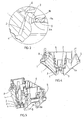
- the interlocking for quick connection key used in electrical mechanisms such as switches, push buttons, cross-over switches, plug outlets and such like, consists of an appendage -2-, situated at the lower end of the quick connection key -1-, which finishes in a hook -3-, projecting inwards, this appendage -2- being joined to the quick connection key -1- by an area -4-, which offers flexibility to said joint and permits that the entire appendage -2- can move towards the body of the quick connection key -1- when it is pressed or on its hook -3-, returning to its starting position at the time when this pressure stops being applied.
- the quick connection key -1- is placed on the U-shaped housing -5- of the body -6- of the mechanism on both sides.
- the housing of the side is visible where the quick connection key -1- is not placed, while the key -1- hides the housing where it is placed and whereon it swings freely, although the axis of rotation - 7- of the quick connection key -1- is indicated with tracing lines in its swinging movement.
- the hollow -8- of the upper part of the quick connection key -1- can also be observed in the different figures, where the end of the wire to be connected (not drawn) is inserted, hollow which changes position as the key -1- swings on the aforementioned axis -7-, getting closer to the external lateral face -6a- of the body -6-, as can be observed in figures 2 and 4 , and which causes the retention of the wire for its connection.
- the hook -3- of the appendage -2- which constitutes the interlocking, between the lower face -2a- of said appendage and the upper face -9b- of the lower projection-9-, is unclipped from the upper edge -9b- of the projection-9-, thanks to the elasticity of the material with which the entire quick connection key -1- has been constructed.
- said key -1- will be able to swing again and separate itself from the side -6a- of the body -6- with the aim of removing the wire which could be connected or placing one for its connection.
Landscapes
- Physics & Mathematics (AREA)
- Electromagnetism (AREA)
- Details Of Connecting Devices For Male And Female Coupling (AREA)
- Clamps And Clips (AREA)
- Switch Cases, Indication, And Locking (AREA)
- Lock And Its Accessories (AREA)
- Supports Or Holders For Household Use (AREA)
Applications Claiming Priority (1)
| Application Number | Priority Date | Filing Date | Title |
|---|---|---|---|
| ES200800951U ES1067865Y (es) | 2008-05-07 | 2008-05-07 | Enclavamiento para tecla de embornado rapido en mecanismos electricos |
Publications (2)
| Publication Number | Publication Date |
|---|---|
| EP2117023A2 true EP2117023A2 (fr) | 2009-11-11 |
| EP2117023A3 EP2117023A3 (fr) | 2012-01-04 |
Family
ID=39514731
Family Applications (1)
| Application Number | Title | Priority Date | Filing Date |
|---|---|---|---|
| EP09380066A Withdrawn EP2117023A3 (fr) | 2008-05-07 | 2009-04-01 | Inter-verrouillage pour une touche de connexion rapide dans des mécanismes électriques |
Country Status (5)
| Country | Link |
|---|---|
| EP (1) | EP2117023A3 (fr) |
| CN (1) | CN101578024A (fr) |
| ES (1) | ES1067865Y (fr) |
| MA (1) | MA31277B1 (fr) |
| RU (1) | RU2516231C2 (fr) |
Cited By (1)
| Publication number | Priority date | Publication date | Assignee | Title |
|---|---|---|---|---|
| EP3687007A1 (fr) * | 2019-01-23 | 2020-07-29 | Gira Giersiepen GmbH & Co. Kg | Partie socle à levier de libération |
Families Citing this family (2)
| Publication number | Priority date | Publication date | Assignee | Title |
|---|---|---|---|---|
| ES1069768Y (es) * | 2008-10-07 | 2009-08-21 | Simon Sa | Tecla de embornado rapido para mecanismos electricos con enclavamiento de seguridad |
| CN106165207B (zh) * | 2014-02-06 | 2019-11-15 | 富加宜(亚洲)私人有限公司 | 连接器组件 |
Citations (7)
| Publication number | Priority date | Publication date | Assignee | Title |
|---|---|---|---|---|
| GB2114824A (en) * | 1982-02-10 | 1983-08-24 | Woertz Oskar | Electrical terminal |
| FR2730096A1 (fr) * | 1995-01-30 | 1996-08-02 | Seifel Sa | Dispositif de connexion pour constituer un noeud d'un reseau numerique, tel qu'un reseau de releve de compteurs electriques |
| EP0936697A1 (fr) * | 1998-02-17 | 1999-08-18 | Weidmüller Interface GmbH & Co. | Reglette avec bornes à déplacement d'isolant |
| US6139352A (en) * | 1998-12-21 | 2000-10-31 | Lucent Technologies Inc. | Insulation displacement connector with selectively removable abutment wall |
| US6174179B1 (en) * | 1998-04-17 | 2001-01-16 | Yazaki Corporation | Lever engagement connector having engaging and disengaging fulcrums |
| US6264495B1 (en) * | 1999-02-02 | 2001-07-24 | The Whitaker Corporation | Electrical components |
| US6296515B1 (en) * | 2000-02-29 | 2001-10-02 | Avaya Technology Corp. | Connector having a latching mechanism |
Family Cites Families (1)
| Publication number | Priority date | Publication date | Assignee | Title |
|---|---|---|---|---|
| RU2001135118A (ru) * | 2001-12-20 | 2003-08-10 | Алексей Степанович Подольский | Электрический двухклавишный выключатель тумблерного типа |
-
2008
- 2008-05-07 ES ES200800951U patent/ES1067865Y/es not_active Expired - Fee Related
-
2009
- 2009-04-01 EP EP09380066A patent/EP2117023A3/fr not_active Withdrawn
- 2009-04-28 MA MA31826A patent/MA31277B1/fr unknown
- 2009-04-29 RU RU2009116191/07A patent/RU2516231C2/ru not_active IP Right Cessation
- 2009-05-06 CN CNA2009101371737A patent/CN101578024A/zh active Pending
Patent Citations (7)
| Publication number | Priority date | Publication date | Assignee | Title |
|---|---|---|---|---|
| GB2114824A (en) * | 1982-02-10 | 1983-08-24 | Woertz Oskar | Electrical terminal |
| FR2730096A1 (fr) * | 1995-01-30 | 1996-08-02 | Seifel Sa | Dispositif de connexion pour constituer un noeud d'un reseau numerique, tel qu'un reseau de releve de compteurs electriques |
| EP0936697A1 (fr) * | 1998-02-17 | 1999-08-18 | Weidmüller Interface GmbH & Co. | Reglette avec bornes à déplacement d'isolant |
| US6174179B1 (en) * | 1998-04-17 | 2001-01-16 | Yazaki Corporation | Lever engagement connector having engaging and disengaging fulcrums |
| US6139352A (en) * | 1998-12-21 | 2000-10-31 | Lucent Technologies Inc. | Insulation displacement connector with selectively removable abutment wall |
| US6264495B1 (en) * | 1999-02-02 | 2001-07-24 | The Whitaker Corporation | Electrical components |
| US6296515B1 (en) * | 2000-02-29 | 2001-10-02 | Avaya Technology Corp. | Connector having a latching mechanism |
Cited By (1)
| Publication number | Priority date | Publication date | Assignee | Title |
|---|---|---|---|---|
| EP3687007A1 (fr) * | 2019-01-23 | 2020-07-29 | Gira Giersiepen GmbH & Co. Kg | Partie socle à levier de libération |
Also Published As
| Publication number | Publication date |
|---|---|
| RU2516231C2 (ru) | 2014-05-20 |
| EP2117023A3 (fr) | 2012-01-04 |
| MA31277B1 (fr) | 2010-04-01 |
| RU2009116191A (ru) | 2010-11-10 |
| ES1067865U (es) | 2008-07-01 |
| CN101578024A (zh) | 2009-11-11 |
| ES1067865Y (es) | 2008-10-01 |
Similar Documents
| Publication | Publication Date | Title |
|---|---|---|
| EP2947718B1 (fr) | Borne de connexion de serrage à ressort | |
| US5711684A (en) | Connector housing locking mechanism | |
| TWI307980B (en) | Electrical connector | |
| CN108063065B (zh) | 开关装置的锁扣结构 | |
| EP2117023A2 (fr) | Inter-verrouillage pour une touche de connexion rapide dans des mécanismes électriques | |
| JPH07307184A (ja) | ラッチ式電気コネクタ | |
| CZ376896A3 (en) | Device for automatic attachment or closing and the use thereof | |
| JPH0636251U (ja) | コネクタの解除感知機構 | |
| CN107750409B (zh) | 用于附装壳体的保护帽 | |
| WO2014151997A1 (fr) | Ensemble connecteur et procédé d'utilisation | |
| AU2014272971A1 (en) | Electrical connection system with automatic closing | |
| AU2024204754A1 (en) | Connection system and method for electrical outlets | |
| KR100301878B1 (ko) | 소형푸쉬버튼스위치 | |
| JP4625398B2 (ja) | 固定機構 | |
| JP2017191717A (ja) | 回路遮断器 | |
| SE520615C2 (sv) | Kopplingsdon för en grenanslutning till en huvudledning | |
| EP2180549A1 (fr) | Clé de connexion rapide pour mécanismes électriques avec un interverrouillage de sécurité | |
| KR20110017261A (ko) | 박스의 커버결합장치 | |
| JPH05234624A (ja) | 電線接続装置 | |
| KR101702430B1 (ko) | 플렉시블 케이블용 커넥터 | |
| JPH0735177Y2 (ja) | 長尺体固定用クランプ | |
| AU2017101930A4 (en) | Improvements in an electrical module connector and system | |
| KR20140083826A (ko) | 커넥터 | |
| KR920704382A (ko) | 커버 디바이스 및 이와 함께 사용된 케이블 | |
| KR20100009733U (ko) | 박스의 고정장치 |
Legal Events
| Date | Code | Title | Description |
|---|---|---|---|
| PUAI | Public reference made under article 153(3) epc to a published international application that has entered the european phase |
Free format text: ORIGINAL CODE: 0009012 |
|
| AK | Designated contracting states |
Kind code of ref document: A2 Designated state(s): AT BE BG CH CY CZ DE DK EE ES FI FR GB GR HR HU IE IS IT LI LT LU LV MC MK MT NL NO PL PT RO SE SI SK TR |
|
| 17P | Request for examination filed |
Effective date: 20091028 |
|
| PUAL | Search report despatched |
Free format text: ORIGINAL CODE: 0009013 |
|
| AK | Designated contracting states |
Kind code of ref document: A3 Designated state(s): AT BE BG CH CY CZ DE DK EE ES FI FR GB GR HR HU IE IS IT LI LT LU LV MC MK MT NL NO PL PT RO SE SI SK TR |
|
| AX | Request for extension of the european patent |
Extension state: AL BA RS |
|
| RIC1 | Information provided on ipc code assigned before grant |
Ipc: H01R 4/24 20060101ALI20111128BHEP Ipc: H01H 1/58 20060101AFI20111128BHEP |
|
| STAA | Information on the status of an ep patent application or granted ep patent |
Free format text: STATUS: THE APPLICATION HAS BEEN WITHDRAWN |
|
| 18W | Application withdrawn |
Effective date: 20121001 |