EP2117019B1 - Modular device for clamping and positioning power transformer windings, particularly for a dry-type transformer with resin-encapsulated windings - Google Patents
Modular device for clamping and positioning power transformer windings, particularly for a dry-type transformer with resin-encapsulated windings Download PDFInfo
- Publication number
- EP2117019B1 EP2117019B1 EP08425162.8A EP08425162A EP2117019B1 EP 2117019 B1 EP2117019 B1 EP 2117019B1 EP 08425162 A EP08425162 A EP 08425162A EP 2117019 B1 EP2117019 B1 EP 2117019B1
- Authority
- EP
- European Patent Office
- Prior art keywords
- block
- windings
- base block
- modular device
- sides
- Prior art date
- Legal status (The legal status is an assumption and is not a legal conclusion. Google has not performed a legal analysis and makes no representation as to the accuracy of the status listed.)
- Active
Links
- 238000004804 winding Methods 0.000 title claims description 56
- 230000013011 mating Effects 0.000 claims 3
- 238000003825 pressing Methods 0.000 description 6
- 238000009413 insulation Methods 0.000 description 5
- 238000009423 ventilation Methods 0.000 description 4
- 150000001875 compounds Chemical class 0.000 description 2
- 238000004519 manufacturing process Methods 0.000 description 2
- 230000000717 retained effect Effects 0.000 description 2
- 125000006850 spacer group Chemical group 0.000 description 2
- 238000004026 adhesive bonding Methods 0.000 description 1
- 238000005273 aeration Methods 0.000 description 1
- 239000011449 brick Substances 0.000 description 1
- 230000000295 complement effect Effects 0.000 description 1
- 230000008878 coupling Effects 0.000 description 1
- 238000010168 coupling process Methods 0.000 description 1
- 238000005859 coupling reaction Methods 0.000 description 1
- 238000013016 damping Methods 0.000 description 1
- 238000006073 displacement reaction Methods 0.000 description 1
- 238000009826 distribution Methods 0.000 description 1
- 230000005520 electrodynamics Effects 0.000 description 1
- 230000005284 excitation Effects 0.000 description 1
- 238000001746 injection moulding Methods 0.000 description 1
- 238000003780 insertion Methods 0.000 description 1
- 230000037431 insertion Effects 0.000 description 1
- 239000011810 insulating material Substances 0.000 description 1
- 230000014759 maintenance of location Effects 0.000 description 1
- 239000000463 material Substances 0.000 description 1
- 238000000034 method Methods 0.000 description 1
- 239000004033 plastic Substances 0.000 description 1
- 230000003014 reinforcing effect Effects 0.000 description 1
- KKEYFWRCBNTPAC-UHFFFAOYSA-L terephthalate(2-) Chemical compound [O-]C(=O)C1=CC=C(C([O-])=O)C=C1 KKEYFWRCBNTPAC-UHFFFAOYSA-L 0.000 description 1
Images

Classifications
-
- H—ELECTRICITY
- H01—ELECTRIC ELEMENTS
- H01F—MAGNETS; INDUCTANCES; TRANSFORMERS; SELECTION OF MATERIALS FOR THEIR MAGNETIC PROPERTIES
- H01F27/00—Details of transformers or inductances, in general
- H01F27/28—Coils; Windings; Conductive connections
- H01F27/30—Fastening or clamping coils, windings, or parts thereof together; Fastening or mounting coils or windings on core, casing, or other support
- H01F27/306—Fastening or mounting coils or windings on core, casing or other support
-
- H—ELECTRICITY
- H01—ELECTRIC ELEMENTS
- H01F—MAGNETS; INDUCTANCES; TRANSFORMERS; SELECTION OF MATERIALS FOR THEIR MAGNETIC PROPERTIES
- H01F27/00—Details of transformers or inductances, in general
- H01F27/28—Coils; Windings; Conductive connections
- H01F27/32—Insulating of coils, windings, or parts thereof
- H01F27/327—Encapsulating or impregnating
- H01F2027/328—Dry-type transformer with encapsulated foil winding, e.g. windings coaxially arranged on core legs with spacers for cooling and with three phases
Definitions
- the present invention relates to a modular device for clamping and positioning power transformer windings, particularly for dry-type transformers with resin-encapsulated windings.
- Power transformers are known to be generally formed of a sheet pack (magnet core) with two yokes clamped by yoke pressing plates and two or three columns.
- Low and high voltage windings are concentrically arranged around the columns, the low voltage windings being interposed between the columns and the high voltage windings.
- clamping devices shall have a certain controlled elasticity to absorb the different thermal expansion of the windings during operation and to damp vibrations, which will thence not be transferred to the whole structure.
- clamping devices are generally employed which are specially designed to fit the size of the transformer and its windings, which size can be varied over wide ranges and involves highly variable insulation spacings and sizes of the clamping devices.
- DE 20105608U which is regarded as the closest prior art
- DE 20210882U disclose modular clamping devices, composed of a combination of different elements of insulating material.
- Such spacers may also be used as transformer windings clamping devices, but are unsuitable to cope with the requirements imposed by the overall diameter of the concentric windings, which varies in a relatively wide range.
- the present invention solves this problem and provides a modular sturdy system to form clamping devices that use, possibly multiple times, distinct elements that can be stacked and assembled like the bricks of the well-known LEGO (registered trademark) toy.
- the system substantially comprises an elongate base block or support, a second substantially square element, that can be defined as a bolt holder, but also acts as a rubber pad holding element and as a support shim for a winding and a third element, similar to the second, that can be defined as a winding guide or centering element, which also acts as a rubber pad-holder and support shim for a winding.
- the invention addresses the issue of providing clamping devices with a minimized number of different parts and the required rubber pads, that can fit transformers in which the diameter of the concentric windings varies in a relatively wide range and, by repeated use of the same part type, provide all the thicknesses required to ensure the required voltage-related insulation spacing and to allow the device to accommodate windings having different axial dimensions.
- the particular conformation of the elements ensures a high surface electric resistance and does not affect the efficiency of the ventilation passages typically interposed between the primary and secondary windings, thanks to the provision of air flow passageways in the base block.
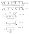
- the base block 1 is a hollow rectangular parallelepiped element having a length K (e.g. 140 mm), a width W1 (e.g. 55 mm) and a thickness H1 (e.g. 18 mm), conveniently beveled at one end
- the block 1 is formed by injection molding of a plastic material having high mechanical and dielectric strength, such as PBT (polybutilen terephthalate) and has two sides 2, 3 interconnected by a plurality of transverse ribs, such as the rib 4, which have either a vertical extension as shown in the sectional view of Figure 8 or are inclined to the vertical at least in the central part of the block, for reasons to be explained hereafter, as shown in Figure 9 .
- PBT polybutilen terephthalate
- the block structure is further reinforced by a pair of ribs 5, 6 extending parallel to the sides 2, 3.
- the sides 2, 3 have a continuous upper toothing 7, 8, conveniently recessed (e.g. by 2.5 mm) relative to the lower part, which preferably has a triangular shape, tapered at its top, with a pitch of the order of 2 ⁇ 3 mm and a height H3 of the order of 3 mm.
- the distance between the toothing crests of the two opposed toothings 7, 8 is W2 (approximately equal to W1 - 7 mm, i.e. in this example 48 mm).
- the sides 2, 3 extend downwards further than the connecting and reinforcing ribs, to form a continuous housing, open at its ends, with a depth H3 equal to the height of the toothings 7, 8.
- this housing also have toothings 9, 10 identical to the toothings 7, 8.
- the distances between the troughs of the two opposed toothings 9, 10 is equal to W2.
- the base block has identical upper and lower transverse interlocking profiles.
- the bolt holding element 11 is also a parallelepipedal block, having substantially square top and bottom faces and a width exactly equal to the width W1 of the base block.
- the height H2 of the parallelepiped may be equal (18 mm) to or conveniently lower (e.g. 15 mm) than that of the base block.
- the bolt holding block also has identical upper and lower transverse profiles, which are also identical to those of the base element, with two sides 12, 13 having an upper external toothing 14, 15, which is also identical to that of the sides of the base element.
- sides 12, 13 extend downwards to form a housing open at its ends, with toothed sides, having the same transverse dimension W2 and depth H3 as the upper profile of the base block and of the bolt holding element itself.
- the bolt holding block has a closed bottom 16 and stiffening ribs 17 that form a hexagonal prismatic housing 18, open at its top face, for accommodating the head of a clamping bolt commonly used in transformers for exerting an adequate and controlled pressure on the windings.
- the closed bottom 16 not only provides a support for the clamping bolt head but also helps in stiffening the element.
- the bolt holder may be coupled to the base block in the most appropriate position for clamping.
- the guide element has a ribbed flap 20 at one end, which extends from the bottom 21 of the lower housing, perpendicular to the latter.
- the various elements may be used on either the upper or lower side of the windings and may be also mounted in the transformer in reverse or upturned positions.
- Clamping of windings requires the provision of resilient members for damping vibrations (generated by alternate excitation of windings) and absorbing the thermal expansions that occur during operation.
- these resilient members are rubber pads glued to the clamping devices and interposed between the latter and the windings.
- the housings formed in the lower side of the bolt holding block and the guide element act as receptacles for positioning and stable retention of resilient pads having a transverse dimension L1 slightly larger than the width W2 of the housings.
- One of these pads substantially having the shape of a rectangular parallelepiped, and a thickness related to the requested elastic constant is shown in Figure 7 and designated by numeral 22.
- the dashed arrow 23 indicates the direction of insertion of the pad 22 into the guide element 19 of Figure 6 , although it will be understood that the same pad may be inserted in the lower housing of the bolt holding block (see Fig. 4 ), which is used in this case as a simple rubber pad holding block or, if needed, may be also inserted in the lower housing of the base block 1.
- the continuous and uniform section of the pad allows it to be obtained from a cut-to-size extruded strip, thereby simplifying the manufacturing process.
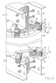
- Figure 13 shows a partial perspective view of an embodiment of the above elements that are used for forming compound devices for clamping the windings of a transformer, with the windings being arranged coaxial with the columns of the magnet core.
- Figure 13 shows that the upper and lower yokes of the transformer are respectively clamped by a magnet keeper that is formed, as is known, of a pair of yoke-pressing plates consisting of beams or C-sections 24, 25 and 26, 27 connected together by tie rods.
- the angle bars 28, 29 of the lower yoke-pressing plates act as supports for a plurality of (generally four per column) clamping devices (only two of them 30, 31 being shown herein) evenly distributed around the columns and radially oriented relative to the axis of the columns.
- angle bars 32, 33 of the upper yoke-pressing plates act as retainers for a plurality of (generally four per column) pressing bolts (only two of them 34, 35 being shown herein) which exert a convenient force upon corresponding clamping devices 36, 37 placed above the windings.
- Figure 13 shows an external medium/high voltage primary winding 38 in the transformer and an internal low voltage secondary winding formed of two coaxial windings 39, 40.
- the low voltage windings 39, 40 have a larger axial size than the medium/high voltage winding.
- the upper clamping device 37 (and the device 36) is composed of the following elements, from top to bottom:
- the lower clamping device 31 (and the device 30) is composed (from bottom to top) of the following elements, disposed in a reverse direction with respect to those used in the previous figures:
- the bolt holder and the guide element are thinner than the base element, then the difference will be very small (such as 3 mm) and may be eliminated, if needed, by replacing, in the lower clamping device, the base block 51 with two bolt holding blocks interposed between the base block 50 and the pad 52 on the one hand and between the base block 50 and the guide element 53 on the other.
- the base block 48 may be replaced by a bolt holder to be laid on the angle bar 28.
- the first alternative is preferable for stability reasons.
- the bolt holder 41 should be placed in a radially intermediate position between the two windings.
- the present device may be used with windings whose radial dimension is larger than the length of the base blocks.
- the base block/s can simply have a pair of bolt holding elements coupled thereto, partially stacked above the base block and projecting out of its ends, as allowed by the interlocking toothing, with the only condition that the stress center is contained in the base block.
- a bolt holding block may be seamlessly coupled to a bolt holding block, the pair being retained by a base block in stacked relationship to both (like in the shift joints technique used in masonry).
Landscapes
- Engineering & Computer Science (AREA)
- Power Engineering (AREA)
- Housings And Mounting Of Transformers (AREA)
- Coils Or Transformers For Communication (AREA)
Description
- The present invention relates to a modular device for clamping and positioning power transformer windings, particularly for dry-type transformers with resin-encapsulated windings.
- Power transformers are known to be generally formed of a sheet pack (magnet core) with two yokes clamped by yoke pressing plates and two or three columns.
- Low and high voltage windings are concentrically arranged around the columns, the low voltage windings being interposed between the columns and the high voltage windings.
- Accurate and stable positioning of low and high voltage windings, spaced from each other and the magnet core (yokes and columns) as prescribed in the design specifications are required to meet a number of needs: on the one hand, the windings should be mechanically clamped to avoid excessive vibrations thereupon during operation of the transformer or, even worse, displacements caused by electrodynamic stresses generated in load conditions, particularly at full load or in case of a short circuit; on the other hand, electric insulation of the windings from each other, the core and any other part of the transformer at ground potential should be ensured, while allowing proper aeration in the ventilation passages formed between or within the windings (particularly the low voltage winding, having high currents therein).
- Furthermore, the clamping devices shall have a certain controlled elasticity to absorb the different thermal expansion of the windings during operation and to damp vibrations, which will thence not be transferred to the whole structure.
- In view of fulfilling the above requirements, clamping devices are generally employed which are specially designed to fit the size of the transformer and its windings, which size can be varied over wide ranges and involves highly variable insulation spacings and sizes of the clamping devices.
- This implies high costs for manufacturing and stock management.
- In an attempt to at least partially obviate the above drawbacks,
DE 20105608U , which is regarded as the closest prior art, andDE 20210882U disclose modular clamping devices, composed of a combination of different elements of insulating material. - Nonetheless, no provision is made therein to stacked coupling of elements of the same type.
- Also, the adaptability of these modular devices to various needs is limited and requires the provision of elements of different thicknesses.
- In view of obviating this limitation, compound clamping devices have been proposed, as disclosed in
EP1298681 , in which two of the multiple elements that compose the device may be interlocked together to obtain different combined thicknesses. - These devices have a particularly complex structure and provide little mechanical strength and adaptability to the required wide range of thicknesses.
- Another approach is proposed by
GB1,115,025 - Such spacers may also be used as transformer windings clamping devices, but are unsuitable to cope with the requirements imposed by the overall diameter of the concentric windings, which varies in a relatively wide range.
- The present invention solves this problem and provides a modular sturdy system to form clamping devices that use, possibly multiple times, distinct elements that can be stacked and assembled like the bricks of the well-known LEGO (registered trademark) toy.
- The system substantially comprises an elongate base block or support, a second substantially square element, that can be defined as a bolt holder, but also acts as a rubber pad holding element and as a support shim for a winding and a third element, similar to the second, that can be defined as a winding guide or centering element, which also acts as a rubber pad-holder and support shim for a winding.
- The invention, as characterized by the claims, addresses the issue of providing clamping devices with a minimized number of different parts and the required rubber pads, that can fit transformers in which the diameter of the concentric windings varies in a relatively wide range and, by repeated use of the same part type, provide all the thicknesses required to ensure the required voltage-related insulation spacing and to allow the device to accommodate windings having different axial dimensions.
- Furthermore, the particular conformation of the elements ensures a high surface electric resistance and does not affect the efficiency of the ventilation passages typically interposed between the primary and secondary windings, thanks to the provision of air flow passageways in the base block.
- The characteristics and advantage of the invention will be more apparent from the following description of a preferred embodiment, when taken with reference to the accompanying drawings, in which
-
Figure 1 is a perspective top view of a preferred embodiment of a base block for the modular clamping device of the present invention; -
Figure 2 is a perspective bottom view of the base block ofFigure 1 ; -
Figure 3 is a perspective top view of a bolt holding element for the modular clamping device of the present invention; -
Figure 4 is a perspective bottom view of the bolt-holding element ofFigure 3 ; -
Figure 5 is a perspective top view of a preferred embodiment of a centering element for the modular clamping device of the present invention; -
Figure 6 is a perspective bottom view of the guide element ofFigure 5 ; -
Figure 7 is a perspective view of a resilient pad for the modular clamping device of the present invention; -
Figure 8 is a longitudinal sectional view of the base block ofFigure 1 , as taken along the line A-A ofFigure 1 ; -
Figure 9 is a longitudinal sectional view of a variant embodiment of the base block ofFigure 1 , as taken along the line A-A ofFigure 1 ; -
Figure 10 is a front view of the base block ofFigures 1, 2 ,8 and 9 ; -
Figure 11 is a front view of the bolt-holding element ofFigures 3 and 4 ; -
Figure 12 is a front view of the guide or centering element ofFigures 5 and 6 ; -
Figure 13 is a partial perspective view of a transformer incorporating an embodiment of the clamping device of the present invention. - Referring to
Figures 1, 2 ,8, 9 and 10 thebase block 1 is a hollow rectangular parallelepiped element having a length K (e.g. 140 mm), a width W1 (e.g. 55 mm) and a thickness H1 (e.g. 18 mm), conveniently beveled at one end - The
block 1 is formed by injection molding of a plastic material having high mechanical and dielectric strength, such as PBT (polybutilen terephthalate) and has twosides Figure 8 or are inclined to the vertical at least in the central part of the block, for reasons to be explained hereafter, as shown inFigure 9 . - The block structure is further reinforced by a pair of ribs 5, 6 extending parallel to the
sides - The
sides upper toothing - The distance between the toothing crests of the two opposed
toothings - As clearly shown in
Figures 2 and10 , thesides toothings - As clearly shown in
Figure 2 and inFigure 8 , the sides of this housing also havetoothings toothings - The distances between the troughs of the two opposed
toothings - In other words, the base block has identical upper and lower transverse interlocking profiles.
- These profiles allow stable interlock of multiple base blocks in stacked relationship, possibly with a longitudinal stagger that is equal to or a multiple of the tooth pitch (2 ÷ 3 mm).
- Thus, different thicknesses may be obtained, equal to H1 + N.(H1 - H3) where N is zero or a positive integer, by way of example with a 15 mm resolution.
- Referring to
Figures 3, 4 , thebolt holding element 11 is also a parallelepipedal block, having substantially square top and bottom faces and a width exactly equal to the width W1 of the base block. - The height H2 of the parallelepiped may be equal (18 mm) to or conveniently lower (e.g. 15 mm) than that of the base block.
- The bolt holding block also has identical upper and lower transverse profiles, which are also identical to those of the base element, with two
sides external toothing - Also the
sides - This allows stable interlocking of multiple blocks in stacked relationship to each other or to one or more base blocks to obtain different combined thicknesses with a resolution depending on the combined thicknesses of the base block and the bolt holding block, if different.
- Concerning the specific use of the bolt holding block, the latter has a closed
bottom 16 andstiffening ribs 17 that form a hexagonalprismatic housing 18, open at its top face, for accommodating the head of a clamping bolt commonly used in transformers for exerting an adequate and controlled pressure on the windings. - The closed
bottom 16 not only provides a support for the clamping bolt head but also helps in stiffening the element. - By its lateral interlocking toothings, the bolt holder may be coupled to the base block in the most appropriate position for clamping.
- The structure and the size of the guide or centering
element 19 as shown in the perspective views ofFigures 5, 6 and in the front view ofFigure 12 are similar, when not even identical to those of the bolt holding block. - The only difference is that the guide element has a ribbed
flap 20 at one end, which extends from thebottom 21 of the lower housing, perpendicular to the latter. - It shall be noted that, as used herein, the terms upper and lower, top and bottom are related to the viewing directions of the figures.
- Indeed, the various elements may be used on either the upper or lower side of the windings and may be also mounted in the transformer in reverse or upturned positions.
- The difference involved in these applications is that a use on the lower side of the windings does not generally require a bolt-holding block with this specific function, although it doesn't exclude it, because the base block can simply lie on the support structure, with its top face (see
Fig. 1 ) facing towards the support structure. - This aspect will be further explained below.
- First a further feature of both the
guide element 19 and the bolt holding block has to be considered. - Clamping of windings requires the provision of resilient members for damping vibrations (generated by alternate excitation of windings) and absorbing the thermal expansions that occur during operation.
- As a rule, these resilient members are rubber pads glued to the clamping devices and interposed between the latter and the windings.
- With a modular device as disclosed above no gluing is required: the housings formed in the lower side of the bolt holding block and the guide element act as receptacles for positioning and stable retention of resilient pads having a transverse dimension L1 slightly larger than the width W2 of the housings.
- One of these pads, substantially having the shape of a rectangular parallelepiped, and a thickness related to the requested elastic constant is shown in
Figure 7 and designated bynumeral 22. - The dashed arrow 23 indicates the direction of insertion of the
pad 22 into theguide element 19 ofFigure 6 , although it will be understood that the same pad may be inserted in the lower housing of the bolt holding block (seeFig. 4 ), which is used in this case as a simple rubber pad holding block or, if needed, may be also inserted in the lower housing of thebase block 1. - It shall be further noted that the continuous and uniform section of the pad allows it to be obtained from a cut-to-size extruded strip, thereby simplifying the manufacturing process.
- For better clarity,
Figure 13 shows a partial perspective view of an embodiment of the above elements that are used for forming compound devices for clamping the windings of a transformer, with the windings being arranged coaxial with the columns of the magnet core. -
Figure 13 shows that the upper and lower yokes of the transformer are respectively clamped by a magnet keeper that is formed, as is known, of a pair of yoke-pressing plates consisting of beams or C-sections - The angle bars 28, 29 of the lower yoke-pressing plates act as supports for a plurality of (generally four per column) clamping devices (only two of them 30, 31 being shown herein) evenly distributed around the columns and radially oriented relative to the axis of the columns.
- Likewise, the angle bars 32, 33 of the upper yoke-pressing plates act as retainers for a plurality of (generally four per column) pressing bolts (only two of them 34, 35 being shown herein) which exert a convenient force upon corresponding
clamping devices - As an example,
Figure 13 shows an external medium/high voltage primary winding 38 in the transformer and an internal low voltage secondary winding formed of twocoaxial windings - It shall be noted that the
low voltage windings - In order that the windings can be properly positioned and retained the upper clamping device 37 (and the device 36) is composed of the following elements, from top to bottom:
- a
bolt holding block 41, - a series of three base blocks 42, 43, 44 in stacked relationship,
- a resilient pad 45 held under the
base block 44 in such position as to press against the upper end of thewindings - a
guide centering element 46 placed under thebase block 44, having a flap 20 (seeFigs. 5, 6 ,12 ) that ensures proper axial arrangement of the winding 38, - a
resilient pad 47 held under theguide element 46 and pressing against the top of the winding 38. - The lower clamping device 31 (and the device 30) is composed (from bottom to top) of the following elements, disposed in a reverse direction with respect to those used in the previous figures:
- a series of four base blocks 48, 49, 50, 51 in stacked relationship, the first lying directly on the
angle bar 29, - a resilient pad 52 held on the base block 52 in such position as to support the two
low voltage windings - a
guide element 53 stacked above thebase block 51 in such position as to guide the medium/high voltage winding 38; - a
resilient pad 54 stacked above theguide element 53 to elastically support the winding 38. -
Figure 13 highlights other important aspects: - I) the insulation spacing ensured by the upper and lower clamping devices relative to the
support magnet keepers - If the bolt holder and the guide element are thinner than the base element, then the difference will be very small (such as 3 mm) and may be eliminated, if needed, by replacing, in the lower clamping device, the
base block 51 with two bolt holding blocks interposed between thebase block 50 and the pad 52 on the one hand and between thebase block 50 and theguide element 53 on the other. - Otherwise, the
base block 48 may be replaced by a bolt holder to be laid on theangle bar 28. - The first alternative is preferable for stability reasons.
- II) For stable clamping, with an even distribution of the force exerted by the
bolt 35 on both the primary and secondary windings, thebolt holder 41 should be placed in a radially intermediate position between the two windings. - Since the bolt holder and the resilient pads are impervious, this arrangement partially obstructs the ventilation passage between the two windings.
- The same applies for the lower clamping device, where air flow is obstructed by the
angle bar 29. - Nonetheless, by providing base blocks with slanted ribs, as shown in the sectional view of
Figure 9 , oblique passageways may be created in the stacked base blocks, allowing air flows through the paths designated by the dashed arrows 56, 56, which improve ventilation efficiency. - III) The slant of the ribs provides an additional advantage in terms of the surface electric resistance of the clamping devices.
- Considering the front views of
Figures 10, 11, 12 and the sectional view ofFigure 8 , it is evident that the stacked elements create a corrugated outer surface with a square wave profile. - This inherently involves an increase of the surface resistance of the device, because it increases the length of the path to be followed by any surface discharges, at least on the outer surface of the device.
- This does not apply to the ribs 4 of the base blocks as shown in the sectional view of
Figure 8 , which, when stacked, are in contact and continuation with each other. - However, an inclined arrangement like the one of
Figure 9 stops this continuity and ensures a more effective insulation in terms of surface resistance. - It will be appreciated that the same concept applies to the longitudinal ribs 5, 6 (see
Figs. 1 and 2 ), whereas a step may be provided on thesides - IV) In
Figure 13 , the radial dimension of the windings is substantially equal to the length of the base blocks. - Nonetheless, it shall be understood that nothing prevents the use of the above described device with windings of smaller radial size, in which case the base blocks project out of the outer cylindrical surface of the outermost winding.
- Likewise, the present device may be used with windings whose radial dimension is larger than the length of the base blocks.
- For this purpose, the base block/s can simply have a pair of bolt holding elements coupled thereto, partially stacked above the base block and projecting out of its ends, as allowed by the interlocking toothing, with the only condition that the stress center is contained in the base block.
- Furthermore, if the various elements have the same thickness and two or more blocks are used in stacked relationship, a bolt holding block may be seamlessly coupled to a bolt holding block, the pair being retained by a base block in stacked relationship to both (like in the shift joints technique used in masonry).
- In practice, if the length of the base block is 140 mm, and the bolt holding element is as long as 55, the device may be used in transformers in which the radial dimension of the windings falls in a range from 140 / √2 ≈ 100 mm and 140 + 2 . 27.5 = 195 mm.
- Nonetheless, for mechanical safety reasons, its use is preferably limited to windings having a radial dimension not larger or slightly larger than the width L of the base block, longer base blocks, e.g. as long as 170 to 200 mm, being provided for use in larger transformers.
- In this case, a series may be provided in which the three elements as described above all have an enlarged size.
Claims (8)
- A modular device for clamping the windings of a transformer, of the type in which an elongate base block (1), with two parallel sides (2, 3) is combined with other stacked elements and these sides extend downwards to form an elongate lower housing open at its ends, characterized in that
said sides have upper external toothings and lower internal toothings (7, 8, 9, 10) in mating interlocking relationship, the distance W2 between the two opposite upper toothings (7, 8) of the sides being equal to the distance W2 between the two facing lower internal toothings (9, 10) of the sides, so that the upper and lower transverse profiles of the base blocks mate with each other and a plurality of identical base blocks can be interlocked together in stacked relationship with a longitudinal stagger in the direction of their length. - A modular device as claimed in claim 1, wherein said sides (2, 3) are interconnected by transverse stiffening ribs (4) which leave apertures between the top face and the lower face of the base block for allowing air flow therethrough.
- A modular device as claimed in claim 2, wherein said transverse ribs (4) are inclined to a plane perpendicular to the top and bottom faces of said base block.
- A modular device as claimed in claim 1, 2 or 3, wherein said sides (2, 3) have a step such that the stacking together of said base blocks creates a corrugated outer surface with a square wave profile that increases the surface electric resistance of said device.
- A modular device as claimed in the preceding claims, comprising a winding guide element (19), said element having upper and lower transverse profiles in mating relationship, and identical to each other and to those of said base block, such that said guide element can be coupled by interlocking to said base block, said guide element having a winding guide flap (20).
- A modular device as claimed in the preceding claims, comprising a bolt holding block (11), said block having upper and lower transverse profiles in mating relationship, and identical to each other and to those of said base block, such that said bolt holding block can be coupled by interlocking to said base block, said bolt holding block having a housing (18) for receiving a bolt head.
- A modular device as claimed in claim 5 or 6, wherein the sides of said guide element (19) and/or said bolt holding block (11) have a step such that the stacking together of said guide element (19) and/or said bolt holding block (11) with said base block (1)creates a corrugated outer surface with a square wave profile that increases the surface electric resistance of said device.
- A modular device as claimed in the preceding claims, wherein said lower housing of said base block (1) and/or a corresponding lower housing of said guide element (19) or bolt holding block (11) accommodate a resilient pad (22) in interlocking relationship.
Priority Applications (2)
| Application Number | Priority Date | Filing Date | Title |
|---|---|---|---|
| EP08425162.8A EP2117019B1 (en) | 2008-03-17 | 2008-03-17 | Modular device for clamping and positioning power transformer windings, particularly for a dry-type transformer with resin-encapsulated windings |
| PL08425162T PL2117019T3 (en) | 2008-03-17 | 2008-03-17 | Modular device for clamping and positioning power transformer windings, particularly for a dry-type transformer with resin-encapsulated windings |
Applications Claiming Priority (1)
| Application Number | Priority Date | Filing Date | Title |
|---|---|---|---|
| EP08425162.8A EP2117019B1 (en) | 2008-03-17 | 2008-03-17 | Modular device for clamping and positioning power transformer windings, particularly for a dry-type transformer with resin-encapsulated windings |
Publications (2)
| Publication Number | Publication Date |
|---|---|
| EP2117019A1 EP2117019A1 (en) | 2009-11-11 |
| EP2117019B1 true EP2117019B1 (en) | 2014-05-07 |
Family
ID=39675373
Family Applications (1)
| Application Number | Title | Priority Date | Filing Date |
|---|---|---|---|
| EP08425162.8A Active EP2117019B1 (en) | 2008-03-17 | 2008-03-17 | Modular device for clamping and positioning power transformer windings, particularly for a dry-type transformer with resin-encapsulated windings |
Country Status (2)
| Country | Link |
|---|---|
| EP (1) | EP2117019B1 (en) |
| PL (1) | PL2117019T3 (en) |
Cited By (1)
| Publication number | Priority date | Publication date | Assignee | Title |
|---|---|---|---|---|
| CN105788831A (en) * | 2016-05-23 | 2016-07-20 | 江苏中容科技有限公司 | Dry-type transformer with combined type cushion blocks |
Families Citing this family (3)
| Publication number | Priority date | Publication date | Assignee | Title |
|---|---|---|---|---|
| ITMI20111618A1 (en) * | 2011-09-08 | 2013-03-09 | Tmc Italia S P A | PRESSING DEVICE FOR A DRY ELECTRIC TRANSFORMER ISOLATED IN RESIN |
| EP2626872A1 (en) * | 2012-02-13 | 2013-08-14 | ABB Sp.zo.o. | Transformer windings support |
| IT201800003584A1 (en) | 2018-03-15 | 2019-09-15 | Andrea Giorgio Colombo | Fastening member for a pressing device for a resin-insulated dry electrical transformer |
Family Cites Families (5)
| Publication number | Priority date | Publication date | Assignee | Title |
|---|---|---|---|---|
| GB1115025A (en) * | 1964-12-04 | 1968-05-22 | Ass Elect Ind | Improvements in or relating to winding spacing means of electrical transformers |
| DE20105608U1 (en) * | 2001-03-27 | 2001-11-08 | Siemens Ag | Support device for an electrical component in the form of a coil |
| FR2830369B1 (en) * | 2001-09-28 | 2003-12-26 | Pioch Sa | COIL HOLDER FOR TRANSFORMER AND TRANSFORMER COMPRISING SAME |
| DE20210882U1 (en) * | 2002-07-12 | 2002-10-10 | Siemens Ag | Support device for supporting at least one winding |
| DE102005030014B3 (en) * | 2005-06-17 | 2006-11-30 | Ismet Ag | Winding separating unit for transformer coil, has fixing units to position separating unit in preset axial position and fix separating unit in axial position at counter unit that is connected with coil or combinable with coil |
-
2008
- 2008-03-17 PL PL08425162T patent/PL2117019T3/en unknown
- 2008-03-17 EP EP08425162.8A patent/EP2117019B1/en active Active
Cited By (1)
| Publication number | Priority date | Publication date | Assignee | Title |
|---|---|---|---|---|
| CN105788831A (en) * | 2016-05-23 | 2016-07-20 | 江苏中容科技有限公司 | Dry-type transformer with combined type cushion blocks |
Also Published As
| Publication number | Publication date |
|---|---|
| EP2117019A1 (en) | 2009-11-11 |
| PL2117019T3 (en) | 2014-09-30 |
Similar Documents
| Publication | Publication Date | Title |
|---|---|---|
| US8795872B2 (en) | Battery cell system with interconnected frames | |
| EP2117019B1 (en) | Modular device for clamping and positioning power transformer windings, particularly for a dry-type transformer with resin-encapsulated windings | |
| JP5932247B2 (en) | Bobbin for coil device | |
| US8722225B2 (en) | Battery module including improved base plate | |
| KR100340604B1 (en) | Slot Seal Device | |
| US20170352466A1 (en) | Laminated Iron Core Structure and Transformer Including the Same | |
| KR20100082789A (en) | Transformer | |
| US4899122A (en) | Transformer, choke and the like | |
| KR910008535B1 (en) | Space block control means for dynamoelectric machine | |
| EP3790073B1 (en) | Battery pack | |
| CN213025739U (en) | Reactor iron core and iron core reactor | |
| US4348687A (en) | Clamping assembly for thyristor column | |
| US20220093315A1 (en) | Transformer | |
| KR102530721B1 (en) | Components and methods of manufacturing insulating spacers | |
| EP2395518B1 (en) | Housing for construction of air-gapped cylindrical magnetic cores for inductive components | |
| CA2716147C (en) | Two- or multiphase transformer | |
| CN220065334U (en) | Inductance bracket, inversion control equipment and inversion energy storage combination equipment | |
| KR20180122447A (en) | Thermal cell with encapsulated phase change material | |
| KR20200094423A (en) | Transformer | |
| US20220301756A1 (en) | Magnetic component | |
| EP3924657B1 (en) | Bundle of pipelines | |
| CN219096629U (en) | Wire harness fixing bracket | |
| CN214352019U (en) | Assembly jig for 5G power supply lightning protection module | |
| CN219164059U (en) | Large-span high-bearing insulating isolation mounting mechanism and mounting assembly | |
| WO2024004206A1 (en) | Trough lifting device |
Legal Events
| Date | Code | Title | Description |
|---|---|---|---|
| PUAI | Public reference made under article 153(3) epc to a published international application that has entered the european phase |
Free format text: ORIGINAL CODE: 0009012 |
|
| 17P | Request for examination filed |
Effective date: 20090114 |
|
| AK | Designated contracting states |
Kind code of ref document: A1 Designated state(s): AT BE BG CH CY CZ DE DK EE ES FI FR GB GR HR HU IE IS IT LI LT LU LV MC MT NL NO PL PT RO SE SI SK TR |
|
| AX | Request for extension of the european patent |
Extension state: AL BA MK RS |
|
| RAP1 | Party data changed (applicant data changed or rights of an application transferred) |
Owner name: BTICINO S.P.A. |
|
| AKX | Designation fees paid |
Designated state(s): AT BE BG CH CY CZ DE DK EE ES FI FR GB GR HR HU IE IS IT LI LT LU LV MC MT NL NO PL PT RO SE SI SK TR |
|
| 17Q | First examination report despatched |
Effective date: 20110713 |
|
| GRAP | Despatch of communication of intention to grant a patent |
Free format text: ORIGINAL CODE: EPIDOSNIGR1 |
|
| INTG | Intention to grant announced |
Effective date: 20131108 |
|
| GRAS | Grant fee paid |
Free format text: ORIGINAL CODE: EPIDOSNIGR3 |
|
| GRAA | (expected) grant |
Free format text: ORIGINAL CODE: 0009210 |
|
| RAP1 | Party data changed (applicant data changed or rights of an application transferred) |
Owner name: BTICINO S.P.A. |
|
| AK | Designated contracting states |
Kind code of ref document: B1 Designated state(s): AT BE BG CH CY CZ DE DK EE ES FI FR GB GR HR HU IE IS IT LI LT LU LV MC MT NL NO PL PT RO SE SI SK TR |
|
| REG | Reference to a national code |
Ref country code: GB Ref legal event code: FG4D |
|
| REG | Reference to a national code |
Ref country code: AT Ref legal event code: REF Ref document number: 667233 Country of ref document: AT Kind code of ref document: T Effective date: 20140515 |
|
| REG | Reference to a national code |
Ref country code: IE Ref legal event code: FG4D |
|
| REG | Reference to a national code |
Ref country code: NL Ref legal event code: T3 |
|
| REG | Reference to a national code |
Ref country code: DE Ref legal event code: R096 Ref document number: 602008032022 Country of ref document: DE Effective date: 20140618 |
|
| REG | Reference to a national code |
Ref country code: NO Ref legal event code: T2 Effective date: 20140507 |
|
| REG | Reference to a national code |
Ref country code: AT Ref legal event code: MK05 Ref document number: 667233 Country of ref document: AT Kind code of ref document: T Effective date: 20140507 |
|
| REG | Reference to a national code |
Ref country code: PL Ref legal event code: T3 |
|
| REG | Reference to a national code |
Ref country code: LT Ref legal event code: MG4D |
|
| PG25 | Lapsed in a contracting state [announced via postgrant information from national office to epo] |
Ref country code: LT Free format text: LAPSE BECAUSE OF FAILURE TO SUBMIT A TRANSLATION OF THE DESCRIPTION OR TO PAY THE FEE WITHIN THE PRESCRIBED TIME-LIMIT Effective date: 20140507 Ref country code: FI Free format text: LAPSE BECAUSE OF FAILURE TO SUBMIT A TRANSLATION OF THE DESCRIPTION OR TO PAY THE FEE WITHIN THE PRESCRIBED TIME-LIMIT Effective date: 20140507 Ref country code: GR Free format text: LAPSE BECAUSE OF FAILURE TO SUBMIT A TRANSLATION OF THE DESCRIPTION OR TO PAY THE FEE WITHIN THE PRESCRIBED TIME-LIMIT Effective date: 20140808 Ref country code: CY Free format text: LAPSE BECAUSE OF FAILURE TO SUBMIT A TRANSLATION OF THE DESCRIPTION OR TO PAY THE FEE WITHIN THE PRESCRIBED TIME-LIMIT Effective date: 20140507 Ref country code: IS Free format text: LAPSE BECAUSE OF FAILURE TO SUBMIT A TRANSLATION OF THE DESCRIPTION OR TO PAY THE FEE WITHIN THE PRESCRIBED TIME-LIMIT Effective date: 20140907 |
|
| PG25 | Lapsed in a contracting state [announced via postgrant information from national office to epo] |
Ref country code: LV Free format text: LAPSE BECAUSE OF FAILURE TO SUBMIT A TRANSLATION OF THE DESCRIPTION OR TO PAY THE FEE WITHIN THE PRESCRIBED TIME-LIMIT Effective date: 20140507 Ref country code: ES Free format text: LAPSE BECAUSE OF FAILURE TO SUBMIT A TRANSLATION OF THE DESCRIPTION OR TO PAY THE FEE WITHIN THE PRESCRIBED TIME-LIMIT Effective date: 20140507 Ref country code: SE Free format text: LAPSE BECAUSE OF FAILURE TO SUBMIT A TRANSLATION OF THE DESCRIPTION OR TO PAY THE FEE WITHIN THE PRESCRIBED TIME-LIMIT Effective date: 20140507 Ref country code: AT Free format text: LAPSE BECAUSE OF FAILURE TO SUBMIT A TRANSLATION OF THE DESCRIPTION OR TO PAY THE FEE WITHIN THE PRESCRIBED TIME-LIMIT Effective date: 20140507 Ref country code: HR Free format text: LAPSE BECAUSE OF FAILURE TO SUBMIT A TRANSLATION OF THE DESCRIPTION OR TO PAY THE FEE WITHIN THE PRESCRIBED TIME-LIMIT Effective date: 20140507 |
|
| PG25 | Lapsed in a contracting state [announced via postgrant information from national office to epo] |
Ref country code: PT Free format text: LAPSE BECAUSE OF FAILURE TO SUBMIT A TRANSLATION OF THE DESCRIPTION OR TO PAY THE FEE WITHIN THE PRESCRIBED TIME-LIMIT Effective date: 20140908 |
|
| PG25 | Lapsed in a contracting state [announced via postgrant information from national office to epo] |
Ref country code: BE Free format text: LAPSE BECAUSE OF FAILURE TO SUBMIT A TRANSLATION OF THE DESCRIPTION OR TO PAY THE FEE WITHIN THE PRESCRIBED TIME-LIMIT Effective date: 20140507 Ref country code: DK Free format text: LAPSE BECAUSE OF FAILURE TO SUBMIT A TRANSLATION OF THE DESCRIPTION OR TO PAY THE FEE WITHIN THE PRESCRIBED TIME-LIMIT Effective date: 20140507 Ref country code: SK Free format text: LAPSE BECAUSE OF FAILURE TO SUBMIT A TRANSLATION OF THE DESCRIPTION OR TO PAY THE FEE WITHIN THE PRESCRIBED TIME-LIMIT Effective date: 20140507 Ref country code: CZ Free format text: LAPSE BECAUSE OF FAILURE TO SUBMIT A TRANSLATION OF THE DESCRIPTION OR TO PAY THE FEE WITHIN THE PRESCRIBED TIME-LIMIT Effective date: 20140507 Ref country code: EE Free format text: LAPSE BECAUSE OF FAILURE TO SUBMIT A TRANSLATION OF THE DESCRIPTION OR TO PAY THE FEE WITHIN THE PRESCRIBED TIME-LIMIT Effective date: 20140507 Ref country code: RO Free format text: LAPSE BECAUSE OF FAILURE TO SUBMIT A TRANSLATION OF THE DESCRIPTION OR TO PAY THE FEE WITHIN THE PRESCRIBED TIME-LIMIT Effective date: 20140507 |
|
| REG | Reference to a national code |
Ref country code: DE Ref legal event code: R097 Ref document number: 602008032022 Country of ref document: DE |
|
| PLBE | No opposition filed within time limit |
Free format text: ORIGINAL CODE: 0009261 |
|
| STAA | Information on the status of an ep patent application or granted ep patent |
Free format text: STATUS: NO OPPOSITION FILED WITHIN TIME LIMIT |
|
| 26N | No opposition filed |
Effective date: 20150210 |
|
| REG | Reference to a national code |
Ref country code: DE Ref legal event code: R097 Ref document number: 602008032022 Country of ref document: DE Effective date: 20150210 |
|
| PG25 | Lapsed in a contracting state [announced via postgrant information from national office to epo] |
Ref country code: SI Free format text: LAPSE BECAUSE OF FAILURE TO SUBMIT A TRANSLATION OF THE DESCRIPTION OR TO PAY THE FEE WITHIN THE PRESCRIBED TIME-LIMIT Effective date: 20140507 |
|
| REG | Reference to a national code |
Ref country code: DE Ref legal event code: R119 Ref document number: 602008032022 Country of ref document: DE |
|
| PG25 | Lapsed in a contracting state [announced via postgrant information from national office to epo] |
Ref country code: MC Free format text: LAPSE BECAUSE OF FAILURE TO SUBMIT A TRANSLATION OF THE DESCRIPTION OR TO PAY THE FEE WITHIN THE PRESCRIBED TIME-LIMIT Effective date: 20140507 Ref country code: LU Free format text: LAPSE BECAUSE OF FAILURE TO SUBMIT A TRANSLATION OF THE DESCRIPTION OR TO PAY THE FEE WITHIN THE PRESCRIBED TIME-LIMIT Effective date: 20150317 |
|
| REG | Reference to a national code |
Ref country code: CH Ref legal event code: PL |
|
| REG | Reference to a national code |
Ref country code: IE Ref legal event code: MM4A |
|
| PG25 | Lapsed in a contracting state [announced via postgrant information from national office to epo] |
Ref country code: IE Free format text: LAPSE BECAUSE OF NON-PAYMENT OF DUE FEES Effective date: 20150317 Ref country code: CH Free format text: LAPSE BECAUSE OF NON-PAYMENT OF DUE FEES Effective date: 20150331 Ref country code: LI Free format text: LAPSE BECAUSE OF NON-PAYMENT OF DUE FEES Effective date: 20150331 Ref country code: DE Free format text: LAPSE BECAUSE OF NON-PAYMENT OF DUE FEES Effective date: 20151001 |
|
| REG | Reference to a national code |
Ref country code: FR Ref legal event code: PLFP Year of fee payment: 9 |
|
| PG25 | Lapsed in a contracting state [announced via postgrant information from national office to epo] |
Ref country code: MT Free format text: LAPSE BECAUSE OF FAILURE TO SUBMIT A TRANSLATION OF THE DESCRIPTION OR TO PAY THE FEE WITHIN THE PRESCRIBED TIME-LIMIT Effective date: 20140507 |
|
| REG | Reference to a national code |
Ref country code: FR Ref legal event code: PLFP Year of fee payment: 10 |
|
| PG25 | Lapsed in a contracting state [announced via postgrant information from national office to epo] |
Ref country code: BG Free format text: LAPSE BECAUSE OF FAILURE TO SUBMIT A TRANSLATION OF THE DESCRIPTION OR TO PAY THE FEE WITHIN THE PRESCRIBED TIME-LIMIT Effective date: 20140507 Ref country code: HU Free format text: LAPSE BECAUSE OF FAILURE TO SUBMIT A TRANSLATION OF THE DESCRIPTION OR TO PAY THE FEE WITHIN THE PRESCRIBED TIME-LIMIT; INVALID AB INITIO Effective date: 20080317 |
|
| REG | Reference to a national code |
Ref country code: FR Ref legal event code: PLFP Year of fee payment: 11 |
|
| PGFP | Annual fee paid to national office [announced via postgrant information from national office to epo] |
Ref country code: NL Payment date: 20190225 Year of fee payment: 12 |
|
| PGFP | Annual fee paid to national office [announced via postgrant information from national office to epo] |
Ref country code: NO Payment date: 20190227 Year of fee payment: 12 |
|
| PGFP | Annual fee paid to national office [announced via postgrant information from national office to epo] |
Ref country code: GB Payment date: 20200221 Year of fee payment: 13 |
|
| REG | Reference to a national code |
Ref country code: NO Ref legal event code: MMEP |
|
| REG | Reference to a national code |
Ref country code: NL Ref legal event code: MM Effective date: 20200401 |
|
| PG25 | Lapsed in a contracting state [announced via postgrant information from national office to epo] |
Ref country code: NL Free format text: LAPSE BECAUSE OF NON-PAYMENT OF DUE FEES Effective date: 20200401 |
|
| PG25 | Lapsed in a contracting state [announced via postgrant information from national office to epo] |
Ref country code: NO Free format text: LAPSE BECAUSE OF NON-PAYMENT OF DUE FEES Effective date: 20200331 |
|
| PGFP | Annual fee paid to national office [announced via postgrant information from national office to epo] |
Ref country code: TR Payment date: 20210223 Year of fee payment: 14 Ref country code: PL Payment date: 20210222 Year of fee payment: 14 |
|
| GBPC | Gb: european patent ceased through non-payment of renewal fee |
Effective date: 20210317 |
|
| PG25 | Lapsed in a contracting state [announced via postgrant information from national office to epo] |
Ref country code: GB Free format text: LAPSE BECAUSE OF NON-PAYMENT OF DUE FEES Effective date: 20210317 |
|
| PGFP | Annual fee paid to national office [announced via postgrant information from national office to epo] |
Ref country code: FR Payment date: 20220221 Year of fee payment: 15 |
|
| PGFP | Annual fee paid to national office [announced via postgrant information from national office to epo] |
Ref country code: IT Payment date: 20230221 Year of fee payment: 16 |
|
| PG25 | Lapsed in a contracting state [announced via postgrant information from national office to epo] |
Ref country code: PL Free format text: LAPSE BECAUSE OF NON-PAYMENT OF DUE FEES Effective date: 20220317 |
|
| PG25 | Lapsed in a contracting state [announced via postgrant information from national office to epo] |
Ref country code: FR Free format text: LAPSE BECAUSE OF NON-PAYMENT OF DUE FEES Effective date: 20230331 |