EP3790073B1 - Battery pack - Google Patents
Battery pack Download PDFInfo
- Publication number
- EP3790073B1 EP3790073B1 EP19769982.0A EP19769982A EP3790073B1 EP 3790073 B1 EP3790073 B1 EP 3790073B1 EP 19769982 A EP19769982 A EP 19769982A EP 3790073 B1 EP3790073 B1 EP 3790073B1
- Authority
- EP
- European Patent Office
- Prior art keywords
- battery pack
- limiting
- battery
- plates
- receiving portions
- Prior art date
- Legal status (The legal status is an assumption and is not a legal conclusion. Google has not performed a legal analysis and makes no representation as to the accuracy of the status listed.)
- Active
Links
- 230000003014 reinforcing effect Effects 0.000 description 3
- 125000006850 spacer group Chemical group 0.000 description 3
- 238000003780 insertion Methods 0.000 description 2
- 230000037431 insertion Effects 0.000 description 2
- 238000010586 diagram Methods 0.000 description 1
- 238000004146 energy storage Methods 0.000 description 1
- 238000005516 engineering process Methods 0.000 description 1
- 238000009434 installation Methods 0.000 description 1
- 239000007769 metal material Substances 0.000 description 1
- 238000000034 method Methods 0.000 description 1
Images

Classifications
-
- H—ELECTRICITY
- H01—ELECTRIC ELEMENTS
- H01M—PROCESSES OR MEANS, e.g. BATTERIES, FOR THE DIRECT CONVERSION OF CHEMICAL ENERGY INTO ELECTRICAL ENERGY
- H01M50/00—Constructional details or processes of manufacture of the non-active parts of electrochemical cells other than fuel cells, e.g. hybrid cells
- H01M50/20—Mountings; Secondary casings or frames; Racks, modules or packs; Suspension devices; Shock absorbers; Transport or carrying devices; Holders
- H01M50/258—Modular batteries; Casings provided with means for assembling
-
- H—ELECTRICITY
- H01—ELECTRIC ELEMENTS
- H01M—PROCESSES OR MEANS, e.g. BATTERIES, FOR THE DIRECT CONVERSION OF CHEMICAL ENERGY INTO ELECTRICAL ENERGY
- H01M50/00—Constructional details or processes of manufacture of the non-active parts of electrochemical cells other than fuel cells, e.g. hybrid cells
- H01M50/20—Mountings; Secondary casings or frames; Racks, modules or packs; Suspension devices; Shock absorbers; Transport or carrying devices; Holders
- H01M50/204—Racks, modules or packs for multiple batteries or multiple cells
-
- H—ELECTRICITY
- H01—ELECTRIC ELEMENTS
- H01M—PROCESSES OR MEANS, e.g. BATTERIES, FOR THE DIRECT CONVERSION OF CHEMICAL ENERGY INTO ELECTRICAL ENERGY
- H01M50/00—Constructional details or processes of manufacture of the non-active parts of electrochemical cells other than fuel cells, e.g. hybrid cells
- H01M50/20—Mountings; Secondary casings or frames; Racks, modules or packs; Suspension devices; Shock absorbers; Transport or carrying devices; Holders
- H01M50/262—Mountings; Secondary casings or frames; Racks, modules or packs; Suspension devices; Shock absorbers; Transport or carrying devices; Holders with fastening means, e.g. locks
- H01M50/264—Mountings; Secondary casings or frames; Racks, modules or packs; Suspension devices; Shock absorbers; Transport or carrying devices; Holders with fastening means, e.g. locks for cells or batteries, e.g. straps, tie rods or peripheral frames
-
- H—ELECTRICITY
- H01—ELECTRIC ELEMENTS
- H01M—PROCESSES OR MEANS, e.g. BATTERIES, FOR THE DIRECT CONVERSION OF CHEMICAL ENERGY INTO ELECTRICAL ENERGY
- H01M50/00—Constructional details or processes of manufacture of the non-active parts of electrochemical cells other than fuel cells, e.g. hybrid cells
- H01M50/20—Mountings; Secondary casings or frames; Racks, modules or packs; Suspension devices; Shock absorbers; Transport or carrying devices; Holders
- H01M50/204—Racks, modules or packs for multiple batteries or multiple cells
- H01M50/207—Racks, modules or packs for multiple batteries or multiple cells characterised by their shape
- H01M50/209—Racks, modules or packs for multiple batteries or multiple cells characterised by their shape adapted for prismatic or rectangular cells
-
- Y—GENERAL TAGGING OF NEW TECHNOLOGICAL DEVELOPMENTS; GENERAL TAGGING OF CROSS-SECTIONAL TECHNOLOGIES SPANNING OVER SEVERAL SECTIONS OF THE IPC; TECHNICAL SUBJECTS COVERED BY FORMER USPC CROSS-REFERENCE ART COLLECTIONS [XRACs] AND DIGESTS
- Y02—TECHNOLOGIES OR APPLICATIONS FOR MITIGATION OR ADAPTATION AGAINST CLIMATE CHANGE
- Y02E—REDUCTION OF GREENHOUSE GAS [GHG] EMISSIONS, RELATED TO ENERGY GENERATION, TRANSMISSION OR DISTRIBUTION
- Y02E60/00—Enabling technologies; Technologies with a potential or indirect contribution to GHG emissions mitigation
- Y02E60/10—Energy storage using batteries
Definitions
- the present disclosure relates to the field of an energy storage apparatus, and in particular, to a battery pack.
- US 2017/025653 A1 discloses a battery assembly array plate.
- a battery pack according to an exemplary aspect of the present disclosure includes, among other things, an array plate including a first engagement feature configured to engage a second engagement feature when the first engagement feature is positioned proximate another structure equipped with the second engagement feature.
- US 2019/088911 A1 discloses a battery module.
- the present disclosure provides a battery module, which comprises battery units and two side plates. Each battery unit comprises: at least one pouch-type secondary battery; and a fixture securely mounting the at least one pouch-type secondary battery.
- the two side plates are respectively positioned at two ends of the battery units in a length direction.
- a first engaging portion is formed between the fixtures of every two adjacent battery units at each end in the length direction.
- Each side plate has second engaging portions, each second engaging portion is engaged with the corresponding first engaging portion to securely connect each side plate and the every two adjacent battery units, therefore the force of each battery unit received when the battery module is impacted or vibrated is effectively and uniformly dispersed and transferred to the side plates, which improves the structural strength and reliability of the battery module.
- An embodiment of the present disclosure provides a battery pack, which aims to improve a connection strength between modules in the battery pack.
- a battery pack including: a module assembly including two or more battery modules, wherein each of the battery modules includes an end plate and a plurality of battery cores arranged side by side along a length direction of the battery pack, the end plate is located on at least one side of the plurality of battery cores in the length direction, and the two or more battery modules are arranged side by side along a width direction of the battery pack; and a limiting plate disposed on at least one side of the module assembly in the length direction and correspondingly to the end plates, wherein the limiting plate includes an inner side surface towards the end plates, two or more first inserting and receiving portions are provided on the inner side surface to correspond to two or more end plates respectively, second inserting and receiving portions are provided on the surface of the end plates towards the limiting plate to correspond to the first inserting and receiving portions, and the two or more battery modules are coupled with the limiting plate via one of the first inserting and receiving portion and one of the second inserting and receiving portions respectively, each of the first inserting and receiving portions is configured as a groove, and each
- each of the battery modules includes two end plates, and the two end plates are respectively disposed on two sides of the plurality of battery cores in the length direction; and the number of the limiting plates is two and the two limiting plates are disposed on two sides of the module assembly in the length direction, the inner side surfaces of the two limiting plates are provided with the first inserting and receiving portion, and the end plates are provided with the second inserting and receiving portions.
- each of the limiting plates includes a top portion and a bottom portion disposed opposite to each other in a height direction of the battery pack, and two side surfaces disposed opposite to each other in the width direction; and the connecting member includes a side connecting member connected to a side surface of each of the limiting plates, and an intermediate connecting member connected to the top portion of each of the limiting plates.
- the connecting member includes two connecting ends disposed opposite to each other in an extension direction of the connecting member, and the connecting member is connected to each of the limiting plates via the connecting ends; and a limiting groove is provided on a surface of the limiting plate to correspond to at least one of the two connecting ends, so that the at least one of the two connecting ends is limited to be located within the limiting groove.
- the module assembly 100 includes two or more battery modules 110.
- Each of the battery modules 110 includes a battery core 111 and an end plate 112.
- the plurality of battery cores 111 are arranged side by side along a length direction of the battery pack (the Y direction in FIG. 1 ).
- the end plate 112 is located on at least one side of the plurality of battery cores 111 in the length direction, and two or more battery modules 110 are arranged side by side along a width direction of the battery pack (the X direction in FIG. 1 ).
- a limiting plate 210 is disposed on at least one side of the module assembly 100 in the length direction and correspondingly to the end plate 112.
- the battery pack includes the module assembly 100 and the limiting plate 210.
- the module assembly 100 includes a plurality of battery modules 110 arranged side by side in the width direction, and each of the battery modules 110 includes the end plate 112.
- the first inserting and receiving portions 214 are provided on the inner side surface of the limiting plate 210, the second inserting and receiving portion 113 is provided on the end plate 112, and the plurality of battery modules 110 can be coupled to the limiting plate 210 via the second inserting and receiving portion 113 of the end plate 112 and one of the first inserting and receiving portions 214.
- the manner in which the first inserting and receiving portions 214 and the second inserting and receiving portion 113 are disposed is not limited herein.
- one of each of the first inserting and receiving portions 214 and the second inserting and receiving portion 113 is configured as a groove, and the other is configured as a convex column corresponding to the groove.
- the convex column is inserted into the groove to achieve a mutual insertion of each of the first inserting and receiving portions 214 and the second inserting and receiving portion 113.
Description
- The present disclosure relates to the field of an energy storage apparatus, and in particular, to a battery pack.
- With the booming of a new energy vehicle, the technology of a battery pack product is constantly updated. Due to requirements of both the energy density and the cost, the battery pack requires higher group efficiency of a battery module. Therefore, under the premise of meeting a design requirement and ensuring reliability, the battery module is more diverse in forms and specifications. Different from the previous single-column and a-few-series design, it tends to design a large module structure of multiple columns and multiple series, such as the sandwich model. In some solutions, an overall strength of the battery pack is insufficient due to a reduction of mechanical components and mechanical locks with a box. Especially for a box pack with a limited number of mount points and a limited space size, a connection strength between modules in the battery pack is insufficient.
US 2017/025653 A1 discloses a battery assembly array plate. A battery pack according to an exemplary aspect of the present disclosure includes, among other things, an array plate including a first engagement feature configured to engage a second engagement feature when the first engagement feature is positioned proximate another structure equipped with the second engagement feature.
US 2019/088911 A1 discloses a battery module. The present disclosure provides a battery module, which comprises battery units and two side plates. Each battery unit comprises: at least one pouch-type secondary battery; and a fixture securely mounting the at least one pouch-type secondary battery. The two side plates are respectively positioned at two ends of the battery units in a length direction. A first engaging portion is formed between the fixtures of every two adjacent battery units at each end in the length direction. Each side plate has second engaging portions, each second engaging portion is engaged with the corresponding first engaging portion to securely connect each side plate and the every two adjacent battery units, therefore the force of each battery unit received when the battery module is impacted or vibrated is effectively and uniformly dispersed and transferred to the side plates, which improves the structural strength and reliability of the battery module. - Therefore, there is a need for a new battery pack.
- The present invention is defined in the subject matter of the appended claims. An embodiment of the present disclosure provides a battery pack, which aims to improve a connection strength between modules in the battery pack.
- A battery pack, including: a module assembly including two or more battery modules, wherein each of the battery modules includes an end plate and a plurality of battery cores arranged side by side along a length direction of the battery pack, the end plate is located on at least one side of the plurality of battery cores in the length direction, and the two or more battery modules are arranged side by side along a width direction of the battery pack; and a limiting plate disposed on at least one side of the module assembly in the length direction and correspondingly to the end plates, wherein the limiting plate includes an inner side surface towards the end plates, two or more first inserting and receiving portions are provided on the inner side surface to correspond to two or more end plates respectively, second inserting and receiving portions are provided on the surface of the end plates towards the limiting plate to correspond to the first inserting and receiving portions, and the two or more battery modules are coupled with the limiting plate via one of the first inserting and receiving portion and one of the second inserting and receiving portions respectively, each of the first inserting and receiving portions is configured as a groove, and each of the second inserting and receiving portions is configured as a convex column fitting to the groove; the groove is configured as a tapered groove, an aperture of the groove is gradually reduced in a direction away from the end plates, and the convex column is configured as a tapered convex column, and a cross section of the convex column is gradually reduced in a direction away from the end plate, and the battery pack further comprises a lower case comprising a bottom wall, a side wall connected to each other, and an accommodating space surrounded by the bottom wall and the side wall, and the module assembly and the limiting plates are both disposed in the accommodating space.
- According to an aspect of the present disclosure,
each of the battery modules further includes a loop disposed on outer peripheries of the end plates and the plurality of battery cores, the loop is configured to protrude from surfaces of the end plates, a height of the convex column protruding from the surfaces of the end plates is greater than a height of the loop protruding from the surfaces of the end plates, and at least a portion of the convex column is located within the groove. - According to an aspect of the present disclosure, the inner side surface is recessed to form a sinking table, each of the first inserting and receiving portions is disposed on the sinking table, and at least a part of each of the end plates is located within the sinking table.
- According to an aspect of the present disclosure, each of the battery modules includes two end plates, and the two end plates are respectively disposed on two sides of the plurality of battery cores in the length direction; and
the number of the limiting plates is two and the two limiting plates are disposed on two sides of the module assembly in the length direction, the inner side surfaces of the two limiting plates are provided with the first inserting and receiving portion, and the end plates are provided with the second inserting and receiving portions. - According to an aspect of the present disclosure, the number of the limiting plates is two, and the two limiting plates are respectively disposed on two sides of the module assembly in the length direction; and
the battery pack further includes a connecting member spanning the module assembly and connected between the two limiting plates. - According to an aspect of the present disclosure, each of the limiting plates includes a top portion and a bottom portion disposed opposite to each other in a height direction of the battery pack, and two side surfaces disposed opposite to each other in the width direction; and
the connecting member includes a side connecting member connected to a side surface of each of the limiting plates, and an intermediate connecting member connected to the top portion of each of the limiting plates. - According to an aspect of the present disclosure, the number of the intermediate connecting members is two or more, and the two or more intermediate connecting members are spaced apart in the width direction;
and/or, a seam is formed between the two adjacent battery modules in the width direction, and the intermediate connecting member is correspondingly disposed above the seam. - According to an aspect of the present disclosure, the connecting member includes two connecting ends disposed opposite to each other in an extension direction of the connecting member, and the connecting member is connected to each of the limiting plates via the connecting ends; and
a limiting groove is provided on a surface of the limiting plate to correspond to at least one of the two connecting ends, so that the at least one of the two connecting ends is limited to be located within the limiting groove. - In the present disclosure, the battery pack includes a module assembly and a limiting plate, and the module assembly includes a plurality of battery modules arranged side by side in a width direction, and each of the battery modules includes an end plate. An inner side surface of the limiting plate is provided with a first inserting and receiving portion, the end plate is provided with a second inserting and receiving portion, and the plurality of battery modules can be coupled to the limiting plate via the second inserting and receiving portion on the end plate and the first inserting and receiving portion. Therefore, the plurality of battery modules can be connected together via the limiting plate, and the plurality of battery modules can be fixed between the limiting plate and a side wall of a battery pack case via the limiting plate, thereby improving a connection strength between battery modules in the battery pack.
- Other features, objects, and advantages of the present disclosure will become more apparent after reading the following detailed description of a non-restrictive embodiment with reference to accompany drawings, where identical or similar reference signs indicate identical or similar features.
-
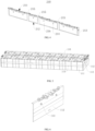
FIG. 1 is a schematic structural view of a battery pack according to an embodiment of the present disclosure; -
FIG. 2 is a schematic exploded view of a battery pack according to an embodiment of the present disclosure; -
FIG. 3 is a schematic structural view of a reinforcing assembly of a battery pack according to an embodiment of the present disclosure; -
FIG. 4 is a schematic structural view of a limiting plate of a battery pack according to an embodiment of the present disclosure; -
FIG. 5 is a schematic structural diagram of a battery module of a battery pack according to an embodiment of the present disclosure; -
FIG. 6 is a schematic structural view of an end plate of a battery pack according to an embodiment of the present disclosure. - Description of reference signs:
- 100, module assembly; 110, battery module; 111, battery core; 112, end plate; 113, second inserting and receiving portion; 114, loop; 115, seam;
- 200, reinforcing assembly; 210, limiting plate; 211, top portion; 212, bottom portion; 213, side surface; 214, first inserting and receiving portion; 215, limiting groove; 216, sinking table; 220, connecting member; 221, side connecting member; 222, intermediate connecting member; 223, connecting end;
- 300, lower case; 310, bottom wall; 320, side wall; 330, accommodating space;
- 400, pressing beam.
- Features and exemplary embodiments of various aspects of the present disclosure are described in detail below. In the following detailed description, numerous specific details are set forth to provide a comprehensive understanding of the present disclosure. However, it will be apparent to those skilled in the art that the present disclosure may be practiced without some of the details. The following description of the embodiments is merely provided to provide a better understanding of the present disclosure. In the drawings and the following description, at least some common structures and techniques are not shown in order to avoid unnecessary obscuring of the present disclosure. And for clarity, dimensions of some structures may be exaggerated. Furthermore, features, structures, or characteristics described hereinafter may be combined in any suitable manner in one or more embodiments.
- In the description of the present disclosure, it should be noted that, unless otherwise stated, the meaning of "multiple" is two or more; an orientation or positional relationship indicated by the terms "upper", "lower", "left", "right", "inside", "outside" is merely for conveniently and simply describing the present disclosure, does not indicate or imply that the device or component referred to has a specific orientation and is constructed and operated in a specific orientation, and therefore cannot be construed as a restriction to the present disclosure. Moreover, the terms "first", "second", etc. are used for descriptive purposes only and are not to be construed as indicating or implying relative importance.
- The terms concerning orientations appearing in the following description are all directions shown in the drawings, and are not intended to limit the specific structure of the embodiments of the present disclosure. In the description of the present disclosure, unless otherwise stated, it should also be noted that the terms "installation" and "connection" are to be understood broadly, and may be, for example, a fixed connection or a detachable connection, or an integral connection; and can be connected directly or indirectly. For those skilled in the art, the specific meanings of the above terms in the present disclosure can be understood as the case may be.
- For a better understanding of the present disclosure, the battery pack of the embodiment of the present disclosure will be described in detail below with reference to
FIGS. 1 to 6 . -
FIG. 1 is a schematic structural view of a battery pack according to an embodiment of the present disclosure. The battery pack includes amodule assembly 100 and a reinforcingassembly 200 for improving a connection strength between thebattery modules 110 in themodule assembly 100. - The
module assembly 100 includes two ormore battery modules 110. Each of thebattery modules 110 includes abattery core 111 and anend plate 112. The plurality ofbattery cores 111 are arranged side by side along a length direction of the battery pack (the Y direction inFIG. 1 ). Theend plate 112 is located on at least one side of the plurality ofbattery cores 111 in the length direction, and two ormore battery modules 110 are arranged side by side along a width direction of the battery pack (the X direction inFIG. 1 ). A limitingplate 210 is disposed on at least one side of themodule assembly 100 in the length direction and correspondingly to theend plate 112. The limitingplate 210 includes an inner side surface towards theend plate 112, and two or more first inserting and receivingportions 214 are provided on the inner side surface to correspond to two ormore end plates 112 respectively. A second inserting and receivingportion 113 is provided on a surface of theend plate 112 towards the limitingplate 210 to correspond to one of the first inserting and receivingportions 214. The two ormore battery modules 110 and the limitingplate 210 are coupled to each other via one of the first inserting and receivingportions 214 and the second inserting and receiving portion respectively. - In the present disclosure, the battery pack includes the
module assembly 100 and the limitingplate 210. Themodule assembly 100 includes a plurality ofbattery modules 110 arranged side by side in the width direction, and each of thebattery modules 110 includes theend plate 112. The first inserting and receivingportions 214 are provided on the inner side surface of the limitingplate 210, the second inserting and receivingportion 113 is provided on theend plate 112, and the plurality ofbattery modules 110 can be coupled to the limitingplate 210 via the second inserting and receivingportion 113 of theend plate 112 and one of the first inserting and receivingportions 214. Moreover, even if extending distances of thebattery modules 110 in the length direction are different, resulting in a length difference between thebattery modules 110, the length difference can be compensated for by the first inserting and receivingportions 214 and the second inserting and receivingportion 113. The stability of eachend plate 112, that is, a relative position between eachbattery module 110 and the limitingplate 210 is sufficiently ensured. Therefore, the plurality ofbattery modules 110 can be connected together via the limitingplate 210, and the plurality ofbattery modules 110 can be fixed between the limitingplate 210 and aside wall 320 of a battery pack case via the limitingplate 210. A connection strength between the plurality ofbattery modules 110 in the battery pack is improved. - The manner in which the battery pack is disposed is not limited thereto. In some optional embodiments, the battery pack further includes a
lower case 300. Thelower case 300 includes abottom wall 310 and aside wall 320 connected to each other, and anaccommodating space 330 surrounded by thebottom wall 310 and theside wall 320. Themodule assembly 100 and the limitingplate 210 are both disposed in theaccommodating space 330. - In some optional embodiments, in order to ensure that the limiting
plate 210 is stably located in theaccommodating space 330 of thelower case 300, thelower case 300 is further provided with apressing beam 400. Thepressing beam 400 and one of theside walls 320 are spaced apart to limit the limitingplate 210 and themodule assembly 100 between thepressing beam 400 and theside wall 320, so as to ensure the stability of the relative position between themodule assembly 100, the limitingplate 210 and thelower case 300. - In the battery pack, the plurality of
battery modules 110 are fixed between the limitingplate 210 and theside wall 320 via the limitingplate 210. - Referring to
FIG. 2 , the number of the limitingplates 210 is two. The two limitingplates 210 are spaced apart in the length direction, and themodule assembly 100 is located between the two limitingplates 210. Thebattery module 110 includes twoend plates 112 that are located on both sides of the plurality ofbattery cores 111 in the length direction. The first inserting and receivingportions 214 are respectively provided on the inner side surfaces of each of the two limitingplates 210, and the second inserting and receivingportion 113 is provided on each of theend plates 112 on both sides of the plurality ofbattery cores 111. Themodule assembly 100 is coupled between the two limitingplates 210 via one of the first inserting and receivingportions 214 and the second inserting and receivingportion 113 to further improve the connection strength between thebattery modules 110 in the battery pack. - As shown in
FIG. 3 , when the number of the limiting plates is two, and the two limitingplates 210 are disposed on both sides of themodule assembly 100, a connectingmember 220 is connected between the two limitingplates 210. The connectingmember 220 spans themodule assembly 100 and is connected between the two limitingplates 210 to ensure the stability of a relative position between the two limitingplates 210. - In some optional embodiments, the connecting
member 220 includes opposite connecting ends 223 in an extension direction thereof, and the connectingmember 220 is connected to one of the limitingplates 210 via the connecting ends 223. A limitinggroove 215 is provided on a surface of each of the limitingplates 210 to correspond to at least one of the connecting ends 223, so that the at least one connectingend 223 is limited to be located within the limitinggroove 215. In these optional embodiments, the limitinggroove 215 is provided on each of the limitingplates 210, and the connectingend 223 is disposed within the limitinggroove 215. The stability of the relative position between the limiting ends 223 and each of the limitingplates 210 can be improved via a limit of the limitinggroove 215. - The connection position of the connecting
member 220 and the limitingplate 210 is not limited. The limitingplate 210 includes atop portion 211 and abottom portion 212 that are oppositely disposed along a height direction of the battery pack (the Z direction inFIG. 1 ), and twoside surfaces 213 disposed opposite to each other in the width direction. The connectingmember 220 includes aside connecting member 221 and an intermediate connectingmember 222, theside connecting member 221 is connected to theside surface 213 of each of the limitingplates 210, and the intermediate connectingmember 222 is connected to thetop portion 211 of each of the limitingplates 210. - The number of the
side connecting members 221 is not limited. Preferably, the number of theside connecting members 221 is two, and the twoside connecting members 221 are respectively connected to twoside surfaces 213 of each of the limitingplates 210. The connection strength between thebattery modules 110 in the battery pack can be further improved via a limiting force in the width direction provided by the twoside connecting members 221 to themodule assembly 100. - The position of the intermediate connecting
member 222 is not limited herein, and the intermediate connectingmember 222 may be located in a gap between twoadjacent battery modules 110. Preferably, the intermediate connectingmember 222 spans above themodule assembly 100 so as not to increase a dimension of themodule assembly 100 in the width direction, thereby achieving space saving. - The position of the intermediate connecting
member 222 above themodule assembly 100 is not limited. Preferably, aseam 115 is formed between twobattery modules 110 adjacent in the width direction, and the intermediate connectingmember 222 is correspondingly disposed above theseam 115. Generally, a spacer assembly is provided above thebattery module 110, and the intermediate connectingmember 222 is disposed corresponding to theseam 115. A position can be reserved for the spacer assembly, especially when the connectingmember 220 is made of a conductive metal material, and the connectingmember 220 can be prevented from affecting the connection between components in the spacer assembly to improve the safety performance of the battery pack. - The number of the intermediate connecting
member 222 is not limited, and there may be only one intermediate connectingmember 222 or two or more intermediate connectingmembers 222. When the number of the intermediate connectingmembers 222 is two or more, two or more intermediate connectingmembers 222 are spaced apart in the width direction. - In any of the above embodiments, the manner in which the first inserting and receiving
portions 214 and the second inserting and receivingportion 113 are disposed is not limited herein. For example, referring toFIG. 4 to FIG. 6 , one of each of the first inserting and receivingportions 214 and the second inserting and receivingportion 113 is configured as a groove, and the other is configured as a convex column corresponding to the groove. The convex column is inserted into the groove to achieve a mutual insertion of each of the first inserting and receivingportions 214 and the second inserting and receivingportion 113. - Shapes of the groove and the convex column are not limited herein. Preferably, the groove is configured as a tapered groove, and the convex column is configured as a tapered convex column. Via the fitting of the tapered groove and convex column, each of the first inserting and receiving
portions 214 and the second inserting and receivingportion 113 can be tightly fitted, and each of the first inserting and receivingportions 214 and the second inserting and receivingportion 113 can also be aligned with each other. - In some embodiments, each of the first inserting and receiving
portions 214 is configured as the groove and the second inserting and receivingportion 113 is configured as the convex column fitting to the groove. The second inserting and receivingportion 113 disposed on theend plate 112 is configured as the convex column that does not weaken the strength of theend plate 112. The groove may be configured as a blind groove, or the groove may be configured as a through groove passing through the limitingplate 210. - When each of the first inserting and receiving
portions 214 is configured as the groove, the second inserting and receivingportion 113 is configured as the convex column, the groove is configured as the tapered groove, and the convex column is configured as the tapered convex column, the aperture of the groove is gradually reduced in a direction away from theend plate 112, and the cross section of the convex column is gradually reduced in a direction away from the surface of theend plate 112. The groove is configured as the tapered groove, which can increase the size of an opening of the groove. The convex column is configured as the tapered convex column, which can reduce the size of a free end of the convex column, thereby facilitating insertion of the convex column into the groove and facilitating the first inserting and receivingportion 214 and the second inserting and receivingportion 113 to be aligned with each other. - In some optional embodiments, each of the
battery modules 110 further includes aloop 114 that is sleeved on an outer periphery of theend plate 112 and protrudes from the surface of the plurality ofbattery cores 111. Theloop 114 protrudes from the surface of theend plate 112. The height of the convex column protruding from the surface of theend plate 112 is greater than the height of theloop 114 protruding from the surface of theend plate 112, and at least a portion of the convex column is located within the groove. - In these alternative embodiments, the height of the convex column protruding from the surface of the
end plate 112 is greater than the height of theloop 114 protruding from the surface of theend plate 112 such that the convex column can protrude from theloop 114. When each of the first inserting and receivingportions 214 and the second inserting and receivingportion 113 are inserted into each other, it is convenient to insert the convex column into the groove. - In order to further improve the stability of the relative position between each of the
battery module 110 and the limitingplate 210, in some optional embodiments, the inner side surface of the limitingplate 210 is recessed to form a sinking table 216, each of the first inserting and receivingportions 214 is located at the sinking table 216, and at least a portion of theend plate 112 is located within the sinking table 216. In these alternative embodiments, the sinking table 216 can limit theend plate 112 to further increase the stability of the relative position between theend plate 112 and the limitingplate 210. - The number of the second inserting and receiving
portion 113 on theend plate 112 is not limited, and theend plate 112 may be provided with one second inserting and receivingportion 113. Alternatively, two or more second inserting and receivingportions 113 may be provided on theend plate 112. The two second inserting and receivingportions 113 are spaced apart from each other on theend plate 112. Correspondingly, two or more first inserting and receivingportions 214 are provided on the limitingplate 210 to correspond to theend plate 112. The limitingplate 210 and theend plate 112 can be snap-connected to each other via two or more second inserting and receivingportions 113 and two or more first inserting and receivingportions 214, thereby further improving the stability of the relative position between the limitingplate 210 and theend plate 112. - The present embodiments are to be considered in all respects as illustrative and non-restrictive. The scope of the present invention is defined by the appended claims rather than the above description.
Claims (8)
- A battery pack, comprising:a module assembly (100) comprising two or more battery modules (110), wherein each of the battery modules (110) comprises an end plate (112) anda plurality of battery cores (111) arranged side by side along a length direction (Y) of the battery pack, the end plate (112) is located on at least one side of the plurality of battery cores (111) in the length direction (y), and the two or more battery modules (110) are arranged side by side along a width direction (X) of the battery pack; anda limiting plate (210) disposed on at least one side of the module assembly (100) in the length direction (Y) and correspondingly to the end plates (112), wherein the limiting plate (210) comprises an inner side surface towards the end plates (112), two or more first inserting and receiving portions (214) are provided on the inner side surface to correspond to two or more end plates (112) respectively, second inserting and receiving portions (113) are provided on the surface of the end plates (112) towards the limiting plate (210) to correspond to the first inserting and receiving portions (214), and the two or more battery modules (110) are coupled with the limiting plate (210) via one of the first inserting and receiving portions (214) and one of the second inserting and receiving portions (113) respectively, each of the first inserting and receiving portions (214) is configured as a groove, and each of the second inserting and receiving portions (113) is configured as a convex column fitting to the groove;the groove is configured as a tapered groove, an aperture of the groove is gradually reduced in a direction away from the end plates (112), and the convex column is configured as a tapered convex column, and a cross section of the convex column is gradually reduced in a direction away from the end plates (112), andthe battery pack further comprises a lower case (300) comprising a bottom wall (310), a side wall (320) connected to each other, and an accommodating space (330) surrounded by the bottom wall (310) and the side wall (320), and the module assembly (100) and the limiting plates (210) are both disposed in the accommodating space (330).
- The battery pack according to one of claim 1, wherein each of the battery modules (110) further comprises a loop (114) disposed on outer peripheries of the end plates (112) and the plurality of battery cores (111), the loop (114) is configured to protrude from surfaces of the end plates (112), a height of the convex column protruding from the surfaces of the end plates (112) is greater than a height of the loop (114) protruding from the surfaces of the end plates (112), and at least a portion of the convex column is located within the groove.
- The battery pack according to one of claims 1 to 2, wherein the inner side surface is recessed to form a sinking table (216), each of the first inserting and receiving portions (214) is disposed on the sinking table (216), and at least a part of each of the end plates (112) is located within the sinking table (216).
- The battery pack according to one of claims 1 to 3, wherein each of the battery modules (110) comprises two end plates (112), and the two end plates (112) are respectively disposed on two sides of the plurality of battery cores (111) in the length direction (Y); and
the number of the limiting plates (210) is two and the two limiting plates (210) are disposed on two sides of the module assembly (100) in the length direction (Y), the inner side surfaces of the two limiting plates (210) are provided with the first inserting and receiving portions (214), and the end plates (112) are provided with the second inserting and receiving portions (113). - The battery pack according to one of claims 1 to 4, wherein the number of the limiting plates (210) is two, and the two limiting plates (210) are respectively disposed on two sides of the module assembly (100) in the length direction (Y); and
the battery pack further comprises a connecting member (220) spanning the module assembly (100) and connected between the two limiting plates (210). - The battery pack according to claim 5, wherein each of the limiting plates (210) include a top portion (211) and a bottom portion (212) disposed opposite to each other in a height direction (Z) of the battery pack, and two side surfaces disposed opposite to each other in the width direction (X); and
the connecting member (220) comprises a side connecting member (221) connected to a side surface of each of the limiting plates (210), and an intermediate connecting member (222) connected to the top portion (211) of each of the limiting plates (210). - The battery pack according to claim 6, wherein the number of the intermediate connecting members (222) is two or more, and the two or more intermediate connecting members (222) are spaced apart in the width direction (X);
and/or, a seam (115) is formed between the two adjacent battery modules (110) in the width direction (X), and the intermediate connecting member (110) is correspondingly disposed above the seam (115). - The battery pack according to one of claims 5 to 7, wherein the connecting member (220) comprises two connecting ends (223) disposed opposite to each other in an extension direction of the connecting member (220), and the connecting member (220) is connected to each of the limiting plates (210) via the connecting ends (223); and
a limiting groove (215) is provided on a surface of each of the limiting plates (210) to correspond to at least one of the two connecting ends (223), so that the at least one of the two connecting ends (223) is limited to be located within the limiting groove (215).
Applications Claiming Priority (2)
| Application Number | Priority Date | Filing Date | Title |
|---|---|---|---|
| CN201921154826.8U CN210073967U (en) | 2019-07-22 | 2019-07-22 | Battery pack |
| PCT/CN2019/097912 WO2021012290A1 (en) | 2019-07-22 | 2019-07-26 | Battery pack |
Publications (3)
| Publication Number | Publication Date |
|---|---|
| EP3790073A1 EP3790073A1 (en) | 2021-03-10 |
| EP3790073A4 EP3790073A4 (en) | 2021-03-31 |
| EP3790073B1 true EP3790073B1 (en) | 2023-12-20 |
Family
ID=69430232
Family Applications (1)
| Application Number | Title | Priority Date | Filing Date |
|---|---|---|---|
| EP19769982.0A Active EP3790073B1 (en) | 2019-07-22 | 2019-07-26 | Battery pack |
Country Status (4)
| Country | Link |
|---|---|
| US (1) | US11721869B2 (en) |
| EP (1) | EP3790073B1 (en) |
| CN (1) | CN210073967U (en) |
| WO (1) | WO2021012290A1 (en) |
Families Citing this family (1)
| Publication number | Priority date | Publication date | Assignee | Title |
|---|---|---|---|---|
| CN212659640U (en) * | 2020-07-28 | 2021-03-05 | 厦门海辰新能源科技有限公司 | Battery module fixing assembly and battery pack |
Family Cites Families (14)
| Publication number | Priority date | Publication date | Assignee | Title |
|---|---|---|---|---|
| JP4117865B2 (en) * | 1999-08-31 | 2008-07-16 | 松下電器産業株式会社 | Assembled battery |
| KR100821442B1 (en) * | 2005-05-31 | 2008-04-10 | 마쯔시다덴기산교 가부시키가이샤 | Non-aqueous electrolyte secondary battery and battery module |
| US20070087266A1 (en) * | 2005-10-18 | 2007-04-19 | Debbi Bourke | Modular battery system |
| JP2008282582A (en) | 2007-05-08 | 2008-11-20 | Sanyo Electric Co Ltd | Battery pack |
| JP2011175743A (en) * | 2010-02-23 | 2011-09-08 | Sanyo Electric Co Ltd | Power source apparatus, and vehicle equipped with the same |
| US8968912B2 (en) * | 2011-12-21 | 2015-03-03 | Ford Global Technologies, Llc | Method and apparatus for manufacturing a battery for a vehicle |
| JP5928800B2 (en) * | 2012-05-22 | 2016-06-01 | トヨタ自動車株式会社 | Nonaqueous electrolyte secondary battery |
| JP6168599B2 (en) * | 2013-09-02 | 2017-07-26 | 株式会社Gsユアサ | Power storage device |
| US10312485B2 (en) * | 2015-07-23 | 2019-06-04 | Ford Global Technologies, Llc | Battery assembly array plate |
| CN207398218U (en) * | 2017-09-21 | 2018-05-22 | 宁德时代新能源科技股份有限公司 | Battery modules |
| CN110323376B (en) | 2018-03-30 | 2020-09-01 | 宁德时代新能源科技股份有限公司 | End plate for battery module and battery module |
| CN208986062U (en) | 2018-11-14 | 2019-06-14 | 北京普莱德新能源电池科技有限公司 | A kind of battery modules heating device and battery modules |
| CN209104213U (en) | 2018-12-07 | 2019-07-12 | 蜂巢能源科技有限公司 | Battery modules and battery pack |
| CN209183611U (en) | 2018-12-29 | 2019-07-30 | 宁德时代新能源科技股份有限公司 | Battery modules |
-
2019
- 2019-07-22 CN CN201921154826.8U patent/CN210073967U/en active Active
- 2019-07-26 EP EP19769982.0A patent/EP3790073B1/en active Active
- 2019-07-26 WO PCT/CN2019/097912 patent/WO2021012290A1/en unknown
- 2019-07-26 US US16/499,268 patent/US11721869B2/en active Active
Also Published As
| Publication number | Publication date |
|---|---|
| US20210336308A1 (en) | 2021-10-28 |
| EP3790073A1 (en) | 2021-03-10 |
| US11721869B2 (en) | 2023-08-08 |
| EP3790073A4 (en) | 2021-03-31 |
| WO2021012290A1 (en) | 2021-01-28 |
| CN210073967U (en) | 2020-02-14 |
Similar Documents
| Publication | Publication Date | Title |
|---|---|---|
| EP3270439B1 (en) | Battery module | |
| EP2490276B1 (en) | Battery module with superior structural stability | |
| US11056747B2 (en) | Battery module | |
| US11114726B2 (en) | Battery box | |
| JP2007299544A (en) | Battery pack | |
| US10886518B2 (en) | Separator assembly and battery module | |
| EP3800695A1 (en) | Battery box and battery module | |
| EP3905371B1 (en) | Battery box and battery module | |
| EP3790073B1 (en) | Battery pack | |
| US11742544B2 (en) | Battery module | |
| CN115995651A (en) | Battery pack and electricity utilization device | |
| CN116868424A (en) | Box and battery pack | |
| US10840485B2 (en) | Composite end plate and battery module | |
| CN209981308U (en) | Battery module frame and battery module | |
| US20240113377A1 (en) | Battery module and battery pack | |
| US11329347B2 (en) | Battery pack and vehicle | |
| CN219759912U (en) | Battery device | |
| CN213636185U (en) | Module frame and battery module | |
| CN216720191U (en) | End plate of battery module | |
| CN219419328U (en) | Battery pack | |
| CN219759858U (en) | Battery device | |
| CN219801140U (en) | CTP battery mounting structure and battery pack | |
| US20230307755A1 (en) | Storage rack, energy storage frame, and energy storage battery cluster | |
| CN211828973U (en) | Upper shell of battery pack and battery pack | |
| CN215988992U (en) | Separator, battery module and device |
Legal Events
| Date | Code | Title | Description |
|---|---|---|---|
| STAA | Information on the status of an ep patent application or granted ep patent |
Free format text: STATUS: UNKNOWN |
|
| STAA | Information on the status of an ep patent application or granted ep patent |
Free format text: STATUS: THE INTERNATIONAL PUBLICATION HAS BEEN MADE |
|
| PUAI | Public reference made under article 153(3) epc to a published international application that has entered the european phase |
Free format text: ORIGINAL CODE: 0009012 |
|
| STAA | Information on the status of an ep patent application or granted ep patent |
Free format text: STATUS: REQUEST FOR EXAMINATION WAS MADE |
|
| REG | Reference to a national code |
Ref country code: DE Ref legal event code: R079 Ref document number: 602019043637 Country of ref document: DE Free format text: PREVIOUS MAIN CLASS: H01M0002100000 Ipc: H01M0010420000 Ref country code: DE Ref legal event code: R079 Free format text: PREVIOUS MAIN CLASS: H01M0002100000 Ipc: H01M0010420000 |
|
| 17P | Request for examination filed |
Effective date: 20190927 |
|
| AK | Designated contracting states |
Kind code of ref document: A1 Designated state(s): AL AT BE BG CH CY CZ DE DK EE ES FI FR GB GR HR HU IE IS IT LI LT LU LV MC MK MT NL NO PL PT RO RS SE SI SK SM TR |
|
| AX | Request for extension of the european patent |
Extension state: BA ME |
|
| A4 | Supplementary search report drawn up and despatched |
Effective date: 20210226 |
|
| RIC1 | Information provided on ipc code assigned before grant |
Ipc: H01M 50/258 20210101ALI20210222BHEP Ipc: H01M 50/204 20210101ALI20210222BHEP Ipc: H01M 50/264 20210101ALI20210222BHEP Ipc: H01M 10/42 20060101AFI20210222BHEP |
|
| STAA | Information on the status of an ep patent application or granted ep patent |
Free format text: STATUS: EXAMINATION IS IN PROGRESS |
|
| 17Q | First examination report despatched |
Effective date: 20211027 |
|
| DAV | Request for validation of the european patent (deleted) | ||
| DAX | Request for extension of the european patent (deleted) | ||
| GRAP | Despatch of communication of intention to grant a patent |
Free format text: ORIGINAL CODE: EPIDOSNIGR1 |
|
| STAA | Information on the status of an ep patent application or granted ep patent |
Free format text: STATUS: GRANT OF PATENT IS INTENDED |
|
| INTG | Intention to grant announced |
Effective date: 20231011 |
|
| GRAS | Grant fee paid |
Free format text: ORIGINAL CODE: EPIDOSNIGR3 |
|
| GRAA | (expected) grant |
Free format text: ORIGINAL CODE: 0009210 |
|
| STAA | Information on the status of an ep patent application or granted ep patent |
Free format text: STATUS: THE PATENT HAS BEEN GRANTED |
|
| AK | Designated contracting states |
Kind code of ref document: B1 Designated state(s): AL AT BE BG CH CY CZ DE DK EE ES FI FR GB GR HR HU IE IS IT LI LT LU LV MC MK MT NL NO PL PT RO RS SE SI SK SM TR |
|
| REG | Reference to a national code |
Ref country code: GB Ref legal event code: FG4D |
|
| REG | Reference to a national code |
Ref country code: CH Ref legal event code: EP |
|
| REG | Reference to a national code |
Ref country code: DE Ref legal event code: R096 Ref document number: 602019043637 Country of ref document: DE |
|
| REG | Reference to a national code |
Ref country code: IE Ref legal event code: FG4D |
|
| P01 | Opt-out of the competence of the unified patent court (upc) registered |
Effective date: 20240104 |
|
| PG25 | Lapsed in a contracting state [announced via postgrant information from national office to epo] |
Ref country code: GR Free format text: LAPSE BECAUSE OF FAILURE TO SUBMIT A TRANSLATION OF THE DESCRIPTION OR TO PAY THE FEE WITHIN THE PRESCRIBED TIME-LIMIT Effective date: 20240321 |
|
| REG | Reference to a national code |
Ref country code: LT Ref legal event code: MG9D |
|
| PG25 | Lapsed in a contracting state [announced via postgrant information from national office to epo] |
Ref country code: LT Free format text: LAPSE BECAUSE OF FAILURE TO SUBMIT A TRANSLATION OF THE DESCRIPTION OR TO PAY THE FEE WITHIN THE PRESCRIBED TIME-LIMIT Effective date: 20231220 |