EP2116689B2 - Spacer profile for a spacer frame for an insulating window unit and insulating window unit - Google Patents
Spacer profile for a spacer frame for an insulating window unit and insulating window unit Download PDFInfo
- Publication number
- EP2116689B2 EP2116689B2 EP09010884.6A EP09010884A EP2116689B2 EP 2116689 B2 EP2116689 B2 EP 2116689B2 EP 09010884 A EP09010884 A EP 09010884A EP 2116689 B2 EP2116689 B2 EP 2116689B2
- Authority
- EP
- European Patent Office
- Prior art keywords
- profile
- spacer
- window panes
- spacer profile
- intervening space
- Prior art date
- Legal status (The legal status is an assumption and is not a legal conclusion. Google has not performed a legal analysis and makes no representation as to the accuracy of the status listed.)
- Active
Links
- 125000006850 spacer group Chemical group 0.000 title claims abstract description 110
- 239000000463 material Substances 0.000 claims abstract description 49
- 239000002184 metal Substances 0.000 claims abstract description 32
- 229910052751 metal Inorganic materials 0.000 claims abstract description 32
- 229920002994 synthetic fiber Polymers 0.000 claims abstract description 15
- 239000000853 adhesive Substances 0.000 claims description 7
- 230000001070 adhesive effect Effects 0.000 claims description 7
- 230000004308 accommodation Effects 0.000 claims description 6
- 229910000831 Steel Inorganic materials 0.000 claims description 4
- ATJFFYVFTNAWJD-UHFFFAOYSA-N Tin Chemical compound [Sn] ATJFFYVFTNAWJD-UHFFFAOYSA-N 0.000 claims description 4
- -1 polypropylene Polymers 0.000 claims description 4
- 238000000926 separation method Methods 0.000 claims description 4
- 229910001220 stainless steel Inorganic materials 0.000 claims description 4
- 239000010935 stainless steel Substances 0.000 claims description 4
- 239000010959 steel Substances 0.000 claims description 4
- 239000004743 Polypropylene Substances 0.000 claims description 3
- 229920001155 polypropylene Polymers 0.000 claims description 3
- 239000003566 sealing material Substances 0.000 claims description 3
- HCHKCACWOHOZIP-UHFFFAOYSA-N Zinc Chemical compound [Zn] HCHKCACWOHOZIP-UHFFFAOYSA-N 0.000 claims description 2
- 230000007797 corrosion Effects 0.000 claims description 2
- 238000005260 corrosion Methods 0.000 claims description 2
- 238000007747 plating Methods 0.000 claims description 2
- 229920000098 polyolefin Polymers 0.000 claims description 2
- 230000000087 stabilizing effect Effects 0.000 claims description 2
- 229910052725 zinc Inorganic materials 0.000 claims description 2
- 239000011701 zinc Substances 0.000 claims description 2
- 238000009792 diffusion process Methods 0.000 description 28
- 230000004888 barrier function Effects 0.000 description 20
- 230000037373 wrinkle formation Effects 0.000 description 11
- 238000005452 bending Methods 0.000 description 9
- 239000007789 gas Substances 0.000 description 9
- 238000013461 design Methods 0.000 description 5
- 239000004033 plastic Substances 0.000 description 5
- 229920003023 plastic Polymers 0.000 description 5
- 238000007789 sealing Methods 0.000 description 5
- 238000012360 testing method Methods 0.000 description 5
- 150000001875 compounds Chemical class 0.000 description 4
- 238000000034 method Methods 0.000 description 4
- 230000009467 reduction Effects 0.000 description 4
- 230000037303 wrinkles Effects 0.000 description 4
- 230000015572 biosynthetic process Effects 0.000 description 3
- 239000002131 composite material Substances 0.000 description 3
- XKRFYHLGVUSROY-UHFFFAOYSA-N Argon Chemical compound [Ar] XKRFYHLGVUSROY-UHFFFAOYSA-N 0.000 description 2
- IJGRMHOSHXDMSA-UHFFFAOYSA-N Atomic nitrogen Chemical compound N#N IJGRMHOSHXDMSA-UHFFFAOYSA-N 0.000 description 2
- 239000011248 coating agent Substances 0.000 description 2
- 238000000576 coating method Methods 0.000 description 2
- 230000006835 compression Effects 0.000 description 2
- 238000007906 compression Methods 0.000 description 2
- 238000001125 extrusion Methods 0.000 description 2
- 238000009413 insulation Methods 0.000 description 2
- 238000005259 measurement Methods 0.000 description 2
- 230000008569 process Effects 0.000 description 2
- 230000002787 reinforcement Effects 0.000 description 2
- VYZAMTAEIAYCRO-UHFFFAOYSA-N Chromium Chemical compound [Cr] VYZAMTAEIAYCRO-UHFFFAOYSA-N 0.000 description 1
- 229920005372 Plexiglas® Polymers 0.000 description 1
- 239000004952 Polyamide Substances 0.000 description 1
- 229920002367 Polyisobutene Polymers 0.000 description 1
- 239000012080 ambient air Substances 0.000 description 1
- 229910052786 argon Inorganic materials 0.000 description 1
- QVGXLLKOCUKJST-UHFFFAOYSA-N atomic oxygen Chemical compound [O] QVGXLLKOCUKJST-UHFFFAOYSA-N 0.000 description 1
- 230000008901 benefit Effects 0.000 description 1
- 230000005540 biological transmission Effects 0.000 description 1
- 125000000484 butyl group Chemical group [H]C([*])([H])C([H])([H])C([H])([H])C([H])([H])[H] 0.000 description 1
- ZCDOYSPFYFSLEW-UHFFFAOYSA-N chromate(2-) Chemical compound [O-][Cr]([O-])(=O)=O ZCDOYSPFYFSLEW-UHFFFAOYSA-N 0.000 description 1
- 239000004020 conductor Substances 0.000 description 1
- 230000000593 degrading effect Effects 0.000 description 1
- 230000001419 dependent effect Effects 0.000 description 1
- 238000011161 development Methods 0.000 description 1
- 230000018109 developmental process Effects 0.000 description 1
- 238000006073 displacement reaction Methods 0.000 description 1
- 238000011156 evaluation Methods 0.000 description 1
- 230000004927 fusion Effects 0.000 description 1
- 239000011521 glass Substances 0.000 description 1
- 230000002427 irreversible effect Effects 0.000 description 1
- 229910052743 krypton Inorganic materials 0.000 description 1
- DNNSSWSSYDEUBZ-UHFFFAOYSA-N krypton atom Chemical compound [Kr] DNNSSWSSYDEUBZ-UHFFFAOYSA-N 0.000 description 1
- 238000004519 manufacturing process Methods 0.000 description 1
- 150000002739 metals Chemical class 0.000 description 1
- 238000012986 modification Methods 0.000 description 1
- 230000004048 modification Effects 0.000 description 1
- 229910052757 nitrogen Inorganic materials 0.000 description 1
- 239000001301 oxygen Substances 0.000 description 1
- 229910052760 oxygen Inorganic materials 0.000 description 1
- 229920002647 polyamide Polymers 0.000 description 1
- 229920000515 polycarbonate Polymers 0.000 description 1
- 239000004417 polycarbonate Substances 0.000 description 1
- 229920000139 polyethylene terephthalate Polymers 0.000 description 1
- 239000005020 polyethylene terephthalate Substances 0.000 description 1
- 239000004926 polymethyl methacrylate Substances 0.000 description 1
- 229920001021 polysulfide Polymers 0.000 description 1
- 239000005077 polysulfide Substances 0.000 description 1
- 150000008117 polysulfides Polymers 0.000 description 1
- 229920002635 polyurethane Polymers 0.000 description 1
- 239000004814 polyurethane Substances 0.000 description 1
- 238000007665 sagging Methods 0.000 description 1
- 229910052710 silicon Inorganic materials 0.000 description 1
- 239000010703 silicon Substances 0.000 description 1
- 239000005028 tinplate Substances 0.000 description 1
- 230000007704 transition Effects 0.000 description 1
- XLYOFNOQVPJJNP-UHFFFAOYSA-N water Substances O XLYOFNOQVPJJNP-UHFFFAOYSA-N 0.000 description 1
- 229910001868 water Inorganic materials 0.000 description 1
- 229910052724 xenon Inorganic materials 0.000 description 1
- FHNFHKCVQCLJFQ-UHFFFAOYSA-N xenon atom Chemical compound [Xe] FHNFHKCVQCLJFQ-UHFFFAOYSA-N 0.000 description 1
Images


Classifications
-
- E—FIXED CONSTRUCTIONS
- E06—DOORS, WINDOWS, SHUTTERS, OR ROLLER BLINDS IN GENERAL; LADDERS
- E06B—FIXED OR MOVABLE CLOSURES FOR OPENINGS IN BUILDINGS, VEHICLES, FENCES OR LIKE ENCLOSURES IN GENERAL, e.g. DOORS, WINDOWS, BLINDS, GATES
- E06B3/00—Window sashes, door leaves, or like elements for closing wall or like openings; Layout of fixed or moving closures, e.g. windows in wall or like openings; Features of rigidly-mounted outer frames relating to the mounting of wing frames
- E06B3/66—Units comprising two or more parallel glass or like panes permanently secured together
- E06B3/663—Elements for spacing panes
- E06B3/66309—Section members positioned at the edges of the glazing unit
- E06B3/66314—Section members positioned at the edges of the glazing unit of tubular shape
- E06B3/66319—Section members positioned at the edges of the glazing unit of tubular shape of rubber, plastics or similar materials
-
- E—FIXED CONSTRUCTIONS
- E06—DOORS, WINDOWS, SHUTTERS, OR ROLLER BLINDS IN GENERAL; LADDERS
- E06B—FIXED OR MOVABLE CLOSURES FOR OPENINGS IN BUILDINGS, VEHICLES, FENCES OR LIKE ENCLOSURES IN GENERAL, e.g. DOORS, WINDOWS, BLINDS, GATES
- E06B3/00—Window sashes, door leaves, or like elements for closing wall or like openings; Layout of fixed or moving closures, e.g. windows in wall or like openings; Features of rigidly-mounted outer frames relating to the mounting of wing frames
- E06B3/66—Units comprising two or more parallel glass or like panes permanently secured together
- E06B3/663—Elements for spacing panes
- E06B3/66309—Section members positioned at the edges of the glazing unit
- E06B3/66323—Section members positioned at the edges of the glazing unit comprising an interruption of the heat flow in a direction perpendicular to the unit
-
- E—FIXED CONSTRUCTIONS
- E06—DOORS, WINDOWS, SHUTTERS, OR ROLLER BLINDS IN GENERAL; LADDERS
- E06B—FIXED OR MOVABLE CLOSURES FOR OPENINGS IN BUILDINGS, VEHICLES, FENCES OR LIKE ENCLOSURES IN GENERAL, e.g. DOORS, WINDOWS, BLINDS, GATES
- E06B3/00—Window sashes, door leaves, or like elements for closing wall or like openings; Layout of fixed or moving closures, e.g. windows in wall or like openings; Features of rigidly-mounted outer frames relating to the mounting of wing frames
- E06B3/66—Units comprising two or more parallel glass or like panes permanently secured together
- E06B3/673—Assembling the units
- E06B3/67304—Preparing rigid spacer members before assembly
-
- E—FIXED CONSTRUCTIONS
- E06—DOORS, WINDOWS, SHUTTERS, OR ROLLER BLINDS IN GENERAL; LADDERS
- E06B—FIXED OR MOVABLE CLOSURES FOR OPENINGS IN BUILDINGS, VEHICLES, FENCES OR LIKE ENCLOSURES IN GENERAL, e.g. DOORS, WINDOWS, BLINDS, GATES
- E06B3/00—Window sashes, door leaves, or like elements for closing wall or like openings; Layout of fixed or moving closures, e.g. windows in wall or like openings; Features of rigidly-mounted outer frames relating to the mounting of wing frames
- E06B3/66—Units comprising two or more parallel glass or like panes permanently secured together
- E06B3/663—Elements for spacing panes
- E06B3/66309—Section members positioned at the edges of the glazing unit
- E06B2003/6638—Section members positioned at the edges of the glazing unit with coatings
Definitions
- the present invention relates to spacer profiles and to insulating window units incorporating the present spacer profiles.
- Insulating window units having at least two window panes, which are held apart from each other in the insulating window unit, are known.
- Insulating windows are normally formed from an inorganic or organic glass or from other materials like Plexiglas.
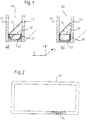
- the spacer frame is either assembled from several pieces using connectors or is bent from one piece (see Fig. 2 ), so that then the spacer frame 50 is closable by a connector 54 at only one position.
- the intervening space between the panes is preferably filled with inert, insulating gas, e.g., such as argon, krypton, xenon, etc.
- inert, insulating gas e.g., such as argon, krypton, xenon, etc.
- this filling gas should not be permitted leak out of the intervening space between the panes. Consequently, the intervening space between the panes must be sealed accordingly.
- nitrogen, oxygen, water, etc., contained in the ambient air naturally also should not be permitted enter into the intervening space between the panes. Therefore, the spacer profile must be designed so as to prevent such diffusion.
- vapor diffusion impermeability as well as also gas diffusion impermeability for the gases relevant herein, are meant to be encompassed within the meaning thereof.
- the heat transmission of the edge connection i.e. the connection of the frame of the insulating window unit, of the window panes, and of the spacer frame, in particular, plays a very large role for achieving low heat conduction of these insulating window units.
- Insulating window units which ensure high heat insulation along the edge connection, fulfill "warm edge" conditions as this term is utilized in the art.
- spacer profiles were manufactured from metal. Such metal spacer profiles can not, however, fulfill "warm edge” conditions. Thus, in order to improve upon such metal spacer profiles, the provision of synthetic material on the metal spacer profile has been described, e.g., in US 4,222,213 or DE 102 26 268 A1 .
- Such composite spacer profiles use a profile body made of synthetic material with a metal film, which should be as thin as possible in order to satisfy the "warm edge” conditions, but should have a certain minimum thickness in order to guarantee diffusion impermeability and strength.
- metal is a substantially better heat conductor than synthetic material, it has been attempted, e.g., to design the heat conduction path between the side edges/walls of the spacer profile (i.e. through or via the metal film) to be as long as possible (see EP 1 017 923 A1 ).
- the spacer frame is preferably bent from a one-piece spacer profile, if possible by cold bending (at a room temperature of approximately 20°C), whereby only one position that potentially impairs the gas impermeability is provided, i.e. the gap between the respective ends of the bent spacer frame.
- a connector is affixed to the bent spacer frame in order to close and seal this gap.
- a composite spacer profile is also known from EP 0 601 488 A2 (family member US 5,460,862 ), wherein a stiffening support is embedded on the side of the profile that faces toward the intervening space between the panes in the assembled state.
- US 5,890,289 discloses another composite spacer.
- US 4,109,431 discloses a ceiling and spacing unit for multiple glazed windows with a spacer-dehydrator element to be positioned between the window panes.
- Improved insulating window units with such spacer profiles are alternate objects of the invention.
- a spacer profile may preferably comprise a profile body made of synthetic material.
- One or more chambers for accommodating hygroscopic material are preferably defined within the profile body.
- a metal film preferably substantially or completely encloses the profile body on three-sides, e.g. an outer side and two side walls thereof.
- the metal film preferably has sufficient thickness to serve as a gas/vapor impermeable (diffusion-proof or essentially diffusion-proof) layer.
- the spacer profile when bent into a spacer profile frame and disposed between two window panes, the (e.g., inner) side of the profile body that is not covered with the metal film is arranged to be directed towards the intervening space between two window panes of an insulating window unit.
- the not-enclosed (not-metal covered) inner side of the profile body preferably comprises openings and/or one or more materials adapted to facilitate moisture exchange between hygroscopic material, which is preferably accommodated in the chamber(s) when the spacer profile its final assembled state, and the intervening space between the window panes.
- each end of the metal film preferably comprises a profile (or elongation portion) formed adjacent to the respective side walls and close to the inner side of the spacer profile that will face toward the intervening space between the window panes in the bent/assembled state.
- the profile(s) or elongation portion(s) include at least one edge or bend.
- the profile(s) may define a flange with respect to the portion of the metal film covering or disposed on the side walls of the profile body.
- spacer profiles preferably may be used as spacer profile frames, which may be mounted along the edge area of an insulating window unit for forming and securing the intervening space between the window panes.
- the present teachings encompass insulating window units comprising at least two window panes and one or more of the spacer profiles disclosed herein.
- the spacer profiles include the above-mentioned metal profiles
- the sag along unsupported, extended portions of the spacer frame also preferably can be reduced, preferably significantly reduced, especially when using the spacer profile for large frames.
- the length (in the cross-section perpendicular to the longitudinal direction) of the profile or elongation portion, and thus the mass of the diffusion barrier film additionally introduced in this region or area of the spacer profile, can be significantly increased.
- a displacement of the bend line results therefrom, which further results in a reduction of wrinkle formation.
- the sag is substantially reduced, because the bent, angled and/or folded profile/elongation portion adds significant strength to the structural integrity of the bent spacer frame.
- the spacer profile is shown in cross-section perpendicular to a longitudinal direction, i.e. along a slice in the X-Y plane, and extends with this constant cross-section in the longitudinal direction.
- the spacer profile comprises a height h1 in the height direction Y and is comprised of a profile body 10, which is formed from a first material.
- the first material is preferably an elastic-plastic deformable, poor heat conducting (insulating) material.
- the term “elastic-plastic deformable” preferably means that elastic restoring forces are active in the material after a bending process, as is typically the case for synthetic materials for which only a part of the bending takes place with a plastic, irreversible deformation.
- the term “poor heat conducting” preferably means that the heat conduction value ⁇ is less than or equal to about 0.3 W/(mK).
- the first material is preferably a synthetic material, more preferably a polyolefin and still more preferably polypropylene, polyethylene terephthalate, polyamide or polycarbonate.
- An example of such a polypropylene is Novolen® 1040K.
- the first material preferably has an E-modulus of less than or equal to about 2200 N/mm 2 and a heat conduction value ⁇ less than or equal to about 0.3 W/(mK), preferably less than or equal to about 0.2 W/(mK).
- the profile body 10 is firmly bonded (e.g., fusion and/or adhesive bonded) with a one-piece diffusion barrier film 30.
- the diffusion barrier film 30 is formed from a second material.
- the second material is preferably a plastic deformable material.
- plastic deformable preferably means that practically no elastic restoring forces are active after the deformation. This is typically the case, for example, when metals are bent beyond their elastic limit (apparent yield limit).
- the second material is a metal, more preferably stainless steel or steel having a corrosion protection of tin (such as tin plating) or zinc. If necessary or desired, a chrome coating or a chromate coating may be applied thereto.
- the term "firmly bonded” preferably means that the profile body 10 and the diffusion barrier film 30 are durably connected with each other, e.g. by co-extrusion of the profile body with the diffusion barrier film, and/or if necessary, by the application of an adhesive material.
- the cohesiveness of the connection is sufficiently large that the materials are not separable in the peel test according to DIN 53282.
- the diffusion barrier film additionally also preferably acts as a reinforcement element.
- Its thickness (material thickness) d1 is less than or equal to 0.20 mm, more preferably less than or equal to 0.15 mm, still more preferably less than or equal to 0.12 mm, and still more preferably less than or equal to 0.10 mm.
- the maximum thickness is chosen so as to correspond to the desired heat conduction value. As the film is made thinner, the "warm edge" conditions will be increasingly fulfilled.
- Each of the embodiments shown in the figures preferably has a thickness in the range of 0.05 mm - 0.13 mm
- the preferred material for the diffusion barrier film is steel and/or stainless steel having a heat conduction value of ⁇ less than or equal to about 50 W/(mK), more preferably less than or equal to about 25 W/(mK) and still more preferably 15 less than or equal to W/(mK).
- the E-modulus of the second material preferably falls in the range of about 170-240 kN/mm 2 and is preferably about 210 hN/mm 2 .
- the breaking elongation of the second material is preferably greater than or equal to about 15%, and more preferably greater than or equal to about 20%.
- An example of stainless steel film is the steel film 1.4301 or 1.4016 according to DIN EN 10 08812 having a thickness of 0.05 mm and an example of a tin plate film is a film made of Antralyt E2, 8/2, 8T57 having a thickness of 0.125 mm.
- the profile body 10 comprises an inner wall 13 and an outer wall 14 separated by a distance h2 in the height direction Y and two side walls 11, 12 that are separated by a distance in the traverse direction X, and extend essentially in the height direction Y.
- the side walls 11, 12 are connected via the inner wall 13 and outer wall 14, so that a chamber 20 is formed for accommodating hygroscopic material.
- the chamber 20 is defined on its respective sides in cross-section by the walls 11-14 of the profile body.
- the chamber 20 comprises a height h2 in the height direction Y.
- the side walls 11, 12 are formed as attachment bases for attachment to the inner sides of the window panes. In other words, the spacer profile is preferably adhered to the respective inner sides of the window panes via these attachment bases (see Fig. 1 ).
- the inner wall 13 is defined herein as the "inner” wall, because it faces inward toward the intervening space between the window panes in the assembled state of the spacer profile.
- This side of the spacer profile, which faces towards the intervening space between the window panes, is designated in the following description as the inner side in the height direction of the spacer profile.
- the side walls 11, 12 each comprise a concave portion, when observed from outside of the chamber 20, which concave portion forms the transition or segue of the outer wall 14 to the corresponding side wall 11, 12.
- the heat conduction path via the metal film is elongated as compared to the U-configuration shown in Fig. 4a ), even though the W- and U-configurations have the same height h1 and width b1.
- the volume of the chamber 20, with the same width b1 and height h1 is slightly reduced.
- Openings 15 are formed in the inner wall 13, independent of the choice of the material for the profile body, so that the inner wall 11 is not formed to be diffusion-proof.
- the formation of the openings 15 is preferable. In any case, moisture exchange between the intervening space between the window panes and the hygroscopic material in the chamber 20 in the assembled state is preferably ensured (see also Fig. 1 ).
- the diffusion barrier film 30 is formed on the outer sides of the outer wall 14 and the side walls 11, 12, which face away from the chamber 20.
- the film 30 expends along the side walls in the height direction Y up to height h2 of the chamber 20.
- Adjacent thereto, the one-piece diffusion barrier film 30 comprises profiled elongation portions 31, 32, each having a profile 31a, 32a.
- the term "profile" preferably means that the elongation portion is not exclusively a linear elongation of the diffusion barrier film 30, but instead that a two-dimensional profile is formed in the two-dimensional view of the cross-section in the X-Y plane, which profile is formed, for example, by one or more bends and/or angles in the elongation portion 31, 32.
- the profile 31a, 32a comprises a bend (90°) and a portion (flange) directly adjacent thereto, which portion (flange) extends a length 11 in the traverse direction X from the outer edge of the corresponding side wall 11, 12 toward the interior.
- At least one side of the diffusion barrier profile is preferably firmly bonded to the profile body.
- the largest part of the elongation portion is completely enclosed by the material of the profile body.
- the elongation portion is preferably disposed as close as possible to the inner side of the spacer profile.
- the diffusion barrier film preferably should not be visible through the window panes of the assembled insulating window unit. Therefore, the film preferably should be covered at the inner side by the material of the profile body.
- the material of the profile body One embodiment, in which this is not the case, will be described later with reference to Fig. 6 .
- the elongation portion should preferably be close to the inner side. Therefore, the region of the profile body (accommodation region), in which the elongation portion is located (is accommodated), preferably should be clearly above the mid-line of the profile in the height direction. In such case, the dimension (length) of the accommodation region from the inner side of the spacer profile in the Y-direction should not extend over more than 40% of the height of the spacer profile.
- the accommodation region 16, 17 comprises a height h3 in the height direction and the height h3 should be less than or equal to about 0.4 h1, preferably less than or equal to about 0.3 h1, more preferably less than or equal to about 0.2 h1 and still more preferably less than or equal to about 0.1 h1.
- the mass (weight) of the elongation portion comprises at least about 10% of the mass (weight) of the remaining part of the diffusion barrier film, which is above the mid-line of the spacer profile in the height direction, preferably at least about 20%, more preferably at least about 50% and still more preferably about 100%.
- a spacer profile according to a second embodiment is shown in cross-section in the X-Y plane.
- the second embodiment differs from the first embodiment in that the elongation portions 31, 32 are almost double the length of the first embodiment, whereby the elongation length 11 stays the same. This is achieved by including a second bend (180°) in the profiles 31b, 32b and by extending the portion of the elongation portion, which is continuous with the second end, likewise in the traverse direction X, but now to the outside. A substantially longer length of the elongation portion is thereby ensured, whereby the closest possible proximity to the inner side of the spacer profile is maintained.
- the diffusion barrier film 30, inclusive of the elongation portions 31, 32 extends completely along the outside of the profile body 10.
- the elongation portions 31, 32 and their profiles 31c, 32c are thus visible on the inner side (the "outside" facing the space between the window panes) in the assembled state, because the elongation portions 31, 32 are not covered at the inner side by the material of the profile body, but rather are exposed.
- the elongation portion is arranged as close as possible to the inner side.
- Fig. 6 could be modified so that the elongation portion 31, 32 is elongated and, similar to the embodiment shown in Fig. 5 (or also in Figs. 7-9 ), extends into the interior of the accommodation region 16, 17. Naturally, the height h3 shown in Fig. 6c ) and d) would then be correspondingly longer.
- FIGs. 7a ) and b cross-sectional views of a spacer profile according to a fourth embodiment are shown.
- the fourth embodiment differs from the first embodiment, in that the bend is not a 90° bend, but rather is a 180° bend. Consequently, the bend-adjacent portion of the elongation portion next to the profiles 31 d, 32d does not extend in the traverse direction X, but rather extends in the height direction Y. Therefore, the three-sided enclosure of a part of the material of the profile body reaches into the accommodation regions 16, 17, although only one bend is present. Therefore, as in the previous embodiment, during bending of the spacer profile with compression, a volume element is present that can effectively act as an essentially incompressible volume element.
- FIGs. 8a) and 8b cross-sectional views of a spacer profile according to a fifth embodiment are shown.
- the fifth embodiment differs from the fourth embodiment merely in that the curvature radius of the bend of the profile 31 e, 32e is smaller than in the fourth embodiment.
- FIGs. 9a) and 9b cross-sectional views of a spacer profile according to a sixth embodiment are shown.
- the sixth embodiment differs from the first to fifth embodiments, which are shown in Figs. 4-8 , in that the profiles 31f, 32f comprise first a bend of about 45° towards the interior, then a bend of about 45° in the opposite direction and finally a 180° bend having a corresponding three-sided embedding of a part of the material of the profile body.
- FIGs. 10a) and 10b comparison examples of spacer profiles having the W-configuration and the U-configuration are shown, which comparison examples do not comprise a profiled elongation portion.
- Fig. 10c shows a table with measurement values for the test arrangement according to Fig. 3b ).
- a spacer profile lies on two supports separated by distance L, whereby the sag D is measured as compared to an ideal not-sagging profile (i.e. a straight line between the two support points).
- an ideal not-sagging profile i.e. a straight line between the two support points.
- FIGs. 11a ) and b cross-sectional views of a spacer profile according to a seventh embodiment are shown.
- the seventh embodiment differs from the sixth embodiment, in that a 180° bend is not present in the profiles 31 g and 31g.
- the significant reduction of the wrinkle formation in the bends results in that better adhesion and sealing with the inner side of the window panes can be achieved.
- the reduction of the sag results in that, in particular for large spacer profile frames, i.e. for large window widths, less manual effort is required to affix the spacer profile so as to prevent any visible sag.
- a spacer profile frame made of a spacer profile according to one of the above-described embodiments results also in that the ultimately obtained frame is closer to the ideal form, which is shown in Fig. 2 , than the less ideal form, which is shown in Fig. 3a ).
- the spacer profile frame whether it is produced from one-piece by bending, preferably cold bending, or it is produced from several straight individual pieces using corner connectors, is used in an insulating window unit, e.g. in the form shown in Fig. 1 . In Fig. 1 , the elongation portions are not depicted.
- the side walls 11, 12 formed as attachment bases are adhered with the inner sides of the window panes 51, 52 using an adhesive material (primary sealing compound) 61, e.g., a butyl sealing compound based upon polyisobutylene.
- the intervening space 53 between the window panes is thus defined by the two window panes 51, 52 and the spacer profile 50.
- the inner side of the spacer profile 50 faces the intervening space 53 between the window panes 51, 52.
- a mechanically stabilizing sealing material for example based upon polysulfide, polyurethane or silicon, is introduced into the remaining, empty space between the inner sides of the window panes in order to fill the empty space.
- This sealing compound also protects the diffusion barrier layer from mechanical or other corrosive/degrading influences.
- the diffusion barrier film 30 with the profile body 10 is achieved by co-extrusion in firmly bonding contact.
- more than just one side of the diffusion barrier profile formed by a metal film comes into contact with the material, preferably synthetic material, of the profile body.
- the firmly bonded connection, i.e. the adhesion, between the metal and the synthetic material is to be ensured by an adhesive material applied to the metal film.
- Methods for manufacturing a spacer profile (50) for use as a spacer profile frame, which is suitable for mounting in and/or along the edge area of an insulating window unit for forming and maintaining an intervening space (53) between window panes (51, 52), may comprise the steps of forming one or more chambers (20) in a profile body (10) made of synthetic material.
- a metal film (30) may be disposed on and/or in at least three sides of the profile body (10) such that, when bent, a fourth, uncovered side of the profile body (10) will be directed towards the intervening space (53) between the window panes (51, 52) in the assembled insulating window unit, the metal film causing the at least three covered sides to be substantially gas impermeable, whereas the fourth side of the profile body (10) is gas permeable.
- Each end of the metal film (30) is preferably formed with a profile (31 a-g, 32a-g) having at least one edge or bend.
Abstract
Description
- This application claims priority to
U.S. provisional application no. 60/608,221, filed 9 September 2004 - The present invention relates to spacer profiles and to insulating window units incorporating the present spacer profiles.
- Insulating window units having at least two window panes, which are held apart from each other in the insulating window unit, are known. Insulating windows are normally formed from an inorganic or organic glass or from other materials like Plexiglas. Normally, the separation of the window panes is secured by a spacer frame (see
reference number 50 inFig. 1 ). The spacer frame is either assembled from several pieces using connectors or is bent from one piece (seeFig. 2 ), so that then thespacer frame 50 is closable by aconnector 54 at only one position. - Various designs have been utilized for insulating window units that are intended to provide good heat insulation. According to one design, the intervening space between the panes is preferably filled with inert, insulating gas, e.g., such as argon, krypton, xenon, etc. Naturally, this filling gas should not be permitted leak out of the intervening space between the panes. Consequently, the intervening space between the panes must be sealed accordingly. Moreover, nitrogen, oxygen, water, etc., contained in the ambient air naturally also should not be permitted enter into the intervening space between the panes. Therefore, the spacer profile must be designed so as to prevent such diffusion. In the description below, when the term "diffusion impermeability" is utilized with respect to the spacer profiles and/or the materials forming the spacer profile, vapor diffusion impermeability, as well as also gas diffusion impermeability for the gases relevant herein, are meant to be encompassed within the meaning thereof.
- Furthermore, the heat transmission of the edge connection, i.e. the connection of the frame of the insulating window unit, of the window panes, and of the spacer frame, in particular, plays a very large role for achieving low heat conduction of these insulating window units. Insulating window units, which ensure high heat insulation along the edge connection, fulfill "warm edge" conditions as this term is utilized in the art.
- Conventionally, spacer profiles were manufactured from metal. Such metal spacer profiles can not, however, fulfill "warm edge" conditions. Thus, in order to improve upon such metal spacer profiles, the provision of synthetic material on the metal spacer profile has been described, e.g., in
US 4,222,213 orDE 102 26 268 A1 . - Although a spacer, which exclusively consists of a synthetic material having a low heat conduction value, could be expected to fulfill the "warm edge" conditions, the requirements of diffusion impermeability and strength would be very difficult to satisfy.
- Other known solutions include spacer profiles made of synthetic material that are provided with a metal film as a diffusion barrier and reinforcement layer, as shown, e.g., in
EP 0 953 715 A2US 6,192,652 ) orEP 1 017 923 (family memberUS 6,339,909 ). - Such composite spacer profiles use a profile body made of synthetic material with a metal film, which should be as thin as possible in order to satisfy the "warm edge" conditions, but should have a certain minimum thickness in order to guarantee diffusion impermeability and strength.
- Because metal is a substantially better heat conductor than synthetic material, it has been attempted, e.g., to design the heat conduction path between the side edges/walls of the spacer profile (i.e. through or via the metal film) to be as long as possible (see
EP 1 017 923 A1 ). - For improved gas impermeability, the spacer frame is preferably bent from a one-piece spacer profile, if possible by cold bending (at a room temperature of approximately 20°C), whereby only one position that potentially impairs the gas impermeability is provided, i.e. the gap between the respective ends of the bent spacer frame. A connector is affixed to the bent spacer frame in order to close and seal this gap.
- When the spacer profile is bent, in particular when cold bending techniques are used, there is a problem of wrinkle formation at the bends (see
Fig. 3c ). The advantage of cold bending is, as was already mentioned above, that superior diffusion impermeability and increased durability of the insulating window unit result. - According to the solution known from
EP 1 017 923 A1 , the problem of wrinkle formation has been well solved, but the space available in the chamber for the desiccating material is not satisfactory, in particular for small distances between panes, i.e. separation distances less than 12 mm, and more particularly for separation distances of 6, 8 or 10 mm. According to other solutions, such as those shown, e.g., inFig. 1 ofEP 0 953 715 A2Fig. 3a and 3b ). - A composite spacer profile is also known from
EP 0 601 488 A2US 5,460,862 ), wherein a stiffening support is embedded on the side of the profile that faces toward the intervening space between the panes in the assembled state.US 5,890,289 discloses another composite spacer.US 4,109,431 discloses a ceiling and spacing unit for multiple glazed windows with a spacer-dehydrator element to be positioned between the window panes. - It is an object of the invention to provide improved spacer profiles, which preferably fulfill the "warm edge" conditions and reduce the problem of wrinkle formation while maximizing the chamber volume for the desiccating material. Improved insulating window units with such spacer profiles are alternate objects of the invention.
- One or more of these objects is/are solved by the subject-matter(s) of the independent claim(s) 1 and/or 7.
- Further developments of the invention are provided in the dependent claims.
- According to the present teachings, a spacer profile may preferably comprise a profile body made of synthetic material. One or more chambers for accommodating hygroscopic material are preferably defined within the profile body. A metal film preferably substantially or completely encloses the profile body on three-sides, e.g. an outer side and two side walls thereof. In addition, the metal film preferably has sufficient thickness to serve as a gas/vapor impermeable (diffusion-proof or essentially diffusion-proof) layer. Preferably, when the spacer profile is bent into a spacer profile frame and disposed between two window panes, the (e.g., inner) side of the profile body that is not covered with the metal film is arranged to be directed towards the intervening space between two window panes of an insulating window unit.
- In addition, the not-enclosed (not-metal covered) inner side of the profile body preferably comprises openings and/or one or more materials adapted to facilitate moisture exchange between hygroscopic material, which is preferably accommodated in the chamber(s) when the spacer profile its final assembled state, and the intervening space between the window panes.
- In addition, each end of the metal film (diffusion barrier) preferably comprises a profile (or elongation portion) formed adjacent to the respective side walls and close to the inner side of the spacer profile that will face toward the intervening space between the window panes in the bent/assembled state. The profile(s) or elongation portion(s) include at least one edge or bend. In preferred embodiments, the profile(s) may define a flange with respect to the portion of the metal film covering or disposed on the side walls of the profile body.
- Such spacer profiles preferably may be used as spacer profile frames, which may be mounted along the edge area of an insulating window unit for forming and securing the intervening space between the window panes. Thus, the present teachings encompass insulating window units comprising at least two window panes and one or more of the spacer profiles disclosed herein.
- When the spacer profiles include the above-mentioned metal profiles, the sag along unsupported, extended portions of the spacer frame also preferably can be reduced, preferably significantly reduced, especially when using the spacer profile for large frames.
- If the profile or elongation portion has a bent, angled and/or folded configuration, the length (in the cross-section perpendicular to the longitudinal direction) of the profile or elongation portion, and thus the mass of the diffusion barrier film additionally introduced in this region or area of the spacer profile, can be significantly increased. A displacement of the bend line results therefrom, which further results in a reduction of wrinkle formation. Furthermore, the sag is substantially reduced, because the bent, angled and/or folded profile/elongation portion adds significant strength to the structural integrity of the bent spacer frame.
- Additional features and objects will be apparent from the description of the exemplary embodiments with consideration of the figures.
-
-
Figs. 1a ) and b) respectively show perspective cross-sectional views of the configuration of the window pane in an insulating window unit, in which a spacer profile, adhesive material and sealing material are arranged therebetween. -
Fig. 2 shows a side view, partially cut away, of a spacer frame bent from a spacer profile in the ideal condition. -
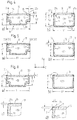
Fig. 3a ) shows a side view, partially cut away, of a spacer frame bent from a spacer profile in a real condition with an illustrated sag (droop or downward deformation) between imaginary supports on the upper bar;Fig. 3b ) shows an imaginary test arrangement; andFig. 3c ) shows the wrinkle formation at a bend. -
Figs. 4a) and 4b ) show cross-sectional views of a spacer profile according to a first embodiment, respectively in a W-configuration and in a U-configuration. -
Figs. 5a) and 5b ) show cross-sectional views of a spacer profile according to a second embodiment, respectively in a W-configuration and in a U-configuration. -
Figs. 6a) and 6b ) show cross-sectional views of a spacer profile according to a third embodiment not covered by the claims, respectively in a W-configuration and in a U-configuration;Fig. 6c ) shows an enlarged view of the portion encircled by a circle inFig. 6a) and Fig. 6d ) shows an enlarged view of the portion encircled by a circle inFig. 6b ). -
Figs. 7a) and 7b ) show a cross-sectional view of a spacer profile according to a fourth embodiment, respectively in a W-configuration and in a U-configuration. -
Figs. 8a) and 8b ) show a cross-sectional view of a spacer profile according to a fifth embodiment, respectively in a W-configuration and in a U-configuration. -
Figs. 9a) and 9b ) show a cross-sectional view of a spacer profile according to a sixth embodiment, respectively in a W-configuration and in a V-configuration. -
Figs. 10a) and 10b ) show cross-sectional views of a spacer profile according to a comparison example (i.e. not having a profiled elongation portion), respectively in a W-configuration and in a U-configuration;Fig. 10c ) shows a table with values for the spacer profiles according toFig. 4-10 that were evaluated in a test arrangement according toFig. 3 . -
Figs. 11a) and 11b ) show cross-section views of a spacer profile according to a seventh embodiment, respectively in a W-configuration and in a U-configuration. -
Fig. 12 shows a table representing evaluation results of the wrinkle formation behavior of the spacer profiles ofFig. 4-11 . - Embodiments of the present teachings will be described in greater detail below with references to the figures. The same features/elements are marked with the same reference numbers in all figures. For the purpose of clarity, all reference numbers have not been inserted into all figures. The 3-dimensional (X, Y, Z) reference system shown in
Fig. 1 , betweenFigs. 5 and 6 and betweenFigs. 8 and 9 is applicable to all figures and the description and the claims. The longitudinal direction corresponds to the direction Z, the traverse direction corresponds to the direction X and the height direction corresponds to the direction Y. - In
Figures 1 ,4-9 and11 , a so-called W-configuration of the spacer profile is shown in each a) view and a so-called U-configuration is shown in each b) view. A spacer profile according to a first embodiment will now be described with reference toFigs. 4a) and 4b ). - In
Figs. 4a) and 4b ), the spacer profile is shown in cross-section perpendicular to a longitudinal direction, i.e. along a slice in the X-Y plane, and extends with this constant cross-section in the longitudinal direction. The spacer profile comprises a height h1 in the height direction Y and is comprised of aprofile body 10, which is formed from a first material. The first material is preferably an elastic-plastic deformable, poor heat conducting (insulating) material. - Herein, the term "elastic-plastic deformable" preferably means that elastic restoring forces are active in the material after a bending process, as is typically the case for synthetic materials for which only a part of the bending takes place with a plastic, irreversible deformation. Further, the term "poor heat conducting" preferably means that the heat conduction value λ is less than or equal to about 0.3 W/(mK).
- The first material is preferably a synthetic material, more preferably a polyolefin and still more preferably polypropylene, polyethylene terephthalate, polyamide or polycarbonate. An example of such a polypropylene is Novolen® 1040K. The first material preferably has an E-modulus of less than or equal to about 2200 N/mm2 and a heat conduction value λ less than or equal to about 0.3 W/(mK), preferably less than or equal to about 0.2 W/(mK).
- The
profile body 10 is firmly bonded (e.g., fusion and/or adhesive bonded) with a one-piecediffusion barrier film 30. Thediffusion barrier film 30 is formed from a second material. The second material is preferably a plastic deformable material. Herein, the term "plastic deformable" preferably means that practically no elastic restoring forces are active after the deformation. This is typically the case, for example, when metals are bent beyond their elastic limit (apparent yield limit). Preferably, the second material is a metal, more preferably stainless steel or steel having a corrosion protection of tin (such as tin plating) or zinc. If necessary or desired, a chrome coating or a chromate coating may be applied thereto. - Herein, the term "firmly bonded" preferably means that the
profile body 10 and thediffusion barrier film 30 are durably connected with each other, e.g. by co-extrusion of the profile body with the diffusion barrier film, and/or if necessary, by the application of an adhesive material. Preferably, the cohesiveness of the connection is sufficiently large that the materials are not separable in the peel test according to DIN 53282. - Furthermore, the diffusion barrier film additionally also preferably acts as a reinforcement element. Its thickness (material thickness) d1 is less than or equal to 0.20 mm, more preferably less than or equal to 0.15 mm, still more preferably less than or equal to 0.12 mm, and still more preferably less than or equal to 0.10 mm. The maximum thickness is chosen so as to correspond to the desired heat conduction value. As the film is made thinner, the "warm edge" conditions will be increasingly fulfilled. Each of the embodiments shown in the figures preferably has a thickness in the range of 0.05 mm - 0.13 mm
- The preferred material for the diffusion barrier film is steel and/or stainless steel having a heat conduction value of λ less than or equal to about 50 W/(mK), more preferably less than or equal to about 25 W/(mK) and still more preferably 15 less than or equal to W/(mK). The E-modulus of the second material preferably falls in the range of about 170-240 kN/mm2 and is preferably about 210 hN/mm2. The breaking elongation of the second material is preferably greater than or equal to about 15%, and more preferably greater than or equal to about 20%. An example of stainless steel film is the steel film 1.4301 or 1.4016 according to
DIN EN 10 08812 having a thickness of 0.05 mm and an example of a tin plate film is a film made of Antralyt E2, 8/2, 8T57 having a thickness of 0.125 mm. - Further details of the materials that may be advantageously used with the present teachings are described in greater detail in
EP 1 017 923 A1/B1 US 6,339,909 ), the contents of which are incorporated herein by reference. - The
profile body 10 comprises aninner wall 13 and anouter wall 14 separated by a distance h2 in the height direction Y and twoside walls side walls inner wall 13 andouter wall 14, so that achamber 20 is formed for accommodating hygroscopic material. Thechamber 20 is defined on its respective sides in cross-section by the walls 11-14 of the profile body. Thechamber 20 comprises a height h2 in the height direction Y. Theside walls Fig. 1 ). - The
inner wall 13 is defined herein as the "inner" wall, because it faces inward toward the intervening space between the window panes in the assembled state of the spacer profile. This side of the spacer profile, which faces towards the intervening space between the window panes, is designated in the following description as the inner side in the height direction of the spacer profile. Theouter wall 14, which is arranged in the height direction Y on the opposite side of thechamber 20, faces away from the intervening space between the window panes in the assembled state and therefore is defined herein as the "outer" wall. - According to the W-configuration shown in
Fig. 4a ), theside walls chamber 20, which concave portion forms the transition or segue of theouter wall 14 to thecorresponding side wall Fig. 4a ), even though the W- and U-configurations have the same height h1 and width b1. In exchange, the volume of thechamber 20, with the same width b1 and height h1, is slightly reduced. -
Openings 15 are formed in theinner wall 13, independent of the choice of the material for the profile body, so that theinner wall 11 is not formed to be diffusion-proof. In addition or in the alternative, to achieve a non-diffusion-proof design, it is also possible to select the material for the entire profile body and/or the inner wall, such that the material permits an equivalent diffusion without the formation of theopenings 15. However, the formation of theopenings 15 is preferable. In any case, moisture exchange between the intervening space between the window panes and the hygroscopic material in thechamber 20 in the assembled state is preferably ensured (see alsoFig. 1 ). - The
diffusion barrier film 30 is formed on the outer sides of theouter wall 14 and theside walls chamber 20. Thefilm 30 expends along the side walls in the height direction Y up to height h2 of thechamber 20. Adjacent thereto, the one-piecediffusion barrier film 30 comprises profiledelongation portions profile 31a, 32a. - Herein, the term "profile" preferably means that the elongation portion is not exclusively a linear elongation of the
diffusion barrier film 30, but instead that a two-dimensional profile is formed in the two-dimensional view of the cross-section in the X-Y plane, which profile is formed, for example, by one or more bends and/or angles in theelongation portion - According to the embodiment shown in
Fig. 4 , theprofile 31a, 32a comprises a bend (90°) and a portion (flange) directly adjacent thereto, which portion (flange) extends alength 11 in the traverse direction X from the outer edge of thecorresponding side wall - For the firmly bonded connection of the
profile body 10 and thediffusion barrier film 30, at least one side of the diffusion barrier profile is preferably firmly bonded to the profile body. According to the embodiment shown inFig. 4 , the largest part of the elongation portion is completely enclosed by the material of the profile body. The elongation portion is preferably disposed as close as possible to the inner side of the spacer profile. - On the other hand, for purely ornamental reasons, the diffusion barrier film preferably should not be visible through the window panes of the assembled insulating window unit. Therefore, the film preferably should be covered at the inner side by the material of the profile body. One embodiment, in which this is not the case, will be described later with reference to
Fig. 6 . - In summary, the elongation portion should preferably be close to the inner side. Therefore, the region of the profile body (accommodation region), in which the elongation portion is located (is accommodated), preferably should be clearly above the mid-line of the profile in the height direction. In such case, the dimension (length) of the accommodation region from the inner side of the spacer profile in the Y-direction should not extend over more than 40% of the height of the spacer profile. In other words, the
accommodation region - Moreover, it is advantageous if the mass (weight) of the elongation portion comprises at least about 10% of the mass (weight) of the remaining part of the diffusion barrier film, which is above the mid-line of the spacer profile in the height direction, preferably at least about 20%, more preferably at least about 50% and still more preferably about 100%.
- All details concerning the first embodiment also apply to all the other described embodiments, except when a difference is expressly noted or is shown in the figures.
- In
Figs. 5a) and 5b ), a spacer profile according to a second embodiment is shown in cross-section in the X-Y plane. - The second embodiment differs from the first embodiment in that the
elongation portions elongation length 11 stays the same. This is achieved by including a second bend (180°) in theprofiles - In addition, a part of the material of the profile body is enclosed on three sides by the
profiles - Referring to
Figs. 6a) and 6b ), a spacer profile according to a third embodiment not covered by the claims will be described, wherein the areas surrounded by a circle respectively in views a) and b) are shown enlarged inFigs. 6c ) and d). According to the embodiment shown inFig. 6 , thediffusion barrier film 30, inclusive of theelongation portions profile body 10. Theelongation portions profiles elongation portions - The embodiment shown in
Fig. 6 could be modified so that theelongation portion Fig. 5 (or also inFigs. 7-9 ), extends into the interior of theaccommodation region Fig. 6c ) and d) would then be correspondingly longer. - In
Figs. 7a ) and b), cross-sectional views of a spacer profile according to a fourth embodiment are shown. The fourth embodiment differs from the first embodiment, in that the bend is not a 90° bend, but rather is a 180° bend. Consequently, the bend-adjacent portion of the elongation portion next to theprofiles accommodation regions - In
Figs. 8a) and 8b ). cross-sectional views of a spacer profile according to a fifth embodiment are shown. The fifth embodiment differs from the fourth embodiment merely in that the curvature radius of the bend of theprofile - In
Figs. 9a) and 9b ), cross-sectional views of a spacer profile according to a sixth embodiment are shown. The sixth embodiment differs from the first to fifth embodiments, which are shown inFigs. 4-8 , in that theprofiles - In
Figs. 10a) and 10b ), comparison examples of spacer profiles having the W-configuration and the U-configuration are shown, which comparison examples do not comprise a profiled elongation portion.Fig. 10c ) shows a table with measurement values for the test arrangement according toFig. 3b ). In the test arrangement ofFig. 3b ), a spacer profile lies on two supports separated by distance L, whereby the sag D is measured as compared to an ideal not-sagging profile (i.e. a straight line between the two support points). For the data provided in the table ofFig. 10c ), L = 2000 mm, b1 = 15.3 mm, h1 for the W-configuration = 7 mm and b1 = 13.3 mm, h1 for the U-configuration = 8.4 mm. For all embodiments of the profile, the same materials, material thickness, wall thickness, etc., were utilized. The data are partially based upon measurements and partially upon calculations. - The reduction of the sag for all embodiments shown in
Figs. 4-9 , as compared to the spacer profiles ofFig. 10 , was remarkably nearly 20% or more. - In
Figs. 11a ) and b), cross-sectional views of a spacer profile according to a seventh embodiment are shown. The seventh embodiment differs from the sixth embodiment, in that a 180° bend is not present in theprofiles - For spacer profiles according to the present teachings, it was also determined that the wrinkle formation in the bends, as represented schematically in
Fig. 3c ), for all embodiments, which are shown inFigs. 4-9 and11 , was significantly reduced as compared to the comparison examples ofFig. 10 . In other words, the number of wrinkles and/or the length of the wrinkles were reduced in the bent spacer profiles according to the present teachings. The wrinkle formation behavior of the respective spacer profiles, which was evaluated based upon the number of wrinkles and/or the lengths of the wrinkles, is represented in the table ofFig. 12 , in which "+" means reduced wrinkle formation and "++" means significantly reduced wrinkle formation with respect to the comparison example (Fig. 10 ). - Further modifications of the profile of the
elongation portions - The significant reduction of the wrinkle formation in the bends results in that better adhesion and sealing with the inner side of the window panes can be achieved. The reduction of the sag results in that, in particular for large spacer profile frames, i.e. for large window widths, less manual effort is required to affix the spacer profile so as to prevent any visible sag.
- A spacer profile frame made of a spacer profile according to one of the above-described embodiments results also in that the ultimately obtained frame is closer to the ideal form, which is shown in
Fig. 2 , than the less ideal form, which is shown inFig. 3a ). The spacer profile frame, whether it is produced from one-piece by bending, preferably cold bending, or it is produced from several straight individual pieces using corner connectors, is used in an insulating window unit, e.g. in the form shown inFig. 1 . InFig. 1 , the elongation portions are not depicted. - As is shown in
Fig. 1 , theside walls window panes space 53 between the window panes is thus defined by the twowindow panes spacer profile 50. The inner side of thespacer profile 50 faces the interveningspace 53 between thewindow panes space 53 between the window panes in the height direction Y, a mechanically stabilizing sealing material (secondary sealing compound), for example based upon polysulfide, polyurethane or silicon, is introduced into the remaining, empty space between the inner sides of the window panes in order to fill the empty space. This sealing compound also protects the diffusion barrier layer from mechanical or other corrosive/degrading influences. - As was already mentioned above, the
diffusion barrier film 30 with theprofile body 10 is achieved by co-extrusion in firmly bonding contact. According to the embodiments shown inFigs. 4, 5 ,7-9 and11 , more than just one side of the diffusion barrier profile formed by a metal film comes into contact with the material, preferably synthetic material, of the profile body. In particular, by using synthetic material and metal, the firmly bonded connection, i.e. the adhesion, between the metal and the synthetic material is to be ensured by an adhesive material applied to the metal film. - Methods for manufacturing a spacer profile (50) for use as a spacer profile frame, which is suitable for mounting in and/or along the edge area of an insulating window unit for forming and maintaining an intervening space (53) between window panes (51, 52), may comprise the steps of forming one or more chambers (20) in a profile body (10) made of synthetic material. Either simultaneous with or subsequent to the chamber forming step, a metal film (30) may be disposed on and/or in at least three sides of the profile body (10) such that, when bent, a fourth, uncovered side of the profile body (10) will be directed towards the intervening space (53) between the window panes (51, 52) in the assembled insulating window unit, the metal film causing the at least three covered sides to be substantially gas impermeable, whereas the fourth side of the profile body (10) is gas permeable. Each end of the metal film (30) is preferably formed with a profile (31 a-g, 32a-g) having at least one edge or bend.
Claims (7)
- Spacer profile (50) for use as a spacer profile frame, which is suitable for mounting in and/or along the edge area of an insulating window unit for forming and maintaining an intervening space (53) between window panes (51, 52), the spacer profile (50) comprising:a profile body (10) made of synthetic material and defining one or more chambers (20) for accommodating hygroscopic material therein, anda metal film (30) enclosing the profile body (10) on three sides such that, in the bent and/or assembled state of the spacer profile (50), the non-enclosed inner side of the profile body is directed towards the intervening space (53) between the window panes (51, 52),wherein the not-enclosed inner side of the profile body (10) comprises openings (15) adapted to facilitate moisture exchange between hygroscopic material accommodated in the chamber(s) (20) and the intervening space (53) between the window panes (51, 52), characterized in thatthe spacer profile (50) is cold bendable, the metal film (30) has a first thickness d1 greater than or equal to 0.03 mm and less than or equal to 0.20 mm,the metal film (30) comprises a profile (31a-g, 32a-g) on each end that is directed towards the intervening space (53) between the window panes (51, 52), the profile having at least one edge or bend, andthe profile (31a, b, d-g, 32a, b, d-g) is completely enclosed by the profile body (10).
- Spacer profile according to claim 1, wherein
the profile body (10) defines therein a chamber (20) for accommodation of hygroscopic material, which is laterally defined by side walls (11, 12). - Spacer profile according to claim 2, wherein
the corresponding; side walls (11, 12) are formed as an attachment base for attachment to the inner side of the window panes. - Spacer profile according to any one of the preceding claims, wherein
the synthetic material is polyolefin such as polypropylene. - Spacer profile according to any one of the preceding claims, wherein
the metal is stainless steel or steel having a corrosion protection made of tin (tin plating) or zinc. - Spacer profile according to any one of the preceding claims, wherein
the first thickness d1 of the metal film (30) is greater than or equal to 0.03 mm and less than or equal to 0.10 mm. - Insulating window unit comprising:at least two window panes (51, 52) arranged to oppose each other with a separation distance therebetween so as to form an intervening space (53) between the window panes (51, 52), characterized in that the insulating window unit comprisesa spacer profile frame formed from a spacer profile (50) according to any one of claims 1 to 6 and at least partially defining the intervening space (53) between the window panes (51, 52),wherein the attachment bases of the spacer profile (50) are adhered with a diffusion-proof adhesive material (61) essentially along their entire length and height with the inner side of the window panes (51, 52) that faces thereto, andthe remaining empty space between the inner sides of the window panes (51, 52) on the side of the spacer profile frame and the adhesive material (61) that faces away from the intervening space (53) between the window panes (51, 52) is filled with a mechanically stabilizing sealing material (62).
Priority Applications (1)
| Application Number | Priority Date | Filing Date | Title |
|---|---|---|---|
| PL09010884T PL2116689T5 (en) | 2004-09-09 | 2005-08-30 | Spacer profile for a spacer frame for an insulating window unit and insulating window unit |
Applications Claiming Priority (3)
| Application Number | Priority Date | Filing Date | Title |
|---|---|---|---|
| US60822104P | 2004-09-09 | 2004-09-09 | |
| PCT/EP2005/009349 WO2006027146A1 (en) | 2004-09-09 | 2005-08-30 | Spacer profile for a spacer frame for an insulating window unit and insulating window unit |
| EP05782712A EP1797271B1 (en) | 2004-09-09 | 2005-08-30 | Spacer profile for a spacer frame for an insulating window unit and insulating window unit |
Related Parent Applications (2)
| Application Number | Title | Priority Date | Filing Date |
|---|---|---|---|
| EP05782712.3 Division | 2005-08-30 | ||
| EP05782712A Division EP1797271B1 (en) | 2004-09-09 | 2005-08-30 | Spacer profile for a spacer frame for an insulating window unit and insulating window unit |
Publications (4)
| Publication Number | Publication Date |
|---|---|
| EP2116689A2 EP2116689A2 (en) | 2009-11-11 |
| EP2116689A3 EP2116689A3 (en) | 2012-06-13 |
| EP2116689B1 EP2116689B1 (en) | 2016-03-23 |
| EP2116689B2 true EP2116689B2 (en) | 2020-08-19 |
Family
ID=35385609
Family Applications (2)
| Application Number | Title | Priority Date | Filing Date |
|---|---|---|---|
| EP05782712A Active EP1797271B1 (en) | 2004-09-09 | 2005-08-30 | Spacer profile for a spacer frame for an insulating window unit and insulating window unit |
| EP09010884.6A Active EP2116689B2 (en) | 2004-09-09 | 2005-08-30 | Spacer profile for a spacer frame for an insulating window unit and insulating window unit |
Family Applications Before (1)
| Application Number | Title | Priority Date | Filing Date |
|---|---|---|---|
| EP05782712A Active EP1797271B1 (en) | 2004-09-09 | 2005-08-30 | Spacer profile for a spacer frame for an insulating window unit and insulating window unit |
Country Status (15)
| Country | Link |
|---|---|
| US (2) | US7827760B2 (en) |
| EP (2) | EP1797271B1 (en) |
| JP (1) | JP4680998B2 (en) |
| KR (1) | KR100829974B1 (en) |
| CN (1) | CN101044292B (en) |
| AT (1) | ATE448383T1 (en) |
| CA (1) | CA2579890C (en) |
| CZ (1) | CZ23864U1 (en) |
| DE (2) | DE202005019973U1 (en) |
| EA (1) | EA010322B1 (en) |
| ES (1) | ES2335294T3 (en) |
| MX (1) | MX2007002759A (en) |
| PL (2) | PL1797271T3 (en) |
| UA (1) | UA83442C2 (en) |
| WO (1) | WO2006027146A1 (en) |
Families Citing this family (37)
| Publication number | Priority date | Publication date | Assignee | Title |
|---|---|---|---|---|
| DE202005019973U1 (en) * | 2004-09-09 | 2006-04-06 | Technoform Caprano Und Brunnhofer Gmbh & Co. Kg | Spacer profile for a spacer frame for an insulating disk unit and insulating disk unit |
| US20070227097A1 (en) * | 2006-03-15 | 2007-10-04 | Gallagher Raymond G | Composite spacer bar for reducing heat transfer from a warm side to a cold side along an edge of an insulated glazing unit |
| DE102006041107B3 (en) * | 2006-09-01 | 2007-12-06 | Bahr Modultechnik Gmbh | Extrusion molded hollow section e.g. plastic section, for position fixing device, has guiding rail with external shell surface and assembling table with another external shell surface, where surfaces are covered by protective plates |
| US20100031591A1 (en) * | 2007-03-15 | 2010-02-11 | Gallagher Raymond G | Composite spacer bar for reducing heat transfer from a warm side to a cold side along an edge of an insulated glazing unit |
| DE102008033249A1 (en) * | 2008-07-15 | 2010-01-21 | Gssg Holding Gmbh & Co. Kg | insulating glass pane |
| CA2674768A1 (en) * | 2009-08-03 | 2011-02-03 | Prelco Inc. | Rigid glazing system using extrusion adherence |
| EP2526247B1 (en) * | 2010-01-20 | 2016-07-20 | Technoform Glass Insulation Holding GmbH | Composite edge clamp for an insulating glass unit, composite edge of an insulating glass unit, insulating glass unit comprising a composite edge clamp |
| DE102010006127A1 (en) | 2010-01-29 | 2011-08-04 | Technoform Glass Insulation Holding GmbH, 34277 | Spacer profile with reinforcement layer |
| DE102010049806A1 (en) | 2010-10-27 | 2012-05-03 | Technoform Glass Insulation Holding Gmbh | Spacer profile and insulating disk unit with such a spacer profile |
| DE102011009359A1 (en) | 2011-01-25 | 2012-07-26 | Technoform Glass Insulation Holding Gmbh | Spacer profile and insulating disk unit with such a spacer profile |
| ITBO20110332A1 (en) * | 2011-06-08 | 2012-12-09 | Alluplast S R L | PROFILE DEVICE FOR GLASS AND METHOD FOR REALIZING THIS DEVICE |
| KR101278649B1 (en) * | 2011-12-07 | 2013-06-25 | 변창성 | Chassis frame for installing glass wall |
| EP2626496A1 (en) * | 2012-02-10 | 2013-08-14 | Technoform Glass Insulation Holding GmbH | Spacer profile for a spacer frame for an insulating glass unit with interspace elements and insulating glass unit |
| ITBO20120078A1 (en) * | 2012-02-20 | 2013-08-21 | Al7 Meipa S R L | SPACER ELEMENT FOR INSULATING WINDOWS |
| ITBO20120177A1 (en) * | 2012-04-03 | 2013-10-04 | Profilglass S P A | SPACER AND BARRIER DEVICE FOR GLASS AND METHOD TO REALIZE IT |
| US9359808B2 (en) | 2012-09-21 | 2016-06-07 | Ppg Industries Ohio, Inc. | Triple-glazed insulating unit with improved edge insulation |
| USD736594S1 (en) | 2012-12-13 | 2015-08-18 | Cardinal Ig Company | Spacer for a multi-pane glazing unit |
| US8789343B2 (en) | 2012-12-13 | 2014-07-29 | Cardinal Ig Company | Glazing unit spacer technology |
| PL3052731T3 (en) * | 2013-09-30 | 2018-08-31 | Saint-Gobain Glass France | Distancer for insulating glazing |
| US10167665B2 (en) | 2013-12-12 | 2019-01-01 | Saint-Gobain Glass France | Spacer for insulating glazing units, comprising extruded profiled seal |
| CN105793510A (en) | 2013-12-12 | 2016-07-20 | 法国圣戈班玻璃厂 | Double glazing having improved sealing |
| EP3161237B1 (en) | 2014-06-27 | 2018-07-25 | Saint-Gobain Glass France | Insulating glazing with spacer and production method of such a spacer as well as use of such a insulating glazing as glazing for a building |
| WO2015197491A1 (en) | 2014-06-27 | 2015-12-30 | Saint-Gobain Glass France | Insulated glazing comprising a spacer, and production method |
| CN104060926B (en) * | 2014-07-03 | 2017-02-15 | 南京南优新材料有限公司 | Hollow glass composite division bar and hollow glass manufactured with same |
| CZ305613B6 (en) * | 2014-08-29 | 2016-01-06 | Jiří Dobrovolný | Insulation glass and process for producing thereof |
| KR20170047298A (en) | 2014-09-25 | 2017-05-04 | 쌩-고벵 글래스 프랑스 | Spacer for insulating glazing units |
| DK3009589T3 (en) | 2014-10-13 | 2020-04-14 | Technoform Glass Insulation Holding Gmbh | SPACES FOR INSULATION GLASS UNITS WITH A METAL LAYER WITH IMPROVED ADHESIVE PROPERTIES |
| US10508486B2 (en) | 2015-03-02 | 2019-12-17 | Saint Gobain Glass France | Glass-fiber-reinforced spacer for insulating glazing unit |
| DE102015122714A1 (en) * | 2015-12-23 | 2017-07-27 | Ensinger Gmbh | Spacers for insulating glass panes |
| EP3303748B1 (en) * | 2016-04-26 | 2019-06-12 | Technoform Bautec Holding GmbH | Insulating strip for door, window or façade elements, composite profile for door, window or façade elements, and method for finishing manufacturing of a roll-in head of an insulating strip for door, window or façade elements |
| ITUA20163892A1 (en) * | 2016-05-27 | 2017-11-27 | Profilglass S P A | WATERPROOF SPACER DEVICE FOR GLASS AND METHOD TO REALIZE IT |
| EP3607163A1 (en) | 2017-04-07 | 2020-02-12 | Rolltech A/S | A spacer profile with improved stiffness |
| US10920480B2 (en) | 2017-09-05 | 2021-02-16 | Ged Integrated Solutions, Inc. | Thermally efficient window frame |
| PL3477035T3 (en) | 2017-10-30 | 2020-12-28 | Technoform Glass Insulation Holding Gmbh | Spacer for photovoltaic applications |
| CN108193995B (en) * | 2017-12-25 | 2019-08-30 | 江苏亚琪节能科技有限公司 | Warm side parting bead |
| CN108412095B (en) * | 2018-03-16 | 2020-02-18 | 杭州市建筑设计研究院有限公司 | Truss supporting structure of high-large-span curtain wall |
| US11585150B1 (en) * | 2021-11-12 | 2023-02-21 | Bradley R Campbell | Security insulated glass unit |
Citations (7)
| Publication number | Priority date | Publication date | Assignee | Title |
|---|---|---|---|---|
| EP0430889A2 (en) † | 1989-11-30 | 1991-06-05 | Glas Trösch AG St. Gallen | Multiple insulating glazing |
| DE19602455A1 (en) † | 1996-01-24 | 1997-07-31 | Andreas Jakob | Internal spacing bar of gas-filled insulated multi-panel glazing |
| EP0852280A1 (en) † | 1996-12-20 | 1998-07-08 | Saint-Gobain Vitrage Suisse AG | Spacer for multiple glazing |
| DE29814768U1 (en) † | 1997-09-25 | 1999-01-07 | Caprano & Brunnhofer | Spacer profile for insulating washer unit |
| DE19805348A1 (en) † | 1998-02-11 | 1999-08-12 | Caprano & Brunnhofer | Spacer profile for insulating washer unit |
| EP1852240A1 (en) † | 2006-05-02 | 2007-11-07 | BASF Aktiengesellschaft | Cold-forming of PVC, PP and ABS- or MABS-containing polymers |
| WO2007125119A1 (en) † | 2006-05-02 | 2007-11-08 | Basf Se | Cold forming of styrene-containing polymers |
Family Cites Families (34)
| Publication number | Priority date | Publication date | Assignee | Title |
|---|---|---|---|---|
| US4109431A (en) * | 1974-03-25 | 1978-08-29 | Ppg Industries, Inc. | Sealing and spacing unit for multiple glazed windows |
| US4222213A (en) * | 1978-11-14 | 1980-09-16 | Gerald Kessler | Insulating spacer for double insulated glass |
| DE3302659A1 (en) | 1983-01-27 | 1984-08-02 | Reichstadt, Hans Udo, 5628 Heiligenhaus | Spacer profile for multi-pane insulating glass |
| JPS6111237A (en) | 1984-06-28 | 1986-01-18 | 日本軽金属株式会社 | Manufacture of spacer for double layer glass |
| US5079054A (en) * | 1989-07-03 | 1992-01-07 | Ominiglass Ltd. | Moisture impermeable spacer for a sealed window unit |
| US4984402A (en) * | 1989-09-29 | 1991-01-15 | Omniglass Ltd. | Sash window arrangement |
| CH681102A5 (en) * | 1990-08-10 | 1993-01-15 | Geilinger Ag | |
| US5675944A (en) * | 1990-09-04 | 1997-10-14 | P.P.G. Industries, Inc. | Low thermal conducting spacer assembly for an insulating glazing unit and method of making same |
| US5313762A (en) * | 1991-12-26 | 1994-05-24 | Bayomikas Limited | Insulating spacer for creating a thermally insulating bridge |
| US5313761A (en) * | 1992-01-29 | 1994-05-24 | Glass Equipment Development, Inc. | Insulating glass unit |
| US5512341A (en) * | 1992-05-18 | 1996-04-30 | Crane Plastics Company Limited Partnership | Metal-polymer composite insulative spacer for glass members and insulative window containing same |
| EP0601488B1 (en) | 1992-12-10 | 1997-05-02 | Thermix GmbH Isolationssysteme für Verglasungen | Spacing element |
| US5962090A (en) * | 1995-09-12 | 1999-10-05 | Saint-Gobain Vitrage Suisse Ag | Spacer for an insulating glazing assembly |
| DE19533685A1 (en) | 1995-09-12 | 1997-03-13 | Hans Trautz | Spacer for multilayer insulating glazing |
| US5630306A (en) * | 1996-01-22 | 1997-05-20 | Bay Mills Limited | Insulating spacer for creating a thermally insulating bridge |
| US6038825A (en) * | 1996-02-21 | 2000-03-21 | The Lockformer Company | Insulated glass window spacer and method for making window spacer |
| US5806272A (en) * | 1996-05-31 | 1998-09-15 | Lafond; Luc | Foam core spacer assembly |
| JPH11247540A (en) | 1998-03-02 | 1999-09-14 | Asahi Glass Co Ltd | Spacer for double glazing and the double glazing |
| CA2269104A1 (en) * | 1998-04-27 | 1999-10-27 | Flachglas Aktiengesellschaft | Spacing profile for double-glazing unit |
| CA2269110A1 (en) * | 1998-04-27 | 1999-10-27 | Flachglas Aktiengesellschaft | Spacing profile for double-glazing unit |
| DE29807418U1 (en) * | 1998-04-27 | 1999-06-24 | Flachglas Ag | Spacer profile for insulating washer unit |
| US6068720A (en) * | 1998-07-01 | 2000-05-30 | Edge Seal Technologies, Inc. | Method of manufacturing insulating glass units |
| DE19832731B4 (en) | 1998-07-21 | 2005-01-20 | Pilkington Deutschland Ag | Spacer profile for a spacer frame of a Isolierscheibeneinheit |
| JP2000320047A (en) | 1999-05-12 | 2000-11-21 | Nippon Sheet Glass Co Ltd | Spacer for double glazing and double glazing |
| CN1267777A (en) * | 2000-02-21 | 2000-09-27 | 王广武 | Hollow glass plate with protective side wing |
| US6613404B2 (en) * | 2001-05-29 | 2003-09-02 | Terry S. Johnson | Suppressing heat flux in insulating glass structures |
| AU2003206770A1 (en) | 2002-03-06 | 2003-09-16 | Ensinger Kunststofftechnologie Gbr | Spacers |
| DE10226268A1 (en) | 2002-03-06 | 2003-10-02 | Ensinger Kunststofftechnologie | spacer |
| UA81001C2 (en) | 2002-12-05 | 2007-11-26 | Visionwall Corp | Heat-insulation window |
| DE10311830A1 (en) * | 2003-03-14 | 2004-09-23 | Ensinger Kunststofftechnologie Gbr | Spacer profile between glass panes in a double glazing structure has an organic and/or inorganic bonding agent matrix containing particles to adsorb water vapor and keep the space dry |
| US6989188B2 (en) * | 2003-11-07 | 2006-01-24 | Technoform Caprano Und Brunnhofer Gmbh & Co. Kd | Spacer profiles for double glazings |
| EP1555376A1 (en) * | 2004-01-19 | 2005-07-20 | Technoform Caprano + Brunnhofer GmbH & Co. KG | Composite profile |
| DE202005019973U1 (en) * | 2004-09-09 | 2006-04-06 | Technoform Caprano Und Brunnhofer Gmbh & Co. Kg | Spacer profile for a spacer frame for an insulating disk unit and insulating disk unit |
| DE202006005643U1 (en) * | 2006-03-31 | 2006-07-06 | Faro Technologies Inc., Lake Mary | Device for three-dimensional detection of a spatial area |
-
2005
- 2005-08-30 DE DE202005019973U patent/DE202005019973U1/en not_active Expired - Lifetime
- 2005-08-30 PL PL05782712T patent/PL1797271T3/en unknown
- 2005-08-30 EP EP05782712A patent/EP1797271B1/en active Active
- 2005-08-30 DE DE602005017649T patent/DE602005017649D1/en active Active
- 2005-08-30 UA UAA200703756A patent/UA83442C2/en unknown
- 2005-08-30 CA CA002579890A patent/CA2579890C/en active Active
- 2005-08-30 US US11/575,020 patent/US7827760B2/en active Active
- 2005-08-30 ES ES05782712T patent/ES2335294T3/en active Active
- 2005-08-30 CN CN2005800300946A patent/CN101044292B/en active Active
- 2005-08-30 AT AT05782712T patent/ATE448383T1/en not_active IP Right Cessation
- 2005-08-30 PL PL09010884T patent/PL2116689T5/en unknown
- 2005-08-30 JP JP2007530622A patent/JP4680998B2/en active Active
- 2005-08-30 MX MX2007002759A patent/MX2007002759A/en active IP Right Grant
- 2005-08-30 WO PCT/EP2005/009349 patent/WO2006027146A1/en active Application Filing
- 2005-08-30 KR KR1020077007941A patent/KR100829974B1/en active IP Right Grant
- 2005-08-30 EA EA200700553A patent/EA010322B1/en not_active IP Right Cessation
- 2005-08-30 EP EP09010884.6A patent/EP2116689B2/en active Active
-
2009
- 2009-12-21 US US12/643,349 patent/US8453415B2/en active Active
-
2011
- 2011-11-04 CZ CZ201125066U patent/CZ23864U1/en not_active IP Right Cessation
Patent Citations (7)
| Publication number | Priority date | Publication date | Assignee | Title |
|---|---|---|---|---|
| EP0430889A2 (en) † | 1989-11-30 | 1991-06-05 | Glas Trösch AG St. Gallen | Multiple insulating glazing |
| DE19602455A1 (en) † | 1996-01-24 | 1997-07-31 | Andreas Jakob | Internal spacing bar of gas-filled insulated multi-panel glazing |
| EP0852280A1 (en) † | 1996-12-20 | 1998-07-08 | Saint-Gobain Vitrage Suisse AG | Spacer for multiple glazing |
| DE29814768U1 (en) † | 1997-09-25 | 1999-01-07 | Caprano & Brunnhofer | Spacer profile for insulating washer unit |
| DE19805348A1 (en) † | 1998-02-11 | 1999-08-12 | Caprano & Brunnhofer | Spacer profile for insulating washer unit |
| EP1852240A1 (en) † | 2006-05-02 | 2007-11-07 | BASF Aktiengesellschaft | Cold-forming of PVC, PP and ABS- or MABS-containing polymers |
| WO2007125119A1 (en) † | 2006-05-02 | 2007-11-08 | Basf Se | Cold forming of styrene-containing polymers |
Also Published As
| Publication number | Publication date |
|---|---|
| KR20070054237A (en) | 2007-05-28 |
| US20080134596A1 (en) | 2008-06-12 |
| US20100107526A1 (en) | 2010-05-06 |
| CA2579890C (en) | 2009-12-08 |
| EP1797271B1 (en) | 2009-11-11 |
| JP4680998B2 (en) | 2011-05-11 |
| WO2006027146A1 (en) | 2006-03-16 |
| DE202005019973U1 (en) | 2006-04-06 |
| EP1797271A1 (en) | 2007-06-20 |
| EP2116689A2 (en) | 2009-11-11 |
| US8453415B2 (en) | 2013-06-04 |
| ES2335294T3 (en) | 2010-03-24 |
| EA010322B1 (en) | 2008-08-29 |
| PL2116689T3 (en) | 2016-09-30 |
| EP2116689B1 (en) | 2016-03-23 |
| MX2007002759A (en) | 2008-03-05 |
| PL1797271T3 (en) | 2010-06-30 |
| CN101044292B (en) | 2012-03-14 |
| CN101044292A (en) | 2007-09-26 |
| ATE448383T1 (en) | 2009-11-15 |
| EA200700553A1 (en) | 2007-10-26 |
| CA2579890A1 (en) | 2006-03-16 |
| JP2008512335A (en) | 2008-04-24 |
| DE602005017649D1 (en) | 2009-12-24 |
| CZ23864U1 (en) | 2012-05-24 |
| US7827760B2 (en) | 2010-11-09 |
| UA83442C2 (en) | 2008-07-10 |
| KR100829974B1 (en) | 2008-05-19 |
| PL2116689T5 (en) | 2020-11-30 |
| EP2116689A3 (en) | 2012-06-13 |
Similar Documents
| Publication | Publication Date | Title |
|---|---|---|
| EP2116689B2 (en) | Spacer profile for a spacer frame for an insulating window unit and insulating window unit | |
| EP2812522B1 (en) | Spacer profile for a spacer frame for an insulating glass unit with interspace elements and insulating glass unit | |
| CA2828800C (en) | Spacer profile and insulating pane unit having such a spacer profile | |
| US20120297708A1 (en) | Spacer profile having a reinforment layer | |
| US6339909B1 (en) | Profiled spacers for insulation glazing assembly | |
| US20120297707A1 (en) | Edge bond clamp for insulating glass unit, edge bond for insulating glass unit, insulating glass unit with edge bond clamp, and spacer for insulating glass unit | |
| EP2668361A1 (en) | Spacer profile and insulating glass unit comprising such a spacer | |
| KR20200133241A (en) | Spacer with reinforcing element | |
| EP2780528B1 (en) | Spacer profile comprising a reinforcement | |
| JP2022503703A (en) | Spacer with metal sides | |
| US20210372195A1 (en) | Climate stress compensating spacer |
Legal Events
| Date | Code | Title | Description |
|---|---|---|---|
| PUAI | Public reference made under article 153(3) epc to a published international application that has entered the european phase |
Free format text: ORIGINAL CODE: 0009012 |
|
| AC | Divisional application: reference to earlier application |
Ref document number: 1797271 Country of ref document: EP Kind code of ref document: P |
|
| AK | Designated contracting states |
Kind code of ref document: A2 Designated state(s): AT BE BG CH CY CZ DE DK EE ES FI FR GB GR HU IE IS IT LI LT LU LV MC NL PL PT RO SE SI SK TR |
|
| RAP1 | Party data changed (applicant data changed or rights of an application transferred) |
Owner name: TECHNOFORM GLASS INSULATION HOLDING GMBH |
|
| PUAL | Search report despatched |
Free format text: ORIGINAL CODE: 0009013 |
|
| AK | Designated contracting states |
Kind code of ref document: A3 Designated state(s): AT BE BG CH CY CZ DE DK EE ES FI FR GB GR HU IE IS IT LI LT LU LV MC NL PL PT RO SE SI SK TR |
|
| AX | Request for extension of the european patent |
Extension state: HR |
|
| RIC1 | Information provided on ipc code assigned before grant |
Ipc: E06B 3/663 20060101AFI20120509BHEP |
|
| RAP1 | Party data changed (applicant data changed or rights of an application transferred) |
Owner name: TECHNOFORM GLASS INSULATION HOLDING GMBH |
|
| 17P | Request for examination filed |
Effective date: 20121213 |
|
| GRAP | Despatch of communication of intention to grant a patent |
Free format text: ORIGINAL CODE: EPIDOSNIGR1 |
|
| INTG | Intention to grant announced |
Effective date: 20150915 |
|
| GRAS | Grant fee paid |
Free format text: ORIGINAL CODE: EPIDOSNIGR3 |
|
| GRAA | (expected) grant |
Free format text: ORIGINAL CODE: 0009210 |
|
| AC | Divisional application: reference to earlier application |
Ref document number: 1797271 Country of ref document: EP Kind code of ref document: P |
|
| AK | Designated contracting states |
Kind code of ref document: B1 Designated state(s): AT BE BG CH CY CZ DE DK EE ES FI FR GB GR HU IE IS IT LI LT LU LV MC NL PL PT RO SE SI SK TR |
|
| REG | Reference to a national code |
Ref country code: GB Ref legal event code: FG4D |
|
| REG | Reference to a national code |
Ref country code: CH Ref legal event code: EP |
|
| REG | Reference to a national code |
Ref country code: AT Ref legal event code: REF Ref document number: 783338 Country of ref document: AT Kind code of ref document: T Effective date: 20160415 |
|
| REG | Reference to a national code |
Ref country code: IE Ref legal event code: FG4D |
|
| REG | Reference to a national code |
Ref country code: DE Ref legal event code: R096 Ref document number: 602005048766 Country of ref document: DE |
|
| REG | Reference to a national code |
Ref country code: LT Ref legal event code: MG4D |
|
| REG | Reference to a national code |
Ref country code: NL Ref legal event code: MP Effective date: 20160323 |
|
| PG25 | Lapsed in a contracting state [announced via postgrant information from national office to epo] |
Ref country code: GR Free format text: LAPSE BECAUSE OF FAILURE TO SUBMIT A TRANSLATION OF THE DESCRIPTION OR TO PAY THE FEE WITHIN THE PRESCRIBED TIME-LIMIT Effective date: 20160624 Ref country code: FI Free format text: LAPSE BECAUSE OF FAILURE TO SUBMIT A TRANSLATION OF THE DESCRIPTION OR TO PAY THE FEE WITHIN THE PRESCRIBED TIME-LIMIT Effective date: 20160323 |
|
| REG | Reference to a national code |
Ref country code: AT Ref legal event code: MK05 Ref document number: 783338 Country of ref document: AT Kind code of ref document: T Effective date: 20160323 |
|
| REG | Reference to a national code |
Ref country code: FR Ref legal event code: PLFP Year of fee payment: 12 |
|
| PG25 | Lapsed in a contracting state [announced via postgrant information from national office to epo] |
Ref country code: LV Free format text: LAPSE BECAUSE OF FAILURE TO SUBMIT A TRANSLATION OF THE DESCRIPTION OR TO PAY THE FEE WITHIN THE PRESCRIBED TIME-LIMIT Effective date: 20160323 Ref country code: LT Free format text: LAPSE BECAUSE OF FAILURE TO SUBMIT A TRANSLATION OF THE DESCRIPTION OR TO PAY THE FEE WITHIN THE PRESCRIBED TIME-LIMIT Effective date: 20160323 Ref country code: NL Free format text: LAPSE BECAUSE OF FAILURE TO SUBMIT A TRANSLATION OF THE DESCRIPTION OR TO PAY THE FEE WITHIN THE PRESCRIBED TIME-LIMIT Effective date: 20160323 Ref country code: SE Free format text: LAPSE BECAUSE OF FAILURE TO SUBMIT A TRANSLATION OF THE DESCRIPTION OR TO PAY THE FEE WITHIN THE PRESCRIBED TIME-LIMIT Effective date: 20160323 |
|
| PG25 | Lapsed in a contracting state [announced via postgrant information from national office to epo] |
Ref country code: EE Free format text: LAPSE BECAUSE OF FAILURE TO SUBMIT A TRANSLATION OF THE DESCRIPTION OR TO PAY THE FEE WITHIN THE PRESCRIBED TIME-LIMIT Effective date: 20160323 Ref country code: IS Free format text: LAPSE BECAUSE OF FAILURE TO SUBMIT A TRANSLATION OF THE DESCRIPTION OR TO PAY THE FEE WITHIN THE PRESCRIBED TIME-LIMIT Effective date: 20160723 |
|
| PG25 | Lapsed in a contracting state [announced via postgrant information from national office to epo] |
Ref country code: SK Free format text: LAPSE BECAUSE OF FAILURE TO SUBMIT A TRANSLATION OF THE DESCRIPTION OR TO PAY THE FEE WITHIN THE PRESCRIBED TIME-LIMIT Effective date: 20160323 Ref country code: AT Free format text: LAPSE BECAUSE OF FAILURE TO SUBMIT A TRANSLATION OF THE DESCRIPTION OR TO PAY THE FEE WITHIN THE PRESCRIBED TIME-LIMIT Effective date: 20160323 Ref country code: CZ Free format text: LAPSE BECAUSE OF FAILURE TO SUBMIT A TRANSLATION OF THE DESCRIPTION OR TO PAY THE FEE WITHIN THE PRESCRIBED TIME-LIMIT Effective date: 20160323 Ref country code: RO Free format text: LAPSE BECAUSE OF FAILURE TO SUBMIT A TRANSLATION OF THE DESCRIPTION OR TO PAY THE FEE WITHIN THE PRESCRIBED TIME-LIMIT Effective date: 20160323 Ref country code: PT Free format text: LAPSE BECAUSE OF FAILURE TO SUBMIT A TRANSLATION OF THE DESCRIPTION OR TO PAY THE FEE WITHIN THE PRESCRIBED TIME-LIMIT Effective date: 20160725 Ref country code: ES Free format text: LAPSE BECAUSE OF FAILURE TO SUBMIT A TRANSLATION OF THE DESCRIPTION OR TO PAY THE FEE WITHIN THE PRESCRIBED TIME-LIMIT Effective date: 20160323 |
|
| REG | Reference to a national code |
Ref country code: DE Ref legal event code: R026 Ref document number: 602005048766 Country of ref document: DE |
|
| PG25 | Lapsed in a contracting state [announced via postgrant information from national office to epo] |
Ref country code: BE Free format text: LAPSE BECAUSE OF FAILURE TO SUBMIT A TRANSLATION OF THE DESCRIPTION OR TO PAY THE FEE WITHIN THE PRESCRIBED TIME-LIMIT Effective date: 20160323 |
|
| PLBI | Opposition filed |
Free format text: ORIGINAL CODE: 0009260 |
|
| PLAX | Notice of opposition and request to file observation + time limit sent |
Free format text: ORIGINAL CODE: EPIDOSNOBS2 |
|
| PG25 | Lapsed in a contracting state [announced via postgrant information from national office to epo] |
Ref country code: DK Free format text: LAPSE BECAUSE OF FAILURE TO SUBMIT A TRANSLATION OF THE DESCRIPTION OR TO PAY THE FEE WITHIN THE PRESCRIBED TIME-LIMIT Effective date: 20160323 |
|
| 26 | Opposition filed |
Opponent name: ROLLTECH A/S Effective date: 20161223 |
|
| PG25 | Lapsed in a contracting state [announced via postgrant information from national office to epo] |
Ref country code: BG Free format text: LAPSE BECAUSE OF FAILURE TO SUBMIT A TRANSLATION OF THE DESCRIPTION OR TO PAY THE FEE WITHIN THE PRESCRIBED TIME-LIMIT Effective date: 20160623 |
|
| PG25 | Lapsed in a contracting state [announced via postgrant information from national office to epo] |
Ref country code: MC Free format text: LAPSE BECAUSE OF FAILURE TO SUBMIT A TRANSLATION OF THE DESCRIPTION OR TO PAY THE FEE WITHIN THE PRESCRIBED TIME-LIMIT Effective date: 20160323 |
|
| REG | Reference to a national code |
Ref country code: CH Ref legal event code: PL |
|
| PG25 | Lapsed in a contracting state [announced via postgrant information from national office to epo] |
Ref country code: CH Free format text: LAPSE BECAUSE OF NON-PAYMENT OF DUE FEES Effective date: 20160831 Ref country code: LI Free format text: LAPSE BECAUSE OF NON-PAYMENT OF DUE FEES Effective date: 20160831 |
|
| PG25 | Lapsed in a contracting state [announced via postgrant information from national office to epo] |
Ref country code: SI Free format text: LAPSE BECAUSE OF FAILURE TO SUBMIT A TRANSLATION OF THE DESCRIPTION OR TO PAY THE FEE WITHIN THE PRESCRIBED TIME-LIMIT Effective date: 20160323 |
|
| REG | Reference to a national code |
Ref country code: IE Ref legal event code: MM4A |
|
| PLBB | Reply of patent proprietor to notice(s) of opposition received |
Free format text: ORIGINAL CODE: EPIDOSNOBS3 |
|
| PG25 | Lapsed in a contracting state [announced via postgrant information from national office to epo] |
Ref country code: IE Free format text: LAPSE BECAUSE OF NON-PAYMENT OF DUE FEES Effective date: 20160830 |
|
| REG | Reference to a national code |
Ref country code: FR Ref legal event code: PLFP Year of fee payment: 13 |
|
| PG25 | Lapsed in a contracting state [announced via postgrant information from national office to epo] |
Ref country code: LU Free format text: LAPSE BECAUSE OF NON-PAYMENT OF DUE FEES Effective date: 20160830 |
|
| PG25 | Lapsed in a contracting state [announced via postgrant information from national office to epo] |
Ref country code: CY Free format text: LAPSE BECAUSE OF FAILURE TO SUBMIT A TRANSLATION OF THE DESCRIPTION OR TO PAY THE FEE WITHIN THE PRESCRIBED TIME-LIMIT Effective date: 20160323 Ref country code: HU Free format text: LAPSE BECAUSE OF FAILURE TO SUBMIT A TRANSLATION OF THE DESCRIPTION OR TO PAY THE FEE WITHIN THE PRESCRIBED TIME-LIMIT; INVALID AB INITIO Effective date: 20050830 |
|
| REG | Reference to a national code |
Ref country code: FR Ref legal event code: PLFP Year of fee payment: 14 |
|
| PLCK | Communication despatched that opposition was rejected |
Free format text: ORIGINAL CODE: EPIDOSNREJ1 |
|
| STAA | Information on the status of an ep patent application or granted ep patent |
Free format text: STATUS: THE PATENT HAS BEEN GRANTED |
|
| APBM | Appeal reference recorded |
Free format text: ORIGINAL CODE: EPIDOSNREFNO |
|
| APBP | Date of receipt of notice of appeal recorded |
Free format text: ORIGINAL CODE: EPIDOSNNOA2O |
|
| APAH | Appeal reference modified |
Free format text: ORIGINAL CODE: EPIDOSCREFNO |
|
| APBQ | Date of receipt of statement of grounds of appeal recorded |
Free format text: ORIGINAL CODE: EPIDOSNNOA3O |
|
| APBU | Appeal procedure closed |
Free format text: ORIGINAL CODE: EPIDOSNNOA9O |
|
| PLAO | Information deleted related to despatch of communication that opposition is rejected |
Free format text: ORIGINAL CODE: EPIDOSDREJ1 |
|
| PUAH | Patent maintained in amended form |
Free format text: ORIGINAL CODE: 0009272 |
|
| STAA | Information on the status of an ep patent application or granted ep patent |
Free format text: STATUS: PATENT MAINTAINED AS AMENDED |
|
| 27A | Patent maintained in amended form |
Effective date: 20200819 |
|
| AK | Designated contracting states |
Kind code of ref document: B2 Designated state(s): AT BE BG CH CY CZ DE DK EE ES FI FR GB GR HU IE IS IT LI LT LU LV MC NL PL PT RO SE SI SK TR |
|
| REG | Reference to a national code |
Ref country code: DE Ref legal event code: R102 Ref document number: 602005048766 Country of ref document: DE |
|
| PGFP | Annual fee paid to national office [announced via postgrant information from national office to epo] |
Ref country code: TR Payment date: 20230822 Year of fee payment: 19 Ref country code: IT Payment date: 20230831 Year of fee payment: 19 Ref country code: GB Payment date: 20230824 Year of fee payment: 19 |
|
| PGFP | Annual fee paid to national office [announced via postgrant information from national office to epo] |
Ref country code: PL Payment date: 20230818 Year of fee payment: 19 Ref country code: FR Payment date: 20230821 Year of fee payment: 19 Ref country code: DE Payment date: 20230823 Year of fee payment: 19 |