EP2116664A1 - Structural insulating panel and flat roof structure employing same - Google Patents
Structural insulating panel and flat roof structure employing same Download PDFInfo
- Publication number
- EP2116664A1 EP2116664A1 EP09159733A EP09159733A EP2116664A1 EP 2116664 A1 EP2116664 A1 EP 2116664A1 EP 09159733 A EP09159733 A EP 09159733A EP 09159733 A EP09159733 A EP 09159733A EP 2116664 A1 EP2116664 A1 EP 2116664A1
- Authority
- EP
- European Patent Office
- Prior art keywords
- structural
- insulating panel
- structural insulating
- roof structure
- intermediate layer
- Prior art date
- Legal status (The legal status is an assumption and is not a legal conclusion. Google has not performed a legal analysis and makes no representation as to the accuracy of the status listed.)
- Withdrawn
Links
Images


Classifications
-
- E—FIXED CONSTRUCTIONS
- E04—BUILDING
- E04D—ROOF COVERINGS; SKY-LIGHTS; GUTTERS; ROOF-WORKING TOOLS
- E04D3/00—Roof covering by making use of flat or curved slabs or stiff sheets
- E04D3/35—Roofing slabs or stiff sheets comprising two or more layers, e.g. for insulation
- E04D3/351—Roofing slabs or stiff sheets comprising two or more layers, e.g. for insulation at least one of the layers being composed of insulating material, e.g. fibre or foam material
- E04D3/352—Roofing slabs or stiff sheets comprising two or more layers, e.g. for insulation at least one of the layers being composed of insulating material, e.g. fibre or foam material at least one insulating layer being located between non-insulating layers, e.g. double skin slabs or sheets
-
- E—FIXED CONSTRUCTIONS
- E04—BUILDING
- E04D—ROOF COVERINGS; SKY-LIGHTS; GUTTERS; ROOF-WORKING TOOLS
- E04D13/00—Special arrangements or devices in connection with roof coverings; Protection against birds; Roof drainage; Sky-lights
- E04D13/04—Roof drainage; Drainage fittings in flat roofs, balconies or the like
- E04D13/0404—Drainage on the roof surface
- E04D13/0481—Drainage guiding provisions, e.g. deflectors or stimulation by inclined surfaces
-
- E—FIXED CONSTRUCTIONS
- E04—BUILDING
- E04D—ROOF COVERINGS; SKY-LIGHTS; GUTTERS; ROOF-WORKING TOOLS
- E04D13/00—Special arrangements or devices in connection with roof coverings; Protection against birds; Roof drainage; Sky-lights
- E04D13/16—Insulating devices or arrangements in so far as the roof covering is concerned, e.g. characterised by the material or composition of the roof insulating material or its integration in the roof structure
- E04D13/1687—Insulating devices or arrangements in so far as the roof covering is concerned, e.g. characterised by the material or composition of the roof insulating material or its integration in the roof structure the insulating material having provisions for roof drainage
- E04D13/1693—Insulating devices or arrangements in so far as the roof covering is concerned, e.g. characterised by the material or composition of the roof insulating material or its integration in the roof structure the insulating material having provisions for roof drainage the upper surface of the insulating material forming an inclined surface
Definitions
- the present invention relates generally to building structure and in particular, to a structural insulating panel and flat roof structure employing the same.
- flat or horizontal roofs on commercial and residential buildings have been common in warmer, drier climates where water accumulation as a result of precipitation is not a problem. More recently, flat roofs have become popular in cooler, wetter climates. Unlike sloped roofs, flat roofs have ineffective drainage characteristics making them prone to leakage problems. In wetter climates, to deal with this drainage issue, complex water proofing is typically required in flat roofs. In commercial buildings, drains are sometimes provided in the flat roofs to collect rainwater and melting snow and direct the water off of the roofs.
- U.S. Patent No. 5,144,782 to Paquette et al. discloses a draining system for water which may collect between the upper and lower membranes of a flat insulated roof. Insulating panels located between the upper and lower membranes are provided at both their upper and lower faces with a network of intersecting grooves. The networks of grooves communicate with each other through passages made through the insulating panels or constituted at the insulating panel joints. The grooves and passages provide drainage channels for any water that has seeped under the upper membrane as a result of perforations in the upper membrane. A lower drain is sealed to and opens above the lower membrane to drain water collected by the drainage channels. Drainage of the water helps to prevent deterioration of the insulating panels and water accumulation which may provoke overload problems.
- a structural insulating panel for use in a flat roof structure comprising upper and lower structural layers and an intermediate layer between the upper and lower structural layers, the intermediate layer being shaped such that the upper structural layer is sloped relative to a horizontal plane when the structural insulating panel is installed in a flat roof structure.
- the intermediate layer is shaped such that the upper structural layer is sloped in multiple dimensions relative to the horizontal plane.
- the upper structural layer may slope generally linearly downwardly in generally orthogonal directions or may curve downwardly in different directions.
- the intermediate layer is shaped such that the upper structural layer slopes generally linearly downwardly in a single direction.
- the intermediate layer is sandwiched directly between the upper and lower structural layers.
- the thicknesses of the upper and lower structural layers are selected to give the structural insulating panel a desired fire rating.
- Each of the upper and lower structural layers may have a thickness in the range from about 1/8" to about 11 ⁇ 8".
- the intermediate layer may have a minimum thickness of about 1" and a maximum thickness of about 16".
- a flat roof structure comprising a plurality of abutting structural insulating panels, each structural insulating panel spanning at least a pair of adjacent rafters of the flat roof structure and defining an upper decking surface on which roofing is applied, the structural insulating panels being configured such that the upper decking surface is non-horizontal thereby to promote drainage.
- the structural insulating panels in one form are arranged at least one of end-to-end and side-to-side with adjacent structural panels carrying mating formations. Sealant seals seams between the adjacent structural insulating panels.
- a structural insulating panel comprising an intermediate layer sandwiched between and adhered to first and second structural layers, the intermediate layer varying in thickness such that the first and second structural layers are non-parallel.
- Figure 1 is a top plan view of a flat roof structure employing structural insulating panels
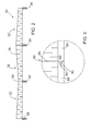
- Figure 2 is a side elevational view of the roof structure of Figure 1 ;
- Figure 3 is an enlarged portion of Figure 2 ;
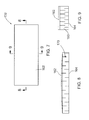
- Figure 4 is a perspective view of a structural insulating panel forming part of the flat roof structure of Figure 1 ;
- Figure 5 is a cross-sectional view of Figure 4 taken along line 5-5;
- Figure 6 is a cross-sectional view of Figure 4 taken along line 6-6;
- Figure 7 is a top plan view of an alternative structural insulating panel for use in a flat roof structure
- Figure 8 is a cross-sectional view of Figure 7 taken along line 8-8;
- Figure 9 is a cross-sectional view of Figure 7 taken along line 9-9;
- Figure 10 is a top plan view of yet another structural insulating panel for use in a flat roof structure
- Figure 11 is a cross-sectional view of Figure 10 taken along line 11-11;
- Figure 12 is a cross-sectional view of Figure 10 taken along line 12-12;
- Figure 13 is an enlarged side elevational view of a portion of adjacent structural insulating panels showing an alternative joint
- Figure 14 is an enlarged side elevational view of a portion of adjacent structural insulating panels showing yet another joint.
- the flat roof structure 30 comprises a plurality of abutting structural insulating panels 32 arranged in an array.
- the array comprises six (6) rows and three (3) columns of panels 32.
- the 6 x 3 array of panels 32 is shown for illustrative purposes only.
- the dimensions of the panel array can vary significantly depending on the overall size of the flat roof structure 30 and the dimensions of the individual panels 32 in the array.
- the longitudinal dimension of each panel 32 is selected so that each structural insulating panel 32 spans at least one pair of adjacent rafters 34.
- each structural insulating panel 32 will have a lengthwise dimension in the range of from about eight (8) feet to about twenty (20) feet and a widthwise dimension equal to about four (4) feet.
- Suitable fasteners such as screws or nails are used to secure the structural insulating panels 32 to the rafters 34.
- the upper surfaces 36 of the structural insulating panels 32 define the decking 38 of the flat roof structure 30 on which roofing (not shown) is applied.
- the structural insulating panels 32 are configured so that the decking 38 is pitched in multiple dimensions thereby to promote drainage towards the outer peripheral edges of the flat roof structure 30. The pitch in each dimension is typically selected so that it does not exceed 1/12".
- the structural insulating panels 32 in column C1, rows R1 to R3 and in column C3, rows R1 to R3 are configured so that the flat roof structure 30 slopes linearly downwardly to the right as indicated by arrows 40 and slopes linearly downwardly from its central longitudinal axis 42 towards its peripheral side edge 44 as indicated by arrows 46.
- the structural insulating panels 32 in column C1, rows R4 to R6 and in column C3, rows R4 to R6 are configured so that the flat roof structure 30 slopes linearly downwardly to the right as indicated by arrows 40 and slopes linearly downwardly from its longitudinal axis 42 towards its peripheral side edge 48 as indicated by arrows 50.
- the structural insulating panels 32 in column C2, rows R1 to R3 are configured so that the flat roof structure 30 slopes linearly downwardly to the left as indicated by arrow 52 and slopes linearly downwardly from its longitudinal axis 42 towards its peripheral side edge 44 as indicated by arrow 46.
- the structural insulating panels 32 in column C2, rows R4 to R6 are configured so that the flat roof structure 30 slopes linearly downwardly to the left as indicated by arrow 52 and slopes linearly downwardly from its longitudinal axis 42 towards its peripheral side edge 48 as indicated by arrow 50.
- structural insulating panel 32 comprises an intermediate layer 60 sandwiched between and bonded to upper and lower structural layers 62 and 64 respectively by suitable adhesive.
- the intermediate layer 60 is formed of expanded polystyrene (EPS) foam and comprises a core 70 typically having a thickness in the range of from about 1" to about 16", a top skin 72 on the core 70 having a thickness of about 7/16" and a bottom skin 74 on the core 70 having a thickness of about 5/8".
- the upper and lower structural layers 62 and 64 are formed of a suitable structural material such as for example plywood and have a thickness generally in the range of from about 1/8" to about 11 ⁇ 8". The thicknesses of the upper and lower structural layers 62 and 64 are selected to give the flat roof structure 30 its desired fire rating.
- the core 70 varies in thickness to give the structural insulating panel 32 its desired pitch.
- the upper structural layer 62 which overlies the top skin 72 of the intermediate layer 60 conforms to the orientation of the intermediate layer and thus, provides the sloped upper decking surface onto which the roofing is applied.
- One minor side of the lower structural layer 64 has a groove 80 formed therein and the opposite minor side of the lower structural layer 64 has a tongue 82 formed thereon.
- the groove 80 is shaped to receive a tongue formed on an adjacent structural insulating panel 32 and the tongue 82 is shaped to be inserted into the groove formed in another adjacent structural insulating panel 32.
- one major side of the lower structural layer may be provided with a groove and the opposite major side of the lower structural layer may be provided with a tongue.
- one of the seams 90 between two adjacent structural insulating panels 32 is shown.
- the tongue 82 on the lower structural layer 64 of one structural insulating panel is received in the groove 80 formed in the lower structural layer 64 of the other structural insulating panel.
- Adhesive caulking 92 is applied to the tongue 82 and/or groove 80 prior to insertion of the tongue into the groove to secure the lower structural layers of the adjacent structural insulating panels 32 together.
- a sealant 94 such as for example, a foam seal or sill seal gasket, is used to fill any gaps between the intermediate layers 60 and upper structural layers 62 of the adjacent structural insulating panels at the seam 90.
- the structural insulating panels 32 of the flat roof structure 30 are configured so that the flat roof structure 30 slopes linearly downward in two different directions.
- a structural insulating panel configuration can be used in flat roof structures 30 to promote drainage.
- FIGs 7 to 9 another embodiment of a structural insulating panel for use in a flat roof structure is shown and is generally identified by reference numeral 132. Similar to the structural insulating panel 32, structural insulating panel 132 also comprises an intermediate EPS layer 160 sandwiched between upper and lower structural layers 162 and 164 respectively. In this embodiment, rather than sloping linearly downwardly in two different directions, the core 170 of the intermediate layer 160 has a parabolic shape and thus, curves downwardly from its center in all directions towards the edges of the intermediate layer.
- Figures 10 to 12 show yet another embodiment of a structural insulating panel 232 for use in a flat roof structure. Similar to the structural insulating panels 32 and 132, structural insulating panel 232 comprises an intermediate EPS layer 260 sandwiched between upper and lower structural layers 262 and 264 respectively. In this embodiment, the core 270 of the intermediate layer 260 slopes linearly downwardly in only one direction.
- FIG. 13 shows adjacent structural insulating panels 32 interconnected via an overlap joint
- Figure 14 shows adjacent structural insulting panels interconnected via a butt spline joint.
- the upper and lower structural layers 62 and 64 are described as being formed of plywood. Those of skill in the art will appreciate that the upper and lower structural layers may be formed of other suitable structural material such as for example OSB, metal sheet, fire resistant board etc. Also, the intermediate layer 60 need not be formed of EPS. Other foam material such as for example urethane foam, polyurethane foam, isocyanurate foam etc. or other suitable non-foam material such as for example honeycomb board may be used.
- structural insulating panels that provide pitched upper decking surfaces are described and illustrated above, those of skill in the art will appreciate that the structural insulating panels may take on other orientations to promote drainage. Of course, if desired the structural insulating panels can be used on wall structures for structural and/or decorative purposes.
Abstract
Description
- The present invention relates generally to building structure and in particular, to a structural insulating panel and flat roof structure employing the same.
- Historically, flat or horizontal roofs on commercial and residential buildings have been common in warmer, drier climates where water accumulation as a result of precipitation is not a problem. More recently, flat roofs have become popular in cooler, wetter climates. Unlike sloped roofs, flat roofs have ineffective drainage characteristics making them prone to leakage problems. In wetter climates, to deal with this drainage issue, complex water proofing is typically required in flat roofs. In commercial buildings, drains are sometimes provided in the flat roofs to collect rainwater and melting snow and direct the water off of the roofs.
- For example,
U.S. Patent No. 5,144,782 to Paquette et al. discloses a draining system for water which may collect between the upper and lower membranes of a flat insulated roof. Insulating panels located between the upper and lower membranes are provided at both their upper and lower faces with a network of intersecting grooves. The networks of grooves communicate with each other through passages made through the insulating panels or constituted at the insulating panel joints. The grooves and passages provide drainage channels for any water that has seeped under the upper membrane as a result of perforations in the upper membrane. A lower drain is sealed to and opens above the lower membrane to drain water collected by the drainage channels. Drainage of the water helps to prevent deterioration of the insulating panels and water accumulation which may provoke overload problems. - Although such drainage structures are effective in removing water from flat roofs, they add significant complexity to the building structures and hence, increase costs making them unsuitable in many environments. As will be appreciated, alternative techniques to improve drainage in flat roofs are desired.
- It is therefore an object of the present invention at least to provide a novel structural insulating panel and roof structure employing the same.
- Accordingly, in one aspect there is provided a structural insulating panel for use in a flat roof structure comprising upper and lower structural layers and an intermediate layer between the upper and lower structural layers, the intermediate layer being shaped such that the upper structural layer is sloped relative to a horizontal plane when the structural insulating panel is installed in a flat roof structure.
- In one embodiment, the intermediate layer is shaped such that the upper structural layer is sloped in multiple dimensions relative to the horizontal plane. The upper structural layer may slope generally linearly downwardly in generally orthogonal directions or may curve downwardly in different directions. In another embodiment, the intermediate layer is shaped such that the upper structural layer slopes generally linearly downwardly in a single direction.
- In one form, the intermediate layer is sandwiched directly between the upper and lower structural layers. The thicknesses of the upper and lower structural layers are selected to give the structural insulating panel a desired fire rating. Each of the upper and lower structural layers may have a thickness in the range from about 1/8" to about 1⅛". The intermediate layer may have a minimum thickness of about 1" and a maximum thickness of about 16".
- According to another aspect there is provided a flat roof structure comprising a plurality of abutting structural insulating panels, each structural insulating panel spanning at least a pair of adjacent rafters of the flat roof structure and defining an upper decking surface on which roofing is applied, the structural insulating panels being configured such that the upper decking surface is non-horizontal thereby to promote drainage.
- The structural insulating panels in one form are arranged at least one of end-to-end and side-to-side with adjacent structural panels carrying mating formations. Sealant seals seams between the adjacent structural insulating panels.
- According to yet another aspect there is provided a structural insulating panel comprising an intermediate layer sandwiched between and adhered to first and second structural layers, the intermediate layer varying in thickness such that the first and second structural layers are non-parallel.
- Embodiments will now be described more fully with reference to the accompanying drawings in which:
-
Figure 1 is a top plan view of a flat roof structure employing structural insulating panels; -
Figure 2 is a side elevational view of the roof structure ofFigure 1 ; -
Figure 3 is an enlarged portion ofFigure 2 ; -
Figure 4 is a perspective view of a structural insulating panel forming part of the flat roof structure ofFigure 1 ; -
Figure 5 is a cross-sectional view ofFigure 4 taken along line 5-5; -
Figure 6 is a cross-sectional view ofFigure 4 taken along line 6-6; -
Figure 7 is a top plan view of an alternative structural insulating panel for use in a flat roof structure; -
Figure 8 is a cross-sectional view ofFigure 7 taken along line 8-8; -
Figure 9 is a cross-sectional view ofFigure 7 taken along line 9-9; -
Figure 10 is a top plan view of yet another structural insulating panel for use in a flat roof structure; -
Figure 11 is a cross-sectional view ofFigure 10 taken along line 11-11; -
Figure 12 is a cross-sectional view ofFigure 10 taken along line 12-12; -
Figure 13 is an enlarged side elevational view of a portion of adjacent structural insulating panels showing an alternative joint; and -
Figure 14 is an enlarged side elevational view of a portion of adjacent structural insulating panels showing yet another joint. - Turning now to
Figures 1 to 3 , a flat roof structure is shown and is generally identified byreference numeral 30. Theflat roof structure 30 comprises a plurality of abutting structuralinsulating panels 32 arranged in an array. In this embodiment, the array comprises six (6) rows and three (3) columns ofpanels 32. Those of skill in the art will appreciate that the 6 x 3 array ofpanels 32 is shown for illustrative purposes only. The dimensions of the panel array can vary significantly depending on the overall size of theflat roof structure 30 and the dimensions of theindividual panels 32 in the array. The longitudinal dimension of eachpanel 32 is selected so that eachstructural insulating panel 32 spans at least one pair ofadjacent rafters 34. Typically, eachstructural insulating panel 32 will have a lengthwise dimension in the range of from about eight (8) feet to about twenty (20) feet and a widthwise dimension equal to about four (4) feet. Suitable fasteners (not shown) such as screws or nails are used to secure thestructural insulating panels 32 to therafters 34. - The
upper surfaces 36 of thestructural insulating panels 32 define thedecking 38 of theflat roof structure 30 on which roofing (not shown) is applied. Thestructural insulating panels 32 are configured so that thedecking 38 is pitched in multiple dimensions thereby to promote drainage towards the outer peripheral edges of theflat roof structure 30. The pitch in each dimension is typically selected so that it does not exceed 1/12". In the embodiment ofFigure 1 , the structuralinsulating panels 32 in column C1, rows R1 to R3 and in column C3, rows R1 to R3 are configured so that theflat roof structure 30 slopes linearly downwardly to the right as indicated byarrows 40 and slopes linearly downwardly from its centrallongitudinal axis 42 towards itsperipheral side edge 44 as indicated byarrows 46. Thestructural insulating panels 32 in column C1, rows R4 to R6 and in column C3, rows R4 to R6 are configured so that theflat roof structure 30 slopes linearly downwardly to the right as indicated byarrows 40 and slopes linearly downwardly from itslongitudinal axis 42 towards itsperipheral side edge 48 as indicated byarrows 50. Thestructural insulating panels 32 in column C2, rows R1 to R3 are configured so that theflat roof structure 30 slopes linearly downwardly to the left as indicated byarrow 52 and slopes linearly downwardly from itslongitudinal axis 42 towards itsperipheral side edge 44 as indicated byarrow 46. Thestructural insulating panels 32 in column C2, rows R4 to R6 are configured so that theflat roof structure 30 slopes linearly downwardly to the left as indicated byarrow 52 and slopes linearly downwardly from itslongitudinal axis 42 towards itsperipheral side edge 48 as indicated byarrow 50. - Turning now to
Figures 4 to 6 , one of structuralinsulating panels 32 is better illustrated. As can be seen,structural insulating panel 32 comprises anintermediate layer 60 sandwiched between and bonded to upper and lowerstructural layers intermediate layer 60 is formed of expanded polystyrene (EPS) foam and comprises acore 70 typically having a thickness in the range of from about 1" to about 16", atop skin 72 on thecore 70 having a thickness of about 7/16" and abottom skin 74 on thecore 70 having a thickness of about 5/8". The upper and lowerstructural layers structural layers flat roof structure 30 its desired fire rating. - The
core 70 varies in thickness to give the structural insulatingpanel 32 its desired pitch. As a result, the upperstructural layer 62 which overlies thetop skin 72 of theintermediate layer 60 conforms to the orientation of the intermediate layer and thus, provides the sloped upper decking surface onto which the roofing is applied. One minor side of the lowerstructural layer 64 has agroove 80 formed therein and the opposite minor side of the lowerstructural layer 64 has atongue 82 formed thereon. Thegroove 80 is shaped to receive a tongue formed on an adjacent structural insulatingpanel 32 and thetongue 82 is shaped to be inserted into the groove formed in another adjacent structural insulatingpanel 32. Similarly if desired, one major side of the lower structural layer may be provided with a groove and the opposite major side of the lower structural layer may be provided with a tongue. - Looking back to
Figure 3 , one of theseams 90 between two adjacent structural insulatingpanels 32 is shown. As can be seen, thetongue 82 on the lowerstructural layer 64 of one structural insulating panel is received in thegroove 80 formed in the lowerstructural layer 64 of the other structural insulating panel.Adhesive caulking 92 is applied to thetongue 82 and/or groove 80 prior to insertion of the tongue into the groove to secure the lower structural layers of the adjacent structural insulatingpanels 32 together. Asealant 94 such as for example, a foam seal or sill seal gasket, is used to fill any gaps between theintermediate layers 60 and upperstructural layers 62 of the adjacent structural insulating panels at theseam 90. - In the above embodiment, the structural insulating
panels 32 of theflat roof structure 30 are configured so that theflat roof structure 30 slopes linearly downward in two different directions. Those of skill in the art will appreciate however, that other structural insulating panel configurations can be used inflat roof structures 30 to promote drainage. For example, turning now toFigures 7 to 9 , another embodiment of a structural insulating panel for use in a flat roof structure is shown and is generally identified byreference numeral 132. Similar to the structural insulatingpanel 32, structural insulatingpanel 132 also comprises anintermediate EPS layer 160 sandwiched between upper and lowerstructural layers core 170 of theintermediate layer 160 has a parabolic shape and thus, curves downwardly from its center in all directions towards the edges of the intermediate layer. -
Figures 10 to 12 show yet another embodiment of a structuralinsulating panel 232 for use in a flat roof structure. Similar to the structural insulatingpanels panel 232 comprises anintermediate EPS layer 260 sandwiched between upper and lowerstructural layers core 270 of theintermediate layer 260 slopes linearly downwardly in only one direction. - Although the embodiments described and shown above show adjacent structural insulating
panels 32 as comprising mating formations in the form of tongues and grooves, those of skill in the art will appreciate that alternative joints between adjacent structural insulating panels can be used. For example,Figure 13 shows adjacent structural insulatingpanels 32 interconnected via an overlap joint andFigure 14 shows adjacent structural insulting panels interconnected via a butt spline joint. - Although dimensions for the structural insulating panels and components therefor, are provided above, those of skill in the art will appreciate that the dimensional information is exemplary. Depending on the environment in which the structural insulating panels are being deployed, the overall dimensions of the structural insulating panels and the dimensions of the panel components may vary from those discussed above.
- In the embodiments described above, the upper and lower
structural layers intermediate layer 60 need not be formed of EPS. Other foam material such as for example urethane foam, polyurethane foam, isocyanurate foam etc. or other suitable non-foam material such as for example honeycomb board may be used. - While particular examples of structural insulating panels that provide pitched upper decking surfaces are described and illustrated above, those of skill in the art will appreciate that the structural insulating panels may take on other orientations to promote drainage. Of course, if desired the structural insulating panels can be used on wall structures for structural and/or decorative purposes.
- Although embodiments have been described above with reference to the drawings, those of skill in the art will appreciate that variations and modifications may be made without departing from the spirit and scope thereof as defined by the appended claims.
Claims (15)
- A structural insulating panel for use in a flat roof structure comprising:upper and lower structural layers; andan intermediate layer between said upper and lower structural layers, said intermediate layer being shaped such that said upper structural layer is sloped relative to a generally horizontal plane when said structural insulating panel is installed in a flat roof structure.
- A structural insulating panel according to claim 1 wherein said intermediate layer is shaped such that the upper structural layer is sloped in multiple dimensions relative to said horizontal plane.
- A structural insulating panel according to claim 2 wherein said intermediate layer is shaped such that the upper structural layer slopes generally linearly downwardly in two generally orthogonal directions.
- A structural insulating panel according to claim 2 wherein said intermediate layer is shaped such that the upper structural layer curves downwardly in different directions.
- A structural insulating panel according to claim 4 wherein an upper surface of said intermediate layer on which said upper structural layer is disposed, has a generally parabolic shape.
- A structural insulating panel according to claim 1 wherein said intermediate layer is shaped such that the upper structural layer slopes generally linearly downwardly in a single direction.
- A structural insulating panel according to any one of claims 1 to 6 wherein said intermediate layer is formed of foam material and preferably from one of expanded polystyrene foam, urethane foam, polyurethane foam and isocyanurate foam.
- A structural insulating panel according to any one of claims 1 to 7 wherein said intermediate layer is sandwiched directly between said upper and lower structural layers.
- A structural insulating panel according to claim 8 wherein thicknesses of said upper and lower structural layers are selected to give said structural insulating panel a desired fire rating and preferably are formed of material selected from plywood, OSB, metal sheet or other suitable material.
- A flat roof structure comprising:a plurality of abutting structural insulating panels, each structural insulating panel spanning at least a pair of adjacent rafters of said flat roof structure and defining an upper decking surface on which roofing is applied, said structural insulating panels being configured such that said upper decking surface is non-horizontal thereby to promote drainage.
- A flat roof structure according to claim 10 wherein said structural insulating panels are arranged at least one of end-to-end and side-to-side.
- A flat roof structure according to claim 10 or 11 wherein adjacent structural insulating panels carry mating formations such as tongues and grooves.
- A flat roof structure according to any one of claims 10 to 13 further comprising sealant to seal seams between adjacent structural insulating panels.
- A flat roof structure according to any one of claims 10 to 13 wherein each structural insulating panel is of the type according to any one of claims 1 to 9.
- A structural insulating panel comprising:an intermediate layer sandwiched between and adhered to first and second structural layers, said intermediate layer varying in thickness such that said first and second structural layers are non-parallel.
Applications Claiming Priority (1)
| Application Number | Priority Date | Filing Date | Title |
|---|---|---|---|
| US12/118,011 US20090277113A1 (en) | 2008-05-09 | 2008-05-09 | Structural insulating panel and flat roof structure employing same |
Publications (1)
| Publication Number | Publication Date |
|---|---|
| EP2116664A1 true EP2116664A1 (en) | 2009-11-11 |
Family
ID=40886956
Family Applications (1)
| Application Number | Title | Priority Date | Filing Date |
|---|---|---|---|
| EP09159733A Withdrawn EP2116664A1 (en) | 2008-05-09 | 2009-05-08 | Structural insulating panel and flat roof structure employing same |
Country Status (4)
| Country | Link |
|---|---|
| US (1) | US20090277113A1 (en) |
| EP (1) | EP2116664A1 (en) |
| CN (1) | CN101603356A (en) |
| CA (1) | CA2665652C (en) |
Cited By (2)
| Publication number | Priority date | Publication date | Assignee | Title |
|---|---|---|---|---|
| WO2013172775A1 (en) * | 2012-05-16 | 2013-11-21 | Cirkelfallet Ab | Surface covering system and method for producing such a system |
| CN112593662A (en) * | 2020-12-08 | 2021-04-02 | 湖南鸿云钢模科技有限公司 | Floor type awning structure for steel structure house construction |
Families Citing this family (18)
| Publication number | Priority date | Publication date | Assignee | Title |
|---|---|---|---|---|
| US20090313931A1 (en) * | 2008-06-24 | 2009-12-24 | Porter William H | Multilayered structural insulated panel |
| US20110072736A1 (en) * | 2009-09-30 | 2011-03-31 | Atlas Roofing Corporation | Drainage members for flat roofs and methods of making same |
| US8534018B2 (en) * | 2010-08-24 | 2013-09-17 | James Walker | Ventilated structural panels and method of construction with ventilated structural panels |
| US8490355B2 (en) * | 2010-08-24 | 2013-07-23 | James Walker | Ventilated structural panels and method of construction with ventilated structural panels |
| US9604428B2 (en) | 2010-08-24 | 2017-03-28 | James Walker | Ventilated structural panels and method of construction with ventilated structural panels |
| US9091049B2 (en) | 2010-08-24 | 2015-07-28 | James Walker | Ventilated structural panels and method of construction with ventilated structural panels |
| US9050766B2 (en) | 2013-03-01 | 2015-06-09 | James Walker | Variations and methods of producing ventilated structural panels |
| US8365487B2 (en) * | 2010-11-23 | 2013-02-05 | Hunter Panels Llc | Roof sump structure |
| MX336399B (en) * | 2011-04-06 | 2016-01-15 | Bluescope Buildings North America Inc | Bridging thermal block system and method. |
| JP5522150B2 (en) * | 2011-11-14 | 2014-06-18 | ダイキン工業株式会社 | Refrigeration equipment outdoor unit |
| US8950140B1 (en) * | 2013-08-12 | 2015-02-10 | Dimensional Tile Backer, LLC | Dimensional tile backing |
| US9328516B2 (en) * | 2013-10-14 | 2016-05-03 | Division 8 Products, Inc. | Trellis with internal drainage system |
| SE540102C2 (en) * | 2014-09-17 | 2018-03-27 | Grade Group As | Surface coating systems and methods of making such a system |
| CN104695632A (en) * | 2015-03-18 | 2015-06-10 | 德州市好宜居木结构有限公司 | Integrated module roof system |
| US11118798B2 (en) * | 2019-03-08 | 2021-09-14 | Johnson Controls Technology Company | Composite roof structure for air handling units |
| US11685140B2 (en) * | 2020-06-05 | 2023-06-27 | Johns Manville | Non-wicking underlayment board |
| US11773586B2 (en) * | 2020-06-05 | 2023-10-03 | Johns Manville | Non-wicking underlayment board |
| CN113047535B (en) * | 2021-03-29 | 2022-09-02 | 北京天润建设有限公司 | Roof elevation device and method |
Citations (8)
| Publication number | Priority date | Publication date | Assignee | Title |
|---|---|---|---|---|
| GB966931A (en) | 1961-04-05 | 1964-08-19 | Ruberoidwerke Ag | Improvements in or relating to roof constructions |
| US4587164A (en) * | 1985-04-29 | 1986-05-06 | The Dow Chemical Company | Roof deck composite panels |
| DE8807466U1 (en) * | 1988-06-08 | 1988-08-18 | Iso Bouw B.V., Someren, Nl | |
| EP0399346A1 (en) * | 1989-05-26 | 1990-11-28 | PHILIPPINE GMBH & CO. DÄMMSTOFFSYSTEME KG | Method for manufacturing insulating boards for inclined roofs and cutting device for the realisation of the method |
| DE9010537U1 (en) * | 1990-07-16 | 1991-11-14 | Algostat Gmbh & Co. Kg, 3100 Celle, De | |
| US5144782A (en) | 1990-08-15 | 1992-09-08 | Paquette Jean Paul | Double-level drainage system for flat roofs |
| DE4441646A1 (en) | 1994-11-23 | 1996-06-05 | Lux Kg | Method of assembling cover e.g. floor tiles for balcony, terrace etc. |
| WO2008083970A1 (en) * | 2007-01-12 | 2008-07-17 | Deutsche Rockwool Mineralwoll Gmbh & Co. Ohg | Sloping roof system and insulating board for sloping roof systems |
Family Cites Families (11)
| Publication number | Priority date | Publication date | Assignee | Title |
|---|---|---|---|---|
| US3138898A (en) * | 1957-08-14 | 1964-06-30 | Johns Manville | Joint for insulating board roof plank |
| US3209502A (en) * | 1961-06-07 | 1965-10-05 | Allied Chem | Insulating roof deck structure |
| US3349525A (en) * | 1966-01-14 | 1967-10-31 | Koppers Co Inc | Interacting laminar shell structural component |
| US4642950A (en) * | 1979-03-16 | 1987-02-17 | Kelly Thomas L | Reroofing with sloping plateau forming insulation |
| US4503644A (en) * | 1983-05-09 | 1985-03-12 | Coutu Sr Walter H | Roof construction |
| US4907383A (en) * | 1987-04-27 | 1990-03-13 | Winter Amos G Iv | Bowed roof structure, structure panel and method for using same |
| CN2115370U (en) * | 1991-12-25 | 1992-09-09 | 黑龙江省低温建筑科学研究所 | Energy-saving roof boarding |
| US5590501A (en) * | 1993-12-23 | 1997-01-07 | Styro-Stop, Inc. | Insulation barrier and a method of making an insulation barrier |
| US6415570B1 (en) * | 2000-09-01 | 2002-07-09 | Roofers Mart Of Wisconsin, Inc. | Modular roofing system and assembly |
| US7040067B2 (en) * | 2004-08-13 | 2006-05-09 | Associated Materials, Inc. | Siding panel with insulated backing panel |
| CA2482878A1 (en) * | 2004-09-29 | 2006-03-29 | Denis Lapointe | Insulating roofing system for flat roofs |
-
2008
- 2008-05-09 US US12/118,011 patent/US20090277113A1/en not_active Abandoned
-
2009
- 2009-05-08 CA CA2665652A patent/CA2665652C/en active Active
- 2009-05-08 EP EP09159733A patent/EP2116664A1/en not_active Withdrawn
- 2009-05-11 CN CNA2009101497932A patent/CN101603356A/en active Pending
Patent Citations (8)
| Publication number | Priority date | Publication date | Assignee | Title |
|---|---|---|---|---|
| GB966931A (en) | 1961-04-05 | 1964-08-19 | Ruberoidwerke Ag | Improvements in or relating to roof constructions |
| US4587164A (en) * | 1985-04-29 | 1986-05-06 | The Dow Chemical Company | Roof deck composite panels |
| DE8807466U1 (en) * | 1988-06-08 | 1988-08-18 | Iso Bouw B.V., Someren, Nl | |
| EP0399346A1 (en) * | 1989-05-26 | 1990-11-28 | PHILIPPINE GMBH & CO. DÄMMSTOFFSYSTEME KG | Method for manufacturing insulating boards for inclined roofs and cutting device for the realisation of the method |
| DE9010537U1 (en) * | 1990-07-16 | 1991-11-14 | Algostat Gmbh & Co. Kg, 3100 Celle, De | |
| US5144782A (en) | 1990-08-15 | 1992-09-08 | Paquette Jean Paul | Double-level drainage system for flat roofs |
| DE4441646A1 (en) | 1994-11-23 | 1996-06-05 | Lux Kg | Method of assembling cover e.g. floor tiles for balcony, terrace etc. |
| WO2008083970A1 (en) * | 2007-01-12 | 2008-07-17 | Deutsche Rockwool Mineralwoll Gmbh & Co. Ohg | Sloping roof system and insulating board for sloping roof systems |
Cited By (5)
| Publication number | Priority date | Publication date | Assignee | Title |
|---|---|---|---|---|
| WO2013172775A1 (en) * | 2012-05-16 | 2013-11-21 | Cirkelfallet Ab | Surface covering system and method for producing such a system |
| US9303411B2 (en) | 2012-05-16 | 2016-04-05 | Grade Group As | Surface covering system and method for producing such a system |
| EA032677B1 (en) * | 2012-05-16 | 2019-07-31 | Грейд Груп Ас | System for drainage of fluids from substantially flat surfaces intended for covering a floor or a roof |
| CN112593662A (en) * | 2020-12-08 | 2021-04-02 | 湖南鸿云钢模科技有限公司 | Floor type awning structure for steel structure house construction |
| CN112593662B (en) * | 2020-12-08 | 2022-11-11 | 中建二局阳光智造有限公司 | Floor type awning structure for steel structure house construction |
Also Published As
| Publication number | Publication date |
|---|---|
| CA2665652A1 (en) | 2009-11-09 |
| CN101603356A (en) | 2009-12-16 |
| CA2665652C (en) | 2016-10-18 |
| US20090277113A1 (en) | 2009-11-12 |
Similar Documents
| Publication | Publication Date | Title |
|---|---|---|
| CA2665652C (en) | Structural insulating panel and flat roof structure employing same | |
| US6415580B2 (en) | Insulated roof panel | |
| CA2796095A1 (en) | Ventilated structural panels and method of construction with ventilated structural panels | |
| US6279293B1 (en) | Insulated roof panel | |
| US20060101777A1 (en) | Insulating roofing system for flat roofs | |
| US6952901B2 (en) | Panel mounted shingles assembly with ventilating screen | |
| AU2003288482B2 (en) | A composite roof panel | |
| US11608640B2 (en) | Panelized roofing system | |
| JP3540911B2 (en) | Roof panel connection structure | |
| JP4028881B2 (en) | Roof panel and breathable roof structure | |
| CA2792344A1 (en) | Ventilated structural panels and method of construction with ventilated structural panels | |
| JP2740311B2 (en) | Roof panel connection structure | |
| JP2943907B2 (en) | Insulation base material for building exterior | |
| CZ20013919A3 (en) | Insulating element and use thereof | |
| JP2818928B2 (en) | Roof structure | |
| JP2630852B2 (en) | Face plate for building | |
| EP0451083B1 (en) | Roofing and roofing units for use therein | |
| JP2020143500A (en) | Fitting type roof material and joint structure of fitting type roof material | |
| EP0736641A1 (en) | A roof and/or wall covering construction, as well as a panel for such a construction | |
| EP1312726A1 (en) | A panel for external covering of buildings | |
| JPH06322847A (en) | Waterproof structure of vertical outer wall joint | |
| GB2409213A (en) | Breathable insulation material; preventing condensation in insulated spaces | |
| IE84565B1 (en) | A composite roof panel | |
| JPH0216241A (en) | Drainage structure for tiled roof | |
| JPH04302644A (en) | Roof panel |
Legal Events
| Date | Code | Title | Description |
|---|---|---|---|
| PUAI | Public reference made under article 153(3) epc to a published international application that has entered the european phase |
Free format text: ORIGINAL CODE: 0009012 |
|
| AK | Designated contracting states |
Kind code of ref document: A1 Designated state(s): AT BE BG CH CY CZ DE DK EE ES FI FR GB GR HR HU IE IS IT LI LT LU LV MC MK MT NL NO PL PT RO SE SI SK TR |
|
| 17P | Request for examination filed |
Effective date: 20100511 |
|
| 17Q | First examination report despatched |
Effective date: 20100708 |
|
| GRAP | Despatch of communication of intention to grant a patent |
Free format text: ORIGINAL CODE: EPIDOSNIGR1 |
|
| INTG | Intention to grant announced |
Effective date: 20140103 |
|
| STAA | Information on the status of an ep patent application or granted ep patent |
Free format text: STATUS: THE APPLICATION IS DEEMED TO BE WITHDRAWN |
|
| 18D | Application deemed to be withdrawn |
Effective date: 20140514 |