EP2116276A2 - Öffentlich zugänglicher Defibrillator - Google Patents
Öffentlich zugänglicher Defibrillator Download PDFInfo
- Publication number
- EP2116276A2 EP2116276A2 EP09168921A EP09168921A EP2116276A2 EP 2116276 A2 EP2116276 A2 EP 2116276A2 EP 09168921 A EP09168921 A EP 09168921A EP 09168921 A EP09168921 A EP 09168921A EP 2116276 A2 EP2116276 A2 EP 2116276A2
- Authority
- EP
- European Patent Office
- Prior art keywords
- patient
- external defibrillator
- defibrillator
- controller
- therapy
- Prior art date
- Legal status (The legal status is an assumption and is not a legal conclusion. Google has not performed a legal analysis and makes no representation as to the accuracy of the status listed.)
- Withdrawn
Links
Images

Classifications
-
- A—HUMAN NECESSITIES
- A61—MEDICAL OR VETERINARY SCIENCE; HYGIENE
- A61N—ELECTROTHERAPY; MAGNETOTHERAPY; RADIATION THERAPY; ULTRASOUND THERAPY
- A61N1/00—Electrotherapy; Circuits therefor
- A61N1/18—Applying electric currents by contact electrodes
- A61N1/32—Applying electric currents by contact electrodes alternating or intermittent currents
- A61N1/38—Applying electric currents by contact electrodes alternating or intermittent currents for producing shock effects
- A61N1/39—Heart defibrillators
- A61N1/3904—External heart defibrillators [EHD]
Definitions
- This invention pertains to an external defibrillator adapted to provide therapy selectively to patients suffering from sudden acute cardiac arrest. More particularly, the present invention pertains to an external defibrillator which is constructed and arranged to operate substantially automatically once it is positioned on the patient. The defibrillator rapidly determines the status of the patient, makes a decision on whether therapy is indicated, and, if necessary, applies such therapy until either its operation is discontinued externally or sinus rhythm has been achieved.
- SCA Sudden Cardiac Arrest or SCA in a patient refers to a condition characterized by a loss of effective pumping action in the heart and is generally caused by an arrhythmia. SCA results in an abrupt cessation of blood circulation to the vital organs, and once it occurs, unless the patient's heart is reverted rapidly to a sinus rhythm, death will occur. In fact SCA is considered to be the leading cause of death in the United States and throughout the world.
- Arrhythmias which cause SCA include ventricular tachycardia and ventricular fibrillation.
- Ventricular tachycardia is characterized by electrical disturbances which cause a dangerously high cardiac rate and may lead to ventricular fibrillation.
- Ventricular fibrillation refers to a state where cardiac electrical activity is completely disorganized and the heart is quivering. During ventricular fibrillation, the heart does not pump blood, and no beats can be detected.
- Arrhythmias may be detected from the patient's electrocardiogram (ECG), blood pressure, blood oxygenation level and other similar physiological parameters. Because the signals indicative of these parameters can be very complex, various algorithms are used to analyze these parameters to detect and classify an arrhythmia. Once detected, the arrhythmia can be eliminated by using antitachycardia therapy consisting of electrical stimulation. Two kinds of devices are presently available to provide antitachyarrhythmia therapy: internal or implanted cardioverter defibrillators (ICDs), and external defibrillators.
- ICDs implanted cardioverter defibrillators
- ICDs have been known since the early 1980s. These devices are implanted in the patient and include electrodes extending to the cardiac chambers to sense intrinsic cardiac activity and to provide stimulation signals. The intrinsic signals sensed in the cardiac chambers are used to classify the condition of the heart, and if a tachyarrhythmia is detected,'then either cardioversion pacing pulses or defibrillation shocks are applied.
- a clinician examines the patient and, after implantation, programs a plurality of parameters into the ICD which are used by a processor to classify the condition of the patient and determine the characteristics of the stimulation signals to be applied. Frequently these parameters are selected after the patient's heart rate is increased either naturally, with exercise, or with drugs. It is advisable to re-program these parameters as the condition of the patient changes over time.
- External defibrillators capable of providing defibrillation shocks or other types of therapy are also well known.
- Current external defibrillators must be operated manually by a trained professional such as an emergency medical technician, paramedic, firefighter, or police officer, etc.
- Existing external defibrillators do not monitor cardiac activity before a sudden cardiac arrest episode, and accordingly, the professional must examine the patient and determine his condition first, before any therapy is provided.
- the existing external defibrillators cannot be used by a layperson.
- An external defibrillator described in commonly assigned U.S. Patent No. 5,474,574 and incorporated herein by reference includes an ECG sensor and requires several parameters to be programmed by a clinician before it can be used properly. Some of the programmable parameters pertain to the sensitivity of the ECG sensor required to detect ECGs reliably. Other parameters pertain to the size, number and duration of the shocks to be applied by the device. Since these parameters must be programmed separately for each patient, by the time this defibrillator is ready to be used, it is configured to a specific patient and cannot be used for a different patient without first reprogramming its parameters.
- an objective of the present invention is to provide an external defibrillator which can be distributed and placed at public places which can be used effectively by a person with no special medical training.
- a further objective is to provide an external defibrillator able to monitor a patient and determine automatically if a patient is in need of therapy.
- a further objective is to provide an external defibrillator capable of providing cardiac therapy without requiring any information about the patient receiving it.
- Yet another objective is to provide an external defibrillator which has several modes of operation so that it can be used for different purposes.
- an external defibrillator constructed in accordance with this invention includes a sensing circuit used to sense physiological signals indicative of cardiac activity, a therapy delivery circuit that generates pacing or shock pulses, and a controller that is used to operate the defibrillator automatically.
- Signals indicative of intrinsic cardiac activity including R-waves and ventricular fibrillation, for example, are determined using generic criteria rather than patient-specific programming parameters.
- the pulses applied to the patient to effect therapy have characteristics which are derived from general statistical data and are not patient specific.
- the defibrillator recognizes a life threatening cardiac condition and can apply appropriate therapy without any human input or intervention.
- the external defibrillator may include a memory for logging data for each episode during which therapy is applied.
- a display may also be provided to show instructions for the operation of the defibrillator and/or to selectively display the logged data.
- a communication module may also be provided to contact remote locations and obtain assistance for the patient.
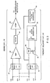
- an external defibrillator 10 constructed in accordance with this invention may include several subsystems as described below, it being understood that not all the subsystems are necessary for the system to operate.
- the defibrillator 10 is coupled to patient 11 by electrodes strategically placed on the patient's body to permit the defibrillator 10 to collect information from the patient regarding his current status and to deliver therapy.
- Fig. 1 shows symbolically two electrodes 12 and 14 being used to detect signals indicative of the cardiac condition of the patient and to deliver therapy, respectively, it being understood that more electrodes may be required to perform these functions, and that some electrodes may be used for both these functions.
- the signals acquired by electrode 12 are received by a sense circuit 18 which analyzes these signals and determines various cardiac parameters, such as the current cardiac rhythm. This information is fed to the controller 20.
- the controller a microprocessor, uses the parameters received from the sense circuit 18 together with other information to determine the current condition of the patient.
- the controller 20 provides the parameters to an arrhythmia detector 22.
- this detector is shown in Fig. 1 as a separate subsystem, but preferably it is implemented as software within the controller 20.
- the controller determines that therapy is required, it activates a therapy delivery circuit 24 which then delivers suitable shocks or other electrical signals through electrode 14.
- Information obtained from or about the patient, as well as data regarding therapy applied to the patient, is logged by a data logging circuit 28. Some of this information may be downloaded to a printer or shown on a display if so desired.
- Power to the defibrillator is provided by a power supply 30 which may include rechargeable or replaceable batteries.
- a self-test and diagnostic circuit 32 is used to monitor the other subsystems of the defibrillator as described below.
- the circuit 32 may monitor the power supply 30. If it determines that the power supply has a low energy backup capability, it may disable the therapy delivery circuit but allow continued monitoring of the patient. If the power supply level is very low, the circuit 32 may shut down the whole defibrillator.
- Circuit 32 may also monitor the coupling between the electrodes and the corresponding organ tissues. For example, circuit 32 may determine the impedance between the two electrodes. If this impedance is too high, the defibrillator may be inhibited from operating.
- Circuit 32 may also include a watchdog circuit (not shown) which is adapted to receive a signal from the controller 20 at predetermined intervals. In the absence of these signals, the watchdog circuit 32 determines that the controller 20 is inoperative and may shut down the defibrillator. The other elements and subsystems of the defibrillator 10 may be monitored by the circuit 32 in the same manner.
- a communication module 34 is used to establish communication with the outside world and to provide information to a remote device about the current operation and status of the defibrillator 10.
- the communication module 34 may include a cellular telephone capable of accessing an emergency number associated with a police station or an emergency room.
- the communication module 34 also includes a means of identifying the location of the defibrillator 10 to the remote device. This means may include a Global Positioning System (GPS) or other geographic locating systems.
- GPS Global Positioning System
- the defibrillator 10 operates in a completely automatic mode in which, once it is attached to the patient, does not require any intervention from the patient or an attendant. Therefore, the defibrillator can be used by virtually anyone, with no training required.
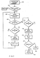
- this flow chart in the following scenario it is assumed that a patient has suffered a sudden cardiac arrest. A passerby notices that the patient is in distress and that an automatic defibrillator is nearby.
- the passerby attaches the electrodes of the defibrillator to the chest of the patient in accordance with instructions on the defibrillator, and he then activates a switch 36 indicating that the defibrillator 10 is properly in place.
- the activation of switch 36 awakens the controller 20 (step 202).
- step 204 the self-test/diagnostic circuit 32 ( Fig. 1 ) is activated.
- the circuit 32 checks the power reserves of power supply 30, the impedance between the electrodes 12 and 14, and any other critical portions of the system that may require attention. If during this self-check an abnormal condition is detected, an error indication is generated and the operation of the defibrillator 10 is halted. For example, if the impedance between the electrodes is too high, a message may be generated requesting that the electrodes be repositioned. Similarly, if the power supply voltage is determined to be too low, then a message may be generated indicating that new batteries are required. These messages may be shown in the display 38 ( Fig. 1 ). Additionally, or alternatively, an audio signal may be activated whenever the self-test indicates a problem with the system.
- the self test and diagnostic circuit 32 ( Fig. 1 ) may operate at regular intervals once the defibrillator is activated.
- step 206 the sense circuit 18 is activated to determine the current cardiac activity.
- physiological signals such as the ECG, blood pressure, pulse oximetry, and so on.
- the ECG is analyzed.
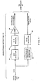
- two electrodes 12A and 12B are used to measure the ECG. These electrodes are attached across the chest of the patient in a well-known manner.
- the two electrodes 12A,12B are connected to a protection circuit 40.
- the purpose of the protection circuit 40 is to isolate the defibrillator 10 electrically from the patient and other sources of electrical signals.
- the signals from the electrodes 12A, 12B pass through the protection circuit 40 and then are amplified by an amplifier stage 42. After amplification, the signals pass through a filter stage 44 which eliminates noise from the signals. The filtered signals are next fed to a comparator stage 46 which insures that the signals fall within a predetermined range. The resulting signals are then sent to the controller 20 and arrhythmia detector 22.
- the arrhythmia detector 22 includes a QRS detector 60 adapted to detect a QRS complex. Since the defibrillator 10 has no information specific to the patient, the QRS detector must use generic criteria for detecting the QRS complexes, based, for example, on statistical information collected from other patients. Once a QRS complex is detected, a signal is sent to an R-R interval calculator 62 which uses the QRS complexes to calculate successive R-R intervals. The current R-R interval is provided to a comparator 64 which uses certain generic criteria to determine if the patient is suffering from ventricular tachycardia.
- a combination of heart rate and morphology analysis is used to detect ventricular tachycardia.
- a rhythm is classified as ventricular tachycardia when the heart rate is higher than ventricular tachycardia detection rate but lower than ventricular fibrillation detection rate and the morphological analysis indicate wide QRS complex.
- ventricular tachycardia Once ventricular tachycardia is detected, its rate is determined by rate detector 68 and this rate is provided to the controller 20.
- the detector 22 may also include a ventricular fibrillation detector 66 which analyzes the ECG signals from sense circuit 18 to detect ventricular fibrillation.
- Ventricular fibrillation is detected when the heart rate excesses the ventricular fibrillation rate or when the heart rate is irregular and the rhythm is proceeded by a shockable rhythm, which can be either ventricular tachycardia or ventricular fibrillation.
- R-R interval variability amplitude variability
- amplitude distribution analysis probability density function
- template matching on-set analysis
- signed or unsigned area under the curve waveform factor
- complexity analysis modular domain function
- frequency domain analysis frequency domain analysis
- Q-T interval analysis and S-T analysis.
- the sense circuit 18 detects intrinsic cardiac signals, as discussed above. In step 208 these signals are analyzed by the QRS detector. If a QRS complex is detected, in step 210 the R-R interval calculator and comparator 64 ( Fig. 4 ) determines whether life-threatening ventricular tachycardia (VT) is present. If in step 210 VT is not detected then it tests to see if the amplitude is less than a threshold, e.g. 0.2 millivolts. If the amplitude is less than the threshold, the rhythm is classified as fine ventricular fibrillation if it is proceeded by a shockable rhythm and the rhythm is classified as asystole if it is proceeded by a nonshockable rhythm.
- a threshold e.g. 0.2 millivolts.
- step 212 the controller 20 activates the communication module 30 to send a message to a service center, e.g. a police station and/or an emergency room that an emergency condition exists and that the defibrillator 10 is preparing to apply anti-tachycardia therapy.
- a service center e.g. a police station and/or an emergency room that an emergency condition exists and that the defibrillator 10 is preparing to apply anti-tachycardia therapy.
- Fig. 3 also shows, details of the therapy delivery circuit 24.
- the circuit 24 includes a low-voltage pulse generator 50 receiving commands from controller 20 and generating antitachycardia pacing pulses. These pulses are fed through a protection circuit 52 to a pair of output electrodes 14A, 14B.
- the protection circuit 52 is used to isolate the circuit 24 from the patient.
- Therapy circuit 24 further includes a high voltage shock generator 54, with or without a charge dump resistor 56 and an electronic switch 58.
- the generator 54 and switch 58 are responsive to commands from controller 20.
- the high voltage shock generator 54 receives a command from the controller 20 indicating that a shock may be required, the generator charges an internal capacitor (70) to a predetermined voltage.
- This capacitor 70 can be selectively discharged either to electrodes 14A, 14B or to a charge dissipating resistor 56 by switch 58 depending on the commands issued by controller 20.
- the controller 20 in step 214, the controller 20 generates a command to apply antitachycardia therapies, e.g. pacing pulses or cardioversion shocks.
- the generator 50 generates antitachycardia therapies to the electrodes 14A, 14B.
- these antitachycardia therapies are generated and applied synchronously with the detected QRS complexes. More particularly, each pacing pulse or cardioversion shock may be applied within a specified time, e.g. 60 milliseconds after a QRS complex (or R-wave) to insure that the therapy is not applied during a T-wave.
- This type of synchronized ventricular tachycardia therapy is important because it has been found that a therapy delivered on a T-wave can induce ventricular fibrillation, a condition worse than ventricular tachycardia.
- a manual synchronizing button was provided in some prior-art external defibrillators.
- the present defibrillator is superior to these prior art defibrillators because it synchronizes automatically antitachycardia therapy, either pacing or cardioversion, to-the R-waves, thereby advantageously reducing the chances of inducing ventricular fibrillation.
- This mode is further advantageous because it reduces the delay in applying therapy to the patient and it eliminates possible operator error.
- step 208 If in step 208 a QRS complex is not detected, then in step 214 the ventricular fibrillation detector 66 ( Fig. 4 ) and rate detector 68 are used to detect a life threatening ventricular fibrillation. In the presence of this condition, in step 218 a message is sent indicating that defibrillation shock therapy is required.
- step 220 the controller 20 ( Fig. 1 ) sends a command to the high-voltage shock generator 54 ( Fig. 3 ) to set the HV generator and to cause it to charge its capacitor 70.
- step 222 a reconfirmation step is provided.
- a final decision is made as to whether a high-level defibrillation shock is required.
- One criteria for this determination may be to check the output of rate detector 68 ( Fig. 4 ) to determine if a life threatening ventricular fibrillation is still present.
- Another criterion could be to check whether switch 36 ( Fig. 1 ) has been activated.
- This switch 36 now may be activated, for example, by the patient, if conscious, or by the attendant in the case that the defibrillation shock is not required. If in step 222 it is determined that a fibrillation shock is not necessary, then in step 224 the energy of internal capacitor 70 is dumped by switch 58 through resistor 56 ( Fig. 3 ). Otherwise, in step 226 a shock is applied through the protective network 52 ( Fig. 3 ) and electrodes 14A, 14B, to the patient.
- a cardioversion or defibrillation shock can be either mono-phasic or multi-phasic. Again, the parameters for the cardioversion and defibrillation shocks can be generic or can be patient specific. Preferably each therapy is delivered synchronously with the cardiac fibrillations if possible.
- the detection circuit can-have only one indicative signal for all life threatening arrhythmias, which include ventricular tachycardia and ventricular fibrillation.
- a therapy is delivered to the patient as either synchronized cardioversion to an R wave or asynchronized defibrillation if no R waves are found.
- FIGS 1 , 3 and 4 separate electrodes 12, 14 or corresponding electrode pairs 12A, 12B and 14A, 14B of the sensing circuit 18 or therapy delivery circuit 24 are shown as being used to acquire signals from the heart and to deliver therapy. However, a single pair or set of electrodes may be used to perform both functions.
- the controller 20 Once the controller 20 becomes active and the defibrillator10 has passed the self-test step 204, its operation is automatically logged in the data log memory 28.
- the logging includes details of the QRS complexes sensed, the ventricular tachycardia or fibrillation rates, and a history of the therapy applied to a patient. This information may be selectively uploaded from data log memory 28 to a separate location.
- the defibrillator 10 may be provided with the display 38 which may be used to provide instructions for the operation of the defibrillator 10 or to display the data logged in memory 28.
- the memory 28 may include a hard disk, an optical disk, a solid state memory, a flash card, a CD recorder or a combination of any of these devices.
- an external defibrillator is described herein which can provide automatic therapy to patients with life threatening arrhythmias or sudden cardiac arrest. Any person can attach the device to the patient since no special training is required. Once the defibrillator is properly attached to the patient, the condition of the patient is continuously and automatically monitored. The defibrillator analyzes physiological signals of the patient to automatically detect an arrhythmia and deliver therapy to the patient if necessary, using generic criteria.
- An important feature of the invention is that it is based on a programmable controller whose programming parameters are not customized for each patient, but instead contain generic parameters which allow the defibrillator to operate effectively for any patient. Consequently, the defibrillator can be effective without reprogramming between patients.
- main operation mode is fully automatic, different operation modes, such as advisory or manual, can be included to provide a trained operator the control to the device.
- the defibrillator performs a self-test to insure that all its components/subassemblies and the connections to the patient are operational.
- a visual indication and/or an audio signal can indicate that the defibrillator is not operational.
- the defibrillator may be provided with a display for showing instructions, error messages, data descriptive' of the patient's current/past condition, and the therapy applied by the defibrillator.
- a communication module may be also be provided within the defibrillator to alert personnel at a remote location that the patient has experienced a life threatening episode and that therapy is being delivered by the automatic defibrillator. Emergency personnel (such as an ambulance) may be dispatched to provide assistance. Data from the data logging memory may also be transmitted at the same time.
- the communication module may include a locator unit such as a GPS (Global Positioning System) which can provide the physical location of the patient.
- the communication module may make use of a cellular telephone system, wireless radio or telephone system, a controller network, the Internet, and so on.
- the communication module may also be activated by the self-test and diagnostic circuit if tests show that the defibrillator needs servicing or repair.
- the sensing of physiological signals and therapy can be affected on different electrodes dedicated for each of these functions or can be affected on a single set of electrodes.
- an external defibrillator that can be used to apply therapy to any patient, comprises:
- said cardiac arrhythmia detector includes a comparator adapted to compare said physiological signal to a threshold value, said threshold value being generic to cardiac patients.
- said sense circuit includes a signal detector adapted to detect a specific cardiac signal based on generic criteria.
- said detector circuit is adapted to generate one shockable rhythm signal indicative of life threatening rhythms, for examples, a ventricular tachycardia and a ventricular fibrillation.
- a publicly accessible external defibrillator for automatically generating a generating a generic cardiac therapy of a person suffering from a life threatening cardiac condition, comprises:
- the external defibrillator further comprises a self-test and diagnostic circuit adapted to run tests on said external defibrillator to determine if said external defibrillator is operational.
Landscapes
- Health & Medical Sciences (AREA)
- Cardiology (AREA)
- Heart & Thoracic Surgery (AREA)
- Engineering & Computer Science (AREA)
- Biomedical Technology (AREA)
- Nuclear Medicine, Radiotherapy & Molecular Imaging (AREA)
- Radiology & Medical Imaging (AREA)
- Life Sciences & Earth Sciences (AREA)
- Animal Behavior & Ethology (AREA)
- General Health & Medical Sciences (AREA)
- Public Health (AREA)
- Veterinary Medicine (AREA)
- Electrotherapy Devices (AREA)
Applications Claiming Priority (2)
| Application Number | Priority Date | Filing Date | Title |
|---|---|---|---|
| US09/591,669 US6658290B1 (en) | 2000-06-12 | 2000-06-12 | Public access defibrillator |
| EP01906537A EP1289603B1 (de) | 2000-06-12 | 2001-01-10 | Öffentlicher defibrillator |
Related Parent Applications (2)
| Application Number | Title | Priority Date | Filing Date |
|---|---|---|---|
| EP01906537.4 Division | 2001-01-10 | ||
| EP01906537A Division EP1289603B1 (de) | 2000-06-12 | 2001-01-10 | Öffentlicher defibrillator |
Publications (2)
| Publication Number | Publication Date |
|---|---|
| EP2116276A2 true EP2116276A2 (de) | 2009-11-11 |
| EP2116276A3 EP2116276A3 (de) | 2010-12-01 |
Family
ID=24367390
Family Applications (2)
| Application Number | Title | Priority Date | Filing Date |
|---|---|---|---|
| EP01906537A Expired - Lifetime EP1289603B1 (de) | 2000-06-12 | 2001-01-10 | Öffentlicher defibrillator |
| EP09168921A Withdrawn EP2116276A3 (de) | 2000-06-12 | 2001-01-10 | Öffentlich zugänglicher Defibrillator |
Family Applications Before (1)
| Application Number | Title | Priority Date | Filing Date |
|---|---|---|---|
| EP01906537A Expired - Lifetime EP1289603B1 (de) | 2000-06-12 | 2001-01-10 | Öffentlicher defibrillator |
Country Status (5)
| Country | Link |
|---|---|
| US (2) | US6658290B1 (de) |
| EP (2) | EP1289603B1 (de) |
| AU (1) | AU2001234436A1 (de) |
| DE (1) | DE60140119D1 (de) |
| WO (1) | WO2001095977A1 (de) |
Families Citing this family (63)
| Publication number | Priority date | Publication date | Assignee | Title |
|---|---|---|---|---|
| US20040031045A1 (en) * | 1997-11-20 | 2004-02-12 | Ivanyi Thomas P. | System and method for measuring and storing information pertaining to television viewer or user behavior |
| JP2003521355A (ja) | 2000-02-04 | 2003-07-15 | ゼットエムデー コーポレイション | 統合された救急蘇生法 |
| US7920917B2 (en) * | 2003-07-17 | 2011-04-05 | Physio-Control, Inc. | External defibrillator and methods for operating the external defibrillator |
| US7087075B2 (en) | 2002-09-30 | 2006-08-08 | Medtronic Emergency Response Systems, Inc. | Feedback system for rapid induction of mild hypothermia |
| US7179279B2 (en) | 2002-09-30 | 2007-02-20 | Medtronic Physio Control Corp. | Rapid induction of mild hypothermia |
| US6827695B2 (en) | 2002-10-25 | 2004-12-07 | Revivant Corporation | Method of determining depth of compressions during cardio-pulmonary resuscitation |
| US7289029B2 (en) | 2002-12-31 | 2007-10-30 | Medtronic Physio-Control Corp. | Communication between emergency medical device and safety agency |
| US6961612B2 (en) * | 2003-02-19 | 2005-11-01 | Zoll Medical Corporation | CPR sensitive ECG analysis in an automatic external defibrillator |
| US20040172069A1 (en) * | 2003-02-28 | 2004-09-02 | Hakala Douglas T. | Recording information for emergency call by defibrillator apparatus |
| US7805190B2 (en) | 2003-04-02 | 2010-09-28 | Physio-Control, Inc. | Defibrillators customized for anticipated patients |
| FR2855059B1 (fr) * | 2003-05-22 | 2006-03-17 | Schiller Medical | Defibrillateur externe a deux modes de fonctionnement. |
| US7220235B2 (en) * | 2003-06-27 | 2007-05-22 | Zoll Medical Corporation | Method and apparatus for enhancement of chest compressions during CPR |
| US7623915B2 (en) | 2003-07-16 | 2009-11-24 | Medtronic Physio-Control Corp. | Interactive first aid information system |
| JP2012091021A (ja) | 2003-11-06 | 2012-05-17 | Zoll Medical Corp | 胸部圧迫適用中の生理学的信号を解析する装置 |
| US20050101889A1 (en) * | 2003-11-06 | 2005-05-12 | Freeman Gary A. | Using chest velocity to process physiological signals to remove chest compression artifacts |
| US7706878B2 (en) * | 2004-05-07 | 2010-04-27 | Zoll Medical Corporation | Automated caregiving device with prompting based on caregiver progress |
| US7565194B2 (en) | 2004-05-12 | 2009-07-21 | Zoll Medical Corporation | ECG rhythm advisory method |
| WO2005112749A1 (en) | 2004-05-12 | 2005-12-01 | Zoll Medical Corporation | Ecg rhythm advisory method |
| US20060094949A1 (en) * | 2004-10-29 | 2006-05-04 | Coonce Charles K | Methods and systems for real time response to medical emergencies |
| US20060095950A1 (en) * | 2004-10-29 | 2006-05-04 | Coonce Charles K | Methods and multi-screen systems for real time response to medical emergencies |
| US7904152B2 (en) * | 2004-12-09 | 2011-03-08 | Physio-Control, Inc. | External defibrillator with charge advisory algorithm |
| WO2006102420A2 (en) * | 2005-03-21 | 2006-09-28 | Defibtech, Llc | Pcb blade connector system and method |
| WO2006102425A2 (en) | 2005-03-21 | 2006-09-28 | Defibtech, Llc | Environmentally responsive active status indicator system and method |
| EP1866025A2 (de) * | 2005-03-21 | 2007-12-19 | Defibtech, LLC | System und verfahren zur darstellung von informationen zum defibrillatorstatus im standby-modus |
| US20060215024A1 (en) * | 2005-03-23 | 2006-09-28 | Coonce Charles K | Method and real time emergency response surveillances system with an emergency switch |
| EP1919558A4 (de) * | 2005-08-04 | 2009-06-03 | Access Cardiosystems Inc | Automatischer externer defibrillator (aed) mit drahtloser kommunikation |
| US8116863B2 (en) * | 2006-03-21 | 2012-02-14 | Defibtech, Llc | System and method for effectively indicating element failure or a preventive maintenance condition in an automatic external defibrillator (AED) |
| US8099163B2 (en) * | 2006-04-04 | 2012-01-17 | The Invention Science Fund I, Llc | Automated defibrillator |
| US8086320B2 (en) * | 2006-05-22 | 2011-12-27 | Saketkhou B Benjamin | Wireless communication device with integrated defibrillator |
| US20070270909A1 (en) * | 2006-05-22 | 2007-11-22 | Saketkhou B Benjamin | Wireless communication device with integrated defibrillator |
| US7881785B2 (en) | 2008-03-26 | 2011-02-01 | Cardiac Science Corporation | Method and apparatus for defrosting a defibrillation electrode |
| US20220020490A1 (en) | 2009-07-21 | 2022-01-20 | Zoll Medical Corporation | Systems and methods for ems device communications interface |
| US20110172550A1 (en) * | 2009-07-21 | 2011-07-14 | Michael Scott Martin | Uspa: systems and methods for ems device communication interface |
| WO2011127459A1 (en) | 2010-04-09 | 2011-10-13 | Zoll Medical Corporation | Systems and methods for ems device communications interface |
| US9498152B2 (en) | 2009-10-23 | 2016-11-22 | Scion Medical Limited | Method and system for expediting the rescue of victims experiencing sudden cardiac arrest (SCA) when used in conjunction with an automated external defibrillator (AED) |
| US8509881B2 (en) | 2009-11-03 | 2013-08-13 | Cardiac Science Corporation | True ECG measurement during cardio pulmonary resuscitation by adaptive piecewise stitching algorithm |
| WO2012154870A2 (en) | 2011-05-09 | 2012-11-15 | Zoll Medical Corporation | Systems and methods for ems navigation user interface |
| US20130012151A1 (en) * | 2011-07-05 | 2013-01-10 | Hankins Mark S | Defibrillator with integrated telecommunications |
| US8942800B2 (en) | 2012-04-20 | 2015-01-27 | Cardiac Science Corporation | Corrective prompting system for appropriate chest compressions |
| US20130282068A1 (en) * | 2012-04-20 | 2013-10-24 | Mustafa H. Sagiroglu | Aed treatment recommendation method and device |
| US9126055B2 (en) | 2012-04-20 | 2015-09-08 | Cardiac Science Corporation | AED faster time to shock method and device |
| US8930040B2 (en) | 2012-06-07 | 2015-01-06 | Zoll Medical Corporation | Systems and methods for video capture, user feedback, reporting, adaptive parameters, and remote data access in vehicle safety monitoring |
| US10127810B2 (en) | 2012-06-07 | 2018-11-13 | Zoll Medical Corporation | Vehicle safety and driver condition monitoring, and geographic information based road safety systems |
| EP2967394A4 (de) | 2013-03-15 | 2016-11-09 | Zoll Medical Corp | Ekg-rauschminderungssystem zur entfernung von vehikelbewegungsartefakten |
| WO2014149981A1 (en) | 2013-03-15 | 2014-09-25 | Zoll Medical Corporation | Processing impedance signals for breath detection |
| CN105324773A (zh) | 2013-05-10 | 2016-02-10 | 卓尔医学产品公司 | 与ems临床和操作绩效相关的计分、评价和反馈 |
| EP3524315B1 (de) | 2014-02-24 | 2020-08-26 | Element Science, Inc. | Externer defibrillator |
| US10596064B2 (en) | 2014-03-18 | 2020-03-24 | Zoll Medical Corporation | CPR chest compression system with tonometric input and feedback |
| EP3673953B1 (de) | 2015-03-27 | 2022-09-14 | Zoll Medical Corporation | System zur erfassung und verfolgung von ekg- und defibrillatorelektroden |
| US9734720B2 (en) | 2015-04-01 | 2017-08-15 | Zoll Medical Corporation | Response mode verification in vehicle dispatch |
| ES2946910T3 (es) | 2015-08-26 | 2023-07-27 | Element Science Inc | Dispositivos de desfibrilación portátiles |
| EP4523613A3 (de) | 2015-10-16 | 2025-05-07 | Zoll Medical Corporation | Doppelsensorelektroden zur bereitstellung von verstärkter wiederbelebungsrückkopplung |
| US10561575B2 (en) | 2016-03-31 | 2020-02-18 | Zoll Medical Corporation | Monitoring CPR by a wearable medical device |
| US11097121B2 (en) | 2017-10-02 | 2021-08-24 | Avive Solutions, Inc. | Modular defibrillator architecture |
| US11640755B2 (en) | 2018-09-14 | 2023-05-02 | Avive Solutions, Inc. | Real time defibrillator incident data |
| US12430998B2 (en) | 2018-09-14 | 2025-09-30 | Avive Solutions, Inc. | Device based responder network activation and virtual assistant integration |
| WO2020056028A1 (en) | 2018-09-14 | 2020-03-19 | Avive Solutions, Inc. | Shockable heart rhythm classifier for defibrillators |
| US11645899B2 (en) | 2018-09-14 | 2023-05-09 | Avive Solutions, Inc. | Responder network |
| US12106650B2 (en) | 2018-09-14 | 2024-10-01 | Avive Solutions, Inc. | PSAP/public responder network integrations |
| US11253715B2 (en) | 2018-10-10 | 2022-02-22 | Element Science, Inc. | Wearable medical device with disposable and reusable components |
| US11869338B1 (en) | 2020-10-19 | 2024-01-09 | Avive Solutions, Inc. | User preferences in responder network responder selection |
| EP4221826A4 (de) | 2020-09-30 | 2024-10-30 | Zoll Medical Corporation | Fernüberwachungsvorrichtungen und zugehörige verfahren und systeme mit hören eines hörbaren aed-signals |
| MX2023008751A (es) | 2021-01-28 | 2023-09-15 | Usa Medical Electronix Inc | Desfibrilador externo automatizado de bolsillo. |
Citations (1)
| Publication number | Priority date | Publication date | Assignee | Title |
|---|---|---|---|---|
| US5474574A (en) | 1992-06-24 | 1995-12-12 | Cardiac Science, Inc. | Automatic external cardioverter/defibrillator |
Family Cites Families (18)
| Publication number | Priority date | Publication date | Assignee | Title |
|---|---|---|---|---|
| US3703900A (en) | 1969-12-02 | 1972-11-28 | Cardiac Resuscitator Corp | Cardiac resuscitator |
| US5078134A (en) * | 1988-04-25 | 1992-01-07 | Lifecor, Inc. | Portable device for sensing cardiac function and automatically delivering electrical therapy |
| US5391187A (en) * | 1994-02-22 | 1995-02-21 | Zmd Corporation | Semiautomatic defibrillator with heart rate alarm driven by shock advisory algorithm |
| US5507778A (en) * | 1994-02-22 | 1996-04-16 | Zmd Corporation | Semiautomatic defibrillator with synchronized shock delivery |
| US5496349A (en) * | 1994-03-11 | 1996-03-05 | Physio-Control Corporation | Method and system for automatic or semi-automatic defilbrillation using redundant processing |
| US5735876A (en) * | 1994-05-31 | 1998-04-07 | Galvani Ltd. | Electrical cardiac output forcing method and apparatus for an atrial defibrillator |
| US5645571B1 (en) * | 1995-08-01 | 1999-08-24 | Surviva Link Corp | Automated external defibrillator with lid activated self-test system |
| DE69631722T2 (de) * | 1995-08-08 | 2005-04-07 | Cardiac Science, Inc., Minneapolis | Automatisierte externe Defibrillation mit Selbst-Test-System |
| US6134468A (en) | 1996-12-31 | 2000-10-17 | Agilent Technologies, Inc. | Method and apparatus for reducing defibrillation energy |
| US6148233A (en) | 1997-03-07 | 2000-11-14 | Cardiac Science, Inc. | Defibrillation system having segmented electrodes |
| US5899925A (en) * | 1997-08-07 | 1999-05-04 | Heartstream, Inc. | Method and apparatus for aperiodic self-testing of a defibrillator |
| CA2732191C (en) * | 1997-08-27 | 2015-04-14 | Zoll Circulation, Inc. | Resuscitation device |
| US5944669A (en) * | 1997-11-20 | 1999-08-31 | Lifecor, Inc. | Apparatus and method for sensing cardiac function |
| US6246906B1 (en) * | 1998-03-19 | 2001-06-12 | Cardiac Pacemakers, Inc. | System and method for treating atrial arrhythmias |
| US6141584A (en) * | 1998-09-30 | 2000-10-31 | Agilent Technologies, Inc. | Defibrillator with wireless communications |
| US6246907B1 (en) * | 1999-12-01 | 2001-06-12 | Cardiacscience, Inc. | Automatic external cardioverter/defibrillator with cardiac rate detector and method of operating the same |
| US6289243B1 (en) * | 1999-12-01 | 2001-09-11 | Cardiac Science, Inc. | Automatic external cardioverter/defibrillator with tachyarrhythmia detector using a modulation (amplitude and frequency) domain function |
| US6405082B1 (en) * | 2000-01-24 | 2002-06-11 | Koninklijke Philips Electronics N.V. | Method and apparatus for distinguishing between therapy modes in a defibrillator |
-
2000
- 2000-06-12 US US09/591,669 patent/US6658290B1/en not_active Expired - Lifetime
-
2001
- 2001-01-10 AU AU2001234436A patent/AU2001234436A1/en not_active Abandoned
- 2001-01-10 WO PCT/US2001/000802 patent/WO2001095977A1/en not_active Ceased
- 2001-01-10 DE DE60140119T patent/DE60140119D1/de not_active Expired - Lifetime
- 2001-01-10 EP EP01906537A patent/EP1289603B1/de not_active Expired - Lifetime
- 2001-01-10 EP EP09168921A patent/EP2116276A3/de not_active Withdrawn
-
2003
- 2003-10-16 US US10/688,362 patent/US6993386B2/en not_active Expired - Lifetime
Patent Citations (1)
| Publication number | Priority date | Publication date | Assignee | Title |
|---|---|---|---|---|
| US5474574A (en) | 1992-06-24 | 1995-12-12 | Cardiac Science, Inc. | Automatic external cardioverter/defibrillator |
Also Published As
| Publication number | Publication date |
|---|---|
| EP2116276A3 (de) | 2010-12-01 |
| US6658290B1 (en) | 2003-12-02 |
| EP1289603B1 (de) | 2009-10-07 |
| EP1289603A1 (de) | 2003-03-12 |
| DE60140119D1 (de) | 2009-11-19 |
| WO2001095977A1 (en) | 2001-12-20 |
| US20040082972A1 (en) | 2004-04-29 |
| EP1289603A4 (de) | 2004-12-15 |
| US6993386B2 (en) | 2006-01-31 |
| AU2001234436A1 (en) | 2001-12-24 |
Similar Documents
| Publication | Publication Date | Title |
|---|---|---|
| US6658290B1 (en) | Public access defibrillator | |
| US6289243B1 (en) | Automatic external cardioverter/defibrillator with tachyarrhythmia detector using a modulation (amplitude and frequency) domain function | |
| US6246907B1 (en) | Automatic external cardioverter/defibrillator with cardiac rate detector and method of operating the same | |
| US6269267B1 (en) | Configurable arrhythmia analysis algorithm with security interface | |
| US6671547B2 (en) | Adaptive analysis method for an electrotherapy device and apparatus | |
| US5474574A (en) | Automatic external cardioverter/defibrillator | |
| US11213691B2 (en) | Ambulatory medical device interaction | |
| US20020103508A1 (en) | Remotely operated defibrillator | |
| US6125298A (en) | Defibrillation system for pediatric patients | |
| US7496409B2 (en) | Implantable medical device system and method with signal quality monitoring and response | |
| US11160991B2 (en) | Medical device with lack-of-readiness alarm | |
| US6405082B1 (en) | Method and apparatus for distinguishing between therapy modes in a defibrillator | |
| US20030187479A1 (en) | Method and apparatus for preventing heart tachyarrhythmia | |
| WO2006083785A1 (en) | Communication between an external defibrillator and an implantable medical device | |
| US6115627A (en) | Intracardiac predictor of imminent arrhythmia | |
| US20240041381A1 (en) | Arrhythmia detection in a wearable medical system | |
| US20070213774A1 (en) | Defibrillation threshold testing system with automated control of external defibrillator | |
| US12508436B2 (en) | Ambulatory medical device interaction | |
| JPH05269213A (ja) | 心室細動および心停止検出機能付除細動器 |
Legal Events
| Date | Code | Title | Description |
|---|---|---|---|
| PUAI | Public reference made under article 153(3) epc to a published international application that has entered the european phase |
Free format text: ORIGINAL CODE: 0009012 |
|
| AC | Divisional application: reference to earlier application |
Ref document number: 1289603 Country of ref document: EP Kind code of ref document: P |
|
| AK | Designated contracting states |
Kind code of ref document: A2 Designated state(s): DE FR GB IT |
|
| PUAL | Search report despatched |
Free format text: ORIGINAL CODE: 0009013 |
|
| AK | Designated contracting states |
Kind code of ref document: A3 Designated state(s): DE FR GB IT |
|
| 17P | Request for examination filed |
Effective date: 20110531 |
|
| 17Q | First examination report despatched |
Effective date: 20111129 |
|
| STAA | Information on the status of an ep patent application or granted ep patent |
Free format text: STATUS: THE APPLICATION IS DEEMED TO BE WITHDRAWN |
|
| 18D | Application deemed to be withdrawn |
Effective date: 20130817 |