EP2115237B1 - Fixation for a headrail of a shading device - Google Patents
Fixation for a headrail of a shading device Download PDFInfo
- Publication number
- EP2115237B1 EP2115237B1 EP08731512.3A EP08731512A EP2115237B1 EP 2115237 B1 EP2115237 B1 EP 2115237B1 EP 08731512 A EP08731512 A EP 08731512A EP 2115237 B1 EP2115237 B1 EP 2115237B1
- Authority
- EP
- European Patent Office
- Prior art keywords
- headrail
- lock bar
- bracket
- lock lever
- wall
- Prior art date
- Legal status (The legal status is an assumption and is not a legal conclusion. Google has not performed a legal analysis and makes no representation as to the accuracy of the status listed.)
- Not-in-force
Links
- 230000006835 compression Effects 0.000 claims description 6
- 238000007906 compression Methods 0.000 claims description 6
- 230000007935 neutral effect Effects 0.000 claims description 4
- 230000000994 depressogenic effect Effects 0.000 description 6
- 239000000463 material Substances 0.000 description 5
- 125000006850 spacer group Chemical group 0.000 description 3
- 239000011324 bead Substances 0.000 description 2
- 230000000295 complement effect Effects 0.000 description 2
- 238000004140 cleaning Methods 0.000 description 1
- 230000000881 depressing effect Effects 0.000 description 1
- 230000000717 retained effect Effects 0.000 description 1
Images







Classifications
-
- E—FIXED CONSTRUCTIONS
- E06—DOORS, WINDOWS, SHUTTERS, OR ROLLER BLINDS IN GENERAL; LADDERS
- E06B—FIXED OR MOVABLE CLOSURES FOR OPENINGS IN BUILDINGS, VEHICLES, FENCES OR LIKE ENCLOSURES IN GENERAL, e.g. DOORS, WINDOWS, BLINDS, GATES
- E06B9/00—Screening or protective devices for wall or similar openings, with or without operating or securing mechanisms; Closures of similar construction
- E06B9/24—Screens or other constructions affording protection against light, especially against sunshine; Similar screens for privacy or appearance; Slat blinds
- E06B9/26—Lamellar or like blinds, e.g. venetian blinds
- E06B9/28—Lamellar or like blinds, e.g. venetian blinds with horizontal lamellae, e.g. non-liftable
- E06B9/30—Lamellar or like blinds, e.g. venetian blinds with horizontal lamellae, e.g. non-liftable liftable
- E06B9/32—Operating, guiding, or securing devices therefor
- E06B9/323—Structure or support of upper box
Definitions
- the present invention relates generally to systems for mounting a headrail for a covering for an architectural opening and more specifically to a mounting bracket having a lever lock for securing the headrail to the mounting bracket.
- Coverings for architectural openings typically include a retractable panel of material supported by a headrail.
- the coverings are typically movable between extended positions wherein the panel of material extends across the architectural opening and a retracted position where the panel of material is either wrapped or gathered within or immediately adjacent to the headrail.
- the headrail further includes control systems for moving the covering between extended and retracted positions and in the case of *Venetian blinds for tilting the slats of the blind between open and closed positions.
- Headrails are provided in various forms and configurations dictated partly by aesthetics and partly by function. In any circumstance, mounting brackets are provided that can be secured to a frame around the architectural opening and utilized to support the headrail.
- the mounting brackets have some form of a release mechanism so that the headrail is releasably secured to the mounting bracket whereby when in use it is reliably secure to prevent an inadvertent removal but can be released and removed for cleaning purposes or the like.
- US patent application no. US 2007/0000621 discloses a mounting bracket for a covering for architectural openings such as windows, doors, archways, and the like and includes complementary components on the headrail and the mounting bracket to permit the mounting bracket to be inserted into the headrail.
- a lock lever is provided with access forwardly of the headrail to lock the headrail in position on the mounting bracket or condition the mounting bracket for release of the headrail from a temporarily secured relationship.
- the present invention embodies a system for releasably mounting a headrail for a covering for an architectural opening to mounting brackets in a reliable, efficient, and easy to operate manner.
- the headrail and mounting brackets are complementary in that the headrail can be temporarily snapped onto the mounting brackets and then firmly locked in a mounted position with a readily accessible lever arm.
- the mounting bracket has a depressible catch arm that is automatically depressed by a ledge on the headrail as the headrail is advanced to a predetermined position relative to the mounting bracket at which point the catch arm snaps into a temporarily secured position.
- a lever arm on the bracket can then be manually pivoted to a lock position to activate a slide-lock bar that prevents the catch arm from again being depressed thereby securely locking the headrail to the mounting bracket to prevent an inadvertent removal of the headrail.
- the lever arm of course can be moved to a release position to permit depression of the catch arm by applying reasonable manual force to the headrail.
- a pair of mounting brackets 30 in accordance with the present invention are seen with a headrail 32 for a covering for an architectural opening (not shown). While the frame for the architectural opening to which the brackets 30 can be mounted is not illustrated, the connection will be fully appreciated with the description of a bracket hereafter.
- the headrail 32 can be seen to have a generally flat front wall 34 with an arcuate lower edge 36 and a relatively flat top wall 38 projecting rearwardly from the top edge of the front wall.
- the top wall has a depressed ledge 40 along its rearwardmost edge defining a bevel surface 42 and a rib spacer 44 projecting downwardly at an intermediate location between the front wall 34 and the ledge 40.
- the headrail is typically extruded so that all of its features extend the full length of the headrail.
- a support arm 46 extends rearwardly from the front wall of the headrail with the support arm having a lip 48 along its rearwardmost edge.
- the lip 48, ledge 40, and rib spacer 44 all cooperate in defining a pocket 50 in which a portion of the mounting bracket can be inserted.
- the headrail 32 is shown connected to a mounting bracket 30 of the present invention with Fig. 4 showing the mounting bracket in a release position and Fig. 3 in a locking position.
- a roller 52 which might be found in a headrail of a roll-up shade is illustrated positioned within the headrail and beneath the mounting bracket for illustrative purposes only.
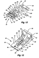
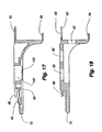
- the mounting bracket is probably best seen in Figs. 12-18 .
- the bracket is made of a somewhat rigid plastic material having some flexibility depending upon the thickness of the plastic for purposes which will become apparent with the description hereafter.
- the bracket 30 can be seen to have a horizontal base 54, a downturned back wall 56 off the rear edge of the base, and upper 58 and lower 60 horizontal flanges extending rearwardly from the back wall.
- the upper flange, the back wall, and the base all have openings 62 therethrough as possibly best seen in Figs. 12, 13 , 14 , and 18 through which fasteners (not shown) can extend to secure the bracket to the frame around an architectural opening.
- the openings 62 are provided in both vertical and horizontal surfaces of the bracket so the bracket can be mounted to a vertical or horizontal surface of the frame depending upon the type of mounting desired for the covering.
- the base 54 has a relatively thick rear portion 64 with a flat upper surface 66 and a slide plate 68 projecting forwardly from the rear portion along a lower edge thereof.
- the slide plate has a pair of support arms 70 along opposite sides and an integral lead bar 72 connecting the support arms along the forwardmost edge of the slide plate so as to define a rectangular opening 74 therebetween.
- the opening has a spring catch arm 76 positioned therein with the catch arm having a relatively thin portion 78 integrally connected with and extending forwardly from the relatively thick rear portion 64 of the base in a living hinge and a bevel head 80 at the forwardmost end of the thin portion.
- the bevel head has front 82 and rear 84 upwardly directed bevel surfaces for purposes to be described hereafter.
- the thin portion 78 is adapted to flex slightly at the living hinge so that the bevel head 80 can be depressed within the rectangular opening 74 in the slide plate 68.
- the thin portion of the catch arm itself has a rectangular slot 86 formed therein for a purpose to be described hereafter.
- a pair of overhanging lips 88 project forwardly from the relatively thick rear portion 64 of the base in spaced overlying relationship with a rear portion of the slide plate 68.
- the overhanging lips define a space therebetween that is continuous with a shallow groove 90 formed in the flat upper surface 66 of the rear portion 64 of the base.
- a vertical hole 92 is provided in the shallow groove for receipt of a removable pivot pin 94 having an enlarged head as seen in Figs. 7 and 9-11 .
- the pivot pin pivotally secures a lock lever 96 to the base as will be described later.
- the rectangular opening 74 in the slide plate 68 in which the spring catch arm 76 is positioned is continuous with a relatively narrow recessed channel 98 in the bottom of the relatively thick rear portion 64 of the base, which in turn is continuous with a slot-like opening 100 through the rear portion.
- a pair of support shoulders 102 extend along the sides of the slot-like opening 100 in the base along the bottom thereof.
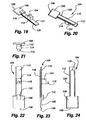
- a slide-lock bar 104 shown in detail in Figs. 8 and 19-24 is slidably positioned within the opening 74 in the slide plate, the continuous recessed channel 98 and slot-like opening 100 in the rear portion of the base.
- the slide-lock bar slidably underlies the spring catch arm 76.
- the slide-lock bar can be seen to have a flat paddle head 106 with a beveled leading edge 108, a guide block 110 extending upwardly from a rear portion of the paddle head and a slide arm 112 extending rearwardly from the paddle head.
- the slide arm has a raised block 114 at approximately its longitudinal center with the raised block having a cylindrical guide pin 116 projecting upwardly.
- the underside of the slide arm has an elongated centered tongue 118 formed integrally thereon ( Fig. 20 ) which projects downwardly a small amount from the remainder of the slide arm.
- the tongue is also relatively narrow so as to define support edges 120 along opposite sides of the slide arm which are adapted to ride upon the support shoulders 102.
- the slide-lock bar 104 is positioned in the base 54 so that the support edges 120 on the underside of the slide-lock bar are supported on the support shoulders 102 for sliding movement and the paddle head 106 is disposed within the rectangular opening 74 in the slide plate 68 immediately beneath the spring catch arm 76.
- the guide block 110 on the paddle head projects into the rectangular slot 86 formed in the spring catch arm to assist in guiding sliding movement of the slide-lock bar.
- the slide-lock bar is also made of a relatively thin plastic so it too has some flexibility along its length. It should be noted that when the spring catch arm is depressed downwardly, it engages the top surface of the paddle head of the slide-lock bar also depressing the paddle head downwardly due to their uniform flexibility.
- the lock lever 122 which is used to engage and disengage the locking mechanism in the bracket, is seen in detail in Figs. 25-28 . It can there be seen to have an elongated relatively flat body 124 with a diagonal gripping rib 126 at one end, a semicircular opposite end 128, a circular passage 130 extending vertically through the body at a location relatively close to the opposite end and an arcuate push-pull slot 132 extending vertically through the flat body between the circular opening and the opposite end of the flat body from the gripping rib.
- the push-pull slot while being arcuate extends at approximately a 45 degree angle relative to the length of the lever arm for a purpose to be described hereafter.
- the lock lever 122 is secured to the base 54 by positioning the gripping rib 126 at a location beyond the slide plate 68 of the base with the opposite end 128 of the lock lever being positioned within the shallow groove 90 provided in the top surface of the base.
- the circular passage 130 through the lock lever is aligned with the hole 92 in the shallow groove in the base and the pivot pin 94 is inserted into the hole to pivotally connect the lock lever to the base.
- the width of the lock lever body 124 is less than the width of the shallow groove so the lock lever is free to pivot within limits about the pivot pin.
- a notch 134 is provided in a side of the flat body 124 to accommodate the adjacent overhanging lip 88 when the lock lever is in the locking position of Fig. 3 .
- the guide pin 116 on the slide-lock bar 104 extends into the push-pull slot 132 of the lock lever.
- the push-pull slot forces the guide pin to move linearly along the length of the bracket so that the slide-lock bar can be moved reciprocally forwardly and rearwardly along the length of the bracket with pivotal movement of the lock lever.
- the lock lever has arcuately spaced detents 136 in its opposite end 128 that releasably receives vertical beads 138 formed in the adjacent arcuate wall 140 of the shallow groove 90. The detents and beads assist in retaining the lock lever in either a locking or release position to be described in more detail hereafter.
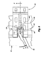
- the mounting bracket 30 is shown positioned to receive the headrail 32 with Fig. 10 showing the headrail having been advanced partially onto the mounting bracket so that the lead bar 72 of the slide plate 68 is inserted into the pocket 50 in the headrail between the rib spacer 44 and the support arm 46.
- the front bevel 82 on the bevel head 80 has engaged and passed by the rear ledge 40 of the top wall 38. The engagement of the front bevel with the rear ledge cams the bevel head downwardly into the position of Fig. 10 .
- Fig. 10 the front bevel 82 on the bevel head 80 has engaged and passed by the rear ledge 40 of the top wall 38. The engagement of the front bevel with the rear ledge cams the bevel head downwardly into the position of Fig. 10 .
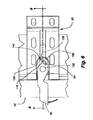
- the headrail is shown fully advanced onto the bracket in a neutral position where it will be appreciated the bevel head is positioned immediately in front of the bevel 42 on the rear ledge 40 of the top wall of the headrail.
- the rear bevel surface 84 on the catch arm 76 is engaged with the bevel 42 on the top wall of the headrail so that the headrail is temporarily but releasably secured to the bracket.
- the beveled engagement of the bevel 42 on the top wall with the rear bevel 84 on the catch arm would cam the catch arm downwardly as seen in Fig. 10 which would allow the headrail to be released from the bracket with a predetermined amount of force.
- the catch arm can be depressed from the position of Fig. 9 even though the slide-lock bar 104 is positioned therebeneath because both elements are somewhat flexible.
- the lock lever 122 can be pivoted into the position of Fig. 3 , which as mentioned previously, causes the slide lock bar 104 to move forwardly relative to the base 54 and as seen in Fig. 7 , this extreme forward limited movement of the slide-lock bar causes the paddle head 106 to overlie the lip 48 on the support arm 46 of the headrail which prevents the slide-lock bar and the overlying catch arm 76 from being pivoted downwardly.
- the catch arm cannot pivot downwardly, the headrail is prevented from removal from the mounting bracket due to the engagement of the bevel surfaces 42 and 84.
- the lock lever 122 is simply pivoted into alignment with the base 54 as shown in Fig. 4 causing the slide-lock bar 104 to be retracted further into the base so that the paddle head 106 no longer overlies the lip 48 of the support arm 46 whereby upon an outward pull on the headrail, the beveled engagement of the surfaces 42 and 84 will cause the catch arm 76 to pivot downwardly with the slide-lock bar as in Fig. 10 permitting removal of the headrail from the support bracket.
- the transverse profile of the headrail 32 is continuous along the length of the headrail so that any number of support brackets 30 can be positioned for receipt of the headrail.
- Each support bracket would be operated similarly to remove the headrail from the support bracket or to permit its mounting.
- the gripping rib 126 on the lock lever protrudes forwardly from the front wall 34 of the headrail 32 a sufficient distance to allow an operator to grip the lock lever and move it between locking and release positions.
- the lock lever can be made of a clear plastic material so as to be less visible for aesthetic purposes.
- FIG. 29-32 An alternative embodiment 142 of the bracket is shown in Figs. 29-32 and is substantially similar to the first-described bracket 30, so that corresponding parts of the bracket have been shown with the same reference numerals.
- the push-pull slot 132 of the first-disclosed embodiment which was slightly arcuate in configuration, has been replaced with a generally L-shaped push-pull slot 144 defining detents 146 and 148 at opposite ends of the L-shaped slot for releasably retaining the guide pin 116 in either the locking position of Figs. 29 and 30 or the release position of Figs. 31 and 32 .
- a horizontally disposed compression spring 150 has been provided with its rear end seated and supported on a horizontal pin 152 disposed on a vertical wall 154 of the bracket forwardly of the downturned back wall 156 as seen in Figs. 30 and 32 .
- the opposite end of the compression spring is received and seated in a recess 156 formed in the rear wall of the block-like base 158 on which the guide pin 116 is formed.
- the compression spring therefore, biases the slide-lock bar 104 in a forward direction, even though the bias can be overcome by pivotal movement of the lock lever 96 between the locking and release positions, which causes the guide pin 116 to be cammed along the L-shaped push-pull slot 144.
- the lock lever 96 can therefore be positively, but releasably, positioned in either the locking position of Fig. 29 or the release position of Fig. 31 , and the guide pin actually snaps into one of the detents at the ends of the push-pull slot giving an audible notification that the lock lever is in the locking or release position.
- the lock lever 96 can be seen to have, at an intermediate location along its length, a downwardly projecting boss 160 integrally formed thereon.
- the boss is at an elevation within the bracket 142 to engage the leading edge 162 of the ledge 40 on the head rail 32 as the bracket is being mounted on the head rail 32.
- the ledge 40 projects into the bracket ( Figs. 30 and 32 ) so the ledge 40 engages the boss on the lock lever.
- the boss is offset laterally from the pivot 94 of the lever arm so that when the lock lever is in the release position of Fig.
- the lock lever 96 When removing the bracket 142 from the head rail 32, the lock lever 96 is manually moved from the locking position of Fig. 33 to the release position of Fig. 34 , which causes the boss 160 on the lock lever to force the bracket away from the ledge 40 on the head rail, thereby releasing the bracket from the head rail and in doing so, the guide pin 116 snaps into the other detent 148 in the push-pull slot 144, again giving an audible signal that the bracket is free for removal from the head rail. Movement of the lock lever from its locking position to its release position, of course, is manually done by an operator.
- the bracket is identical to the previously described bracket and functions the same in releasably securing the bracket to a head rail as previously described.
Landscapes
- Engineering & Computer Science (AREA)
- Structural Engineering (AREA)
- Architecture (AREA)
- Civil Engineering (AREA)
- Blinds (AREA)
- Connection Of Plates (AREA)
- Curtains And Furnishings For Windows Or Doors (AREA)
- Operating, Guiding And Securing Of Roll- Type Closing Members (AREA)
Applications Claiming Priority (2)
| Application Number | Priority Date | Filing Date | Title |
|---|---|---|---|
| US11/683,625 US7637302B2 (en) | 2005-06-30 | 2007-03-08 | Lock lever mounting bracket for headrails on coverings for architectural openings |
| PCT/US2008/056013 WO2008109729A1 (en) | 2007-03-08 | 2008-03-06 | Lock lever mounting bracket for headrails on coverings for architectural openings |
Publications (3)
| Publication Number | Publication Date |
|---|---|
| EP2115237A1 EP2115237A1 (en) | 2009-11-11 |
| EP2115237A4 EP2115237A4 (en) | 2014-06-11 |
| EP2115237B1 true EP2115237B1 (en) | 2015-05-27 |
Family
ID=39797987
Family Applications (1)
| Application Number | Title | Priority Date | Filing Date |
|---|---|---|---|
| EP08731512.3A Not-in-force EP2115237B1 (en) | 2007-03-08 | 2008-03-06 | Fixation for a headrail of a shading device |
Country Status (9)
| Country | Link |
|---|---|
| US (1) | US7637302B2 (da) |
| EP (1) | EP2115237B1 (da) |
| KR (2) | KR101678047B1 (da) |
| CN (1) | CN101680229B (da) |
| AU (1) | AU2008222747C1 (da) |
| CA (1) | CA2677906C (da) |
| DK (1) | DK2115237T3 (da) |
| ES (1) | ES2545480T3 (da) |
| WO (1) | WO2008109729A1 (da) |
Families Citing this family (16)
| Publication number | Priority date | Publication date | Assignee | Title |
|---|---|---|---|---|
| US7637302B2 (en) | 2005-06-30 | 2009-12-29 | Hunter Douglas Inc. | Lock lever mounting bracket for headrails on coverings for architectural openings |
| US7516771B2 (en) * | 2005-06-30 | 2009-04-14 | Hunter Douglas Inc. | Lock lever mounting bracket for headrails on coverings for architectural openings |
| USD632118S1 (en) * | 2009-05-15 | 2011-02-08 | Designed Blinds Australia Pty Ltd | Overlapping roller blind system |
| DE102010001106A1 (de) | 2010-01-21 | 2011-07-28 | Hunter Douglas Industries Switzerland Gmbh | Halter für eine Tragschiene einer Verschattungsanlage sowie Anordnung aus einer Tragschiene und einem Halter |
| US20130098561A1 (en) * | 2011-10-19 | 2013-04-25 | Homerun Holdings Corporation | Pivoting Valance System for Shades or Blinds and a Method for Pivoting a Valance |
| US9119497B2 (en) * | 2012-05-28 | 2015-09-01 | Carol SANCHUK | Window treatment mounting assembly |
| AU2014268200A1 (en) * | 2014-11-26 | 2016-06-09 | Infinity Retractable Screens Pty Ltd | Mounting arrangement |
| USD829467S1 (en) * | 2015-11-24 | 2018-10-02 | Kvadrat A/S | Roller blind |
| US10221621B2 (en) * | 2016-01-15 | 2019-03-05 | Crestron Electronics, Inc. | Roller shade latching apparatus |
| US20190029456A1 (en) * | 2017-07-31 | 2019-01-31 | Randall Hinkle | Window shade mount |
| DK201770846A1 (da) * | 2017-11-10 | 2019-05-21 | Vkr Holding A/S | Screening arrangement with improved mounting bracket and end piece, window with such a mounting bracket and method of installing and uninstalling a screening arrangement in the window |
| DK179835B1 (da) | 2017-11-10 | 2019-07-26 | Vkr Holding A/S | A method for determining a fully extended position of a screening body of a screening device |
| WO2022076282A1 (en) * | 2020-10-07 | 2022-04-14 | Hunter Douglas, Inc. | Bracket for coupling a cassette/headrail of an architectural-structure covering to an underlying architecture structure |
| US11828481B2 (en) | 2020-10-16 | 2023-11-28 | Honeywell International, Inc. | Building controller with adaptable mount |
| EP4433681A1 (en) * | 2021-11-16 | 2024-09-25 | Lutron Technology Company LLC | Motorized window treatment |
| US12042076B1 (en) * | 2023-03-09 | 2024-07-23 | Arlinea Industries Co. | Combination structure of decorative curtain rod and track |
Family Cites Families (39)
| Publication number | Priority date | Publication date | Assignee | Title |
|---|---|---|---|---|
| US2520272A (en) * | 1945-02-12 | 1950-08-29 | Vertical Venetian Blind Compan | Vertical blind |
| US3030060A (en) * | 1960-01-15 | 1962-04-17 | Breuer Karl | Curtain rod mounting devices |
| US3029465A (en) * | 1960-03-25 | 1962-04-17 | Graber Mfg Company Inc | Drapery fixture |
| US3291194A (en) * | 1963-12-05 | 1966-12-13 | Clarence M Kirtley | Clamp and housing apparatus |
| US4114233A (en) * | 1976-10-07 | 1978-09-19 | Val-Trac Incorporated | Window trim assembly |
| GB2137270B (en) * | 1983-03-29 | 1986-01-29 | Hunter Douglas Ind Bv | A support bracket for a venetian blind headrail |
| KR920003767B1 (ko) * | 1988-06-28 | 1992-05-14 | 마쓰시다 덴끼 산교오 가부시끼가이샤 | 배연(排煙) 정화장치 |
| US4938443A (en) * | 1988-12-02 | 1990-07-03 | Carey-Mcfall Corporation | Venetian blind installation bracket |
| USD329294S (en) * | 1989-08-02 | 1992-09-08 | Kenney Manufacturing Company | Beveled headrail |
| GB8920965D0 (en) * | 1989-09-15 | 1989-11-01 | Hallis Hudson Group Limited | A mounting bracket |
| US5044589A (en) * | 1990-06-25 | 1991-09-03 | Milne Fred W | Vertical wall covering bracket assembly |
| US5131616A (en) * | 1990-10-22 | 1992-07-21 | Graber Industries, Inc. | Bracket for adjustably supporting a headrail |
| US5186426A (en) * | 1991-12-10 | 1993-02-16 | Tachikawa Corporation | Rail attachment structure |
| US5515901A (en) * | 1992-02-03 | 1996-05-14 | Dsh Inc. | Fascia for bifold doors |
| CA2092648C (en) * | 1992-03-18 | 1995-12-12 | Richard N. Anderson | Bracket and headrail combination for a blind |
| US5195570A (en) * | 1992-05-14 | 1993-03-23 | Norbert Marocco | Bracket for window covering assembly |
| CN2125331U (zh) * | 1992-06-06 | 1992-12-23 | 林辉星 | 窗帘上轨安装架 |
| DE9302386U1 (de) * | 1993-02-18 | 1993-04-08 | Festo KG, 7300 Esslingen | Für Demonstrations- und/oder Schulungszwecke verwendbares Funktionselement |
| US5584459A (en) * | 1995-03-13 | 1996-12-17 | Meyer; George | Bracket system for hanging window cover frame |
| US5626177A (en) * | 1995-06-07 | 1997-05-06 | Hunter Douglas Inc. | Control and suspension system for a vertical vane covering for architectural openings |
| DE19804860C1 (de) * | 1998-02-09 | 1999-08-26 | Dorma Gmbh & Co Kg | Gehäuse, insbesondere für automatische Türantriebe |
| CA2276071C (en) * | 1998-06-22 | 2007-09-04 | Hunter Douglas Inc. | Remote control operating system and support structure for a retractable covering for an architectural opening |
| DE60000356T2 (de) * | 1999-02-05 | 2003-01-23 | Turnils Ab, Alingsaas | Haltebügel |
| US6186457B1 (en) * | 1999-03-03 | 2001-02-13 | Gilmore Enterprises | Adjustable mounting bracket |
| US6626177B1 (en) * | 1999-06-18 | 2003-09-30 | Saeed Ziaee | Nasal mask |
| US6202967B1 (en) * | 1999-06-23 | 2001-03-20 | Rollease, Inc. | Zero clearance bracket and headrail |
| US6293330B1 (en) * | 1999-08-26 | 2001-09-25 | Newell Window Furnishings, Inc. | Universal head rail |
| US6382296B1 (en) | 2001-03-23 | 2002-05-07 | Ren Judkins | Headrail and bracket system for window coverings |
| KR200269675Y1 (ko) | 2001-12-27 | 2002-03-22 | 권향미 | 롤브라인드용 측면 고정구 착탈장치 |
| US6561475B1 (en) * | 2002-01-11 | 2003-05-13 | Lung-Tang Chuang | Structure for locating curtain traverse rod |
| US6585208B1 (en) * | 2002-01-25 | 2003-07-01 | Hunter Douglas Inc. | Universal bracket for mounting coverings for architectural openings |
| US7240715B2 (en) * | 2003-12-24 | 2007-07-10 | Hunter Douglas Inc. | Limit stop for coverings for architectural openings |
| US7134469B2 (en) * | 2004-05-17 | 2006-11-14 | Hunter Douglas Inc. | Headrail mounting system |
| ATE557157T1 (de) | 2004-07-23 | 2012-05-15 | Hunter Douglas Ind Bv | Verstellbare halterung |
| US7284736B2 (en) * | 2004-08-02 | 2007-10-23 | Hunter Douglas Industries Bv | Mounting bracket |
| US7360573B2 (en) * | 2005-03-03 | 2008-04-22 | Teh Yor Co., Ltd. | Securement insert for a head rail |
| US7637302B2 (en) | 2005-06-30 | 2009-12-29 | Hunter Douglas Inc. | Lock lever mounting bracket for headrails on coverings for architectural openings |
| US7516771B2 (en) * | 2005-06-30 | 2009-04-14 | Hunter Douglas Inc. | Lock lever mounting bracket for headrails on coverings for architectural openings |
| US7367536B1 (en) * | 2005-09-02 | 2008-05-06 | Hunter Douglas Inc. | Mounting bracket for a covering for architectural openings |
-
2007
- 2007-03-08 US US11/683,625 patent/US7637302B2/en active Active
-
2008
- 2008-03-06 KR KR1020157033619A patent/KR101678047B1/ko active Active
- 2008-03-06 DK DK08731512.3T patent/DK2115237T3/da active
- 2008-03-06 WO PCT/US2008/056013 patent/WO2008109729A1/en not_active Ceased
- 2008-03-06 ES ES08731512.3T patent/ES2545480T3/es active Active
- 2008-03-06 EP EP08731512.3A patent/EP2115237B1/en not_active Not-in-force
- 2008-03-06 CA CA2677906A patent/CA2677906C/en active Active
- 2008-03-06 KR KR1020097020973A patent/KR101573426B1/ko not_active Expired - Fee Related
- 2008-03-06 AU AU2008222747A patent/AU2008222747C1/en not_active Ceased
- 2008-03-06 CN CN2008800075547A patent/CN101680229B/zh not_active Expired - Fee Related
Also Published As
| Publication number | Publication date |
|---|---|
| CA2677906A1 (en) | 2008-09-12 |
| CN101680229A (zh) | 2010-03-24 |
| AU2008222747C1 (en) | 2013-08-15 |
| AU2008222747A1 (en) | 2008-09-12 |
| DK2115237T3 (da) | 2015-09-07 |
| KR20090122373A (ko) | 2009-11-27 |
| US7637302B2 (en) | 2009-12-29 |
| WO2008109729A1 (en) | 2008-09-12 |
| KR101678047B1 (ko) | 2016-11-21 |
| KR101573426B1 (ko) | 2015-12-01 |
| EP2115237A1 (en) | 2009-11-11 |
| AU2008222747B2 (en) | 2013-02-28 |
| CA2677906C (en) | 2015-04-14 |
| KR20150140393A (ko) | 2015-12-15 |
| EP2115237A4 (en) | 2014-06-11 |
| ES2545480T3 (es) | 2015-09-11 |
| US20070144682A1 (en) | 2007-06-28 |
| CN101680229B (zh) | 2012-11-07 |
Similar Documents
| Publication | Publication Date | Title |
|---|---|---|
| AU2008222747C1 (en) | Lock lever mounting bracket for headrails on coverings for architectural openings | |
| US7516771B2 (en) | Lock lever mounting bracket for headrails on coverings for architectural openings | |
| US7134469B2 (en) | Headrail mounting system | |
| EP1783321B1 (en) | Roller stop for coverings for architectural openings | |
| US6382296B1 (en) | Headrail and bracket system for window coverings | |
| US8235430B2 (en) | Window vent stop with flexible side engagement pieces | |
| US7322619B2 (en) | Integrated lock and tilt-latch mechanism for a sliding window | |
| CA2864861C (en) | Architectural covering with repositionable handle assembly | |
| US6322029B1 (en) | Installation bracket | |
| US20070089841A1 (en) | Head rail and support bracket | |
| US20070175594A1 (en) | Coverings for architectural openings with cord lock | |
| CN218092579U (zh) | 推拉窗和工程机械驾驶室 | |
| JP2907669B2 (ja) | スクリ−ン取り付け用ブラケット | |
| US20040226667A1 (en) | Mounting bracket and headrail for a window covering | |
| EP1520951B1 (en) | A sliding device, a window having such a sliding device and a method for mounting a sash in such a window | |
| JP2743244B2 (ja) | 回動窓 | |
| JP3884679B2 (ja) | 開閉装置 | |
| EP1026360B1 (en) | Installation bracket | |
| JPS626216Y2 (da) | ||
| AU2021209316A1 (en) | A window chain winder | |
| EP1512827A2 (en) | Bracket | |
| JP2004084416A (ja) | 開閉装置および後付鍵ユニット | |
| JP2004215768A (ja) | 掛止用フック |
Legal Events
| Date | Code | Title | Description |
|---|---|---|---|
| PUAI | Public reference made under article 153(3) epc to a published international application that has entered the european phase |
Free format text: ORIGINAL CODE: 0009012 |
|
| 17P | Request for examination filed |
Effective date: 20090811 |
|
| AK | Designated contracting states |
Kind code of ref document: A1 Designated state(s): AT BE BG CH CY CZ DE DK EE ES FI FR GB GR HR HU IE IS IT LI LT LU LV MC MT NL NO PL PT RO SE SI SK TR |
|
| DAX | Request for extension of the european patent (deleted) | ||
| RAP1 | Party data changed (applicant data changed or rights of an application transferred) |
Owner name: HUNTER DOUGLAS INC. |
|
| REG | Reference to a national code |
Ref country code: DE Ref legal event code: R079 Ref document number: 602008038331 Country of ref document: DE Free format text: PREVIOUS MAIN CLASS: E04F0010000000 Ipc: E06B0009323000 |
|
| A4 | Supplementary search report drawn up and despatched |
Effective date: 20140509 |
|
| RIC1 | Information provided on ipc code assigned before grant |
Ipc: E06B 9/323 20060101AFI20140502BHEP |
|
| GRAP | Despatch of communication of intention to grant a patent |
Free format text: ORIGINAL CODE: EPIDOSNIGR1 |
|
| INTG | Intention to grant announced |
Effective date: 20141217 |
|
| GRAS | Grant fee paid |
Free format text: ORIGINAL CODE: EPIDOSNIGR3 |
|
| GRAA | (expected) grant |
Free format text: ORIGINAL CODE: 0009210 |
|
| AK | Designated contracting states |
Kind code of ref document: B1 Designated state(s): AT BE BG CH CY CZ DE DK EE ES FI FR GB GR HR HU IE IS IT LI LT LU LV MC MT NL NO PL PT RO SE SI SK TR |
|
| REG | Reference to a national code |
Ref country code: GB Ref legal event code: FG4D |
|
| REG | Reference to a national code |
Ref country code: CH Ref legal event code: EP |
|
| REG | Reference to a national code |
Ref country code: AT Ref legal event code: REF Ref document number: 728970 Country of ref document: AT Kind code of ref document: T Effective date: 20150615 |
|
| REG | Reference to a national code |
Ref country code: IE Ref legal event code: FG4D |
|
| REG | Reference to a national code |
Ref country code: DE Ref legal event code: R096 Ref document number: 602008038331 Country of ref document: DE |
|
| REG | Reference to a national code |
Ref country code: SE Ref legal event code: TRGR |
|
| REG | Reference to a national code |
Ref country code: NL Ref legal event code: T3 |
|
| REG | Reference to a national code |
Ref country code: DK Ref legal event code: T3 Effective date: 20150831 |
|
| REG | Reference to a national code |
Ref country code: ES Ref legal event code: FG2A Ref document number: 2545480 Country of ref document: ES Kind code of ref document: T3 Effective date: 20150911 |
|
| REG | Reference to a national code |
Ref country code: AT Ref legal event code: MK05 Ref document number: 728970 Country of ref document: AT Kind code of ref document: T Effective date: 20150527 |
|
| REG | Reference to a national code |
Ref country code: LT Ref legal event code: MG4D |
|
| PG25 | Lapsed in a contracting state [announced via postgrant information from national office to epo] |
Ref country code: HR Free format text: LAPSE BECAUSE OF FAILURE TO SUBMIT A TRANSLATION OF THE DESCRIPTION OR TO PAY THE FEE WITHIN THE PRESCRIBED TIME-LIMIT Effective date: 20150527 Ref country code: FI Free format text: LAPSE BECAUSE OF FAILURE TO SUBMIT A TRANSLATION OF THE DESCRIPTION OR TO PAY THE FEE WITHIN THE PRESCRIBED TIME-LIMIT Effective date: 20150527 Ref country code: PT Free format text: LAPSE BECAUSE OF FAILURE TO SUBMIT A TRANSLATION OF THE DESCRIPTION OR TO PAY THE FEE WITHIN THE PRESCRIBED TIME-LIMIT Effective date: 20150928 Ref country code: NO Free format text: LAPSE BECAUSE OF FAILURE TO SUBMIT A TRANSLATION OF THE DESCRIPTION OR TO PAY THE FEE WITHIN THE PRESCRIBED TIME-LIMIT Effective date: 20150827 Ref country code: LT Free format text: LAPSE BECAUSE OF FAILURE TO SUBMIT A TRANSLATION OF THE DESCRIPTION OR TO PAY THE FEE WITHIN THE PRESCRIBED TIME-LIMIT Effective date: 20150527 |
|
| PG25 | Lapsed in a contracting state [announced via postgrant information from national office to epo] |
Ref country code: LV Free format text: LAPSE BECAUSE OF FAILURE TO SUBMIT A TRANSLATION OF THE DESCRIPTION OR TO PAY THE FEE WITHIN THE PRESCRIBED TIME-LIMIT Effective date: 20150527 Ref country code: AT Free format text: LAPSE BECAUSE OF FAILURE TO SUBMIT A TRANSLATION OF THE DESCRIPTION OR TO PAY THE FEE WITHIN THE PRESCRIBED TIME-LIMIT Effective date: 20150527 Ref country code: BG Free format text: LAPSE BECAUSE OF FAILURE TO SUBMIT A TRANSLATION OF THE DESCRIPTION OR TO PAY THE FEE WITHIN THE PRESCRIBED TIME-LIMIT Effective date: 20150827 Ref country code: IS Free format text: LAPSE BECAUSE OF FAILURE TO SUBMIT A TRANSLATION OF THE DESCRIPTION OR TO PAY THE FEE WITHIN THE PRESCRIBED TIME-LIMIT Effective date: 20150927 Ref country code: GR Free format text: LAPSE BECAUSE OF FAILURE TO SUBMIT A TRANSLATION OF THE DESCRIPTION OR TO PAY THE FEE WITHIN THE PRESCRIBED TIME-LIMIT Effective date: 20150828 |
|
| PG25 | Lapsed in a contracting state [announced via postgrant information from national office to epo] |
Ref country code: EE Free format text: LAPSE BECAUSE OF FAILURE TO SUBMIT A TRANSLATION OF THE DESCRIPTION OR TO PAY THE FEE WITHIN THE PRESCRIBED TIME-LIMIT Effective date: 20150527 |
|
| REG | Reference to a national code |
Ref country code: FR Ref legal event code: PLFP Year of fee payment: 9 |
|
| PG25 | Lapsed in a contracting state [announced via postgrant information from national office to epo] |
Ref country code: CZ Free format text: LAPSE BECAUSE OF FAILURE TO SUBMIT A TRANSLATION OF THE DESCRIPTION OR TO PAY THE FEE WITHIN THE PRESCRIBED TIME-LIMIT Effective date: 20150527 Ref country code: PL Free format text: LAPSE BECAUSE OF FAILURE TO SUBMIT A TRANSLATION OF THE DESCRIPTION OR TO PAY THE FEE WITHIN THE PRESCRIBED TIME-LIMIT Effective date: 20150527 Ref country code: RO Free format text: LAPSE BECAUSE OF NON-PAYMENT OF DUE FEES Effective date: 20150527 Ref country code: SK Free format text: LAPSE BECAUSE OF FAILURE TO SUBMIT A TRANSLATION OF THE DESCRIPTION OR TO PAY THE FEE WITHIN THE PRESCRIBED TIME-LIMIT Effective date: 20150527 |
|
| REG | Reference to a national code |
Ref country code: DE Ref legal event code: R097 Ref document number: 602008038331 Country of ref document: DE |
|
| PLBE | No opposition filed within time limit |
Free format text: ORIGINAL CODE: 0009261 |
|
| STAA | Information on the status of an ep patent application or granted ep patent |
Free format text: STATUS: NO OPPOSITION FILED WITHIN TIME LIMIT |
|
| PG25 | Lapsed in a contracting state [announced via postgrant information from national office to epo] |
Ref country code: IT Free format text: LAPSE BECAUSE OF FAILURE TO SUBMIT A TRANSLATION OF THE DESCRIPTION OR TO PAY THE FEE WITHIN THE PRESCRIBED TIME-LIMIT Effective date: 20150527 |
|
| 26N | No opposition filed |
Effective date: 20160301 |
|
| PG25 | Lapsed in a contracting state [announced via postgrant information from national office to epo] |
Ref country code: SI Free format text: LAPSE BECAUSE OF FAILURE TO SUBMIT A TRANSLATION OF THE DESCRIPTION OR TO PAY THE FEE WITHIN THE PRESCRIBED TIME-LIMIT Effective date: 20150527 |
|
| PG25 | Lapsed in a contracting state [announced via postgrant information from national office to epo] |
Ref country code: BE Free format text: LAPSE BECAUSE OF FAILURE TO SUBMIT A TRANSLATION OF THE DESCRIPTION OR TO PAY THE FEE WITHIN THE PRESCRIBED TIME-LIMIT Effective date: 20150527 |
|
| PG25 | Lapsed in a contracting state [announced via postgrant information from national office to epo] |
Ref country code: MC Free format text: LAPSE BECAUSE OF FAILURE TO SUBMIT A TRANSLATION OF THE DESCRIPTION OR TO PAY THE FEE WITHIN THE PRESCRIBED TIME-LIMIT Effective date: 20150527 Ref country code: LU Free format text: LAPSE BECAUSE OF FAILURE TO SUBMIT A TRANSLATION OF THE DESCRIPTION OR TO PAY THE FEE WITHIN THE PRESCRIBED TIME-LIMIT Effective date: 20160306 |
|
| REG | Reference to a national code |
Ref country code: CH Ref legal event code: PL |
|
| REG | Reference to a national code |
Ref country code: IE Ref legal event code: MM4A |
|
| PG25 | Lapsed in a contracting state [announced via postgrant information from national office to epo] |
Ref country code: IE Free format text: LAPSE BECAUSE OF NON-PAYMENT OF DUE FEES Effective date: 20160306 Ref country code: CH Free format text: LAPSE BECAUSE OF NON-PAYMENT OF DUE FEES Effective date: 20160331 Ref country code: LI Free format text: LAPSE BECAUSE OF NON-PAYMENT OF DUE FEES Effective date: 20160331 |
|
| REG | Reference to a national code |
Ref country code: FR Ref legal event code: PLFP Year of fee payment: 10 |
|
| PG25 | Lapsed in a contracting state [announced via postgrant information from national office to epo] |
Ref country code: MT Free format text: LAPSE BECAUSE OF FAILURE TO SUBMIT A TRANSLATION OF THE DESCRIPTION OR TO PAY THE FEE WITHIN THE PRESCRIBED TIME-LIMIT Effective date: 20150527 |
|
| REG | Reference to a national code |
Ref country code: FR Ref legal event code: PLFP Year of fee payment: 11 |
|
| PG25 | Lapsed in a contracting state [announced via postgrant information from national office to epo] |
Ref country code: CY Free format text: LAPSE BECAUSE OF FAILURE TO SUBMIT A TRANSLATION OF THE DESCRIPTION OR TO PAY THE FEE WITHIN THE PRESCRIBED TIME-LIMIT Effective date: 20150527 Ref country code: HU Free format text: LAPSE BECAUSE OF FAILURE TO SUBMIT A TRANSLATION OF THE DESCRIPTION OR TO PAY THE FEE WITHIN THE PRESCRIBED TIME-LIMIT; INVALID AB INITIO Effective date: 20080306 |
|
| PG25 | Lapsed in a contracting state [announced via postgrant information from national office to epo] |
Ref country code: TR Free format text: LAPSE BECAUSE OF FAILURE TO SUBMIT A TRANSLATION OF THE DESCRIPTION OR TO PAY THE FEE WITHIN THE PRESCRIBED TIME-LIMIT Effective date: 20150527 Ref country code: MT Free format text: LAPSE BECAUSE OF FAILURE TO SUBMIT A TRANSLATION OF THE DESCRIPTION OR TO PAY THE FEE WITHIN THE PRESCRIBED TIME-LIMIT Effective date: 20160331 |
|
| PGFP | Annual fee paid to national office [announced via postgrant information from national office to epo] |
Ref country code: GB Payment date: 20220203 Year of fee payment: 15 Ref country code: DK Payment date: 20220309 Year of fee payment: 15 Ref country code: DE Payment date: 20220203 Year of fee payment: 15 |
|
| PGFP | Annual fee paid to national office [announced via postgrant information from national office to epo] |
Ref country code: SE Payment date: 20220210 Year of fee payment: 15 Ref country code: NL Payment date: 20220215 Year of fee payment: 15 Ref country code: FR Payment date: 20220209 Year of fee payment: 15 |
|
| PGFP | Annual fee paid to national office [announced via postgrant information from national office to epo] |
Ref country code: ES Payment date: 20220405 Year of fee payment: 15 |
|
| P01 | Opt-out of the competence of the unified patent court (upc) registered |
Effective date: 20230331 |
|
| REG | Reference to a national code |
Ref country code: DE Ref legal event code: R119 Ref document number: 602008038331 Country of ref document: DE |
|
| REG | Reference to a national code |
Ref country code: SE Ref legal event code: EUG |
|
| REG | Reference to a national code |
Ref country code: DK Ref legal event code: EBP Effective date: 20230331 |
|
| REG | Reference to a national code |
Ref country code: NL Ref legal event code: MM Effective date: 20230401 |
|
| GBPC | Gb: european patent ceased through non-payment of renewal fee |
Effective date: 20230306 |
|
| PG25 | Lapsed in a contracting state [announced via postgrant information from national office to epo] |
Ref country code: NL Free format text: LAPSE BECAUSE OF NON-PAYMENT OF DUE FEES Effective date: 20230401 |
|
| PG25 | Lapsed in a contracting state [announced via postgrant information from national office to epo] |
Ref country code: GB Free format text: LAPSE BECAUSE OF NON-PAYMENT OF DUE FEES Effective date: 20230306 |
|
| PG25 | Lapsed in a contracting state [announced via postgrant information from national office to epo] |
Ref country code: SE Free format text: LAPSE BECAUSE OF NON-PAYMENT OF DUE FEES Effective date: 20230307 Ref country code: GB Free format text: LAPSE BECAUSE OF NON-PAYMENT OF DUE FEES Effective date: 20230306 Ref country code: FR Free format text: LAPSE BECAUSE OF NON-PAYMENT OF DUE FEES Effective date: 20230331 Ref country code: DE Free format text: LAPSE BECAUSE OF NON-PAYMENT OF DUE FEES Effective date: 20231003 |
|
| PG25 | Lapsed in a contracting state [announced via postgrant information from national office to epo] |
Ref country code: ES Free format text: LAPSE BECAUSE OF NON-PAYMENT OF DUE FEES Effective date: 20230307 |
|
| REG | Reference to a national code |
Ref country code: ES Ref legal event code: FD2A Effective date: 20240426 |
|
| PG25 | Lapsed in a contracting state [announced via postgrant information from national office to epo] |
Ref country code: ES Free format text: LAPSE BECAUSE OF NON-PAYMENT OF DUE FEES Effective date: 20230307 Ref country code: DK Free format text: LAPSE BECAUSE OF NON-PAYMENT OF DUE FEES Effective date: 20230331 |