EP2114780B1 - Keg assembly and chime for being fixed to the bottom of a keg - Google Patents
Keg assembly and chime for being fixed to the bottom of a keg Download PDFInfo
- Publication number
- EP2114780B1 EP2114780B1 EP08716814A EP08716814A EP2114780B1 EP 2114780 B1 EP2114780 B1 EP 2114780B1 EP 08716814 A EP08716814 A EP 08716814A EP 08716814 A EP08716814 A EP 08716814A EP 2114780 B1 EP2114780 B1 EP 2114780B1
- Authority
- EP
- European Patent Office
- Prior art keywords
- keg
- chime
- inner hub
- fixation
- skirt
- Prior art date
- Legal status (The legal status is an assumption and is not a legal conclusion. Google has not performed a legal analysis and makes no representation as to the accuracy of the status listed.)
- Not-in-force
Links
- 230000002093 peripheral effect Effects 0.000 claims description 12
- 239000012815 thermoplastic material Substances 0.000 claims description 6
- 230000000295 complement effect Effects 0.000 claims description 4
- 238000000071 blow moulding Methods 0.000 description 11
- 239000004033 plastic Substances 0.000 description 10
- 229920003023 plastic Polymers 0.000 description 10
- 238000004519 manufacturing process Methods 0.000 description 6
- 229920001169 thermoplastic Polymers 0.000 description 6
- 239000004416 thermosoftening plastic Substances 0.000 description 6
- 238000000034 method Methods 0.000 description 5
- 238000004064 recycling Methods 0.000 description 5
- 230000000712 assembly Effects 0.000 description 4
- 238000000429 assembly Methods 0.000 description 4
- 238000001125 extrusion Methods 0.000 description 4
- 229920000139 polyethylene terephthalate Polymers 0.000 description 4
- 239000005020 polyethylene terephthalate Substances 0.000 description 4
- 230000008901 benefit Effects 0.000 description 3
- 239000011521 glass Substances 0.000 description 3
- 229920001903 high density polyethylene Polymers 0.000 description 3
- 239000004700 high-density polyethylene Substances 0.000 description 3
- 238000002347 injection Methods 0.000 description 3
- 239000007924 injection Substances 0.000 description 3
- 239000007788 liquid Substances 0.000 description 3
- 230000008569 process Effects 0.000 description 3
- 241000239290 Araneae Species 0.000 description 2
- 239000011324 bead Substances 0.000 description 2
- 238000006073 displacement reaction Methods 0.000 description 2
- 239000007789 gas Substances 0.000 description 2
- 239000000463 material Substances 0.000 description 2
- 230000007704 transition Effects 0.000 description 2
- XLYOFNOQVPJJNP-UHFFFAOYSA-N water Substances O XLYOFNOQVPJJNP-UHFFFAOYSA-N 0.000 description 2
- CDBYLPFSWZWCQE-UHFFFAOYSA-L Sodium Carbonate Chemical compound [Na+].[Na+].[O-]C([O-])=O CDBYLPFSWZWCQE-UHFFFAOYSA-L 0.000 description 1
- 230000009471 action Effects 0.000 description 1
- QVGXLLKOCUKJST-UHFFFAOYSA-N atomic oxygen Chemical compound [O] QVGXLLKOCUKJST-UHFFFAOYSA-N 0.000 description 1
- 235000013405 beer Nutrition 0.000 description 1
- 235000013361 beverage Nutrition 0.000 description 1
- 230000015572 biosynthetic process Effects 0.000 description 1
- 238000007664 blowing Methods 0.000 description 1
- 230000001143 conditioned effect Effects 0.000 description 1
- 230000009133 cooperative interaction Effects 0.000 description 1
- 238000002425 crystallisation Methods 0.000 description 1
- 230000008025 crystallization Effects 0.000 description 1
- 230000001419 dependent effect Effects 0.000 description 1
- 230000009977 dual effect Effects 0.000 description 1
- 230000000694 effects Effects 0.000 description 1
- 238000005516 engineering process Methods 0.000 description 1
- 238000010101 extrusion blow moulding Methods 0.000 description 1
- 239000000796 flavoring agent Substances 0.000 description 1
- 235000019634 flavors Nutrition 0.000 description 1
- 230000009477 glass transition Effects 0.000 description 1
- 238000010102 injection blow moulding Methods 0.000 description 1
- 230000002452 interceptive effect Effects 0.000 description 1
- 239000000155 melt Substances 0.000 description 1
- 238000000465 moulding Methods 0.000 description 1
- 239000001301 oxygen Substances 0.000 description 1
- 229910052760 oxygen Inorganic materials 0.000 description 1
- 238000004806 packaging method and process Methods 0.000 description 1
- 230000035699 permeability Effects 0.000 description 1
- 229920000728 polyester Polymers 0.000 description 1
- 239000011112 polyethylene naphthalate Substances 0.000 description 1
- -1 polyethylene terephthalate Polymers 0.000 description 1
- 229920000098 polyolefin Polymers 0.000 description 1
- 230000008439 repair process Effects 0.000 description 1
- 239000012858 resilient material Substances 0.000 description 1
- 238000005096 rolling process Methods 0.000 description 1
- 238000007493 shaping process Methods 0.000 description 1
- 230000000087 stabilizing effect Effects 0.000 description 1
- 238000003860 storage Methods 0.000 description 1
- 230000008961 swelling Effects 0.000 description 1
- 230000001960 triggered effect Effects 0.000 description 1
Images



Classifications
-
- B—PERFORMING OPERATIONS; TRANSPORTING
- B65—CONVEYING; PACKING; STORING; HANDLING THIN OR FILAMENTARY MATERIAL
- B65D—CONTAINERS FOR STORAGE OR TRANSPORT OF ARTICLES OR MATERIALS, e.g. BAGS, BARRELS, BOTTLES, BOXES, CANS, CARTONS, CRATES, DRUMS, JARS, TANKS, HOPPERS, FORWARDING CONTAINERS; ACCESSORIES, CLOSURES, OR FITTINGS THEREFOR; PACKAGING ELEMENTS; PACKAGES
- B65D11/00—Containers having bodies formed by interconnecting or uniting two or more rigid, or substantially rigid, components made wholly or mainly of plastics material
- B65D11/02—Containers having bodies formed by interconnecting or uniting two or more rigid, or substantially rigid, components made wholly or mainly of plastics material of curved cross-section
- B65D11/06—Drums or barrels
-
- B—PERFORMING OPERATIONS; TRANSPORTING
- B65—CONVEYING; PACKING; STORING; HANDLING THIN OR FILAMENTARY MATERIAL
- B65D—CONTAINERS FOR STORAGE OR TRANSPORT OF ARTICLES OR MATERIALS, e.g. BAGS, BARRELS, BOTTLES, BOXES, CANS, CARTONS, CRATES, DRUMS, JARS, TANKS, HOPPERS, FORWARDING CONTAINERS; ACCESSORIES, CLOSURES, OR FITTINGS THEREFOR; PACKAGING ELEMENTS; PACKAGES
- B65D21/00—Nestable, stackable or joinable containers; Containers of variable capacity
- B65D21/02—Containers specially shaped, or provided with fittings or attachments, to facilitate nesting, stacking, or joining together
- B65D21/0209—Containers specially shaped, or provided with fittings or attachments, to facilitate nesting, stacking, or joining together stackable or joined together one-upon-the-other in the upright or upside-down position
- B65D21/0224—Auxiliary removable stacking elements other than covers
-
- B—PERFORMING OPERATIONS; TRANSPORTING
- B65—CONVEYING; PACKING; STORING; HANDLING THIN OR FILAMENTARY MATERIAL
- B65D—CONTAINERS FOR STORAGE OR TRANSPORT OF ARTICLES OR MATERIALS, e.g. BAGS, BARRELS, BOTTLES, BOXES, CANS, CARTONS, CRATES, DRUMS, JARS, TANKS, HOPPERS, FORWARDING CONTAINERS; ACCESSORIES, CLOSURES, OR FITTINGS THEREFOR; PACKAGING ELEMENTS; PACKAGES
- B65D25/00—Details of other kinds or types of rigid or semi-rigid containers
- B65D25/20—External fittings
- B65D25/24—External fittings for spacing bases of containers from supporting surfaces, e.g. legs
-
- Y—GENERAL TAGGING OF NEW TECHNOLOGICAL DEVELOPMENTS; GENERAL TAGGING OF CROSS-SECTIONAL TECHNOLOGIES SPANNING OVER SEVERAL SECTIONS OF THE IPC; TECHNICAL SUBJECTS COVERED BY FORMER USPC CROSS-REFERENCE ART COLLECTIONS [XRACs] AND DIGESTS
- Y10—TECHNICAL SUBJECTS COVERED BY FORMER USPC
- Y10T—TECHNICAL SUBJECTS COVERED BY FORMER US CLASSIFICATION
- Y10T29/00—Metal working
- Y10T29/49—Method of mechanical manufacture
- Y10T29/4998—Combined manufacture including applying or shaping of fluent material
Definitions
- the present invention relates to kegs and to chimes provided at the bottom part of said kegs.
- a keg with bottom and top chimes usually perform several functions.
- the base chime also provides a flat base for the keg, such that this can easily be placed in an upright position.
- the top and bottom chime are designed to make kegs stackable and as such simplify transport and storage of the kegs.
- a further important function of chimes is to facilitate handling of the kegs.
- chimes are provided with a skirt that in a mounted position is situated at the periphery of the keg and that forms a rolling ring, such that when kegs are provided with bottom and top chimes, the kegs can be rolled easily when placed on their side, without the kegs sidewall touching ground.
- JP10035679 discloses a small plastic container comprising a plastic base snap fitted thereto.
- US4955492 and US4573604 disclose plastic soda bottles comprising a bottom stand for stabilizing the bottles in their standing position.
- FR775196 discloses a base made of a resilient material to be fixed to the bottom of glasses, jars, and the like.
- US2004/034918 disclose a wine glass comprising an elongated receptacle and a fixable stand of flattened conical shape of the type used in wine glasses. None of the above containers, however, are concerned with the problems encountered with large capacity containers like kegs.
- the present invention solves the above objectives by providing a keg assembly comprising a keg and a chime fixed to each other as defined in claim 1.
- the fixation between chime and keg is releasable, such that the chimes can easily be replaced when damaged.
- the fixation is achieved by a snap fit between the chime and the keg.
- a keg useful for the invention has a base that is provided with attachment means situated at a distance from the kegs peripheral sidewall, said attachment means comprising tapered side walls extending transversally from the second end and terminating in an overhanging abutment.
- a chime according to the invention comprises at least a inner hub provided with fixation means and an outer skirt that is designed to engage part of the peripheral sidewall of a keg.
- the inner hub comprises an opening circumscribed by respective free ends of a plurality of resilient tines extending radially inwardly from the inner hub.
- a keg useful in the present invention may be manufactured by providing attachment means at a base of the keg and at a distance of the kegs peripheral sidewall.
- the keg is manufactured in a thermoplastic material that is molded in a mold, whereby the attachment means are created by using a mold having a cavity defining a sump region in the that part of the mold cavity that corresponds to the base of the keg to be formed therein.
- the method further comprises inserting a rod in the mold cavity during molding, which rod extends until in the sump defining region of the mold cavity.
- Keg bottom chime 1 comprises a keg bottom finish surround 10.
- Surround 10 is specifically adapted to engage a cooperating keg bottom finish (not shown in Figures 1 and 2 , but refer instead to Figures 3 and 4 ). That engagement sustains a mutually inter-fitting secured relation to thereby at least partially secure the chime to the keg.
- the chime 1 comprises a surround 10 comprising an opening 10a, which is circumscribed by respective free ends 10d of a plurality of resilient, flexible tines 10b. Tines 10b extend radially inwardly into opening 10a, from fixed ends of said tines 10b that are rooted on a inner, preferably central hub 3.
- Chime 1 includes a "spider" 2 for engaging a bottom portion of a keg body (again, not shown in Figures 1 and 2 , refer to Figures 3 and 4 and the description that follows below), in cradled relation in the chime 1.
- the spider 2 in turn comprises the central hub 3 with a plurality of radially outwardly extending legs or spokes 4. These spokes terminate at a rim wall 5, with rim wall 5 defining one side of a channel 6 that is further bounded at the bottom thereof by a chime base 13, and surrounded on a spaced apart side by an wall surface 7a of an upstanding chime skirt 7.
- Spokes 4a, 4b, 4c and 4d have contours 14, (e.g. are scallop-shaped) to provide a stiffened girder effect.
- the upstanding chime skirt 7 supports a peripheral bead 12 adapted to engage adjacent peripheral sidewall surfaces of a secured keg body.
- Skirt 7 also includes keg body drains 9 for draining liquids accumulating between the skirt 7 and an associated keg body peripheral sidewall.
- keg assemblies according to the present invention can accumulate water or other liquids that would remain trapped between the chime and the keg when the assembly is oriented in its normal upright position, but which is permitted to drain away through these drains 9.
- bottom channel bottom 6 includes channel drains 11 for draining liquids accumulating with channel 6.
- keg assemblies according to the present invention are often washed and filled in an inverted orientation, during which time water might otherwise accumulate in the channel unless permitted to drain away through these drains.
- the keg of the present invention and assemblies comprising same are preferably closed-system kegs.
- Body 15 comprises a peripheral sidewall 17 and a base 15a.
- the base 15a having a keg body bottom finish 16, which is adapted to engage a complementary keg bottom finish surround 10 of keg bottom chime 1 illustrated in Figures 1 and 2 .
- Bottom finish 16 includes tapered side walls 16a extending proud of the periphery of the keg body 15 and terminating in an overhanging abutment 16b that is particularly suited to engage in inter-fitting secured relation with the complementary features of bottom chime 1 as described elsewhere herein.
- the bottom finish 16 forms an attachment means that can cooperate with the fixation means (keg bottom finish surround 10 with tines 10b) of the chime, and that according to the present invention, the fixation of the chime to the keg is situated at a distance of the kegs periphery.
- FIG. 5 of the drawings there is shown an example of a blow mold useful in variously forming keg bodies for use in the present invention, from blow molded thermoplastics material.
- Both of the exemplary molds for producing their respective keg bodies comprise respective means for forming the keg bottom finishes that are described elsewhere herein.
- Figure 5 illustrates a stretch blow molding mold and comprises a stretch rod adapted to extend internally of a sump defining region in the base of surround blow mold cavity.
- the stretch rod and the blow mold cavity co-operate to form a keg having a bottom finish (see finish 16 in Figures 3 and 4 , for example) which includes tapered side walls (see Figures 3 and 4 , ref.16a) extending proud of the periphery of said keg body, and terminating in an overhanging abutment 1 (see Figures 3 and 4 and reference numeral 16b, by way of example) that is adapted to engage in said inter-fitting secured relation with bottom chime 1.
- the invention relates to the use of blow molding processes.
- the family of blow molding processes are employed in the production of hollow-bodied thermoplastic articles including, in particular, containers such as bottles.
- the basic process entails the production of pre-shaping the thermoplastic material into an intermediate for that is referred to as a parison or perform.
- the heated perform is then further shaped by inflating it under gas pressure, within the constraints of a mold cavity that is designed to provide the final shape of the article.
- blow-mold processes includes "extrusion”, “injection” (and its relative “displacement”) and “stretch”, (a.k.a. "biaxial-orientation") blow molding, as well as a number of hybrids thereof.
- Extrusion blow molding is currently the most widely used of these techniques and it consists of extruding, (either intermittently or continuously), a hollow parison in a downward dropping direction.
- a predetermined length thereof is embraced within a mold cavity, (e.g. by closing off two complementary mold halves around the predetermined length of the descending parison).
- Reciprocating screw and dual screw extrusion machines equipped with a secondary accumulator and ram for intermittent parison extrusion are employed for small container production.
- an accumulator-head extruder with a plunger feed is employed for large containers, up to and including drums.
- Injection blow molding is a multi-stage operation (historically a two step, but now almost universally a three step operation) in which the parison is injection molded into a space defined by a parison mold and a core rod disposed therein, (instead of being extruded), and is then transferred (e.g. on the core rod) into a subsequent blow-molding station.
- a "displacement" variant of this type of blow molding a measured quantity of thermoplastic melt is inserted in a parison mold, and the core rod is then inserted into the mold to forcibly displace the melt into the spaces remaining between the core rod and the molds inner surfaces - thus forming the parison.
- Stretch blow molding is particularly suited to applications involving thermoplastics capable of taking up internal linear molecular orientations - such as PET.
- the parison can be either extrusion molded or injection molded, although the latter is most often used in association with stretch blow molding operations. What specifically characterizes the stretch blow mold process is that the preformed parison is carefully conditioned to just above the thermoplastic's glass transition temperature (i.e. where it is warm enough to permit the parison to be inflated but cool enough to retard post-alignment re-randomization of the molecular structure), and then stretched, oriented, ("partial" and axially or bi-axially) and blown.
- the strain-induced crystallization in the stretched thermoplastic can, in the case of PET be increased by as much as 20, and even to as high as 28%.
- a core rod R is employed as shown in figure 5 .
- rod R can also be extended to force plastic material into a portion BF of the mold cavity M, to produce exterior keg bottom finish 16.
- Portion BF includes means for clamping finish 16 to produce a waist at 16a, which then broadens out at 16b.
- keg and chime assembly as illustrated in Figure 6 .
- the assembly comprises keg body 15 having a base 15a bearing a keg body bottom finish 16.
- Keg bottom chime 1 comprises a keg bottom finish surround 10.
- the keg bottom finish surround 10 and the keg bottom finish 16 are mutually adapted to engage a cooperating keg bottom finish in inter-fitting secured relation to thereby at least partially secure said chime and keg in mutually assembled relation.
- the inter-fitting secured relation is a resiliently biased mechanically interfering registration between the salient portions of keg 15 and said chime 1.
- the bottom chime 1 is depicted at rest, in stacked relation on a cooperative surface T of a supporting keg, not shown, but substantially identical to the top chime C illustrated in surmounted relation on the top of keg 15.
- the keg is a plastic keg, it is preferred to provide an internal overpressure in the keg in order to avoid any deformation thereof during fixation of the chime 1.
- the assembly of the chime 1 and keg can be automated independent of the keg dimensions. Such automation is particularly useful for recycling as no sorting of the kegs is necessary.
- Figures 7 and 8 represent an alternative embodiment of the chime 1 according the invention.
- the chime comprises four concentrically cylindrical walls 17-18-19-20, the outermost wall 17 defining the skirt of the chime 1.
- the outermost wall 17 and the wall adjacent thereto are mutually connected at one of their edges by a transversal rim 21, while the innermost wall 20 and the wall 19 adjacent thereto are mutually connected with another transversal rim 22.
- Both rims 21 and 22 are preferably situated in a same imaginary plane and define a base of the chime 1. This base is preferably provided with zones 23 of increased roughness to increase grip of the base when positioned on ground.
- the free edge of the outermost wall 17 is provided with a peripheral bead 12 and drains 9 corresponding to that described with respect to the chime represented in figures 1 to 4 .
- both intermediate walls 18 and 19 are mutually connected by an annular rim 24, while the free edge of the innermost wall 20 extends in a central hub 3 corresponding to that described with respect to the chime represented in figures 1 to 4 and surrounding the keg bottom finish finish surround 10.
- drains 25 are provided at the transition of the walls 17 to 20 and the corresponding rims 21, 22 and 24 and at the transition of the innermost wall 20 and the central hub 3.
- both the keg and the chime can have various forms.
- the kegs for example can have a circular cross section, a rectangular cross section or a cross section in any other shape.
Landscapes
- Engineering & Computer Science (AREA)
- Mechanical Engineering (AREA)
- Containers Having Bodies Formed In One Piece (AREA)
- Details Of Rigid Or Semi-Rigid Containers (AREA)
- Moulds For Moulding Plastics Or The Like (AREA)
Description
- The present invention relates to kegs and to chimes provided at the bottom part of said kegs.
- It is general practice to provide a keg with bottom and top chimes. These chimes usually perform several functions. A first is function is purely protection of the base and top part of the kegs such that they are not damaged during handling. The base chime also provides a flat base for the keg, such that this can easily be placed in an upright position. In most cases, the top and bottom chime are designed to make kegs stackable and as such simplify transport and storage of the kegs. A further important function of chimes is to facilitate handling of the kegs. Indeed, most chimes are provided with a skirt that in a mounted position is situated at the periphery of the keg and that forms a rolling ring, such that when kegs are provided with bottom and top chimes, the kegs can be rolled easily when placed on their side, without the kegs sidewall touching ground.
- In order to fix the chimes on a keg, several options are known. In most cases however the chimes are welded to the sidewall of the keg, which has the drawback that once applied, the chimes can not be released or replaced.
- This drawback has been overcome by
DE3336681 , wherein a chime is described that is snap-fitted behind protrusions provided at the periphery of a corresponding keg. In this case the chimes can be readily removed and replaced from the keg which simplifies both repair and recycling of both chimes and kegs. -
DE 298 16 750 U1 discloses a keg assembly according to the preamble ofclaim 1. -
JP10035679 US4955492 andUS4573604 disclose plastic soda bottles comprising a bottom stand for stabilizing the bottles in their standing position.FR775196 US2004/034918 disclose a wine glass comprising an elongated receptacle and a fixable stand of flattened conical shape of the type used in wine glasses. None of the above containers, however, are concerned with the problems encountered with large capacity containers like kegs. - With the growing demand for plastic kegs and the growing need for recycling and cost reducing processing, the application of the chimes on the kegs and the removal of said chimes off the kegs needs to be further simplified.
- The present invention solves the above objectives by providing a keg assembly comprising a keg and a chime fixed to each other as defined in
claim 1. - By redesigning the fixation of the chimes to the keg, the applicant moved the attachment means to a central part of the base of the keg. By doing so, the fixation of the chimes is no longer dependent on the peripheral circumference of the keg. This offers the advantage that the fixation of the chime to the keg can be made equal for kegs of different dimensions, which clearly simplifies automation and processability, especially with regard to recycling.
- Further advantages associated with the present invention include the snap on assembly of the chime, as it engages the keg bottom finish, (which of course, lends itself to automated production). Moreover, in cases where no other means of fixation is employed, the bottom chime can be readily removed and recycled separately from the keg, and if appropriate easily replaced by another replacement chime so that the keg can be returned to production. In addition, the bottom chime provides for ease of handling, and its resilient flexibility provides for drop resistance benefits.
- Preferably, the fixation between chime and keg is releasable, such that the chimes can easily be replaced when damaged. The fixation is achieved by a snap fit between the chime and the keg.
- A keg useful for the invention has a base that is provided with attachment means situated at a distance from the kegs peripheral sidewall, said attachment means comprising tapered side walls extending transversally from the second end and terminating in an overhanging abutment.
- A chime according to the invention comprises at least a inner hub provided with fixation means and an outer skirt that is designed to engage part of the peripheral sidewall of a keg. The inner hub comprises an opening circumscribed by respective free ends of a plurality of resilient tines extending radially inwardly from the inner hub.
- A keg useful in the present invention may be manufactured by providing attachment means at a base of the keg and at a distance of the kegs peripheral sidewall.
- Preferably, the keg is manufactured in a thermoplastic material that is molded in a mold, whereby the attachment means are created by using a mold having a cavity defining a sump region in the that part of the mold cavity that corresponds to the base of the keg to be formed therein.
- Preferably, the method further comprises inserting a rod in the mold cavity during molding, which rod extends until in the sump defining region of the mold cavity.
- The use of such rod is particularly advantageous in case of blow-molding the keg, as it helps forcing the thermoplastic material in the sump region, thereby forming the attachment means, in particular the snap fit at the base of the keg.
-
-
Figure 1 of the drawings appended hereto depicts a top-down elevated perspective view into an embodiment of a plastic bottom chime according to the present invention. -
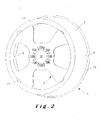
Figure 2 of the drawings appended hereto illustrates an underside, elevated perspective view of an embodiment of a plastic bottom chime according to the present invention. -
Figure 3 of the drawings is a cross-sectional view taken through the bottom chime according to the present invention, in combination, (i.e. in mounted relation) on a beer keg of the present invention. -
Figure 4 of the drawings is a more detailed view of the cross-section depicted inFigure 3 . -
Figure 5 depicts a schematic cross-sections through a stretch blow mold according to one aspect of the present invention. -
Figure 6 is an elevated cross sectional view of a chime and keg assembly according to the present invention. -
Figure 7 of the drawings appended hereto depicts a top-down elevated perspective view into a alternative embodiment of a plastic bottom chime according to the present invention. -
Figure 8 of the drawings appended hereto illustrates an underside, elevated perspective view of the embodiment of a plastic bottom chime represented infigure 7 . - Referring in general to
Figures 1 and2 of the appended drawings, there is provided a preferredkeg bottom chime 1 according to the present invention.Keg bottom chime 1 comprises a kegbottom finish surround 10.Surround 10 is specifically adapted to engage a cooperating keg bottom finish (not shown inFigures 1 and2 , but refer instead toFigures 3 and 4 ). That engagement sustains a mutually inter-fitting secured relation to thereby at least partially secure the chime to the keg. - The
chime 1 according to the present invention, comprises asurround 10 comprising an opening 10a, which is circumscribed by respective free ends 10d of a plurality of resilient,flexible tines 10b. Tines 10b extend radially inwardly into opening 10a, from fixed ends of saidtines 10b that are rooted on a inner, preferablycentral hub 3. -
Chime 1 includes a "spider" 2 for engaging a bottom portion of a keg body (again, not shown inFigures 1 and2 , refer toFigures 3 and 4 and the description that follows below), in cradled relation in thechime 1. Thespider 2 in turn comprises thecentral hub 3 with a plurality of radially outwardly extending legs or spokes 4. These spokes terminate at arim wall 5, withrim wall 5 defining one side of achannel 6 that is further bounded at the bottom thereof by achime base 13, and surrounded on a spaced apart side by anwall surface 7a of anupstanding chime skirt 7. -
Spokes contours 14, (e.g. are scallop-shaped) to provide a stiffened girder effect. - The
upstanding chime skirt 7 supports aperipheral bead 12 adapted to engage adjacent peripheral sidewall surfaces of a secured keg body. - Skirt 7 also includes
keg body drains 9 for draining liquids accumulating between theskirt 7 and an associated keg body peripheral sidewall. When in use, keg assemblies according to the present invention can accumulate water or other liquids that would remain trapped between the chime and the keg when the assembly is oriented in its normal upright position, but which is permitted to drain away through thesedrains 9. - Similarly,
bottom channel bottom 6 includeschannel drains 11 for draining liquids accumulating withchannel 6. Notably, keg assemblies according to the present invention are often washed and filled in an inverted orientation, during which time water might otherwise accumulate in the channel unless permitted to drain away through these drains. Note that the keg of the present invention and assemblies comprising same are preferably closed-system kegs. - Referring now
Figures 3 and 4 in particular, there is shown a cut away section of lower portions ofkeg body 15.Body 15 comprises aperipheral sidewall 17 and abase 15a. Thebase 15a having a kegbody bottom finish 16, which is adapted to engage a complementary kegbottom finish surround 10 ofkeg bottom chime 1 illustrated inFigures 1 and2 . -
Bottom finish 16 includes taperedside walls 16a extending proud of the periphery of thekeg body 15 and terminating in an overhangingabutment 16b that is particularly suited to engage in inter-fitting secured relation with the complementary features ofbottom chime 1 as described elsewhere herein. - It is apparent that the
bottom finish 16 forms an attachment means that can cooperate with the fixation means (kegbottom finish surround 10 withtines 10b) of the chime, and that according to the present invention, the fixation of the chime to the keg is situated at a distance of the kegs periphery. - Referring now to
Figure 5 of the drawings, there is shown an example of a blow mold useful in variously forming keg bodies for use in the present invention, from blow molded thermoplastics material. Both of the exemplary molds for producing their respective keg bodies, comprise respective means for forming the keg bottom finishes that are described elsewhere herein. - More particularly
Figure 5 illustrates a stretch blow molding mold and comprises a stretch rod adapted to extend internally of a sump defining region in the base of surround blow mold cavity. The stretch rod and the blow mold cavity co-operate to form a keg having a bottom finish (seefinish 16 inFigures 3 and 4 , for example) which includes tapered side walls (seeFigures 3 and 4 , ref.16a) extending proud of the periphery of said keg body, and terminating in an overhanging abutment 1 (seeFigures 3 and 4 and reference numeral 16b, by way of example) that is adapted to engage in said inter-fitting secured relation withbottom chime 1. - Under the preferred practice, the invention relates to the use of blow molding processes. The family of blow molding processes are employed in the production of hollow-bodied thermoplastic articles including, in particular, containers such as bottles. The basic process entails the production of pre-shaping the thermoplastic material into an intermediate for that is referred to as a parison or perform. The heated perform is then further shaped by inflating it under gas pressure, within the constraints of a mold cavity that is designed to provide the final shape of the article.
- Blow molding technology in the industrial sense, dates from the late 1930s - but its widespread commercial application was triggered in the 1950's with the introduction of high density polyethylene and the availability of non-proprietary production equipment. Since then, a variety of other thermoplastic materials (in particular with the growth of polyesters as compared with the polyolefin's - which have in some cases been associated with "flavor scalping" and concomitant swelling and increase in oxygen permeability in some beverage packaging applications) have come into use, and while high density polyethylene HDPE continues to account for as much as 55% of all blow-molded thermoplastic material, polyethylene terephthalate (PET) accounts for nearly 88% of the balance. Markets for the more expensive but, in some performance respects, superior polyethylene naphthalate (PEN) are also quickly developing, especially in returnable reusable applications.
- The family of blow-mold processes includes "extrusion", "injection" (and its relative "displacement") and "stretch", (a.k.a. "biaxial-orientation") blow molding, as well as a number of hybrids thereof.
- Extrusion blow molding is currently the most widely used of these techniques and it consists of extruding, (either intermittently or continuously), a hollow parison in a downward dropping direction. When the parison has grown sufficiently, a predetermined length thereof is embraced within a mold cavity, (e.g. by closing off two complementary mold halves around the predetermined length of the descending parison). Reciprocating screw and dual screw extrusion machines equipped with a secondary accumulator and ram for intermittent parison extrusion, are employed for small container production. For large containers, up to and including drums, however, an accumulator-head extruder with a plunger feed is employed.
- Once the parison P, see
Figure 5 , is engaged within the mold M, it is inflated under gas pressure and conforms to the rigid internal surfaces of the enclosing cavity mold, taking on a hollow-bodied shape that will ultimately lead to that of the finished container, which can include the formation of thekeg bottom finish 16. Note that while older blow molding machines required an additional reaming action to bring container finishes to final specifications (and presented problems with debris being left behind within the resulting bottle), this problem has been overcome for smaller containers through the cooperative interaction of the glow pin and the mold neck ring while the blown bottle is still resident in the mold. However, wide-mouth blow molded containers still must be finished in a subsequent trim press operation. - Injection blow molding is a multi-stage operation (historically a two step, but now almost universally a three step operation) in which the parison is injection molded into a space defined by a parison mold and a core rod disposed therein, (instead of being extruded), and is then transferred (e.g. on the core rod) into a subsequent blow-molding station. In a "displacement" variant of this type of blow molding, a measured quantity of thermoplastic melt is inserted in a parison mold, and the core rod is then inserted into the mold to forcibly displace the melt into the spaces remaining between the core rod and the molds inner surfaces - thus forming the parison.
- Stretch blow molding is particularly suited to applications involving thermoplastics capable of taking up internal linear molecular orientations - such as PET. The parison can be either extrusion molded or injection molded, although the latter is most often used in association with stretch blow molding operations. What specifically characterizes the stretch blow mold process is that the preformed parison is carefully conditioned to just above the thermoplastic's glass transition temperature (i.e. where it is warm enough to permit the parison to be inflated but cool enough to retard post-alignment re-randomization of the molecular structure), and then stretched, oriented, ("partial" and axially or bi-axially) and blown. The strain-induced crystallization in the stretched thermoplastic can, in the case of PET be increased by as much as 20, and even to as high as 28%.
- A core rod R is employed as shown in
figure 5 . Note that in a particularly preferred practice of the present invention, and in addition to providing for a component of the axial stretching of parison P during the blowing operation, rod R can also be extended to force plastic material into a portion BF of the mold cavity M, to produce exterior kegbottom finish 16. Portion BF includes means for clampingfinish 16 to produce a waist at 16a, which then broadens out at 16b. - Finally, there is provided a keg and chime assembly as illustrated in
Figure 6 . In that connection, reference is made toFigures 1 through 4 and6 . The assembly compriseskeg body 15 having abase 15a bearing a kegbody bottom finish 16.Keg bottom chime 1 comprises a kegbottom finish surround 10. The kegbottom finish surround 10 and thekeg bottom finish 16 are mutually adapted to engage a cooperating keg bottom finish in inter-fitting secured relation to thereby at least partially secure said chime and keg in mutually assembled relation. In the variously illustrated embodiments, the inter-fitting secured relation is a resiliently biased mechanically interfering registration between the salient portions ofkeg 15 and saidchime 1. As illustrated inFigure 6 , thebottom chime 1 is depicted at rest, in stacked relation on a cooperative surface T of a supporting keg, not shown, but substantially identical to the top chime C illustrated in surmounted relation on the top ofkeg 15. - It is clear that in order to fix a
chime 1 according to the invention to a keg, it suffices to position thechime 1 with theopening 10a over thekeg bottom finish 16 and to press it down such that the flexible tines snap behind the overhangingabutment 16b. - In the case the keg is a plastic keg, it is preferred to provide an internal overpressure in the keg in order to avoid any deformation thereof during fixation of the
chime 1. - For removal of the
chime 1, one can tear of thechime 1, although the removal can easily be automated by use of a cylindrical drill, breaking thetines 10b, whereby thechime 1 will fall of the keg as are thetines 10b. Such automated and simple removal of the chime obviously simplifies recycling the keg assemblies. - It is noted that when kegs of different dimensions but with standardized bottom finishes, the assembly of the
chime 1 and keg can be automated independent of the keg dimensions. Such automation is particularly useful for recycling as no sorting of the kegs is necessary. -
Figures 7 and8 represent an alternative embodiment of thechime 1 according the invention. In this embodiment, the chime comprises four concentrically cylindrical walls 17-18-19-20, theoutermost wall 17 defining the skirt of thechime 1. - The
outermost wall 17 and the wall adjacent thereto are mutually connected at one of their edges by atransversal rim 21, while theinnermost wall 20 and thewall 19 adjacent thereto are mutually connected with anothertransversal rim 22. Both rims 21 and 22 are preferably situated in a same imaginary plane and define a base of thechime 1. This base is preferably provided withzones 23 of increased roughness to increase grip of the base when positioned on ground. - The free edge of the
outermost wall 17 is provided with aperipheral bead 12 and drains 9 corresponding to that described with respect to the chime represented infigures 1 to 4 . - The free edges of both
intermediate walls annular rim 24, while the free edge of theinnermost wall 20 extends in acentral hub 3 corresponding to that described with respect to the chime represented infigures 1 to 4 and surrounding the keg bottomfinish finish surround 10. - As will be appreciated from the drawings, drains 25 are provided at the transition of the
walls 17 to 20 and the correspondingrims innermost wall 20 and thecentral hub 3. - The application of this alternative chime on a keg is identical to that described with respect to the chime represented in
figures 1 to 4 . - Finally it is remarked that both the keg and the chime can have various forms. The kegs for example can have a circular cross section, a rectangular cross section or a cross section in any other shape.
Claims (5)
- Keg assembly comprising a keg and a chime (1) fixed to each other, wherein(a) the keg has a first end comprising an opening and a second end (15a) defining a base separated from the first end by a peripheral side wall (17), said second end (15a) comprising attachment means (16) situated at a distance from said peripheral side wall (17),(b) the chime (1) comprises a substantially central inner hub (3) and fixation means (10) fixed to said attachment means (16) of the keg,
characterized in that,(c) said chime fixation means (10) comprise an opening (10a) circumscribed by respective free ends of a plurality of resilient tines (10b) extending radially inwardly from the inner hub, and in that,(d) said attachment means (16) comprise tapered side walls (16a) extending transversally from the second end (15a) and terminating in an overhanging abutment (16b) and are engaged in snap-fitting secured relationship with the complementary features of the bottom chime - Keg assembly according to claim 1, characterized in that the fixation between the keg and chime is a releasable fixation
- Keg assembly according to any of the preceding claims, characterized in that the keg is manufactured in a thermoplastic material.
- Chime suitable for being fixed to the bottom end of a keg, said chime comprising:• a substantially central inner hub (3) with fixation means (10) suitable for fixing the chime to the base end of said keg, said central inner hub (3) being surrounded by,• a rim wall of a skirt (7) whereby the skirt is suitable for engaging the peripheral side wall (17) of said keg,characterized in that, said chime fixation means (10) comprise an opening (10a) circumscribed by respective free ends of a plurality of resilient tines (10b) extending radially inwardly from the inner hub.
- Chime according to claim 4, comprising a plurality of legs (4) extending radially outwardly from the substantially central inner hub (3) and terminating in said rim wall of a skirt (7).
Applications Claiming Priority (3)
| Application Number | Priority Date | Filing Date | Title |
|---|---|---|---|
| GB0702672A GB2446393A (en) | 2007-02-12 | 2007-02-12 | A Plastic Lower Chime and Keg Assembly for Beverage Kegs |
| GB0724455A GB0724455D0 (en) | 2007-12-14 | 2007-12-14 | Container and chime method of manufacturing said container |
| PCT/EP2008/051685 WO2008098935A1 (en) | 2007-02-12 | 2008-02-12 | Container and chime and method of manufacturing said container |
Publications (2)
| Publication Number | Publication Date |
|---|---|
| EP2114780A1 EP2114780A1 (en) | 2009-11-11 |
| EP2114780B1 true EP2114780B1 (en) | 2013-04-03 |
Family
ID=39362639
Family Applications (1)
| Application Number | Title | Priority Date | Filing Date |
|---|---|---|---|
| EP08716814A Not-in-force EP2114780B1 (en) | 2007-02-12 | 2008-02-12 | Keg assembly and chime for being fixed to the bottom of a keg |
Country Status (5)
| Country | Link |
|---|---|
| US (1) | US20100320214A1 (en) |
| EP (1) | EP2114780B1 (en) |
| BR (1) | BRPI0808076A2 (en) |
| RU (1) | RU2470843C2 (en) |
| WO (1) | WO2008098935A1 (en) |
Families Citing this family (8)
| Publication number | Priority date | Publication date | Assignee | Title |
|---|---|---|---|---|
| RU2494936C2 (en) * | 2007-02-12 | 2013-10-10 | Инбев С.А. | Container, chime and their assembling |
| BE1019191A3 (en) * | 2010-02-19 | 2012-04-03 | Gysen August | STACKABLE BOTTLE WITH HANDLE. |
| GB2481436A (en) * | 2010-06-24 | 2011-12-28 | Silvia Romana Marabini | Chime attachment means and tamper evident cap |
| GB2490966B (en) * | 2011-05-20 | 2013-12-11 | Petainer Lidkoping Ab | Keg support system |
| EP2690028A1 (en) | 2012-07-27 | 2014-01-29 | Eurokeg B.V. | Container for liquids |
| MA42363A (en) | 2014-04-11 | 2018-05-16 | Dak Americas Llc | IMPROVING THE FALLING IMPACT OF AN EBM EPET CONTAINER |
| GB2552712A (en) * | 2016-08-05 | 2018-02-07 | Pet Eng & Services S R L | Containers with adhesively attached chimes |
| GB2560024B (en) * | 2017-02-27 | 2020-04-22 | Petainer Large Container Ip Ltd | Keg chime |
Family Cites Families (20)
| Publication number | Priority date | Publication date | Assignee | Title |
|---|---|---|---|---|
| FR775196A (en) | 1934-06-30 | 1934-12-21 | Rubber or similar shock absorber for containers and articles of all kinds | |
| US2905351A (en) * | 1956-02-27 | 1959-09-22 | Braun Co W | Snap-on base for a bottle, jar, glass, or the like |
| US2918188A (en) * | 1957-03-07 | 1959-12-22 | Jeannette Glass Company | Container construction |
| US3726429A (en) * | 1970-12-28 | 1973-04-10 | Monsanto Co | Package for holding pressurized fluent materials |
| NL7305209A (en) * | 1972-04-17 | 1973-10-19 | ||
| US4088239A (en) * | 1977-05-23 | 1978-05-09 | Owens-Illinois, Inc. | Plastic drum and metal handling ring |
| FI57239C (en) * | 1977-06-10 | 1980-07-10 | Hackman Ab Oy | FLYTTBAR DISTRIBUTIONSBEHAOLLARE FOER VAETSKOR POWDER EL DYL |
| JPS603071Y2 (en) * | 1981-03-05 | 1985-01-28 | サッポロビール株式会社 | Synthetic resin bottle |
| DE3336681C1 (en) | 1983-10-08 | 1984-12-20 | Hoesch Ag, 4600 Dortmund | Top or bottom ring on drums |
| US4573604A (en) * | 1985-07-15 | 1986-03-04 | Guim R | Tilt free container |
| US4955492A (en) | 1989-05-17 | 1990-09-11 | Hoover Universal, Inc. | Plastic bottle with reinforcing ring encircling the bottle base |
| DE3925165A1 (en) * | 1989-07-28 | 1991-02-07 | Ultrakust Electronic Gmbh | SAMPLE CONTAINER |
| JPH1035679A (en) | 1996-07-19 | 1998-02-10 | Yoshida Kogyo Kk <Ykk> | Container with dissimilar materials |
| US5813643A (en) * | 1997-09-11 | 1998-09-29 | Zybert; Mark | Cylinder holder for cylindrical tank |
| DE29816750U1 (en) * | 1998-09-18 | 1998-12-17 | Schäfer Werke GmbH, 57290 Neunkirchen | container |
| US6827994B2 (en) * | 2001-12-13 | 2004-12-07 | Avi Ellman | Portable weighted gripping device |
| US20040034918A1 (en) | 2002-03-14 | 2004-02-26 | Casey Loyd | Adjustable water therapy combination |
| CA2444708A1 (en) * | 2002-10-16 | 2004-04-16 | Richard D. Bushey | Self adjusting furniture glide |
| US20040134918A1 (en) * | 2003-01-10 | 2004-07-15 | Lynn Irwin | Multi-piece vessel |
| JP4739725B2 (en) * | 2004-10-22 | 2011-08-03 | 日精エー・エス・ビー機械株式会社 | Pressure vessel and molding method thereof |
-
2008
- 2008-02-12 RU RU2009134112/12A patent/RU2470843C2/en not_active IP Right Cessation
- 2008-02-12 WO PCT/EP2008/051685 patent/WO2008098935A1/en not_active Ceased
- 2008-02-12 BR BRPI0808076-3A patent/BRPI0808076A2/en not_active IP Right Cessation
- 2008-02-12 EP EP08716814A patent/EP2114780B1/en not_active Not-in-force
- 2008-02-12 US US12/449,488 patent/US20100320214A1/en not_active Abandoned
Also Published As
| Publication number | Publication date |
|---|---|
| RU2470843C2 (en) | 2012-12-27 |
| WO2008098935A1 (en) | 2008-08-21 |
| US20100320214A1 (en) | 2010-12-23 |
| BRPI0808076A2 (en) | 2014-07-22 |
| EP2114780A1 (en) | 2009-11-11 |
| RU2009134112A (en) | 2011-03-20 |
Similar Documents
| Publication | Publication Date | Title |
|---|---|---|
| US20100320214A1 (en) | Container and chime and method of manufacturing said container | |
| US20230234746A1 (en) | Container system and method of manufacture | |
| EP0277557B1 (en) | Blow molded plastic container | |
| CA2428727C (en) | Bottle base | |
| US8550272B2 (en) | Extrusion blow molded pet container having superior column strength | |
| US9758271B2 (en) | Container having a bottom provided with a vault with a double indentation | |
| EP3375593B1 (en) | Method for forming a container with a plastic liner and fibre-based shell by blow molding, preform and container | |
| EP2240370B1 (en) | Hybrid base design | |
| US4187276A (en) | Method of making a plastic package | |
| WO2021146097A1 (en) | Tubular container | |
| US9586713B2 (en) | Preform for producing plastic containers in a stretch-blow-moulding process | |
| EP3375592B1 (en) | Container | |
| US20130186848A1 (en) | Method for producing blow-molded containers and blow-molded container | |
| MX2013013142A (en) | PLASTICSâMATERIAL CONTAINER WHICH IS PRODUCED BY STRETCH BLOW MOULDING AND HAS A CUT NECK. | |
| EP0907483A4 (en) | BLOW-MOLDED PLASTIC CONTAINER AND MANUFACTURING METHOD THEREOF | |
| CN101610954B (en) | Container and chime structure and method and mold for manufacturing said container | |
| CA3201346A1 (en) | Container base with deep inset recesses | |
| CA3222571A1 (en) | Container base with straps and diaphragm | |
| WO2012073744A1 (en) | Preform | |
| JP5593076B2 (en) | Resin container and molding method of resin container | |
| JP2005112440A (en) | Container | |
| US20260097880A1 (en) | Container system and method of manufacture | |
| CN216735222U (en) | High-strength blow-molded bottle blank | |
| WO2008059256A2 (en) | Method and apparatus for making a container with a pressure accomodating base | |
| CA1130521A (en) | Plastic package |
Legal Events
| Date | Code | Title | Description |
|---|---|---|---|
| PUAI | Public reference made under article 153(3) epc to a published international application that has entered the european phase |
Free format text: ORIGINAL CODE: 0009012 |
|
| 17P | Request for examination filed |
Effective date: 20090817 |
|
| AK | Designated contracting states |
Kind code of ref document: A1 Designated state(s): AT BE BG CH CY CZ DE DK EE ES FI FR GB GR HR HU IE IS IT LI LT LU LV MC MT NL NO PL PT RO SE SI SK TR |
|
| DAX | Request for extension of the european patent (deleted) | ||
| 17Q | First examination report despatched |
Effective date: 20100503 |
|
| GRAP | Despatch of communication of intention to grant a patent |
Free format text: ORIGINAL CODE: EPIDOSNIGR1 |
|
| RAP1 | Party data changed (applicant data changed or rights of an application transferred) |
Owner name: ANHEUSER-BUSCH INBEV S.A. |
|
| GRAS | Grant fee paid |
Free format text: ORIGINAL CODE: EPIDOSNIGR3 |
|
| GRAA | (expected) grant |
Free format text: ORIGINAL CODE: 0009210 |
|
| AK | Designated contracting states |
Kind code of ref document: B1 Designated state(s): AT BE BG CH CY CZ DE DK EE ES FI FR GB GR HR HU IE IS IT LI LT LU LV MC MT NL NO PL PT RO SE SI SK TR |
|
| REG | Reference to a national code |
Ref country code: GB Ref legal event code: FG4D |
|
| REG | Reference to a national code |
Ref country code: AT Ref legal event code: REF Ref document number: 604562 Country of ref document: AT Kind code of ref document: T Effective date: 20130415 Ref country code: CH Ref legal event code: EP |
|
| REG | Reference to a national code |
Ref country code: IE Ref legal event code: FG4D |
|
| REG | Reference to a national code |
Ref country code: DE Ref legal event code: R096 Ref document number: 602008023443 Country of ref document: DE Effective date: 20130529 |
|
| REG | Reference to a national code |
Ref country code: NL Ref legal event code: T3 |
|
| REG | Reference to a national code |
Ref country code: AT Ref legal event code: MK05 Ref document number: 604562 Country of ref document: AT Kind code of ref document: T Effective date: 20130403 |
|
| PG25 | Lapsed in a contracting state [announced via postgrant information from national office to epo] |
Ref country code: SI Free format text: LAPSE BECAUSE OF FAILURE TO SUBMIT A TRANSLATION OF THE DESCRIPTION OR TO PAY THE FEE WITHIN THE PRESCRIBED TIME-LIMIT Effective date: 20130403 |
|
| REG | Reference to a national code |
Ref country code: LT Ref legal event code: MG4D |
|
| PG25 | Lapsed in a contracting state [announced via postgrant information from national office to epo] |
Ref country code: IS Free format text: LAPSE BECAUSE OF FAILURE TO SUBMIT A TRANSLATION OF THE DESCRIPTION OR TO PAY THE FEE WITHIN THE PRESCRIBED TIME-LIMIT Effective date: 20130803 Ref country code: GR Free format text: LAPSE BECAUSE OF FAILURE TO SUBMIT A TRANSLATION OF THE DESCRIPTION OR TO PAY THE FEE WITHIN THE PRESCRIBED TIME-LIMIT Effective date: 20130704 Ref country code: AT Free format text: LAPSE BECAUSE OF FAILURE TO SUBMIT A TRANSLATION OF THE DESCRIPTION OR TO PAY THE FEE WITHIN THE PRESCRIBED TIME-LIMIT Effective date: 20130403 Ref country code: FI Free format text: LAPSE BECAUSE OF FAILURE TO SUBMIT A TRANSLATION OF THE DESCRIPTION OR TO PAY THE FEE WITHIN THE PRESCRIBED TIME-LIMIT Effective date: 20130403 Ref country code: SE Free format text: LAPSE BECAUSE OF FAILURE TO SUBMIT A TRANSLATION OF THE DESCRIPTION OR TO PAY THE FEE WITHIN THE PRESCRIBED TIME-LIMIT Effective date: 20130403 Ref country code: LT Free format text: LAPSE BECAUSE OF FAILURE TO SUBMIT A TRANSLATION OF THE DESCRIPTION OR TO PAY THE FEE WITHIN THE PRESCRIBED TIME-LIMIT Effective date: 20130403 Ref country code: ES Free format text: LAPSE BECAUSE OF FAILURE TO SUBMIT A TRANSLATION OF THE DESCRIPTION OR TO PAY THE FEE WITHIN THE PRESCRIBED TIME-LIMIT Effective date: 20130714 Ref country code: PT Free format text: LAPSE BECAUSE OF FAILURE TO SUBMIT A TRANSLATION OF THE DESCRIPTION OR TO PAY THE FEE WITHIN THE PRESCRIBED TIME-LIMIT Effective date: 20130805 Ref country code: NO Free format text: LAPSE BECAUSE OF FAILURE TO SUBMIT A TRANSLATION OF THE DESCRIPTION OR TO PAY THE FEE WITHIN THE PRESCRIBED TIME-LIMIT Effective date: 20130703 |
|
| PG25 | Lapsed in a contracting state [announced via postgrant information from national office to epo] |
Ref country code: HR Free format text: LAPSE BECAUSE OF FAILURE TO SUBMIT A TRANSLATION OF THE DESCRIPTION OR TO PAY THE FEE WITHIN THE PRESCRIBED TIME-LIMIT Effective date: 20130403 Ref country code: LV Free format text: LAPSE BECAUSE OF FAILURE TO SUBMIT A TRANSLATION OF THE DESCRIPTION OR TO PAY THE FEE WITHIN THE PRESCRIBED TIME-LIMIT Effective date: 20130403 Ref country code: PL Free format text: LAPSE BECAUSE OF FAILURE TO SUBMIT A TRANSLATION OF THE DESCRIPTION OR TO PAY THE FEE WITHIN THE PRESCRIBED TIME-LIMIT Effective date: 20130403 Ref country code: BG Free format text: LAPSE BECAUSE OF FAILURE TO SUBMIT A TRANSLATION OF THE DESCRIPTION OR TO PAY THE FEE WITHIN THE PRESCRIBED TIME-LIMIT Effective date: 20130703 Ref country code: CY Free format text: LAPSE BECAUSE OF FAILURE TO SUBMIT A TRANSLATION OF THE DESCRIPTION OR TO PAY THE FEE WITHIN THE PRESCRIBED TIME-LIMIT Effective date: 20130403 |
|
| PG25 | Lapsed in a contracting state [announced via postgrant information from national office to epo] |
Ref country code: SK Free format text: LAPSE BECAUSE OF FAILURE TO SUBMIT A TRANSLATION OF THE DESCRIPTION OR TO PAY THE FEE WITHIN THE PRESCRIBED TIME-LIMIT Effective date: 20130403 Ref country code: DK Free format text: LAPSE BECAUSE OF FAILURE TO SUBMIT A TRANSLATION OF THE DESCRIPTION OR TO PAY THE FEE WITHIN THE PRESCRIBED TIME-LIMIT Effective date: 20130403 Ref country code: EE Free format text: LAPSE BECAUSE OF FAILURE TO SUBMIT A TRANSLATION OF THE DESCRIPTION OR TO PAY THE FEE WITHIN THE PRESCRIBED TIME-LIMIT Effective date: 20130403 |
|
| PLBE | No opposition filed within time limit |
Free format text: ORIGINAL CODE: 0009261 |
|
| STAA | Information on the status of an ep patent application or granted ep patent |
Free format text: STATUS: NO OPPOSITION FILED WITHIN TIME LIMIT |
|
| PG25 | Lapsed in a contracting state [announced via postgrant information from national office to epo] |
Ref country code: IT Free format text: LAPSE BECAUSE OF FAILURE TO SUBMIT A TRANSLATION OF THE DESCRIPTION OR TO PAY THE FEE WITHIN THE PRESCRIBED TIME-LIMIT Effective date: 20130403 Ref country code: RO Free format text: LAPSE BECAUSE OF FAILURE TO SUBMIT A TRANSLATION OF THE DESCRIPTION OR TO PAY THE FEE WITHIN THE PRESCRIBED TIME-LIMIT Effective date: 20130403 |
|
| 26N | No opposition filed |
Effective date: 20140106 |
|
| REG | Reference to a national code |
Ref country code: DE Ref legal event code: R097 Ref document number: 602008023443 Country of ref document: DE Effective date: 20140106 |
|
| PG25 | Lapsed in a contracting state [announced via postgrant information from national office to epo] |
Ref country code: MC Free format text: LAPSE BECAUSE OF FAILURE TO SUBMIT A TRANSLATION OF THE DESCRIPTION OR TO PAY THE FEE WITHIN THE PRESCRIBED TIME-LIMIT Effective date: 20130403 Ref country code: LU Free format text: LAPSE BECAUSE OF FAILURE TO SUBMIT A TRANSLATION OF THE DESCRIPTION OR TO PAY THE FEE WITHIN THE PRESCRIBED TIME-LIMIT Effective date: 20140212 |
|
| REG | Reference to a national code |
Ref country code: CH Ref legal event code: PL |
|
| PG25 | Lapsed in a contracting state [announced via postgrant information from national office to epo] |
Ref country code: CH Free format text: LAPSE BECAUSE OF NON-PAYMENT OF DUE FEES Effective date: 20140228 Ref country code: LI Free format text: LAPSE BECAUSE OF NON-PAYMENT OF DUE FEES Effective date: 20140228 |
|
| REG | Reference to a national code |
Ref country code: IE Ref legal event code: MM4A |
|
| PG25 | Lapsed in a contracting state [announced via postgrant information from national office to epo] |
Ref country code: IE Free format text: LAPSE BECAUSE OF NON-PAYMENT OF DUE FEES Effective date: 20140212 |
|
| REG | Reference to a national code |
Ref country code: FR Ref legal event code: PLFP Year of fee payment: 9 |
|
| PG25 | Lapsed in a contracting state [announced via postgrant information from national office to epo] |
Ref country code: MT Free format text: LAPSE BECAUSE OF FAILURE TO SUBMIT A TRANSLATION OF THE DESCRIPTION OR TO PAY THE FEE WITHIN THE PRESCRIBED TIME-LIMIT Effective date: 20130403 |
|
| PG25 | Lapsed in a contracting state [announced via postgrant information from national office to epo] |
Ref country code: TR Free format text: LAPSE BECAUSE OF FAILURE TO SUBMIT A TRANSLATION OF THE DESCRIPTION OR TO PAY THE FEE WITHIN THE PRESCRIBED TIME-LIMIT Effective date: 20130403 Ref country code: HU Free format text: LAPSE BECAUSE OF FAILURE TO SUBMIT A TRANSLATION OF THE DESCRIPTION OR TO PAY THE FEE WITHIN THE PRESCRIBED TIME-LIMIT; INVALID AB INITIO Effective date: 20080212 |
|
| REG | Reference to a national code |
Ref country code: FR Ref legal event code: PLFP Year of fee payment: 10 |
|
| REG | Reference to a national code |
Ref country code: FR Ref legal event code: PLFP Year of fee payment: 11 |
|
| PGFP | Annual fee paid to national office [announced via postgrant information from national office to epo] |
Ref country code: NL Payment date: 20190218 Year of fee payment: 12 |
|
| PGFP | Annual fee paid to national office [announced via postgrant information from national office to epo] |
Ref country code: DE Payment date: 20190219 Year of fee payment: 12 Ref country code: CZ Payment date: 20190207 Year of fee payment: 12 Ref country code: GB Payment date: 20190218 Year of fee payment: 12 |
|
| PGFP | Annual fee paid to national office [announced via postgrant information from national office to epo] |
Ref country code: FR Payment date: 20190220 Year of fee payment: 12 Ref country code: BE Payment date: 20190218 Year of fee payment: 12 |
|
| REG | Reference to a national code |
Ref country code: DE Ref legal event code: R119 Ref document number: 602008023443 Country of ref document: DE |
|
| REG | Reference to a national code |
Ref country code: NL Ref legal event code: MM Effective date: 20200301 |
|
| GBPC | Gb: european patent ceased through non-payment of renewal fee |
Effective date: 20200212 |
|
| REG | Reference to a national code |
Ref country code: BE Ref legal event code: MM Effective date: 20200229 |
|
| PG25 | Lapsed in a contracting state [announced via postgrant information from national office to epo] |
Ref country code: CZ Free format text: LAPSE BECAUSE OF NON-PAYMENT OF DUE FEES Effective date: 20200212 |
|
| PG25 | Lapsed in a contracting state [announced via postgrant information from national office to epo] |
Ref country code: NL Free format text: LAPSE BECAUSE OF NON-PAYMENT OF DUE FEES Effective date: 20200301 |
|
| PG25 | Lapsed in a contracting state [announced via postgrant information from national office to epo] |
Ref country code: GB Free format text: LAPSE BECAUSE OF NON-PAYMENT OF DUE FEES Effective date: 20200212 Ref country code: FR Free format text: LAPSE BECAUSE OF NON-PAYMENT OF DUE FEES Effective date: 20200229 Ref country code: DE Free format text: LAPSE BECAUSE OF NON-PAYMENT OF DUE FEES Effective date: 20200901 |
|
| PG25 | Lapsed in a contracting state [announced via postgrant information from national office to epo] |
Ref country code: BE Free format text: LAPSE BECAUSE OF NON-PAYMENT OF DUE FEES Effective date: 20200229 |