WO2012073744A1 - Preform - Google Patents
Preform Download PDFInfo
- Publication number
- WO2012073744A1 WO2012073744A1 PCT/JP2011/076828 JP2011076828W WO2012073744A1 WO 2012073744 A1 WO2012073744 A1 WO 2012073744A1 JP 2011076828 W JP2011076828 W JP 2011076828W WO 2012073744 A1 WO2012073744 A1 WO 2012073744A1
- Authority
- WO
- WIPO (PCT)
- Prior art keywords
- preform
- lightening
- main body
- peripheral surface
- outer peripheral
- Prior art date
Links
Images


Classifications
-
- B—PERFORMING OPERATIONS; TRANSPORTING
- B29—WORKING OF PLASTICS; WORKING OF SUBSTANCES IN A PLASTIC STATE IN GENERAL
- B29B—PREPARATION OR PRETREATMENT OF THE MATERIAL TO BE SHAPED; MAKING GRANULES OR PREFORMS; RECOVERY OF PLASTICS OR OTHER CONSTITUENTS OF WASTE MATERIAL CONTAINING PLASTICS
- B29B11/00—Making preforms
- B29B11/14—Making preforms characterised by structure or composition
-
- B—PERFORMING OPERATIONS; TRANSPORTING
- B29—WORKING OF PLASTICS; WORKING OF SUBSTANCES IN A PLASTIC STATE IN GENERAL
- B29C—SHAPING OR JOINING OF PLASTICS; SHAPING OF MATERIAL IN A PLASTIC STATE, NOT OTHERWISE PROVIDED FOR; AFTER-TREATMENT OF THE SHAPED PRODUCTS, e.g. REPAIRING
- B29C49/00—Blow-moulding, i.e. blowing a preform or parison to a desired shape within a mould; Apparatus therefor
- B29C49/071—Preforms or parisons characterised by their configuration, e.g. geometry, dimensions or physical properties
-
- B—PERFORMING OPERATIONS; TRANSPORTING
- B29—WORKING OF PLASTICS; WORKING OF SUBSTANCES IN A PLASTIC STATE IN GENERAL
- B29C—SHAPING OR JOINING OF PLASTICS; SHAPING OF MATERIAL IN A PLASTIC STATE, NOT OTHERWISE PROVIDED FOR; AFTER-TREATMENT OF THE SHAPED PRODUCTS, e.g. REPAIRING
- B29C2949/00—Indexing scheme relating to blow-moulding
- B29C2949/07—Preforms or parisons characterised by their configuration
- B29C2949/0715—Preforms or parisons characterised by their configuration the preform having one end closed
-
- B—PERFORMING OPERATIONS; TRANSPORTING
- B29—WORKING OF PLASTICS; WORKING OF SUBSTANCES IN A PLASTIC STATE IN GENERAL
- B29C—SHAPING OR JOINING OF PLASTICS; SHAPING OF MATERIAL IN A PLASTIC STATE, NOT OTHERWISE PROVIDED FOR; AFTER-TREATMENT OF THE SHAPED PRODUCTS, e.g. REPAIRING
- B29C2949/00—Indexing scheme relating to blow-moulding
- B29C2949/07—Preforms or parisons characterised by their configuration
- B29C2949/072—Preforms or parisons characterised by their configuration having variable wall thickness
-
- B—PERFORMING OPERATIONS; TRANSPORTING
- B29—WORKING OF PLASTICS; WORKING OF SUBSTANCES IN A PLASTIC STATE IN GENERAL
- B29C—SHAPING OR JOINING OF PLASTICS; SHAPING OF MATERIAL IN A PLASTIC STATE, NOT OTHERWISE PROVIDED FOR; AFTER-TREATMENT OF THE SHAPED PRODUCTS, e.g. REPAIRING
- B29C2949/00—Indexing scheme relating to blow-moulding
- B29C2949/07—Preforms or parisons characterised by their configuration
- B29C2949/073—Preforms or parisons characterised by their configuration having variable diameter
-
- B—PERFORMING OPERATIONS; TRANSPORTING
- B29—WORKING OF PLASTICS; WORKING OF SUBSTANCES IN A PLASTIC STATE IN GENERAL
- B29C—SHAPING OR JOINING OF PLASTICS; SHAPING OF MATERIAL IN A PLASTIC STATE, NOT OTHERWISE PROVIDED FOR; AFTER-TREATMENT OF THE SHAPED PRODUCTS, e.g. REPAIRING
- B29C2949/00—Indexing scheme relating to blow-moulding
- B29C2949/07—Preforms or parisons characterised by their configuration
- B29C2949/076—Preforms or parisons characterised by their configuration characterised by the shape
- B29C2949/0768—Preforms or parisons characterised by their configuration characterised by the shape characterised by the shape of specific parts of preform
- B29C2949/0769—Preforms or parisons characterised by their configuration characterised by the shape characterised by the shape of specific parts of preform characterised by the lip, i.e. very top of preform neck
-
- B—PERFORMING OPERATIONS; TRANSPORTING
- B29—WORKING OF PLASTICS; WORKING OF SUBSTANCES IN A PLASTIC STATE IN GENERAL
- B29C—SHAPING OR JOINING OF PLASTICS; SHAPING OF MATERIAL IN A PLASTIC STATE, NOT OTHERWISE PROVIDED FOR; AFTER-TREATMENT OF THE SHAPED PRODUCTS, e.g. REPAIRING
- B29C2949/00—Indexing scheme relating to blow-moulding
- B29C2949/07—Preforms or parisons characterised by their configuration
- B29C2949/076—Preforms or parisons characterised by their configuration characterised by the shape
- B29C2949/0768—Preforms or parisons characterised by their configuration characterised by the shape characterised by the shape of specific parts of preform
- B29C2949/077—Preforms or parisons characterised by their configuration characterised by the shape characterised by the shape of specific parts of preform characterised by the neck
- B29C2949/0772—Closure retaining means
- B29C2949/0773—Threads
-
- B—PERFORMING OPERATIONS; TRANSPORTING
- B29—WORKING OF PLASTICS; WORKING OF SUBSTANCES IN A PLASTIC STATE IN GENERAL
- B29C—SHAPING OR JOINING OF PLASTICS; SHAPING OF MATERIAL IN A PLASTIC STATE, NOT OTHERWISE PROVIDED FOR; AFTER-TREATMENT OF THE SHAPED PRODUCTS, e.g. REPAIRING
- B29C2949/00—Indexing scheme relating to blow-moulding
- B29C2949/07—Preforms or parisons characterised by their configuration
- B29C2949/076—Preforms or parisons characterised by their configuration characterised by the shape
- B29C2949/0768—Preforms or parisons characterised by their configuration characterised by the shape characterised by the shape of specific parts of preform
- B29C2949/077—Preforms or parisons characterised by their configuration characterised by the shape characterised by the shape of specific parts of preform characterised by the neck
- B29C2949/0777—Tamper-evident band retaining ring
-
- B—PERFORMING OPERATIONS; TRANSPORTING
- B29—WORKING OF PLASTICS; WORKING OF SUBSTANCES IN A PLASTIC STATE IN GENERAL
- B29C—SHAPING OR JOINING OF PLASTICS; SHAPING OF MATERIAL IN A PLASTIC STATE, NOT OTHERWISE PROVIDED FOR; AFTER-TREATMENT OF THE SHAPED PRODUCTS, e.g. REPAIRING
- B29C2949/00—Indexing scheme relating to blow-moulding
- B29C2949/07—Preforms or parisons characterised by their configuration
- B29C2949/076—Preforms or parisons characterised by their configuration characterised by the shape
- B29C2949/0768—Preforms or parisons characterised by their configuration characterised by the shape characterised by the shape of specific parts of preform
- B29C2949/0779—Preforms or parisons characterised by their configuration characterised by the shape characterised by the shape of specific parts of preform characterised by the body
-
- B—PERFORMING OPERATIONS; TRANSPORTING
- B29—WORKING OF PLASTICS; WORKING OF SUBSTANCES IN A PLASTIC STATE IN GENERAL
- B29C—SHAPING OR JOINING OF PLASTICS; SHAPING OF MATERIAL IN A PLASTIC STATE, NOT OTHERWISE PROVIDED FOR; AFTER-TREATMENT OF THE SHAPED PRODUCTS, e.g. REPAIRING
- B29C2949/00—Indexing scheme relating to blow-moulding
- B29C2949/20—Preforms or parisons whereby a specific part is made of only one component, e.g. only one layer
- B29C2949/22—Preforms or parisons whereby a specific part is made of only one component, e.g. only one layer at neck portion
-
- B—PERFORMING OPERATIONS; TRANSPORTING
- B29—WORKING OF PLASTICS; WORKING OF SUBSTANCES IN A PLASTIC STATE IN GENERAL
- B29C—SHAPING OR JOINING OF PLASTICS; SHAPING OF MATERIAL IN A PLASTIC STATE, NOT OTHERWISE PROVIDED FOR; AFTER-TREATMENT OF THE SHAPED PRODUCTS, e.g. REPAIRING
- B29C2949/00—Indexing scheme relating to blow-moulding
- B29C2949/20—Preforms or parisons whereby a specific part is made of only one component, e.g. only one layer
- B29C2949/24—Preforms or parisons whereby a specific part is made of only one component, e.g. only one layer at flange portion
-
- B—PERFORMING OPERATIONS; TRANSPORTING
- B29—WORKING OF PLASTICS; WORKING OF SUBSTANCES IN A PLASTIC STATE IN GENERAL
- B29C—SHAPING OR JOINING OF PLASTICS; SHAPING OF MATERIAL IN A PLASTIC STATE, NOT OTHERWISE PROVIDED FOR; AFTER-TREATMENT OF THE SHAPED PRODUCTS, e.g. REPAIRING
- B29C2949/00—Indexing scheme relating to blow-moulding
- B29C2949/20—Preforms or parisons whereby a specific part is made of only one component, e.g. only one layer
- B29C2949/26—Preforms or parisons whereby a specific part is made of only one component, e.g. only one layer at body portion
-
- B—PERFORMING OPERATIONS; TRANSPORTING
- B29—WORKING OF PLASTICS; WORKING OF SUBSTANCES IN A PLASTIC STATE IN GENERAL
- B29C—SHAPING OR JOINING OF PLASTICS; SHAPING OF MATERIAL IN A PLASTIC STATE, NOT OTHERWISE PROVIDED FOR; AFTER-TREATMENT OF THE SHAPED PRODUCTS, e.g. REPAIRING
- B29C2949/00—Indexing scheme relating to blow-moulding
- B29C2949/20—Preforms or parisons whereby a specific part is made of only one component, e.g. only one layer
- B29C2949/28—Preforms or parisons whereby a specific part is made of only one component, e.g. only one layer at bottom portion
-
- B—PERFORMING OPERATIONS; TRANSPORTING
- B29—WORKING OF PLASTICS; WORKING OF SUBSTANCES IN A PLASTIC STATE IN GENERAL
- B29C—SHAPING OR JOINING OF PLASTICS; SHAPING OF MATERIAL IN A PLASTIC STATE, NOT OTHERWISE PROVIDED FOR; AFTER-TREATMENT OF THE SHAPED PRODUCTS, e.g. REPAIRING
- B29C2949/00—Indexing scheme relating to blow-moulding
- B29C2949/30—Preforms or parisons made of several components
- B29C2949/3024—Preforms or parisons made of several components characterised by the number of components or by the manufacturing technique
Definitions
- the present invention relates to a preform formed into a plastic bottle by biaxial stretch blow molding.
- plastic bottles mainly composed of polyethylene terephthalate resin are manufactured by biaxially stretching blow-molding a preform.
- plastic bottles mainly composed of polyethylene terephthalate resin are manufactured by biaxially stretching blow-molding a preform.
- the applicant of the present invention has proposed a bead ring and a support ring as a structure for reducing the weight of the bottle mouth (same as the mouth of the preform) without sacrificing the strength of the mouth.
- Patent Document 1 The structure described in Patent Document 1 is useful in that the amount of preform resin can be reduced by the amount of meat removal. However, further reduction of the amount of resin is desired from the viewpoint of resource saving in recent years.
- an object of the present invention is to provide a preform that can further reduce the amount of resin.
- the inventor of the present invention focused on the biaxial stretch blow molding method as a result of intensive studies on how to reduce the amount of resin while taking into consideration the strength, moldability, and container handling appropriateness.
- this molding method generally, a bottomed cylindrical preform main body continuous to the lower end of the support ring of the mouth is stretched without stretching the mouth of the preform.
- the present inventor has found that the lower part of the support ring (that is, the boundary part with the mouth part in the preform main body part) remains thick without being stretched in the same manner as the bottle body part.
- the present invention has been completed.
- the preform of the present invention is composed of a mouth portion and a bottomed cylindrical preform body portion extending from the mouth portion, and the preform body portion without being stretched by biaxial stretch blow molding.
- the preform body is evenly distributed in the circumferential direction of the preform at the boundary with the mouth and stretched by biaxial stretch blow molding. It has a plurality of lightening portions formed at intervals.
- the boundary portion that has remained thick in the conventional portion of the preform main body is cut out, the amount of resin in the cut out portion can be reduced. Further, compared with the case where the entire boundary portion is uniformly thinned, the strength of the boundary portion does not need to be greatly reduced. In particular, since the lightening portions are formed at equal intervals, the strength of the boundary portion is well balanced in the circumferential direction, and the amount of resin is reduced in consideration of strength. Moreover, in the case of forming a preform by an injection molding method, the fluidity of the injected resin is better than the case where a thin portion is provided in the entire circumferential direction in order to form the thinned portions at equal intervals. Thus, molding defects are less likely to occur.
- the mouth portion may have a circumferential ring portion having a diameter larger than that of the preform main body portion at a portion defining a boundary with the preform main body portion.
- the preform main body portion has a cylindrical outer peripheral surface having no unevenness that is continuous with the lower end of the circumferential ring portion, and is formed on the outer peripheral surface continuous with the lower end of the cylindrical outer peripheral surface without the unevenness. It is good to form the extraction part.
- the preform and thus the plastic bottle after molding can be stably handled by using the peripheral ring portion and the cylindrical outer peripheral surface without unevenness. Thereby, the handleability at the time of handling a preform and a plastic bottle can be improved.
- the height of the thinned portion is larger than the height of the cylindrical outer peripheral surface having no irregularities.
- the portion of the lightening portion is closer to the circumferential ring portion, and the amount of lightening is larger, and the amount of lightening gradually decreases as the distance from the circumferential ring portion increases, and finally disappears. Good.
- the formability from the preform to the plastic bottle is improved. Specifically, the portion of the lightening portion farthest from the circumferential ring portion is easily stretched, but if there is a step at this portion, the preform may burst during biaxial stretch blow molding. . Therefore, according to the preferable aspect in which such a step is eliminated, the moldability to the plastic bottle can be ensured. Moreover, since the part of the lightening part close
- the mouth portion may have a second circumferential ring portion on the upper side of the circumferential ring portion and a thread on the upper side of the second circumferential ring. Further, when a plurality of lightening portions are formed on the outer peripheral surface between the circumferential ring portion and the second circumferential ring portion at the same equal interval as the plurality of lightening portions in the preform main body portion. Good.
- the amount of resin can be further reduced as a whole preform.
- both the hollowed portions of the mouth portion and the preform main body portion are equally spaced from each other, the strength of the upper and lower portions of the circumferential ring portion not only improves the balance in the circumferential direction, but also an injection molding method.
- the preform is molded by the above-described method, the fluidity of the resin and the removal of the mold are improved, and molding defects are less likely to occur.
- the cross-sectional shape of the thinned portion is an arc shape.
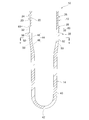
- FIG. 3 is a longitudinal sectional view of the preform cut along the line III-III in FIG. 2, which is cut at a position that does not pass through a preformed portion of the preform.
- FIG. 4 is a longitudinal sectional view of a preform cut at an angle different from that of FIG. 3, and is cut at a position passing through a preformed portion and a central axis.
- FIG. 5 is a cross-sectional view taken along line VV in FIG. 3.
- the direction where the mouth portion exists is the upper side
- the direction where the preform main body portion exists is the lower side.
- the height means a length along the direction (vertical direction) of the central axis of the preform.
- the cross-sectional shape means a cross-sectional shape in a plane (transverse section) orthogonal to the central axis.
- the plastic bottle 1 has a mouth part 2, a shoulder part 3, a trunk part 4, and a bottom part 5 in order from the upper side. These parts (2, 3, 4 and 5) are integrally formed and constitute a bottle wall for storing a beverage therein.
- the beverage include non-carbonated beverages such as water, green tea, oolong tea, and fruit juice.
- the liquid filled in the plastic bottle 1 may be a food such as a carbonated drink or a sauce.
- the preform 10 includes a mouth portion 12 and a bottomed tubular preform body portion 14 extending downward from the mouth portion 12.
- the preform 10 is manufactured by injection molding using polyethylene terephthalate as a main material, and is then formed into a plastic bottle 1 by being subjected to biaxial stretch blow molding. At this time, only the preform main body portion 14 is stretched by the biaxial stretch blow molding, and the mouth portion 12 is not stretched. For this reason, the shape and size of the mouth portion 2 of the plastic bottle 1 are the same as the shape and size of the mouth portion 12 of the preform 10.
- a thermoplastic resin other than polyethylene terephthalate for example, polyethylene or polypropylene
- the mouth portion 12 has a cylindrical peripheral wall 20 having an upper end opened.
- the inner peripheral surface 22 of the peripheral wall 20 extends in the vertical direction without a step, while the outer peripheral surface 24 of the peripheral wall 20 is formed with a screw thread 26, a bead ring 28, and a support ring 30 in order from the top. Yes.
- the sealing performance of the plastic bottle 1 is maintained by fitting a cap (not shown) to the mouth portion 2 using the screw thread 26.
- Each of the bead ring 28 and the support ring 30 is a circumferential ring portion (sometimes referred to as a flange portion) having a larger diameter than the preform main body portion 14, and extends outwardly from the outer peripheral surface 24 in the circumferential direction. Protruding.
- a plurality of lightening portions 32 are formed on the outer peripheral surface of the outer peripheral surface 24 between the bead ring 28 and the support ring 30.
- a boundary between the mouth portion 12 and the preform main body portion 14 is defined by the support ring 30, and the upper portion (that is, the entire mouth portion 12) from the lower surface of the support ring 30 is not stretched in the biaxial stretch blow molding.
- the preform main body 14 has a cylindrical body 40 having a constant diameter, a bottom 42 continuous to the lower part of the body 40, and a support continuously to the upper part of the body 40. And a neck portion 44 continuous with the lower end of the ring 30.
- the bottom portion 42 is often hemispherical, but is not limited to such a shape, and may be any shape that closes the lower portion of the body portion 40.
- the neck portion 44 has a curved portion 46 extending upward from the upper portion of the body portion 40 so as to expand slightly and a short cylindrical shape extending from the curved portion 46 to the support ring 30 without being curved.
- a vertical portion 48 Further, on the outer peripheral surface of the neck portion 44, a plurality of lightening portions 50 are formed at equal intervals in the circumferential direction.
- the thickness of the trunk portion 40 and the bottom portion 42 is the same or substantially the same, but the thickness of the vertical portion 48 is It is slightly smaller than the thickness of the body 40 and the bottom 42. For this reason, the thickness of the bending portion 46 is configured to gradually decrease from the trunk portion 40 to the vertical portion 48. Further, the thickness of the vertical portion 48 is the same as or substantially the same as the thickness of the portion between the bead ring 28 and the support ring 30, and the thickness of the portion where the screw thread 26 exists (the upper portion of the mouth portion 12). Bigger than.
- the preform main body portion 14 has the largest outer diameter of the vertical portion 48, and the outer diameter is the same or substantially the same as the outer diameter of the portion between the bead ring 28 and the support ring 30. It is.
- the thinned portion 50 As shown in FIG. 5, there are a total of eight thinned portions 50, which are lined up symmetrically with equal intervals in the circumferential direction across the column portion 52.
- a portion 54 that connects the lightening portion 50 and the column portion 52 is rounded by an arc having a center of curvature inside the preform main body portion 14 so that both are smoothly connected.
- the cross-sectional shape of the lightening portion 50 is an arc shape curved inward of the preform main body portion 14. Therefore, the thinned portion 50 has the thinnest central portion and is gradually thickened at both ends thereof.
- the difference between the minimum outer diameter of the lightening portion 50 and the outer diameter of the column portion 52 is preferably 3.0 mm or less, more preferably 1.5 mm to 2.0 mm. This is because if the thickness exceeds 3.0 mm, the thermoplastic resin may not reach both ends of the thinned portion 50 when the preform 10 is injection-molded.
- the arcuate R (curvature radius) of the thinned portion 50 is preferably in the range of 5 to 50 mm, more preferably 30 mm. When R is less than 5 mm, undercutting occurs, and it becomes difficult to take out the preform 10 from the mold. On the other hand, when R exceeds 50 mm, it is not possible to sufficiently obtain a lightening effect for weight reduction.
- an outer peripheral surface 56 without unevenness is formed between the thinned portion 50 and the support ring 30.
- the outer peripheral surface 56 is a short cylindrical surface continuous with the lower edge of the base end side of the support ring 30 and is different from the outer peripheral surface where the thinned portion 50 and the column portion 52 exist in that the thinned portion 50 is not thinned. Yes.
- the outer peripheral surface 56 is flush with the outer peripheral surface constituting the column part 52.
- the height of the outer peripheral surface 56 is sufficiently shorter than the height of the thinned portion 50, the length is not limited as long as it can be stably gripped when the preform 10 is handled. If a preferable example is given, the height of the outer peripheral surface 56 is 1 mm or more and 2 mm or less.
- the thinned portion 50 is mainly formed on the outer peripheral surface of the vertical portion 48, and a part thereof also reaches the outer peripheral surface of the curved portion 46.
- the depth of the lightening portion 50 (that is, the amount of lightening) can be constant over the height direction, or can be made smaller in the curved portion 46 than in the vertical portion 48 as shown in FIG. it can.
- the thickness of the lightening portion 50 gradually decreases as it goes downward. More preferably, the amount of lightening of the lightening portion 50 is larger as the portion is closer to the support ring 30, gradually decreases as the distance from the support ring 30 increases, and continues to the outer peripheral surface of the body portion 40 without a step. Eventually disappear.
- the lightening portion 32 on the mouth portion 12 side can be formed in the same manner as the lightening portion 50 on the preform main body portion 14 side.
- the total number of the lightening portions 32 is eight, and the columnar portions 60 are spaced apart from each other and arranged in a line-symmetric manner at equal intervals in the circumferential direction, so that the cross-sectional shape can be an arc shape.
- the preform main body portion 14 when the preform main body portion 14 is stretched, the lightening portion 50 and the column portion 52 are stretched until there is no boundary between them (that is, a step), and constitute the upper portion of the shoulder portion 3. .
- the thinned portion 50 existing in the preform 10 disappears. Therefore, if it sees as the plastic bottle 1, it will become unclear whether the preform 10 for the manufacture has used the one having the lightening portion 50.
- the thinned portion 50 is partially formed in the lower portion of the support ring 30 that has not been stretched and remains thick.
- the amount of resin (amount of polyethylene terephthalate) used for the preform 10 can be reduced.
- a strength fall can be suppressed.
- the thinned portions 50 are formed at equal intervals, the strength of the lower portion of the support ring 30 is well balanced in the circumferential direction, and the amount of resin is reduced in consideration of strength.
- the thinned portions 50 are formed at equal intervals, so that the injected resin flows in a well-balanced manner. Moreover, since the thinned portion 50 is formed in an arc-shaped cross section, it is easy to ensure the fluidity of the resin. Furthermore, since the thinned portion 50 has such an aspect, after injection molding, the product (preform 10) can be easily extracted from the mold used for injection molding, and molding defects are unlikely to occur. Therefore, the moldability of the preform 10 can be maintained well, and the productivity of the plastic bottle 1 can be improved.
- the structure of the preform 10 described above can be modified as appropriate without departing from the scope of the present invention.
- the number of the lightening portions 50 is not limited to eight and may be two or more. It is also possible to form the thinned portion 50 not on the outer peripheral surface of the neck portion 44 but on the inner peripheral surface of the neck portion 44. However, from the viewpoint of ease of die removal of the mold, it is preferable to form it on the outer peripheral surface.
Abstract
Provided is a preform in which the amount of resin can be further reduced. A preform (10) is constituted by a mouth portion (12), and a bottomed cylindrical preform main body (14) extending from the mouth portion (12), wherein the preform main body (14) is stretched by biaxial stretching blow molding, while the mouth portion (12) is not stretched, to form a plastic bottle. The preform main body (14) comprises a plurality of volume-reducing portions (50) formed at a uniform interval in the circumferential direction of the preform (10), at a boundary portion to the mouth portion (12) and a portion to be stretched by the biaxial stretching blow molding.
Description
本発明は、二軸延伸ブロー成形されることでプラスチックボトルへと成形されるプリフォームに関するものである。
The present invention relates to a preform formed into a plastic bottle by biaxial stretch blow molding.
一般に、ポリエチレンテレフタレート樹脂を主体とするプラスチックボトル(ペットボトル)は、プリフォームを二軸延伸ブロー成形することで製造される。近年では、プリフォームの樹脂量を削減した軽量化ボトルを製造することが強く要請されるようになってきている。
Generally, plastic bottles (pet bottles) mainly composed of polyethylene terephthalate resin are manufactured by biaxially stretching blow-molding a preform. In recent years, there has been a strong demand for manufacturing lightweight bottles with a reduced amount of preform resin.
このような要請に鑑み、本出願人は、ボトルの口部(プリフォームの口部と同じ。)について、口部の強度を犠牲にすることなく軽量化する構造として、ビードリングとサポートリングとの間の外周面を部分的に肉抜きする構造を提案している(特許文献1参照。)。
In view of such a request, the applicant of the present invention has proposed a bead ring and a support ring as a structure for reducing the weight of the bottle mouth (same as the mouth of the preform) without sacrificing the strength of the mouth. Has proposed a structure in which the outer peripheral surface is partially thinned (see Patent Document 1).
特許文献1に記載の構造は、肉抜きした分だけ、プリフォームの樹脂量を減らすことができる点で有用である。しかしながら、近年の資源節約の観点では、樹脂量のさらなる削減が望まれている。
The structure described in Patent Document 1 is useful in that the amount of preform resin can be reduced by the amount of meat removal. However, further reduction of the amount of resin is desired from the viewpoint of resource saving in recent years.
そこで、本発明は、樹脂量をより一層削減することができるプリフォームを提供することをその目的としている。
Therefore, an object of the present invention is to provide a preform that can further reduce the amount of resin.
本発明者は、強度面、成形性、容器のハンドリング適正に配慮しながら樹脂量を減らすにはどうすればよいか、鋭意検討を重ねた結果、二軸延伸ブロー成形法に着目した。この成形法では、一般に、プリフォームの口部を延伸せずに、口部のサポートリングの下端に連続した有底筒状のプリフォーム本体部を延伸していく。本発明者は、サポートリングの下部(すなわち、プリフォーム本体部における口部との境界部分)が、ボトル胴部と同じようには延伸されずに厚肉のまま残っていることを見出し、以下の本発明を完成するに至った。
The inventor of the present invention focused on the biaxial stretch blow molding method as a result of intensive studies on how to reduce the amount of resin while taking into consideration the strength, moldability, and container handling appropriateness. In this molding method, generally, a bottomed cylindrical preform main body continuous to the lower end of the support ring of the mouth is stretched without stretching the mouth of the preform. The present inventor has found that the lower part of the support ring (that is, the boundary part with the mouth part in the preform main body part) remains thick without being stretched in the same manner as the bottle body part. The present invention has been completed.
すなわち、本発明のプリフォームは、口部と口部から延在する有底筒状のプリフォーム本体部とから構成され、二軸延伸ブロー成形によって口部が延伸されることなくプリフォーム本体部が延伸されてプラスチックボトルへと成形されるプリフォームにおいて、プリフォーム本体部が、口部との境界部分であって且つ二軸延伸ブロー成形によって延伸される部分に、プリフォームの周方向に均等の間隔で形成された複数の肉抜き部を有しているものである。
That is, the preform of the present invention is composed of a mouth portion and a bottomed cylindrical preform body portion extending from the mouth portion, and the preform body portion without being stretched by biaxial stretch blow molding. In a preform that is stretched and molded into a plastic bottle, the preform body is evenly distributed in the circumferential direction of the preform at the boundary with the mouth and stretched by biaxial stretch blow molding. It has a plurality of lightening portions formed at intervals.
本発明によれば、プリフォーム本体部の部位のうち、従来厚肉のまま残っていた境界部分を肉抜きしているので、肉抜き分の樹脂量を削減することができる。また、境界部分の全体を均一に薄肉にする場合に比べて、境界部分の強度を大きく低下させずに済む。特に、肉抜き部を均等間隔で形成しているため、境界部分の強度が周方向においてバランスが良くなり、強度面に配慮した樹脂量の削減となる。しかも、射出成形法によりプリフォームを成形する場合にあっては、均等間隔で肉抜き部を形成するため、周方向全体に薄肉部を設ける場合と比較し、射出された樹脂の流動性が良くなり、成形不良が起こり難くなる。
According to the present invention, since the boundary portion that has remained thick in the conventional portion of the preform main body is cut out, the amount of resin in the cut out portion can be reduced. Further, compared with the case where the entire boundary portion is uniformly thinned, the strength of the boundary portion does not need to be greatly reduced. In particular, since the lightening portions are formed at equal intervals, the strength of the boundary portion is well balanced in the circumferential direction, and the amount of resin is reduced in consideration of strength. Moreover, in the case of forming a preform by an injection molding method, the fluidity of the injected resin is better than the case where a thin portion is provided in the entire circumferential direction in order to form the thinned portions at equal intervals. Thus, molding defects are less likely to occur.
本発明の好ましい一態様によれば、口部は、プリフォーム本体部との境界を画定する部分に、プリフォーム本体部よりも大径の周状リング部を有しているとよい。また、プリフォーム本体部は、周状リング部の下端に連続する凹凸のない筒状の外周面を有していると共に、この凹凸のない筒状の外周面の下端に連続する外周面に肉抜き部を形成しているとよい。
According to a preferred aspect of the present invention, the mouth portion may have a circumferential ring portion having a diameter larger than that of the preform main body portion at a portion defining a boundary with the preform main body portion. In addition, the preform main body portion has a cylindrical outer peripheral surface having no unevenness that is continuous with the lower end of the circumferential ring portion, and is formed on the outer peripheral surface continuous with the lower end of the cylindrical outer peripheral surface without the unevenness. It is good to form the extraction part.
かかる態様によれば、周状リング部及び凹凸のない筒状の外周面を利用して、プリフォームひいては成形後のプラスチックボトルを安定してハンドリングすることができる。これにより、プリフォーム及びプラスチックボトルを取り扱う際のハンドリング性を向上することができる。
According to this aspect, the preform and thus the plastic bottle after molding can be stably handled by using the peripheral ring portion and the cylindrical outer peripheral surface without unevenness. Thereby, the handleability at the time of handling a preform and a plastic bottle can be improved.
より好ましくは、肉抜き部の高さは、上記の凹凸のない筒状の外周面の高さよりも大きいとよい。
More preferably, the height of the thinned portion is larger than the height of the cylindrical outer peripheral surface having no irregularities.
また、本発明の好ましい一態様によれば、肉抜き部は、周状リング部に近い部位ほど肉抜き量が大きく、周状リング部から遠ざかるにつれて肉抜き量が徐々に減り、最終的に消滅するとよい。
Further, according to a preferred aspect of the present invention, the portion of the lightening portion is closer to the circumferential ring portion, and the amount of lightening is larger, and the amount of lightening gradually decreases as the distance from the circumferential ring portion increases, and finally disappears. Good.
かかる態様によれば、プリフォームからプラスチックボトルへの成形性が向上する。具体的には、周状リング部から最も遠い肉抜き部の部位は延伸され易いが、この部位に段差があると、二軸延伸ブロー成形を行っている間にプリフォームがバーストするおそれがある。したがって、このような段差がなくなる上記好ましい態様によれば、プラスチックボトルへの成形性を確保することができる。また、周状リング部に近い肉抜き部の部位ほど、二軸延伸ブロー成形の際に延伸され難いので、肉抜き量を効果的に増やすことができる。
According to this aspect, the formability from the preform to the plastic bottle is improved. Specifically, the portion of the lightening portion farthest from the circumferential ring portion is easily stretched, but if there is a step at this portion, the preform may burst during biaxial stretch blow molding. . Therefore, according to the preferable aspect in which such a step is eliminated, the moldability to the plastic bottle can be ensured. Moreover, since the part of the lightening part close | similar to a circumferential ring part is hard to be extended | stretched in the case of biaxial stretch blow molding, the amount of lightening can be increased effectively.
さらに、本発明の好ましい一態様によれば、口部は、周状リング部の上側に第2の周状リング部を、また、第2の周状リングの上側にねじ山を有するとよい。また、周状リング部と第2の周状リング部との間の外周面には、プリフォーム本体部における複数の肉抜き部と同じ均等の間隔で複数の肉抜き部が形成されているとよい。
Furthermore, according to a preferred aspect of the present invention, the mouth portion may have a second circumferential ring portion on the upper side of the circumferential ring portion and a thread on the upper side of the second circumferential ring. Further, when a plurality of lightening portions are formed on the outer peripheral surface between the circumferential ring portion and the second circumferential ring portion at the same equal interval as the plurality of lightening portions in the preform main body portion. Good.
かかる態様によれば、プリフォーム全体として樹脂量の削減をより一層図ることができる。加えて、口部及びプリフォーム本体部における両者の肉抜き部を互いに同じ均等間隔としているので、周状リング部の上下の部分の強度が周方向においてバランスが良くなるのみならず、射出成形法によりプリフォームを成形する場合に、上述した樹脂の流動性及び金型の取外しが良好となり、成形不良が起こり難くなる。
According to this aspect, the amount of resin can be further reduced as a whole preform. In addition, since both the hollowed portions of the mouth portion and the preform main body portion are equally spaced from each other, the strength of the upper and lower portions of the circumferential ring portion not only improves the balance in the circumferential direction, but also an injection molding method. When the preform is molded by the above-described method, the fluidity of the resin and the removal of the mold are improved, and molding defects are less likely to occur.
好ましくは、肉抜き部の横断面形状は、円弧形状であるとよい。
Preferably, the cross-sectional shape of the thinned portion is an arc shape.
この構成によれば、プリフォームを射出成形した場合に、台形形状に比べて、そのための金型からの取り出しが容易となる。
According to this configuration, when the preform is injection-molded, it can be easily taken out from the mold for that purpose as compared with the trapezoidal shape.
添付図面を参照して、本発明の好適な実施形態を説明する。
以下では、まず、プラスチックボトルについて簡単に説明し、その後、プラスチックボトルへと成形されるプリフォームについて詳細に説明する。また、以下の説明では、プリフォームにおいて、口部が存在する方を上側とし、プリフォーム本体部が存在する方を下側とする。高さとは、プリフォームの中心軸の方向(上下方向)に沿った長さを意味する。横断面形状とは、中心軸に直交する平面(横断面)における断面形状を意味する。 Preferred embodiments of the present invention will be described with reference to the accompanying drawings.
In the following, first, a plastic bottle will be briefly described, and then a preform molded into the plastic bottle will be described in detail. Further, in the following description, in the preform, the direction where the mouth portion exists is the upper side, and the direction where the preform main body portion exists is the lower side. The height means a length along the direction (vertical direction) of the central axis of the preform. The cross-sectional shape means a cross-sectional shape in a plane (transverse section) orthogonal to the central axis.
図1に示すように、プラスチックボトル1は、上側から順に、口部2、肩部3、胴部4及び底部5を有する。これらの部分(2,3,4及び5)は、一体に形成され、内部に飲料を貯留するためのボトル壁を構成する。飲料としては、水、緑茶、ウーロン茶又は果汁等の非炭酸飲料を挙げることができる。ただし、他の実施態様では、プラスチックボトル1に充填される液体は、炭酸飲料又はソース等の食品でもよい。
As shown in FIG. 1, the plastic bottle 1 has a mouth part 2, a shoulder part 3, a trunk part 4, and a bottom part 5 in order from the upper side. These parts (2, 3, 4 and 5) are integrally formed and constitute a bottle wall for storing a beverage therein. Examples of the beverage include non-carbonated beverages such as water, green tea, oolong tea, and fruit juice. However, in another embodiment, the liquid filled in the plastic bottle 1 may be a food such as a carbonated drink or a sauce.
図2に示すように、プリフォーム10は、口部12と、口部12から下方に延在する有底筒状のプリフォーム本体部14と、で構成される。プリフォーム10は、ポリエチレンテレフタレートを主材料として射出成形されることで製造され、その後二軸延伸ブロー成形に供されることでプラスチックボトル1へと成形される。このとき、二軸延伸ブロー成形によって延伸されるのは、プリフォーム本体部14のみであり、口部12は延伸されない。このため、プラスチックボトル1の口部2の形状・大きさは、プリフォーム10の口部12の形状・大きさと同じとなる。なお、他の実施態様では、ポリエチレンテレフタレート以外の熱可塑性樹脂(例えば、ポリエチレン又はポリプロピレン)を主材料に用いることも可能である。
As shown in FIG. 2, the preform 10 includes a mouth portion 12 and a bottomed tubular preform body portion 14 extending downward from the mouth portion 12. The preform 10 is manufactured by injection molding using polyethylene terephthalate as a main material, and is then formed into a plastic bottle 1 by being subjected to biaxial stretch blow molding. At this time, only the preform main body portion 14 is stretched by the biaxial stretch blow molding, and the mouth portion 12 is not stretched. For this reason, the shape and size of the mouth portion 2 of the plastic bottle 1 are the same as the shape and size of the mouth portion 12 of the preform 10. In other embodiments, a thermoplastic resin other than polyethylene terephthalate (for example, polyethylene or polypropylene) can be used as the main material.
図2~4に示すように、口部12は、上端を開口した円筒状の周壁20を有する。周壁20の内周面22は、上下方向に段差なしで延在している一方、周壁20の外周面24には、上から順に、ねじ山26、ビードリング28及びサポートリング30が形成されている。プラスチックボトル1における密封性は、ねじ山26を利用して、キャップ(図示省略)を口部2に嵌合することで保たれる。ビードリング28及びサポートリング30は、いずれも、プリフォーム本体部14よりも大径の周状リング部(フランジ部と呼称される場合もある。)であり、周方向にわたって外周面24の外方に突出している。外周面24のうち、ビードリング28とサポートリング30との間の外周面には、複数の肉抜き部32が形成されている。サポートリング30によって口部12とプリフォーム本体部14との境界が画定されており、サポートリング30の下面から上側部分(すなわち、口部12全体)は二軸延伸ブロー成形において延伸されない。
2 to 4, the mouth portion 12 has a cylindrical peripheral wall 20 having an upper end opened. The inner peripheral surface 22 of the peripheral wall 20 extends in the vertical direction without a step, while the outer peripheral surface 24 of the peripheral wall 20 is formed with a screw thread 26, a bead ring 28, and a support ring 30 in order from the top. Yes. The sealing performance of the plastic bottle 1 is maintained by fitting a cap (not shown) to the mouth portion 2 using the screw thread 26. Each of the bead ring 28 and the support ring 30 is a circumferential ring portion (sometimes referred to as a flange portion) having a larger diameter than the preform main body portion 14, and extends outwardly from the outer peripheral surface 24 in the circumferential direction. Protruding. A plurality of lightening portions 32 are formed on the outer peripheral surface of the outer peripheral surface 24 between the bead ring 28 and the support ring 30. A boundary between the mouth portion 12 and the preform main body portion 14 is defined by the support ring 30, and the upper portion (that is, the entire mouth portion 12) from the lower surface of the support ring 30 is not stretched in the biaxial stretch blow molding.
図2~5に示すように、プリフォーム本体部14は、一定径からなる円筒状の胴部40と、胴部40の下部に連続する底部42と、胴部40の上部に連続してサポートリング30の下端に連続するネック部44と、で構成される。底部42は、半球状となっている場合が多いが、このような形状に限るものではなく、胴部40の下部を閉塞する形状であればよい。ネック部44は、胴部40の上部から僅かになだらかに拡開するように上方へと延在する湾曲部46と、湾曲部46からサポートリング30へと湾曲することなく延在する短円筒状の鉛直部48と、で構成される。また、ネック部44の外周面には、複数の肉抜き部50が周方向に均等間隔で形成されている。
As shown in FIGS. 2 to 5, the preform main body 14 has a cylindrical body 40 having a constant diameter, a bottom 42 continuous to the lower part of the body 40, and a support continuously to the upper part of the body 40. And a neck portion 44 continuous with the lower end of the ring 30. The bottom portion 42 is often hemispherical, but is not limited to such a shape, and may be any shape that closes the lower portion of the body portion 40. The neck portion 44 has a curved portion 46 extending upward from the upper portion of the body portion 40 so as to expand slightly and a short cylindrical shape extending from the curved portion 46 to the support ring 30 without being curved. , And a vertical portion 48. Further, on the outer peripheral surface of the neck portion 44, a plurality of lightening portions 50 are formed at equal intervals in the circumferential direction.
ここで、肉抜き部50を除いた部分の肉厚に着目すると、プリフォーム本体部14では、胴部40及び底部42の肉厚は同じ又は略同じであるが、鉛直部48の肉厚は胴部40及び底部42の肉厚よりも僅かに小さい。このため、湾曲部46の肉厚は、胴部40から鉛直部48にかけて徐々に小さくなるように構成されている。また、鉛直部48の肉厚は、ビードリング28とサポートリング30との間の部分の肉厚と同じ又は略同じであり、ねじ山26が存在する部分(口部12の上部)の肉厚よりも大きい。さらに、外径に着目すると、プリフォーム本体部14では、鉛直部48の外径が最も大きく、その外径は、ビードリング28とサポートリング30との間の部分の外径と同じ又は略同じである。
Here, focusing on the thickness of the portion excluding the thinned portion 50, in the preform main body portion 14, the thickness of the trunk portion 40 and the bottom portion 42 is the same or substantially the same, but the thickness of the vertical portion 48 is It is slightly smaller than the thickness of the body 40 and the bottom 42. For this reason, the thickness of the bending portion 46 is configured to gradually decrease from the trunk portion 40 to the vertical portion 48. Further, the thickness of the vertical portion 48 is the same as or substantially the same as the thickness of the portion between the bead ring 28 and the support ring 30, and the thickness of the portion where the screw thread 26 exists (the upper portion of the mouth portion 12). Bigger than. Further, focusing attention on the outer diameter, the preform main body portion 14 has the largest outer diameter of the vertical portion 48, and the outer diameter is the same or substantially the same as the outer diameter of the portion between the bead ring 28 and the support ring 30. It is.
図5に示すように、肉抜き部50は、全部で8個あり、それぞれ、柱部52を隔てて周方向に均等間隔で且つ線対称に並んでいる。肉抜き部50と柱部52とをつなぐ部分54は、両者がなだらかにつながるように、プリフォーム本体部14の内側に曲率中心を有する円弧によりR取りされている。肉抜き部50の横断面形状は、プリフォーム本体部14の内方向へと湾曲した円弧形状からなる。したがって、肉抜き部50は、その中央部が最も薄肉であり、その両端にかけて徐々に厚肉化されている。
As shown in FIG. 5, there are a total of eight thinned portions 50, which are lined up symmetrically with equal intervals in the circumferential direction across the column portion 52. A portion 54 that connects the lightening portion 50 and the column portion 52 is rounded by an arc having a center of curvature inside the preform main body portion 14 so that both are smoothly connected. The cross-sectional shape of the lightening portion 50 is an arc shape curved inward of the preform main body portion 14. Therefore, the thinned portion 50 has the thinnest central portion and is gradually thickened at both ends thereof.
ここで、肉抜き部50における最小外径と柱部52の外径との差は、3.0mm以下であることが好ましく、より好ましくは1.5mm~2.0mmである。3.0mmを越えると、プリフォーム10を射出成形する際に、熱可塑性樹脂が肉抜き部50の両端にまで行き渡らなくなる可能性があるからである。また、肉抜き部50の円弧形状のR(曲率半径)は、5~50mmの範囲であることが好ましく、より好ましくは30mmである。5mm未満のRとすると、アンダーカットとなり、プリフォーム10を金型から取り出し難くなる一方、50mmを越えるRとすると、軽量化のための肉抜き効果を十分に得ることができないからである。
Here, the difference between the minimum outer diameter of the lightening portion 50 and the outer diameter of the column portion 52 is preferably 3.0 mm or less, more preferably 1.5 mm to 2.0 mm. This is because if the thickness exceeds 3.0 mm, the thermoplastic resin may not reach both ends of the thinned portion 50 when the preform 10 is injection-molded. Further, the arcuate R (curvature radius) of the thinned portion 50 is preferably in the range of 5 to 50 mm, more preferably 30 mm. When R is less than 5 mm, undercutting occurs, and it becomes difficult to take out the preform 10 from the mold. On the other hand, when R exceeds 50 mm, it is not possible to sufficiently obtain a lightening effect for weight reduction.
図2~4に示すように、肉抜き部50とサポートリング30との間には、凹凸のない外周面56が形成されている。外周面56は、サポートリング30の基端側の下縁に連続した短円筒状の面であり、肉抜きされていない点で、肉抜き部50及び柱部52が存在する外周面と異なっている。外周面56は、柱部52を構成する外周面と面一で連続している。外周面56の高さは、肉抜き部50の高さよりも十分に短いが、プリフォーム10をハンドリングするときに安定して把持できる長さであれば、その長さは限定されない。好ましい一例を挙げると、外周面56の高さは、1mm以上2mm以下である。
As shown in FIGS. 2 to 4, an outer peripheral surface 56 without unevenness is formed between the thinned portion 50 and the support ring 30. The outer peripheral surface 56 is a short cylindrical surface continuous with the lower edge of the base end side of the support ring 30 and is different from the outer peripheral surface where the thinned portion 50 and the column portion 52 exist in that the thinned portion 50 is not thinned. Yes. The outer peripheral surface 56 is flush with the outer peripheral surface constituting the column part 52. Although the height of the outer peripheral surface 56 is sufficiently shorter than the height of the thinned portion 50, the length is not limited as long as it can be stably gripped when the preform 10 is handled. If a preferable example is given, the height of the outer peripheral surface 56 is 1 mm or more and 2 mm or less.
肉抜き部50は、主として鉛直部48の外周面に形成され、一部が湾曲部46の外周面にも達している。肉抜き部50の深さ(すなわち肉抜き量)は、その高さ方向に亘って一定とすることもできるし、図3に示す如く鉛直部48よりも湾曲部46の方で小さくすることもできる。ただし、好ましくは、肉抜き部50は、下方に向かうにつれて、徐々に肉抜き量が減少するとよい。また、より好ましくは、肉抜き部50の肉抜き量は、サポートリング30に近い部位ほど大きく、サポートリング30から遠ざかるにつれて徐々に減っていき、胴部40の外周面と段差無く連続するように最終的に消滅するとよい。こうすることで、二軸延伸ブロー成形を行っている間にプリフォーム10がバーストし難くなるので、プラスチックボトル1への成形性を確保することができる。
The thinned portion 50 is mainly formed on the outer peripheral surface of the vertical portion 48, and a part thereof also reaches the outer peripheral surface of the curved portion 46. The depth of the lightening portion 50 (that is, the amount of lightening) can be constant over the height direction, or can be made smaller in the curved portion 46 than in the vertical portion 48 as shown in FIG. it can. However, it is preferable that the thickness of the lightening portion 50 gradually decreases as it goes downward. More preferably, the amount of lightening of the lightening portion 50 is larger as the portion is closer to the support ring 30, gradually decreases as the distance from the support ring 30 increases, and continues to the outer peripheral surface of the body portion 40 without a step. Eventually disappear. By carrying out like this, since preform 10 becomes difficult to burst while performing biaxial stretch blow molding, the moldability to plastic bottle 1 is securable.
なお、詳述しなかったが、口部12側の肉抜き部32についても、プリフォーム本体部14側の肉抜き部50と同様に形成することができる。例えば、肉抜き部32は、全部で8個あり、それぞれ柱部60を隔てて周方向に均等間隔で且つ線対称に並ばせ、横断面形状を円弧形状とすることができる。ただし、好ましくは、周方向において、肉抜き部32の位置と肉抜き部50の位置とがサポートリング30を境にそろうように、肉抜き部50を考慮して肉抜き部32の大きさ及び隣り合う肉抜き部32,32の間隔を形成するとよい。このように形成すれば、サポートリング30の上下の部分の強度が周方向においてバランスが良くなる上、樹脂の流動性及び金型の取外しが良好となる。
Although not described in detail, the lightening portion 32 on the mouth portion 12 side can be formed in the same manner as the lightening portion 50 on the preform main body portion 14 side. For example, the total number of the lightening portions 32 is eight, and the columnar portions 60 are spaced apart from each other and arranged in a line-symmetric manner at equal intervals in the circumferential direction, so that the cross-sectional shape can be an arc shape. However, preferably, in the circumferential direction, the size and the size of the lightening portion 32 in consideration of the lightening portion 50 so that the position of the lightening portion 32 and the position of the lightening portion 50 are aligned with the support ring 30 as a boundary. It is good to form the space | interval of the adjacent lightening parts 32 and 32. FIG. If formed in this way, the strength of the upper and lower portions of the support ring 30 is balanced in the circumferential direction, and the fluidity of the resin and the removal of the mold are improved.
プラスチックボトル1の製造工程の一例を説明する。
先ず、金型を使用して、金型内にポリエチレンテレフタレートを射出し、プリフォーム10を射出成形する。射出成形後、金型を開いて、プリフォーム10を取り出し、ブロー成形機にセットする。ブロー成形機にて、プリフォーム10のうち、プリフォーム本体部14のみを加熱し、延伸ロッドによってプリフォーム本体部14を縦方向に延伸させると共に、圧縮空気を吹き込んでプリフォーム本体部14を横方向に延伸させる。これにより、肩部3、胴部4及び底部5が成形される。一方、口部12はそのままの大きさ・形状を保ったまま口部2となり、プラスチックボトル1の一連の成形が完了する。 An example of the manufacturing process of theplastic bottle 1 will be described.
First, using a mold, polyethylene terephthalate is injected into the mold, and thepreform 10 is injection-molded. After injection molding, the mold is opened, the preform 10 is taken out, and set in a blow molding machine. In the blow molding machine, only the preform main body portion 14 of the preform 10 is heated, and the preform main body portion 14 is stretched in the vertical direction by the stretching rod, and the preform main body portion 14 is laterally blown by blowing compressed air. Stretch in the direction. Thereby, the shoulder part 3, the trunk | drum 4, and the bottom part 5 are shape | molded. On the other hand, the mouth 12 becomes the mouth 2 while maintaining the size and shape as it is, and a series of molding of the plastic bottle 1 is completed.
先ず、金型を使用して、金型内にポリエチレンテレフタレートを射出し、プリフォーム10を射出成形する。射出成形後、金型を開いて、プリフォーム10を取り出し、ブロー成形機にセットする。ブロー成形機にて、プリフォーム10のうち、プリフォーム本体部14のみを加熱し、延伸ロッドによってプリフォーム本体部14を縦方向に延伸させると共に、圧縮空気を吹き込んでプリフォーム本体部14を横方向に延伸させる。これにより、肩部3、胴部4及び底部5が成形される。一方、口部12はそのままの大きさ・形状を保ったまま口部2となり、プラスチックボトル1の一連の成形が完了する。 An example of the manufacturing process of the
First, using a mold, polyethylene terephthalate is injected into the mold, and the
ここで、プリフォーム本体部14が延伸されていく際、肉抜き部50と柱部52とは、両者の境界(すなわち段差)がなくなるまで延伸され、肩部3の上部を構成することになる。このため、肩部3の上部では、プリフォーム10において存在していた肉抜き部50が消失することになる。したがって、プラスチックボトル1としてみれば、その製造のためのプリフォーム10として肉抜き部50を有するものを使用したか否かは判然としなくなる。
Here, when the preform main body portion 14 is stretched, the lightening portion 50 and the column portion 52 are stretched until there is no boundary between them (that is, a step), and constitute the upper portion of the shoulder portion 3. . For this reason, in the upper part of the shoulder portion 3, the thinned portion 50 existing in the preform 10 disappears. Therefore, if it sees as the plastic bottle 1, it will become unclear whether the preform 10 for the manufacture has used the one having the lightening portion 50.
以上説明した本実施形態のプリフォーム10の作用効果について説明する。
The operational effects of the preform 10 of the present embodiment described above will be described.
1.樹脂量の削減及び強度の観点
プリフォーム本体部14の部位のうち、従来延伸されずに厚肉のまま残っていたサポートリング30の下部に肉抜き部50を部分的に形成しているので、プリフォーム10に使用する樹脂量(ポリエチレンテレフタレートの量)を削減することができる。また、サポートリング30の下部の全体の厚みを薄くする場合に比べて、強度低下を抑制することができる。特に、肉抜き部50を均等間隔で形成しているため、サポートリング30の下部の強度が周方向においてバランスが良くなり、強度面に配慮した樹脂量の削減となる。 1. In view of the reduction in the amount of resin and the strength of the preformmain body portion 14, the thinned portion 50 is partially formed in the lower portion of the support ring 30 that has not been stretched and remains thick. The amount of resin (amount of polyethylene terephthalate) used for the preform 10 can be reduced. Moreover, compared with the case where the whole thickness of the lower part of the support ring 30 is made thin, a strength fall can be suppressed. In particular, since the thinned portions 50 are formed at equal intervals, the strength of the lower portion of the support ring 30 is well balanced in the circumferential direction, and the amount of resin is reduced in consideration of strength.
プリフォーム本体部14の部位のうち、従来延伸されずに厚肉のまま残っていたサポートリング30の下部に肉抜き部50を部分的に形成しているので、プリフォーム10に使用する樹脂量(ポリエチレンテレフタレートの量)を削減することができる。また、サポートリング30の下部の全体の厚みを薄くする場合に比べて、強度低下を抑制することができる。特に、肉抜き部50を均等間隔で形成しているため、サポートリング30の下部の強度が周方向においてバランスが良くなり、強度面に配慮した樹脂量の削減となる。 1. In view of the reduction in the amount of resin and the strength of the preform
2.プリフォームの成形性の観点
プリフォーム10を射出成形する際、肉抜き部50を均等間隔で形成するため、射出された樹脂がバランス良く流動する。また、肉抜き部50を円弧形状の横断面形状に形成するので、樹脂の流動性も確保し易い。さらに、このような態様の肉抜き部50であるので、射出成形後においては、射出成形に用いた金型から製品(プリフォーム10)が抜き易くなり、成形不良が起こり難い。したがって、プリフォーム10の成形性を良好に維持することができ、プラスチックボトル1の生産性を向上することができる。 2. From the viewpoint of moldability of the preform When thepreform 10 is injection-molded, the thinned portions 50 are formed at equal intervals, so that the injected resin flows in a well-balanced manner. Moreover, since the thinned portion 50 is formed in an arc-shaped cross section, it is easy to ensure the fluidity of the resin. Furthermore, since the thinned portion 50 has such an aspect, after injection molding, the product (preform 10) can be easily extracted from the mold used for injection molding, and molding defects are unlikely to occur. Therefore, the moldability of the preform 10 can be maintained well, and the productivity of the plastic bottle 1 can be improved.
プリフォーム10を射出成形する際、肉抜き部50を均等間隔で形成するため、射出された樹脂がバランス良く流動する。また、肉抜き部50を円弧形状の横断面形状に形成するので、樹脂の流動性も確保し易い。さらに、このような態様の肉抜き部50であるので、射出成形後においては、射出成形に用いた金型から製品(プリフォーム10)が抜き易くなり、成形不良が起こり難い。したがって、プリフォーム10の成形性を良好に維持することができ、プラスチックボトル1の生産性を向上することができる。 2. From the viewpoint of moldability of the preform When the
3.ハンドリングの観点
肉抜き部50とサポートリング30との間に凹凸のない外周面56が形成されているので、この外周面56及びサポートリング30を利用して、プリフォーム10及びプラスチックボトル1を安定してハンドリングすることができる。これにより、プリフォーム10及びプラスチックボトル1を取り扱う際のハンドリング性を適切に確保することができる。 3. From the viewpoint of handling Since an outerperipheral surface 56 having no irregularities is formed between the thinned portion 50 and the support ring 30, the preform 10 and the plastic bottle 1 are stabilized by using the outer peripheral surface 56 and the support ring 30. Can be handled. Thereby, the handleability at the time of handling the preform 10 and the plastic bottle 1 can be ensured appropriately.
肉抜き部50とサポートリング30との間に凹凸のない外周面56が形成されているので、この外周面56及びサポートリング30を利用して、プリフォーム10及びプラスチックボトル1を安定してハンドリングすることができる。これにより、プリフォーム10及びプラスチックボトル1を取り扱う際のハンドリング性を適切に確保することができる。 3. From the viewpoint of handling Since an outer
本実施形態の変形例
上記したプリフォーム10の構造は、本発明の範囲を逸脱しない限り適宜設計変更することができる。例えば、肉抜き部50の個数は8個に限るものではなく、2以上の複数であればよい。また、肉抜き部50をネック部44の外周面ではなく、ネック部44の内周面に形成することも可能である。ただし、金型の型抜きのし易さの観点からすれば、外周面に形成した方が好ましい。 Modification of the Embodiment The structure of thepreform 10 described above can be modified as appropriate without departing from the scope of the present invention. For example, the number of the lightening portions 50 is not limited to eight and may be two or more. It is also possible to form the thinned portion 50 not on the outer peripheral surface of the neck portion 44 but on the inner peripheral surface of the neck portion 44. However, from the viewpoint of ease of die removal of the mold, it is preferable to form it on the outer peripheral surface.
上記したプリフォーム10の構造は、本発明の範囲を逸脱しない限り適宜設計変更することができる。例えば、肉抜き部50の個数は8個に限るものではなく、2以上の複数であればよい。また、肉抜き部50をネック部44の外周面ではなく、ネック部44の内周面に形成することも可能である。ただし、金型の型抜きのし易さの観点からすれば、外周面に形成した方が好ましい。 Modification of the Embodiment The structure of the
1:プラスチックボトル、 10:プリフォーム、 12:口部、 14:プリフォーム本体部、 24:外周面、 26:ねじ山、 28:ビードリング(第2の周状リング部)、 30:サポートリング(周状リング部)、 32:肉抜き部、 40:胴部、 42:底部、 44:ネック部、 46:湾曲部、 48:鉛直部、 50:肉抜き部、 52:柱部
1: plastic bottle, 10: preform, 12: mouth part, 14: preform body part, 24: outer peripheral surface, 26: thread, 28: bead ring (second circumferential ring part), 30: support ring (Circumferential ring part), 32: lightening part, 40: body part, 42: bottom part, 44: neck part, 46: curved part, 48: vertical part, 50: lightening part, 52: pillar part
Claims (6)
- 口部と当該口部から延在する有底筒状のプリフォーム本体部とから構成され、二軸延伸ブロー成形によって前記口部が延伸されることなく前記プリフォーム本体部が延伸されてプラスチックボトルへと成形されるプリフォームにおいて、
前記プリフォーム本体部は、前記口部との境界部分であって且つ二軸延伸ブロー成形によって延伸される部分に、当該プリフォームの周方向に均等間隔で形成された複数の肉抜き部を有している、プリフォーム。 A plastic bottle comprising a mouth portion and a bottomed cylindrical preform body portion extending from the mouth portion, and the preform body portion is stretched without stretching the mouth portion by biaxial stretch blow molding In the preform molded into
The preform main body portion has a plurality of lightening portions formed at equal intervals in the circumferential direction of the preform at a portion which is a boundary portion with the mouth portion and is stretched by biaxial stretch blow molding. It is a preform. - 前記口部は、前記プリフォーム本体部との境界を画定する部分に、前記プリフォーム本体部よりも大径の周状リング部を有し、
前記プリフォーム本体部は、前記周状リング部の下端に連続する凹凸のない筒状の外周面を有していると共に、この凹凸のない筒状の外周面の下端に連続した外周面に前記肉抜き部を形成している、請求項1に記載のプリフォーム。 The mouth portion has a circumferential ring portion having a diameter larger than that of the preform main body portion in a portion defining a boundary with the preform main body portion,
The preform main body portion has a cylindrical outer peripheral surface without unevenness that is continuous with the lower end of the circumferential ring portion, and the outer peripheral surface that is continuous with the lower end of the cylindrical outer peripheral surface without unevenness. The preform according to claim 1, wherein a thinned portion is formed. - 前記肉抜き部の高さは、前記凹凸のない筒状の外周面の高さよりも大きい、請求項2に記載のプリフォーム。 The preform according to claim 2, wherein a height of the cutout portion is larger than a height of the cylindrical outer peripheral surface without the unevenness.
- 前記肉抜き部は、前記周状リング部に近い部位ほど肉抜き量が大きく、前記周状リング部から遠ざかるにつれて肉抜き量が徐々に減って最終的に消滅する、請求項2又は3に記載のプリフォーム。 The said lightening part has a large amount of lightening as the site | part close | similar to the said circumferential ring part, and as it distances from the said circumferential ring part, the amount of lightening reduces gradually and it finally lose | disappears. Preforms.
- 前記口部は、前記周状リング部の上側に第2の周状リング部を、また、当該第2の周状リングの上側にねじ山を有し、且つ、前記周状リング部と前記第2の周状リング部との間の外周面には、前記プリフォーム本体部における複数の肉抜き部と同じ均等間隔で複数の肉抜き部が形成されている、請求項2ないし4のいずれか一項に記載のプリフォーム。 The mouth portion has a second circumferential ring portion on the upper side of the circumferential ring portion, and has a thread on the upper side of the second circumferential ring, and the circumferential ring portion and the first The outer peripheral surface between the two circumferential ring portions is formed with a plurality of lightening portions at the same equal intervals as the plurality of lightening portions in the preform main body portion. The preform according to one item.
- 前記肉抜き部の横断面形状は、円弧形状である、請求項1ないし4のいずれか一項に記載のプリフォーム。 The preform according to any one of claims 1 to 4, wherein a cross-sectional shape of the lightening portion is an arc shape.
Applications Claiming Priority (2)
| Application Number | Priority Date | Filing Date | Title |
|---|---|---|---|
| JP2010-270311 | 2010-12-03 | ||
| JP2010270311A JP5631183B2 (en) | 2010-12-03 | 2010-12-03 | preform |
Publications (1)
| Publication Number | Publication Date |
|---|---|
| WO2012073744A1 true WO2012073744A1 (en) | 2012-06-07 |
Family
ID=46171687
Family Applications (1)
| Application Number | Title | Priority Date | Filing Date |
|---|---|---|---|
| PCT/JP2011/076828 WO2012073744A1 (en) | 2010-12-03 | 2011-11-21 | Preform |
Country Status (2)
| Country | Link |
|---|---|
| JP (1) | JP5631183B2 (en) |
| WO (1) | WO2012073744A1 (en) |
Families Citing this family (4)
| Publication number | Priority date | Publication date | Assignee | Title |
|---|---|---|---|---|
| DE102014014144A1 (en) * | 2014-09-22 | 2016-03-24 | Mahir Aktas | Method and device for producing an optimized neck contour on preforms |
| JP6665034B2 (en) * | 2016-05-25 | 2020-03-13 | サントリーホールディングス株式会社 | Resin bottles and preforms |
| JP2018079574A (en) * | 2016-11-14 | 2018-05-24 | 東洋製罐株式会社 | Preform for biaxial stretch blow molding for heat-resistant container made of synthetic resin |
| US11807412B2 (en) | 2018-06-22 | 2023-11-07 | Amcor Rigid Packaging Usa, Llc | Container preform |
Citations (6)
| Publication number | Priority date | Publication date | Assignee | Title |
|---|---|---|---|---|
| JPH01182022A (en) * | 1988-01-18 | 1989-07-19 | Yoshida Kogyo Kk <Ykk> | Manufacture of polyester resin container with cloudy patterns |
| JPH0339226A (en) * | 1989-07-07 | 1991-02-20 | Nissei Ee S B Kikai Kk | Method for stretching parison in stretching blow molding |
| JPH0491924A (en) * | 1990-08-06 | 1992-03-25 | Toppan Printing Co Ltd | Manufacture of plastic bottle |
| JP2004330458A (en) * | 2003-04-30 | 2004-11-25 | Aoki Technical Laboratory Inc | Preform and thin-walled container |
| JP2005067002A (en) * | 2003-08-22 | 2005-03-17 | Toyo Seikan Kaisha Ltd | Preform for plastic bottle container |
| JP2010095269A (en) * | 2008-10-15 | 2010-04-30 | Coca Cola Co:The | Plastic bottle |
Family Cites Families (1)
| Publication number | Priority date | Publication date | Assignee | Title |
|---|---|---|---|---|
| JPS5843308B2 (en) * | 1976-02-09 | 1983-09-26 | 株式会社吉野工業所 | Biaxially stretched container |
-
2010
- 2010-12-03 JP JP2010270311A patent/JP5631183B2/en active Active
-
2011
- 2011-11-21 WO PCT/JP2011/076828 patent/WO2012073744A1/en active Application Filing
Patent Citations (6)
| Publication number | Priority date | Publication date | Assignee | Title |
|---|---|---|---|---|
| JPH01182022A (en) * | 1988-01-18 | 1989-07-19 | Yoshida Kogyo Kk <Ykk> | Manufacture of polyester resin container with cloudy patterns |
| JPH0339226A (en) * | 1989-07-07 | 1991-02-20 | Nissei Ee S B Kikai Kk | Method for stretching parison in stretching blow molding |
| JPH0491924A (en) * | 1990-08-06 | 1992-03-25 | Toppan Printing Co Ltd | Manufacture of plastic bottle |
| JP2004330458A (en) * | 2003-04-30 | 2004-11-25 | Aoki Technical Laboratory Inc | Preform and thin-walled container |
| JP2005067002A (en) * | 2003-08-22 | 2005-03-17 | Toyo Seikan Kaisha Ltd | Preform for plastic bottle container |
| JP2010095269A (en) * | 2008-10-15 | 2010-04-30 | Coca Cola Co:The | Plastic bottle |
Also Published As
| Publication number | Publication date |
|---|---|
| JP2012116160A (en) | 2012-06-21 |
| JP5631183B2 (en) | 2014-11-26 |
Similar Documents
| Publication | Publication Date | Title |
|---|---|---|
| US8323555B2 (en) | System and method for forming a container having a grip region | |
| AU2006236674B2 (en) | Method for manufacturing blow molded containers, a base assembly for forming the containers and such a container | |
| EP2571769B1 (en) | Plastic container and blow-moulding method for making same | |
| US20180002057A1 (en) | Hot fill container having superior crush resistance | |
| CN110770134A (en) | Container with bottom base provided with notches | |
| US8550272B2 (en) | Extrusion blow molded pet container having superior column strength | |
| JP5631183B2 (en) | preform | |
| JP2013028137A (en) | Preform for plastic bottle, and plastic bottle | |
| WO2016174831A1 (en) | Synthetic resin container | |
| JP2011084315A (en) | Plastic bottle | |
| JP6602528B2 (en) | Plastic bottle | |
| JP5329170B2 (en) | Plastic bottles and preforms | |
| JP6242366B2 (en) | Plastic bottle | |
| WO2018061379A1 (en) | Synthetic resin container | |
| JP6647759B2 (en) | Blow molded bottle made of synthetic resin | |
| US20110303682A1 (en) | Heat sterilizable plastic container | |
| JP7278465B1 (en) | Plastic bottle, blow mold and method for manufacturing plastic bottle | |
| JP5882578B2 (en) | Plastic bottle | |
| JP6011917B2 (en) | Synthetic resin square container and manufacturing method thereof | |
| JP2015160650A (en) | plastic bottle | |
| JP2017206313A (en) | Plastic bottle | |
| US20200130248A1 (en) | Hot fill container having superior crush resistance | |
| JP4079131B2 (en) | Biaxial stretch blow molded container and manufacturing method thereof | |
| JP2011143953A (en) | Resin container | |
| JP2015089827A (en) | Plastic bottle |
Legal Events
| Date | Code | Title | Description |
|---|---|---|---|
| 121 | Ep: the epo has been informed by wipo that ep was designated in this application |
Ref document number: 11844924 Country of ref document: EP Kind code of ref document: A1 |
|
| NENP | Non-entry into the national phase |
Ref country code: DE |
|
| 122 | Ep: pct application non-entry in european phase |
Ref document number: 11844924 Country of ref document: EP Kind code of ref document: A1 |