EP2114545B1 - Low operating head polishing sand filter - Google Patents
Low operating head polishing sand filter Download PDFInfo
- Publication number
- EP2114545B1 EP2114545B1 EP07719901.6A EP07719901A EP2114545B1 EP 2114545 B1 EP2114545 B1 EP 2114545B1 EP 07719901 A EP07719901 A EP 07719901A EP 2114545 B1 EP2114545 B1 EP 2114545B1
- Authority
- EP
- European Patent Office
- Prior art keywords
- filter
- water
- layers
- layer
- underdrain
- Prior art date
- Legal status (The legal status is an assumption and is not a legal conclusion. Google has not performed a legal analysis and makes no representation as to the accuracy of the status listed.)
- Not-in-force
Links
- 239000004576 sand Substances 0.000 title claims description 90
- 238000005498 polishing Methods 0.000 title claims description 15
- XLYOFNOQVPJJNP-UHFFFAOYSA-N water Substances O XLYOFNOQVPJJNP-UHFFFAOYSA-N 0.000 claims description 161
- 239000010410 layer Substances 0.000 claims description 88
- 239000000463 material Substances 0.000 claims description 30
- 239000002351 wastewater Substances 0.000 claims description 28
- 238000001914 filtration Methods 0.000 claims description 24
- 238000000034 method Methods 0.000 claims description 24
- 239000002245 particle Substances 0.000 claims description 22
- 238000004140 cleaning Methods 0.000 claims description 19
- 238000004519 manufacturing process Methods 0.000 claims description 12
- 230000008569 process Effects 0.000 claims description 11
- 239000011044 quartzite Substances 0.000 claims description 10
- 238000011001 backwashing Methods 0.000 claims description 7
- 239000002344 surface layer Substances 0.000 claims description 6
- VYPSYNLAJGMNEJ-UHFFFAOYSA-N Silicium dioxide Chemical compound O=[Si]=O VYPSYNLAJGMNEJ-UHFFFAOYSA-N 0.000 description 89
- 238000002203 pretreatment Methods 0.000 description 25
- XEEYBQQBJWHFJM-UHFFFAOYSA-N Iron Chemical compound [Fe] XEEYBQQBJWHFJM-UHFFFAOYSA-N 0.000 description 16
- 238000009287 sand filtration Methods 0.000 description 16
- 238000013461 design Methods 0.000 description 15
- 239000011236 particulate material Substances 0.000 description 10
- 239000002699 waste material Substances 0.000 description 10
- 241000700605 Viruses Species 0.000 description 8
- 229910052742 iron Inorganic materials 0.000 description 8
- 244000045947 parasite Species 0.000 description 8
- 241000894006 Bacteria Species 0.000 description 7
- 239000000701 coagulant Substances 0.000 description 7
- 238000012423 maintenance Methods 0.000 description 7
- 239000000126 substance Substances 0.000 description 7
- PWHULOQIROXLJO-UHFFFAOYSA-N Manganese Chemical compound [Mn] PWHULOQIROXLJO-UHFFFAOYSA-N 0.000 description 6
- 238000005516 engineering process Methods 0.000 description 6
- 229910052748 manganese Inorganic materials 0.000 description 6
- 239000011572 manganese Substances 0.000 description 6
- 230000015572 biosynthetic process Effects 0.000 description 5
- 210000003250 oocyst Anatomy 0.000 description 5
- 208000031513 cyst Diseases 0.000 description 4
- 244000052769 pathogen Species 0.000 description 4
- 239000007787 solid Substances 0.000 description 4
- 238000007792 addition Methods 0.000 description 3
- 238000013019 agitation Methods 0.000 description 3
- 238000005352 clarification Methods 0.000 description 3
- 238000010276 construction Methods 0.000 description 3
- 238000009826 distribution Methods 0.000 description 3
- 238000011068 loading method Methods 0.000 description 3
- 230000002441 reversible effect Effects 0.000 description 3
- 238000003860 storage Methods 0.000 description 3
- 230000009471 action Effects 0.000 description 2
- 230000008901 benefit Effects 0.000 description 2
- 238000005056 compaction Methods 0.000 description 2
- 230000001143 conditioned effect Effects 0.000 description 2
- 230000009849 deactivation Effects 0.000 description 2
- 230000007423 decrease Effects 0.000 description 2
- 238000011010 flushing procedure Methods 0.000 description 2
- 230000006872 improvement Effects 0.000 description 2
- 229910052751 metal Inorganic materials 0.000 description 2
- 239000002184 metal Substances 0.000 description 2
- 150000002739 metals Chemical class 0.000 description 2
- 238000012986 modification Methods 0.000 description 2
- 230000004048 modification Effects 0.000 description 2
- 238000007790 scraping Methods 0.000 description 2
- 239000000725 suspension Substances 0.000 description 2
- ZAMOUSCENKQFHK-UHFFFAOYSA-N Chlorine atom Chemical compound [Cl] ZAMOUSCENKQFHK-UHFFFAOYSA-N 0.000 description 1
- 241000223935 Cryptosporidium Species 0.000 description 1
- 206010011732 Cyst Diseases 0.000 description 1
- KRHYYFGTRYWZRS-UHFFFAOYSA-M Fluoride anion Chemical compound [F-] KRHYYFGTRYWZRS-UHFFFAOYSA-M 0.000 description 1
- 241000224466 Giardia Species 0.000 description 1
- 229910021536 Zeolite Inorganic materials 0.000 description 1
- RHZUVFJBSILHOK-UHFFFAOYSA-N anthracen-1-ylmethanolate Chemical compound C1=CC=C2C=C3C(C[O-])=CC=CC3=CC2=C1 RHZUVFJBSILHOK-UHFFFAOYSA-N 0.000 description 1
- 239000003830 anthracite Substances 0.000 description 1
- 238000013459 approach Methods 0.000 description 1
- NYOGMBUMDPBEJK-UHFFFAOYSA-N arsanylidynemanganese Chemical compound [As]#[Mn] NYOGMBUMDPBEJK-UHFFFAOYSA-N 0.000 description 1
- 229910052785 arsenic Inorganic materials 0.000 description 1
- RQNWIZPPADIBDY-UHFFFAOYSA-N arsenic atom Chemical compound [As] RQNWIZPPADIBDY-UHFFFAOYSA-N 0.000 description 1
- QVGXLLKOCUKJST-UHFFFAOYSA-N atomic oxygen Chemical compound [O] QVGXLLKOCUKJST-UHFFFAOYSA-N 0.000 description 1
- 230000033228 biological regulation Effects 0.000 description 1
- 238000005660 chlorination reaction Methods 0.000 description 1
- 239000000460 chlorine Substances 0.000 description 1
- 229910052801 chlorine Inorganic materials 0.000 description 1
- 239000004927 clay Substances 0.000 description 1
- 230000015271 coagulation Effects 0.000 description 1
- 238000005345 coagulation Methods 0.000 description 1
- 238000011161 development Methods 0.000 description 1
- 230000003292 diminished effect Effects 0.000 description 1
- HNPSIPDUKPIQMN-UHFFFAOYSA-N dioxosilane;oxo(oxoalumanyloxy)alumane Chemical compound O=[Si]=O.O=[Al]O[Al]=O HNPSIPDUKPIQMN-UHFFFAOYSA-N 0.000 description 1
- 230000008030 elimination Effects 0.000 description 1
- 238000003379 elimination reaction Methods 0.000 description 1
- 230000003628 erosive effect Effects 0.000 description 1
- 238000011156 evaluation Methods 0.000 description 1
- 238000011049 filling Methods 0.000 description 1
- 239000002223 garnet Substances 0.000 description 1
- 239000007789 gas Substances 0.000 description 1
- 230000005484 gravity Effects 0.000 description 1
- 230000000977 initiatory effect Effects 0.000 description 1
- 150000002484 inorganic compounds Chemical class 0.000 description 1
- 229910010272 inorganic material Inorganic materials 0.000 description 1
- 238000002955 isolation Methods 0.000 description 1
- 238000013332 literature search Methods 0.000 description 1
- 230000007774 longterm Effects 0.000 description 1
- WPBNNNQJVZRUHP-UHFFFAOYSA-L manganese(2+);methyl n-[[2-(methoxycarbonylcarbamothioylamino)phenyl]carbamothioyl]carbamate;n-[2-(sulfidocarbothioylamino)ethyl]carbamodithioate Chemical compound [Mn+2].[S-]C(=S)NCCNC([S-])=S.COC(=O)NC(=S)NC1=CC=CC=C1NC(=S)NC(=O)OC WPBNNNQJVZRUHP-UHFFFAOYSA-L 0.000 description 1
- 150000002894 organic compounds Chemical class 0.000 description 1
- 239000001301 oxygen Substances 0.000 description 1
- 229910052760 oxygen Inorganic materials 0.000 description 1
- 239000011148 porous material Substances 0.000 description 1
- 235000019353 potassium silicate Nutrition 0.000 description 1
- 230000001105 regulatory effect Effects 0.000 description 1
- 238000011160 research Methods 0.000 description 1
- 238000012552 review Methods 0.000 description 1
- 238000009991 scouring Methods 0.000 description 1
- 239000000377 silicon dioxide Substances 0.000 description 1
- 238000004659 sterilization and disinfection Methods 0.000 description 1
- 230000009182 swimming Effects 0.000 description 1
- 239000010457 zeolite Substances 0.000 description 1
Images



Classifications
-
- C—CHEMISTRY; METALLURGY
- C02—TREATMENT OF WATER, WASTE WATER, SEWAGE, OR SLUDGE
- C02F—TREATMENT OF WATER, WASTE WATER, SEWAGE, OR SLUDGE
- C02F1/00—Treatment of water, waste water, or sewage
- C02F1/001—Processes for the treatment of water whereby the filtration technique is of importance
-
- C—CHEMISTRY; METALLURGY
- C02—TREATMENT OF WATER, WASTE WATER, SEWAGE, OR SLUDGE
- C02F—TREATMENT OF WATER, WASTE WATER, SEWAGE, OR SLUDGE
- C02F1/00—Treatment of water, waste water, or sewage
- C02F1/001—Processes for the treatment of water whereby the filtration technique is of importance
- C02F1/004—Processes for the treatment of water whereby the filtration technique is of importance using large scale industrial sized filters
-
- C—CHEMISTRY; METALLURGY
- C02—TREATMENT OF WATER, WASTE WATER, SEWAGE, OR SLUDGE
- C02F—TREATMENT OF WATER, WASTE WATER, SEWAGE, OR SLUDGE
- C02F2303/00—Specific treatment goals
- C02F2303/16—Regeneration of sorbents, filters
Definitions
- This invention relates to a novel low operating head polishing sand filter.
- U.S. Patent No. 6,123,858, granted 26 September 2000, David H. Manz discloses a novel intermittent slow sand filter and a method of using the intermittent filter. More particularly, this invention pertains to a novel slow sand filter which remains effective, even when intermittently operated, and which can be periodically cleaned without disturbing the action of the intermittent filter.
- the slow sand filter apparatus comprises a container having an upper portion and a lower portion; a water inlet in the upper portion of the container, the water inlet being connected to a supply of water; a filter material filling at least the lower portion of the container, the filter material having a top surface below the water inlet; a schmutzdeuke layer on the top surface of the filter material; a water outlet in the lower portion of the container below the top surface of the filter material; and a water level maintenance device in the upper portion which maintains water in the upper portion of the container at a maintenance level above the top surface of the filter material, the maintenance level being a balance between (1) a water maintenance level that is sufficiently deep that water falling from the water inlet onto the top of the water in the container does not significantly disturb the schmutzdeuke layer; and (2) a water maintenance level that is sufficiently shallow that oxygen from the air above the water level can diffuse through the water and reach the schmutzdeuke layer so that the schmutzdeuke layer is maintained in living condition even when there is no flow of water through the
- BSF Biosand Water Filter
- GB 2 388 557 is directed to a treatment system having four layers of inert particulate material such that from a top layer to a bottom layer, the coarseness of the particles decreases while the density of the particulate material increases.
- the layers form a filter or fluidisable bed supported upon a perforated base plate within a column having an inlet port connected to a pumped supply of untreated water which is allowed to flow from the first layer to the fourth layer and exit the system as treated water.
- the system includes a means for backwashing the filter.
- WO 02/36234 discloses a water treatment system suitable for the elimination of Cryptosporidium oocysts from water that includes a filter bed comprising four layers of inert particulate material such that, from the top layer to the bottom layer, the coarsness of the particle decreases while the density of the particulate material increases.
- the invention is directed to a low operating head polishing sand filter comprising (a) a plural-layer media bed comprising layers of crushed quartzite, wherein (i) the top two layers have an effective particle size of less than 0.35 mm and a uniformity coefficient of 2.05 or less; (ii) the top layer has an effective particle size of 1/2 or less than a second filtering layer; (iii) the finest (top) underdrain layer has an effective particle size at least 2 times that of the filtering layer immediately above it and a uniformity coefficient of 2 or less; and (iv) underdrain layers below the finest (top) underdrain layer are sufficiently large to prevent intermixing of the layers; whereby filtered material collects on a surface layer; (b) an untreated water inlet system; (c) an underdrain system; (d) a filtered water collection and outlet system; and (e) a backwash water inlet, collection and siphon outlet system, said backwash water inlet being controllable to introduce backwash water into the filter to break up
- Rapid sand and pressure sand water filters are commonly used as polishing filters in water treatment plants. Rapid sand filters have been used for over one hundred years. Rapid and pressure sand filters are typically used as part of conventional municipal water treatment systems in which pre-treatment is provided by adding coagulants to the water, thereby allowing the formation of coagulant flocs which capture the very small particles (including parasite cysts and oocysts) and some dissolved organic and inorganic compounds.
- the water containing the flocs is then sent to clarifiers or settling basins where they settle out of the water.
- the 'clarified water' is then sent to rapid sand (which are relatively simple to control) or to pressure sand filters (which are more complex to control) for final polishing prior to disinfection.
- Rapid sand filters are gravity operated sand filters; that is, the surface of the untreated water is not pressurized to provide the force necessary to cause the water to move through the filter.
- the required filtering force is provided by a depth of water over the filter media during operation, often one meter or more.
- Rapid sand filters resembles a swimming pool. Rapid sand filters normally have deep multi-layer and multi-material media beds, most of which interface with a very extensive and often massive underdrain system that also serves as the entry and distribution for very large volumes of treated water used in the backwash process. Rapid sand filters tend to be very large in structure.
- Pressure sand filters are wholly contained in a closed vessel specially designed to withstand the forces resulting from operation under pressure. Pressure sand filters are very compact when compared to rapid sand filters. Similar to a rapid sand filter, a pressure filter contains several layers of media of different sizes and material. Pressure filters normally use a very compact underdrain/backwash system. When they are not filled with media, pressure sand filters are relatively light in weight and are easily transported. The media is added once the filters are deployed and the necessary piping is attached. Large capacity pressure filters may be several meters in diameter.
- Both pressure and rapid sand filters force the water through the filter. Particulate material is captured in narrow ranges of the filter bed, depending on its design, until there are no longer any locations within the media for particulate entrapment. At this time, the water, which still contains the offending particulate material, is forced completely through the filter and the filter exhibits what is known as 'breakthrough' phenomena. Breakthrough is detected by an increase in turbidity of the filtered water (treated water is continuously monitored using in-line turbidity meters and alarms). Before breakthrough occurs or is observed to be starting, the rapid and pressure sand filters are cleaned using a very violent backwash process. Air and water scours and often mechanical rakes can be used to assist the cleaning process.
- the water backwash process is continued until the produced waste water becomes clear.
- the filter is then put back into production and is operated with production water sent to waste until the produced water exhibits a sufficiently low turbidity. At that time, the produced water is sent to treated water storage.
- the volume of waste water produced by rapid sand and pressure sand filters during the backwash process is large.
- the media in the filter bed stratifies into layers with the finest and lightest material concentrating on the top. If the backwash process, or the pre-treatment used prior to filtration, is not carefully performed the filter media can be damaged (formation of mud balls, short circuiting, flushing of fines, etc.). If coagulants and other floc development or capture enhancement chemicals are used, the waste water generated during cleaning can present a disposal problem.
- SSF slow sand filters
- BSF BioSand Water Filter
- Inorganic substances include all variety of suspended material including sand, silt, flocculated colloidal materials and oxidized iron and manganese and any substances adsorbed by them (including arsenic).
- Organic substances include pathogens in the form of parasites, bacteria and viruses.
- the filter is operated in such a manner that the filter develops a biolayer or schmutzdecke at the surface of the media bed. The removal characteristics of the schmutzdecke have been known for more than one hundred and fifty years.
- slow sand filters have surface areas ten or more times larger than that of rapid sand filters with similar surface loading.
- BSF's may have surface areas five to ten times as large as rapid sand filters with similar loading.
- the principal limitation of slow sand filtration has been the difficulty in cleaning the filter bed once the pores at its surface are plugged to the point that the flow through the filter is diminished to unacceptable rates.
- the BSF overcomes the cleaning limitations of traditional slow sand filters by replacing the procedure for removing the plugged surface layer with the ability to clean this layer in place, in other words, by re-suspending the material captured in the media surface using a gentle reverse flow and surface agitation and decanting the water above the media surface, which now contains the captured material, to waste. Because traditional slow sand filters are so difficult to clean their use is not recommended for filtering water with turbidity greater than 20 NTU or water containing oxidized iron and manganese. The BSF over comes these limitations by providing a simple, easy to perform cleaning system. However, the cleaning system used by the BSF becomes more complex and expensive to install, as the filters approach the scale typically used in small to large municipal applications.
- the media bed in typical slow sand filters is usually composed of material with an effective size, d 10 , of 0.35mm or less with a uniformity coefficient of 3.0 or less. It is generally believed that the lower the d 10 and the uniformity coefficient, the better the filter media will perform. It is also required that the filter media meet American Water Works Associate (AWWA) standards for hardness and purity, AWWA - B -100, a requirement typically achieved by using crushed and washed quartzite or similar materials. It is important that the filter media not have particles made of soft shale or mud stones that are high in oxidized metals.
- AWWA American Water Works Associate
- the AWWA specifies a minimum depth of filter bed, not including the underdrain materials, of approximately 0.6 meters, though there is no literature or research data supporting the use of a deeper 'minimum' bed.
- Traditional slow sand filters have used beds of more than 1.0 meter to allow several 'cleanings'. Each cleaning removes up to 5 cm before a 're-bedding' or 'topping-up' of the filter bed is required.
- the depth of 0.6 m has historically been attributed to the minimum depth required for virus deactivation, though this has never been conclusively determined.
- Slow sand filtration does not exhibit 'break through' of inadequately treated raw water.
- rapid and pressure sand filters are required to 'produce to waste', which is the practice of operating the filters, after cleaning, in such a way that the produced water is sent to disposal or waste until they capture sufficient material to enhance their filtration capabilities that they produce water of a quality that can be confidently assumed to contain the oocysts or cysts or pathogenic organisms.
- Slow sand filters demonstrate their ability to remove inorganic suspended particles from the moment they are placed back into operation, though traditional slow sand filters may require several days to re-establish their ability to remove bacteria and viruses. Because the BSF media is cleaned-in-place it never loses its ability to remove bacteria and viruses.
- the Low Operating Head Polishing Sand Filter (LHPF) is an important improvement and grew out of a need to provide an effective, physically simple, operationally simple and robust, low-cost water treatment solution for use in small scale water treatment plants in circumstances where capital and operational resources are limited.
- the LHPF combines the water treatment capability of the Biosand Water Filter (BSF) with the method and apparent convenience of cleaning associated with rapid and pressure sand filters.
- BSF Biosand Water Filter
- Water polishing refers to the ability of a filter to remove very small particles from water.
- the design of the LHPF eliminates the production of excessive volumes of waste water and need for extensive pre-treatment and use of chemicals.
- LHPF Low Operating Head Polishing Sand Filter
- the design of the Low Operating Head Polishing Sand Filter exhibits the same particulate removal ability of slow sand filtration or the BSF but incorporates a unique clean-in-place system that has the same simplicity of design and operation as that used in pressure sand filters (without the need for the massive underdrain and backwash system characteristic of rapid sand filters), and the production of very low volumes of waste water similar to that associated with the BSF technology.
- the LHPF is comparatively simple and inexpensive to design, construct, house and operate when compared to traditional slow sand filtration and rapid and pressure sand filtration.
- the design of the LHPF incorporates all of the treatment and structural benefits associated with the BioSand Water Filter with the simplicity and convenience of cleaning associated with pressure sand filters.
- the LHPF uses a unique filter bed which has filtration characteristics which are the same as or better than the BSF, but which eliminate the surface scraper used by the BSF to break up the surface of the media bed during cleaning.
- the LHPF also incorporates an underdrain and backwash system similar to that used in pressure filters.
- the flow of filtered water in the LHPF is controlled using a 'weir-type' outlet system (outlet standpipe) connected directly to the filter underdrain system.
- outlet standpipe This concept is similar to that used with traditional slow sand filters and the BSF.
- the use of the outlet standpipe ensures that the filter bed cannot be dewatered; an occurrence that would allow air to enter the media bed and risk air binding that could only be resolved by initiating a backwash cycle.
- the maximum flow from the filter (often specified by regulatory authorities) is established during filter commissioning by the provision and adjustment of a filtered water flow rate adjustment valve, that is not used during filter operations.
- the outlet system is connected to the treated water supply used for filter backwashing. Once it is determined that filter production is unacceptably low, (perhaps determined by the examination of water glasses permitting observation of water depth in the filter and outlet head), filter production is isolated and backwash water is allowed to enter into the underdrain system.
- An air-vacuum control valve which is attached to the top of the outlet standpipe ensures that the filter produces treated water with the outlet under atmospheric pressure and backwashes under full backwash pump pressure.
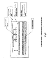
- the media bed used in the LHPF can consist of at least five layers (depending on the scale of filter) of differently sized crushed quartzite (silica) each meeting the material characteristics required for slow, rapid or pressure sand filters as stated by the American Water Works Association (AWWA).
- the upper three layers use uniform graded sizes (effective sizes of 0.15mm, 0.35mm and 1.0mm respectively).
- the top layer provides most of the filtering action.
- the bottom two layers of the media bed (1/8 to 1/2 inch and 1/2 to 1 1/2 inch (3,175 to 12,7 mm and 12,7 to 38,1 mm) respectively) allow uniform vertical flow, downward and upward, through the filtering layers while filtration is in progress and even distribution of the water across the entire bottom of the filter bed during a backwash.
- the use of crushed quartzite, rather than rounded particles of quartzite reduces the magnitude of backwash flow rates required to fluidize the top two layers.
- the maximum operating depth is selected such that the maximum hydraulic head produced across the filter bed does not result in filter bed compaction.
- top two layers must have an effective size less than 0.35 mm and the uniformity coefficient must be 2.05 or less.
- the top layer should have an effective size of 1/2 or less than the second filtering layer.
- the finest (top) underdrain layer must have an effective size at least 2 times that of the filtering layer immediately above it and have a uniformity coefficient of 2 or less.
- Underdrain layers below the upper most underdrain layer must be sufficiently large to prevent intermixing of the layers.
- the key to the invention is to size the top two layers so that they are the only layers that fluidize. Because both layers are composed of particles of distinctly different sizes and with very low uniformity coefficients, they will settle into beds in exactly the same way after every backwashing.
- the backwash flow rate is controlled so that only these two layers fluidize.
- the fluidizing that occurs is much more vigorous than simple mechanical agitation.
- the volume of backwash is limited by the maximum depth of water in the filter when cleaning. This volume is carefully calculated to conform with conventional criteria within the field of rapid sand filtration design.
- the backwash of the LHPF is only intended to break up the surface layer (where virtually all of the material is collected) and resuspend captured material. This is similar to a BSF, but unlike the LHPF, backwash process used by rapid sand filters and pressure sand filters, not only fluidizes the bed but also permits scouring and flushing of captured material from well within the filter bed itself.
- the backwash of a rapid sand or pressure sand filter must be long enough to ensure that all of the captured particles have been flushed from the interior of the media. Mechanical surface agitation might be used if normal backwash is not considered sufficient.
- the LHPF uses an underdrain system and backwash method that closely resembles the method used in pressure sand filters but it is not nearly as extensive. The reason for this is that rapid sand filters must use relatively large flow rates of backwash water at low head to fluidize a deeper media bed composed of larger particles. In comparison, the LHPF must only fluidize the uppermost two layers for a short period of time to effectively remove and suspend captured particulate material in the backwash water. When the backwash flow is stopped, the top two fluidized layers in the LHPF collapse vertically into layers resembling the original filter bed. This is because each layer has a very different effective size and both layers are comprised of uniformly graded particles. Remaining backwash water is 'squeezed' out and upward from the filter media and the cleaned media bed settles.
- the design of the underdrain system used in a LHPF is fundamentally different from that used in a BSF system.
- a very gentle reverse flow (a kind of low flow rate backwash) is used that cannot fluidize the filter bed.
- Media beds used in slow sand filters are not intended to be fluidized.
- the reverse flow used in the BSF is intended to remove any gases that have been captured within the filter media and to provide sufficient water on the surface of the media to facilitate the suspension of captured particulate material (achieved by agitating the surface of the media layer). The suspension is then removed and the filter is ready for operation.
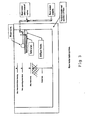
- the wastewater produced during the backwash process is removed using perforated pipes located along and attached to the interior walls of the filter.
- the holes in the pipe face slightly downward to avoid capturing any of the fluidized media. They are located approximately ten centimetres or less above the surface of the media (all of the water is not removed).
- the perforations in the underdrain pipe system must be sufficiently small to prevent any of the particles in the bottommost underdrain layer from entering the system.
- the perforated pipes are attached to a siphon spillway system that also acts as an emergency overflow system. The rate of flow through this system is controlled by a dedicated waste water flow control valve which is not greater than the capacity to take the wastewater to disposal.
- a second, waste water operations valve is used to alternatively prevent flow from the filter until backwash is completed and is then opened to facilitate the siphon evacuation process.
- the same valve is left open after backwash is completed to provide emergency overflow protection.
- the wastewater collection system and the siphon outlet system and method of control are unique. While siphon spillways per se are not novel, siphon spillways controlled and operated in the manner included in the design of the LHPF are novel.
- Pre-treatment may be useful. Effective as part of conventional treatment systems. (These include use of coagulants and clarification prior to filtration.) Effective as part of conventional treatment systems. (These include use of coagulants and clarification prior to filtration.) Very effective and practical at all turbidities. Pre-treatment may be useful. Clay Organic Oxidized Iron Effective but not usually practical. Very effective and practical. Not sufficiently effective or normally used. Not sufficiently effective or normally used. Very effective and practical. Manganese Arsenic Not used because pre-treatment impractical Very effective and practical with required pre-treatment.
Landscapes
- Life Sciences & Earth Sciences (AREA)
- Hydrology & Water Resources (AREA)
- Engineering & Computer Science (AREA)
- Environmental & Geological Engineering (AREA)
- Water Supply & Treatment (AREA)
- Chemical & Material Sciences (AREA)
- Organic Chemistry (AREA)
- Filtration Of Liquid (AREA)
- Filtering Materials (AREA)
Priority Applications (1)
| Application Number | Priority Date | Filing Date | Title |
|---|---|---|---|
| PL07719901T PL2114545T3 (pl) | 2007-01-03 | 2007-06-01 | Niskociśnieniowy piaskowy filtr czyszczący |
Applications Claiming Priority (2)
| Application Number | Priority Date | Filing Date | Title |
|---|---|---|---|
| US88319707P | 2007-01-03 | 2007-01-03 | |
| PCT/CA2007/000985 WO2008080214A1 (en) | 2007-01-03 | 2007-06-01 | Low operating head polishing sand filter |
Publications (3)
| Publication Number | Publication Date |
|---|---|
| EP2114545A1 EP2114545A1 (en) | 2009-11-11 |
| EP2114545A4 EP2114545A4 (en) | 2010-06-30 |
| EP2114545B1 true EP2114545B1 (en) | 2014-10-22 |
Family
ID=39588087
Family Applications (1)
| Application Number | Title | Priority Date | Filing Date |
|---|---|---|---|
| EP07719901.6A Not-in-force EP2114545B1 (en) | 2007-01-03 | 2007-06-01 | Low operating head polishing sand filter |
Country Status (8)
| Country | Link |
|---|---|
| US (1) | US20100072118A1 (pl) |
| EP (1) | EP2114545B1 (pl) |
| CN (1) | CN101610825B (pl) |
| CA (1) | CA2670393C (pl) |
| CO (1) | CO6180455A2 (pl) |
| ES (1) | ES2527917T3 (pl) |
| PL (1) | PL2114545T3 (pl) |
| WO (1) | WO2008080214A1 (pl) |
Families Citing this family (4)
| Publication number | Priority date | Publication date | Assignee | Title |
|---|---|---|---|---|
| US9120684B2 (en) | 2008-10-13 | 2015-09-01 | Robert R. McDonald | Chemical/biochemical water purification reactor and method of implementing same |
| ES2371192B1 (es) * | 2009-12-17 | 2013-05-07 | Ohl Medio Ambiente, Inima, S.A.U. | Filtro de pretratamiento y acondicionamiento de agua del tipo de lecho granular cerrado a presion con medios de lavado a contracorriente |
| US9359225B1 (en) | 2015-03-26 | 2016-06-07 | E. Neal Caldwell | Water filter |
| CN105293620A (zh) * | 2015-12-03 | 2016-02-03 | 重庆甘泰环保设备有限公司 | 适合场镇生活污水处理的人工快渗池 |
Family Cites Families (14)
| Publication number | Priority date | Publication date | Assignee | Title |
|---|---|---|---|---|
| US3547816A (en) * | 1967-12-01 | 1970-12-15 | Kurita Water Ind Ltd | Method and apparatus for waste water purification |
| US3817378A (en) * | 1971-06-22 | 1974-06-18 | Hydro Clear Corp | Method and apparatus for filtering solids from a liquid effluent |
| US4765892A (en) * | 1984-08-29 | 1988-08-23 | Applied Industrial Materials Corporation | Sand filter media and an improved method of purifying water |
| US4668405A (en) * | 1985-06-19 | 1987-05-26 | Process Development, Inc. | Downflow filter with high velocity backflush |
| US5032261A (en) * | 1988-05-24 | 1991-07-16 | Dufresne-Henry, Inc. | Compact biofilter for drinking water treatment |
| US5292436A (en) * | 1992-05-13 | 1994-03-08 | Kansas State University Research Foundation | Tapered bed filtration apparatus |
| CN2147031Y (zh) * | 1992-06-27 | 1993-11-24 | 殷振伟 | 双反冲压力式砂过滤器 |
| JPH06134451A (ja) * | 1992-10-29 | 1994-05-17 | Shunichi Terada | 飲料水の浄化方法 |
| US6123858A (en) * | 1993-10-27 | 2000-09-26 | University Technologies International Inc. | Slow sand filter for use with intermittently flowing water supply and method of use thereof |
| US5980755A (en) * | 1997-11-07 | 1999-11-09 | Rg, Delaware, Inc. | Methods and apparatus for monitoring a filter bed by differential pressure |
| GB2369069B (en) * | 2000-11-03 | 2005-02-09 | Spruce Internat Separations Lt | Water treatment system |
| GB2388557B (en) * | 2002-05-08 | 2006-07-12 | Spruce Internat Separations Lt | Treatment system |
| US6966980B2 (en) * | 2003-01-21 | 2005-11-22 | Humphrey Blackburn | SSF/x slow sand filter |
| CN1554590A (zh) * | 2003-12-21 | 2004-12-15 | 谢丰伟 | 一种用人造石英砂替代天然砂净化饮用水的方法 |
-
2007
- 2007-06-01 ES ES07719901.6T patent/ES2527917T3/es active Active
- 2007-06-01 CN CN200780049256.XA patent/CN101610825B/zh active Active
- 2007-06-01 US US12/516,165 patent/US20100072118A1/en not_active Abandoned
- 2007-06-01 PL PL07719901T patent/PL2114545T3/pl unknown
- 2007-06-01 EP EP07719901.6A patent/EP2114545B1/en not_active Not-in-force
- 2007-06-01 CA CA2670393A patent/CA2670393C/en active Active
- 2007-06-01 WO PCT/CA2007/000985 patent/WO2008080214A1/en not_active Ceased
-
2009
- 2009-05-14 CO CO09049144A patent/CO6180455A2/es active IP Right Grant
Also Published As
| Publication number | Publication date |
|---|---|
| ES2527917T3 (es) | 2015-02-02 |
| CO6180455A2 (es) | 2010-07-19 |
| CA2670393A1 (en) | 2008-07-10 |
| EP2114545A1 (en) | 2009-11-11 |
| US20100072118A1 (en) | 2010-03-25 |
| WO2008080214A1 (en) | 2008-07-10 |
| HK1134797A1 (en) | 2010-05-14 |
| CA2670393C (en) | 2012-05-15 |
| PL2114545T3 (pl) | 2015-04-30 |
| CN101610825A (zh) | 2009-12-23 |
| CN101610825B (zh) | 2014-05-07 |
| EP2114545A4 (en) | 2010-06-30 |
Similar Documents
| Publication | Publication Date | Title |
|---|---|---|
| JP6935336B2 (ja) | 改良された逆洗が可能な多層媒体床フィルタ | |
| CA2810635A1 (en) | Upward-type filtering apparatus characterized in laminating method of filtering material | |
| JP3652557B2 (ja) | ろ過装置の逆洗方法 | |
| EP2114545B1 (en) | Low operating head polishing sand filter | |
| USRE28458E (en) | Apparatus and method of filtering solids from a liquid effluent | |
| US20080190868A1 (en) | Water Filtration and Recycling for Stone Fabrication Equipment | |
| EP2707334B1 (en) | Biological treatment process and installation including air-lift and post-treatment in filter | |
| CN111018249A (zh) | 污水强化预处理一体化设备 | |
| Abudi | The effect of sand filter characteristics on removal efficiency of organic matter from grey water | |
| US6896818B2 (en) | Water filtration and recycling for stone fabrication equipment | |
| US3482695A (en) | Package water treatment plant | |
| JP3652567B2 (ja) | ろ過装置の洗浄方法 | |
| JP4721239B1 (ja) | ろ過材の積層方法に特徴を有する上向きろ過装置 | |
| CN211141763U (zh) | 一种水质净化系统 | |
| JP2003220305A (ja) | 移動ろ床式ろ過装置 | |
| JP3164640U (ja) | 微細な濁質除去用のろ過装置 | |
| HK1134797B (en) | Low operating head polishing sand filter | |
| CN206767745U (zh) | 一种带有反冲洗装置的生物慢滤装置 | |
| Manz et al. | Slow sand filtration—demand operated and cleaned using backwash | |
| US20070007213A1 (en) | Water filtration process and apparatus | |
| Hell et al. | Filtration in Water and Used Water Purification | |
| JP2010207743A (ja) | クリプトスポリジウムの除去方法および除去装置 | |
| US20040217066A1 (en) | Universal piping apparatus for use with a filtration device | |
| Manz et al. | MEL–Biological Filtration and MEL–Polishing Filtration Slow sand filtration–Demand Operated and Cleaned Using Backwash | |
| JPH0947604A (ja) | 浮上▲ろ▼材を使用する回分式上昇流▲ろ▼過装置 |
Legal Events
| Date | Code | Title | Description |
|---|---|---|---|
| PUAI | Public reference made under article 153(3) epc to a published international application that has entered the european phase |
Free format text: ORIGINAL CODE: 0009012 |
|
| 17P | Request for examination filed |
Effective date: 20090528 |
|
| AK | Designated contracting states |
Kind code of ref document: A1 Designated state(s): AT BE BG CH CY CZ DE DK EE ES FI FR GB GR HU IE IS IT LI LT LU LV MC MT NL PL PT RO SE SI SK TR |
|
| DAX | Request for extension of the european patent (deleted) | ||
| A4 | Supplementary search report drawn up and despatched |
Effective date: 20100528 |
|
| 17Q | First examination report despatched |
Effective date: 20110824 |
|
| GRAP | Despatch of communication of intention to grant a patent |
Free format text: ORIGINAL CODE: EPIDOSNIGR1 |
|
| INTG | Intention to grant announced |
Effective date: 20140129 |
|
| GRAP | Despatch of communication of intention to grant a patent |
Free format text: ORIGINAL CODE: EPIDOSNIGR1 |
|
| INTG | Intention to grant announced |
Effective date: 20140627 |
|
| GRAS | Grant fee paid |
Free format text: ORIGINAL CODE: EPIDOSNIGR3 |
|
| GRAA | (expected) grant |
Free format text: ORIGINAL CODE: 0009210 |
|
| AK | Designated contracting states |
Kind code of ref document: B1 Designated state(s): AT BE BG CH CY CZ DE DK EE ES FI FR GB GR HU IE IS IT LI LT LU LV MC MT NL PL PT RO SE SI SK TR |
|
| REG | Reference to a national code |
Ref country code: GB Ref legal event code: FG4D |
|
| REG | Reference to a national code |
Ref country code: CH Ref legal event code: EP |
|
| REG | Reference to a national code |
Ref country code: AT Ref legal event code: REF Ref document number: 692327 Country of ref document: AT Kind code of ref document: T Effective date: 20141115 |
|
| REG | Reference to a national code |
Ref country code: IE Ref legal event code: FG4D |
|
| REG | Reference to a national code |
Ref country code: DE Ref legal event code: R096 Ref document number: 602007038972 Country of ref document: DE Effective date: 20141204 |
|
| REG | Reference to a national code |
Ref country code: ES Ref legal event code: FG2A Ref document number: 2527917 Country of ref document: ES Kind code of ref document: T3 Effective date: 20150202 |
|
| REG | Reference to a national code |
Ref country code: NL Ref legal event code: VDEP Effective date: 20141022 |
|
| REG | Reference to a national code |
Ref country code: AT Ref legal event code: MK05 Ref document number: 692327 Country of ref document: AT Kind code of ref document: T Effective date: 20141022 |
|
| REG | Reference to a national code |
Ref country code: LT Ref legal event code: MG4D |
|
| PG25 | Lapsed in a contracting state [announced via postgrant information from national office to epo] |
Ref country code: PT Free format text: LAPSE BECAUSE OF FAILURE TO SUBMIT A TRANSLATION OF THE DESCRIPTION OR TO PAY THE FEE WITHIN THE PRESCRIBED TIME-LIMIT Effective date: 20150223 Ref country code: NL Free format text: LAPSE BECAUSE OF FAILURE TO SUBMIT A TRANSLATION OF THE DESCRIPTION OR TO PAY THE FEE WITHIN THE PRESCRIBED TIME-LIMIT Effective date: 20141022 Ref country code: IS Free format text: LAPSE BECAUSE OF FAILURE TO SUBMIT A TRANSLATION OF THE DESCRIPTION OR TO PAY THE FEE WITHIN THE PRESCRIBED TIME-LIMIT Effective date: 20150222 Ref country code: LT Free format text: LAPSE BECAUSE OF FAILURE TO SUBMIT A TRANSLATION OF THE DESCRIPTION OR TO PAY THE FEE WITHIN THE PRESCRIBED TIME-LIMIT Effective date: 20141022 Ref country code: FI Free format text: LAPSE BECAUSE OF FAILURE TO SUBMIT A TRANSLATION OF THE DESCRIPTION OR TO PAY THE FEE WITHIN THE PRESCRIBED TIME-LIMIT Effective date: 20141022 |
|
| REG | Reference to a national code |
Ref country code: PL Ref legal event code: T3 |
|
| PG25 | Lapsed in a contracting state [announced via postgrant information from national office to epo] |
Ref country code: GR Free format text: LAPSE BECAUSE OF FAILURE TO SUBMIT A TRANSLATION OF THE DESCRIPTION OR TO PAY THE FEE WITHIN THE PRESCRIBED TIME-LIMIT Effective date: 20150123 Ref country code: SE Free format text: LAPSE BECAUSE OF FAILURE TO SUBMIT A TRANSLATION OF THE DESCRIPTION OR TO PAY THE FEE WITHIN THE PRESCRIBED TIME-LIMIT Effective date: 20141022 Ref country code: LV Free format text: LAPSE BECAUSE OF FAILURE TO SUBMIT A TRANSLATION OF THE DESCRIPTION OR TO PAY THE FEE WITHIN THE PRESCRIBED TIME-LIMIT Effective date: 20141022 Ref country code: AT Free format text: LAPSE BECAUSE OF FAILURE TO SUBMIT A TRANSLATION OF THE DESCRIPTION OR TO PAY THE FEE WITHIN THE PRESCRIBED TIME-LIMIT Effective date: 20141022 Ref country code: CY Free format text: LAPSE BECAUSE OF FAILURE TO SUBMIT A TRANSLATION OF THE DESCRIPTION OR TO PAY THE FEE WITHIN THE PRESCRIBED TIME-LIMIT Effective date: 20141022 |
|
| REG | Reference to a national code |
Ref country code: DE Ref legal event code: R097 Ref document number: 602007038972 Country of ref document: DE |
|
| PG25 | Lapsed in a contracting state [announced via postgrant information from national office to epo] |
Ref country code: EE Free format text: LAPSE BECAUSE OF FAILURE TO SUBMIT A TRANSLATION OF THE DESCRIPTION OR TO PAY THE FEE WITHIN THE PRESCRIBED TIME-LIMIT Effective date: 20141022 Ref country code: DK Free format text: LAPSE BECAUSE OF FAILURE TO SUBMIT A TRANSLATION OF THE DESCRIPTION OR TO PAY THE FEE WITHIN THE PRESCRIBED TIME-LIMIT Effective date: 20141022 Ref country code: CZ Free format text: LAPSE BECAUSE OF FAILURE TO SUBMIT A TRANSLATION OF THE DESCRIPTION OR TO PAY THE FEE WITHIN THE PRESCRIBED TIME-LIMIT Effective date: 20141022 Ref country code: SK Free format text: LAPSE BECAUSE OF FAILURE TO SUBMIT A TRANSLATION OF THE DESCRIPTION OR TO PAY THE FEE WITHIN THE PRESCRIBED TIME-LIMIT Effective date: 20141022 Ref country code: RO Free format text: LAPSE BECAUSE OF FAILURE TO SUBMIT A TRANSLATION OF THE DESCRIPTION OR TO PAY THE FEE WITHIN THE PRESCRIBED TIME-LIMIT Effective date: 20141022 |
|
| PLBE | No opposition filed within time limit |
Free format text: ORIGINAL CODE: 0009261 |
|
| STAA | Information on the status of an ep patent application or granted ep patent |
Free format text: STATUS: NO OPPOSITION FILED WITHIN TIME LIMIT |
|
| 26N | No opposition filed |
Effective date: 20150723 |
|
| PG25 | Lapsed in a contracting state [announced via postgrant information from national office to epo] |
Ref country code: MC Free format text: LAPSE BECAUSE OF FAILURE TO SUBMIT A TRANSLATION OF THE DESCRIPTION OR TO PAY THE FEE WITHIN THE PRESCRIBED TIME-LIMIT Effective date: 20141022 |
|
| REG | Reference to a national code |
Ref country code: CH Ref legal event code: PL |
|
| PG25 | Lapsed in a contracting state [announced via postgrant information from national office to epo] |
Ref country code: LU Free format text: LAPSE BECAUSE OF FAILURE TO SUBMIT A TRANSLATION OF THE DESCRIPTION OR TO PAY THE FEE WITHIN THE PRESCRIBED TIME-LIMIT Effective date: 20150601 Ref country code: SI Free format text: LAPSE BECAUSE OF FAILURE TO SUBMIT A TRANSLATION OF THE DESCRIPTION OR TO PAY THE FEE WITHIN THE PRESCRIBED TIME-LIMIT Effective date: 20141022 |
|
| PG25 | Lapsed in a contracting state [announced via postgrant information from national office to epo] |
Ref country code: CH Free format text: LAPSE BECAUSE OF NON-PAYMENT OF DUE FEES Effective date: 20150630 Ref country code: LI Free format text: LAPSE BECAUSE OF NON-PAYMENT OF DUE FEES Effective date: 20150630 |
|
| REG | Reference to a national code |
Ref country code: FR Ref legal event code: PLFP Year of fee payment: 10 |
|
| PG25 | Lapsed in a contracting state [announced via postgrant information from national office to epo] |
Ref country code: MT Free format text: LAPSE BECAUSE OF FAILURE TO SUBMIT A TRANSLATION OF THE DESCRIPTION OR TO PAY THE FEE WITHIN THE PRESCRIBED TIME-LIMIT Effective date: 20141022 |
|
| PG25 | Lapsed in a contracting state [announced via postgrant information from national office to epo] |
Ref country code: BG Free format text: LAPSE BECAUSE OF FAILURE TO SUBMIT A TRANSLATION OF THE DESCRIPTION OR TO PAY THE FEE WITHIN THE PRESCRIBED TIME-LIMIT Effective date: 20141022 Ref country code: HU Free format text: LAPSE BECAUSE OF FAILURE TO SUBMIT A TRANSLATION OF THE DESCRIPTION OR TO PAY THE FEE WITHIN THE PRESCRIBED TIME-LIMIT; INVALID AB INITIO Effective date: 20070601 |
|
| REG | Reference to a national code |
Ref country code: FR Ref legal event code: PLFP Year of fee payment: 11 |
|
| PG25 | Lapsed in a contracting state [announced via postgrant information from national office to epo] |
Ref country code: BE Free format text: LAPSE BECAUSE OF FAILURE TO SUBMIT A TRANSLATION OF THE DESCRIPTION OR TO PAY THE FEE WITHIN THE PRESCRIBED TIME-LIMIT Effective date: 20141022 |
|
| REG | Reference to a national code |
Ref country code: FR Ref legal event code: PLFP Year of fee payment: 12 |
|
| PGFP | Annual fee paid to national office [announced via postgrant information from national office to epo] |
Ref country code: PL Payment date: 20190521 Year of fee payment: 13 Ref country code: IT Payment date: 20190621 Year of fee payment: 13 Ref country code: IE Payment date: 20190627 Year of fee payment: 13 |
|
| PGFP | Annual fee paid to national office [announced via postgrant information from national office to epo] |
Ref country code: TR Payment date: 20190524 Year of fee payment: 13 Ref country code: FR Payment date: 20190625 Year of fee payment: 13 |
|
| PGFP | Annual fee paid to national office [announced via postgrant information from national office to epo] |
Ref country code: GB Payment date: 20190627 Year of fee payment: 13 Ref country code: DE Payment date: 20190627 Year of fee payment: 13 Ref country code: ES Payment date: 20190701 Year of fee payment: 13 |
|
| REG | Reference to a national code |
Ref country code: DE Ref legal event code: R119 Ref document number: 602007038972 Country of ref document: DE |
|
| GBPC | Gb: european patent ceased through non-payment of renewal fee |
Effective date: 20200601 |
|
| PG25 | Lapsed in a contracting state [announced via postgrant information from national office to epo] |
Ref country code: IE Free format text: LAPSE BECAUSE OF NON-PAYMENT OF DUE FEES Effective date: 20200601 Ref country code: FR Free format text: LAPSE BECAUSE OF NON-PAYMENT OF DUE FEES Effective date: 20200630 Ref country code: GB Free format text: LAPSE BECAUSE OF NON-PAYMENT OF DUE FEES Effective date: 20200601 |
|
| PG25 | Lapsed in a contracting state [announced via postgrant information from national office to epo] |
Ref country code: DE Free format text: LAPSE BECAUSE OF NON-PAYMENT OF DUE FEES Effective date: 20210101 |
|
| REG | Reference to a national code |
Ref country code: ES Ref legal event code: FD2A Effective date: 20211026 |
|
| PG25 | Lapsed in a contracting state [announced via postgrant information from national office to epo] |
Ref country code: IT Free format text: LAPSE BECAUSE OF NON-PAYMENT OF DUE FEES Effective date: 20200601 |
|
| PG25 | Lapsed in a contracting state [announced via postgrant information from national office to epo] |
Ref country code: ES Free format text: LAPSE BECAUSE OF NON-PAYMENT OF DUE FEES Effective date: 20200602 |
|
| PG25 | Lapsed in a contracting state [announced via postgrant information from national office to epo] |
Ref country code: TR Free format text: LAPSE BECAUSE OF NON-PAYMENT OF DUE FEES Effective date: 20200601 |
|
| PG25 | Lapsed in a contracting state [announced via postgrant information from national office to epo] |
Ref country code: PL Free format text: LAPSE BECAUSE OF NON-PAYMENT OF DUE FEES Effective date: 20200601 |