EP2113815A2 - Developing unit - Google Patents
Developing unit Download PDFInfo
- Publication number
- EP2113815A2 EP2113815A2 EP09004497A EP09004497A EP2113815A2 EP 2113815 A2 EP2113815 A2 EP 2113815A2 EP 09004497 A EP09004497 A EP 09004497A EP 09004497 A EP09004497 A EP 09004497A EP 2113815 A2 EP2113815 A2 EP 2113815A2
- Authority
- EP
- European Patent Office
- Prior art keywords
- side seal
- downstream side
- developer
- developer carrier
- upstream side
- Prior art date
- Legal status (The legal status is an assumption and is not a legal conclusion. Google has not performed a legal analysis and makes no representation as to the accuracy of the status listed.)
- Granted
Links
- 238000011144 upstream manufacturing Methods 0.000 claims abstract description 61
- 238000007789 sealing Methods 0.000 claims abstract description 22
- 230000001105 regulatory effect Effects 0.000 claims description 21
- 239000002184 metal Substances 0.000 description 14
- 238000000034 method Methods 0.000 description 8
- 238000010438 heat treatment Methods 0.000 description 4
- 239000002390 adhesive tape Substances 0.000 description 3
- 239000000835 fiber Substances 0.000 description 2
- JOYRKODLDBILNP-UHFFFAOYSA-N Ethyl urethane Chemical compound CCOC(N)=O JOYRKODLDBILNP-UHFFFAOYSA-N 0.000 description 1
- 229920006311 Urethane elastomer Polymers 0.000 description 1
- 230000002411 adverse Effects 0.000 description 1
- 239000000428 dust Substances 0.000 description 1
- 230000000694 effects Effects 0.000 description 1
- 229920001971 elastomer Polymers 0.000 description 1
- 238000012986 modification Methods 0.000 description 1
- 230000004048 modification Effects 0.000 description 1
- 239000002759 woven fabric Substances 0.000 description 1
Images


Classifications
-
- G—PHYSICS
- G03—PHOTOGRAPHY; CINEMATOGRAPHY; ANALOGOUS TECHNIQUES USING WAVES OTHER THAN OPTICAL WAVES; ELECTROGRAPHY; HOLOGRAPHY
- G03G—ELECTROGRAPHY; ELECTROPHOTOGRAPHY; MAGNETOGRAPHY
- G03G15/00—Apparatus for electrographic processes using a charge pattern
- G03G15/06—Apparatus for electrographic processes using a charge pattern for developing
- G03G15/08—Apparatus for electrographic processes using a charge pattern for developing using a solid developer, e.g. powder developer
- G03G15/0806—Apparatus for electrographic processes using a charge pattern for developing using a solid developer, e.g. powder developer on a donor element, e.g. belt, roller
- G03G15/0817—Apparatus for electrographic processes using a charge pattern for developing using a solid developer, e.g. powder developer on a donor element, e.g. belt, roller characterised by the lateral sealing at both sides of the donor member with respect to the developer carrying direction
Definitions
- the present invention relates to a developing unit provided with a side seal member that seals between an end part of a developing roller and a developing unit housing.
- Japanese patent publication 2001-22179A discloses a side seal member that is provided between an end part of a rotatable developing roller and a developing unit housing and that is located adjacent to a developer supply port of the developing unit housing.
- the side sealing member includes an upstream side base, a downstream side base and a felt member adhered to the upper surfaces of the upstream and downstream bases.
- developer entering the felt member may be moved in a direction away from the supply port by sliding contact between the felt member and the developing roller to cause toner leakage.
- the present invention was made in view of the above-noted and/or other circumstances.
- the present invention can provide a developing unit including a developer carrier; a housing; and a side sealing member disposed between an end part of the developer carrier and a portion of the housing adjacent to a supply port.
- the side sealing member includes an upstream side seal and a downstream side seal.
- the upstream side seal is configured to convey a developer on the upstream side seal in an oblique direction toward the supply port and the downstream side.
- the downstream side seal is configured to convey a developer on the downstream side seal in a direction toward the downstream side.
- the present invention can provide a developing unit capable of preventing developer from leaking.
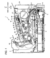
- Fig. 1 is a side sectional view showing a laser printer having a development cartridge.
- Fig. 2 is a side sectional view showing the development cartridge.
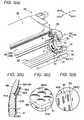
- Fig. 3(a) is an enlarged perspective view showing a structure of a side sealing member
- Fig. 3(b) is a sectional view showing details of the side sealing member
- Fig. 3(c) is an enlarged perspective view of a portion X of Fig. 3(a)
- Fig. 3(d) is an enlarged perspective view of a portion Y of Fig. 3(a) .
- Fig. 4 is a front elevational view showing directions in which toner is conveyed by an upstream side seal and a downstream side seal.
- Fig. 1 is a side sectional view showing a laser printer provided with a development cartridge
- Fig. 2 is a side sectional view showing the development cartridge.
- the directions are specified based on a user who uses the laser printer 1. That is, in Fig. 1 , the right side is called the “near side”, the left side is called the “back side”, the back side in the perpendicular direction of the paper is called the "right side”, and the near side in the perpendicular direction of the paper is called the "left side”.
- the laser printer 1 includes a main casing 2, and a feeder portion 4 for feeding sheets 3 and an image forming portion 5 for forming images on a sheet 3, which are located inside the main casing 2.
- the feeder portion 4 includes a sheet feeding tray 6 removably mounted to the inner bottom of the main casing 2 and a sheet pressing plate 7 disposed inside the sheet feeding tray 6.
- the feeder portion 4 has various rollers 11 for conveying sheets 3 and removing paper dust.
- the feeder portion 4 functions so that sheets 3 in the sheet feeding tray 6 are biased upward by the sheet pressing plate 7 and are conveyed to the image forming portion 5 by the rollers 11.
- the image forming portion 5 includes a scanner unit 16, a process cartridge 17 and a fixing unit 18.
- the scanner unit 16 is disposed in the inner upper part of the main casing 2 and includes a laser beam emitting portion (not illustrated), a polygon mirror 19 driven to turn, lenses 20, 21, and reflection mirrors 22, 23 and 24.
- a laser beam passes thought the scanner unit 16 along a path shown by a chain line in Fig. 1 to be irradiated on the surface of a photosensitive drum 27 for scanning at high speed.
- the process cartridge 17 is removable from and mountable to the main casing 2 when a front cover 2a at the near side of the main casing 2 is open.
- the process cartridge 17 includes a development cartridge 28 as an example of a developing unit and a drum unit 39.
- the development cartridge 28 is removable from and mountable to the main casing 2 in a state where the development cartridge 28 is mounted to the drum unit 39.
- the drum unit 39 may be fixed to the main casing 2, and the development cartridge 28 per se may be removably mountable to the drum unit 39 fixed to the main casing 2.
- the development cartridge 28 includes a developing roller 31 as an example of a developer carrier, a layer thickness regulating blade 32 as an example of a layer thickness regulating member, a supply roller 33 and a developer accommodating chamber 34.
- toner as an example of a developer in the developer accommodating chamber 34 is agitated by an agitator 34A and thereafter supplied to the developing roller 31 by the supply roller 33.
- the toner is supplied to the developing roller 31 by the supply roller 33, the toner is positively friction-charged between the supply roller 33 and the developing roller 31.
- the developing roller 31 rotates, the toner supplied onto the developing roller 31 enters between the layer thickness regulating blade 32 and the developing roller 31 so that the toner is further friction-charged while the toner on the developing roller 31 is regulated to a constant thickness. This way, a thin layer of the toner is carried on the developing roller 31.
- a detailed description will be given later of the development cartridge 28.
- the drum unit 39 includes a photosensitive drum 27, a Scorotron type charger 29 and a transfer roller 30.
- the surface of the photosensitive drum 27 in this drum unit 39 is positively charged uniformly by the Scorotron type charger 29 and thereafter exposed by a high-speed scanning of the laser beam emitted from the scanner unit 16. Consequently, the potential at the exposed portion is lowered to form an electrostatic latent image based on image data.
- the toner carried on the developing roller 31 is supplied to the electrostatic latent image formed on the surface of the photosensitive drum 27 to form a toner image on the surface of the photosensitive drum 27. Thereafter, a sheet 3 is conveyed between the photosensitive drum 27 and the transfer roller 30 so that the toner image carried on the surface of the photosensitive drum 27 is transferred onto the sheet 3.
- the fixing unit 18 includes a heating roller 41 and a pressing roller 42 disposed opposite the heating roller 41 to press the heating roller 41.
- a heating roller 41 and a pressing roller 42 disposed opposite the heating roller 41 to press the heating roller 41.
- toner transferred on the sheet 3 is thermally fixed to the sheet 3.
- the sheet 3 having the toner image thermally fixed by the fixing unit 18 is conveyed to a discharge roller 45 disposed at the downstream side of the fixing unit 18 to be fed out from the discharge roller 45 onto a discharge tray 46.
- Fig. 3(a) is an enlarged perspective view showing the structure around a side sealing member
- Fig. 3(b) is a sectional view showing the details of the side sealing member
- Fig. 3(c) is an enlarged perspective view of X portion in Fig. 3(a)
- Fig. 3(d) is an enlarged perspective view of Y portion in Fig. 3(a)
- Fig. 4 is a front elevational view showing a direction in which a toner is fed by an upstream side seal and a downstream side seal. Since the development cartridge 28 is of a left-right symmetrical structure, Fig. 3 and Fig. 4 show only the left side thereof with the right side thereof omitted. In addition, Fig. 3 and Fig. 4 show a state where the developing roller 31 and the supply roller 33 are removed.
- the development cartridge 28 includes a developing unit housing 50 that rotatably supports the developing roller 31, and a side sealing member 60 that is brought into sliding contact with corresponding one of end parts of the developing roller 31, in addition to the developing roller 31, etc. described above.
- the developing unit housing 50 includes a bearing portion 51 that rotatably supports the developing roller 31, a supply port 52 for supplying toner from the internal toner accommodating chamber 34 to the developing roller 31, and an attaching face 53, the side view of which is arc-shaped.
- the attaching face 53 is disposed adjacent to each of left and right sides of the supply port 52 (the attaching face 53 disposed adjacent to the left side of the supply port 52 is only shown in Fig. 3(a) ).
- the supply port 52 is in the form of a rectangular long hole elongating in the axial direction of the developing roller 31, and the layer thickness regulating blade 32 is fixed to the housing 50 at the upper part of the supply port 52.
- the layer thickness regulating blade 32 includes a metal plate 32A, the upper end part of which is fixed to the developing unit housing 50, and a rubber pressing member 32B, as an example of a pressing portion, fixed to the lower edge (distal end) of the metal plate 32A.
- the metal plate 32A has such a length as to protrude outside the left and right edges of the supply port 52 in the right-left direction, and the metal plate 32A is fixed at the upper side corner parts of left and right end parts thereof to the developing unit housing 50 with screws S.
- the pressing member 32B has such a length that the pressing member protrudes outside the left and right edges of the supply port 52 in the right-left direction but the left and right edges of the pressing member 32B are positioned inside the left and right edges of the metal plate 32A in the right-left direction (see Fig. 4 ).
- the pressing member 32B is brought into sliding contact with the outer circumferential surface of the developing roller 31, while receiving a basing force from the metal plate 32A.
- the side sealing member 60 is disposed between corresponding one of the end parts of the developing roller 31 and corresponding one of the attaching faces 53 of the developing unit housing 50 adjacent to the left and right sides of the supply port 52 in the developing unit housing 50.
- the side sealing member 60 includes an upstream side seal 61 and a downstream side seal 62.
- the upstream side seal 61 includes an elastic base 61A and a surface member 61B provided to a surface of the base 61A facing the developing roller 31.
- the base 61A is formed of an elastic member made, for example, from a urethane sponge, and is adhered directly to the attaching face 53 of the developing unit housing 50 by a double-side adhesive tape T.
- the surface member 61B is constructed such that plural capillary members (fibrous members) C are implanted on a base sheet BS, and the surface member 61B thus constructed is adhered to the base 61A by a double-side adhesive tape T.
- the surface member 61B is constructed such that capillary bundles CB, each having plural capillary members C bundled together, are arrayed at an interval, and that each capillary bundle CB is tilted in an oblique direction so that a portion of the capillary bundle CB is closer to the supply port 52 as the portion of the capillary bundle CB is closer to the downstream side in the rotational direction of the developing roller 31 (in the direction indicated by an arrow in Fig. 3(a) and 3(c) )).
- plural rows are arranged at an interval, each row having plural capillary bundles CB arranged at an interval in the above-mention oblique.
- This arrangement can form first guide paths G1 on the surface member 61B between the capillary bundles GB to feed toner in the above-mentioned oblique direction.
- the upstream side seal 61 thus constructed has a width larger in the right-left direction than a width of the downstream side seal 62 to extend toward the supply port 52 beyond the downstream side seal 62.
- the surface member 61B can be formed in the following manner: The capillary bundles CB are implanted on a sheet member, the capillary bundles CB on the sheet member are kept tilted in a given direction for a time period so that the capillary bundles CB have a tilting tendency, and thereafter the sheet member with the capillary bundles CB is longitudinally and laterally cut to obtain plural base sheets BS.
- This method is advantageous in comparison with a method of cutting a sheet member into plural base sheets BS in advance of giving a tilting tendency to capillary bundles CB because tips of capillary members do not protrude from the base sheet BS according to this method.
- the tips of capillary members protruding from the base sheet toward the supply port may adversely scrap off toner from the developing roller 31, and therefore the surface member 61B constructed according to this method can contributes to maintaining image quality. That is, toner carried on an image-forming range of the developing roller 31 can be prevented from being scrapped off by capillary members.
- the length of implanted capillary members C and the spacing between the capillary bundles CB are shown enlarged for convenience of explanation. Therefore, for example, the length of capillary members C may be made shorter than the length found from these figures, and the capillary bundles may be disposed at a higher density on the entire surface of the base sheet BS than the density found from these figures.
- the downstream side seal 62 is disposed at the downstream side, in the rotational direction, of the developing roller 31 relative to the upstream side seal 61.
- the downstream side seal 62 includes an elastic base 62A and a surface member 62B attached to a surface of the base 62A facing the developing roller 31.
- the base 62A is an elastic member made, for example, from urethane rubber, and is adhered to the metal plate 32A of the layer thickness regulating blade 32 by a double-sided adhesive tape T so as to protrude from the metal plate 32A toward the upstream side.
- the surface member 62B includes plural capillary bundles CB and a base sheet BS similarly to the surface member 61B of the upstream side 61.
- the capillary bundles CB on the surface member 62B are tilted in a direction different from the direction in which the capillary bundles CB on the surface member 61B of the upstream side seal 61 are tilted.
- the surface member 62B is constructed such that plural rows are arranged at an interval in the axial direction of the developing roller 31, each row having plural capillary bundles CB arranged at an interval in the rotational direction of the developing roller 31, and that the capillary bundles CB are tilted toward the downstream side to extend in the rotational direction of the developing roller 31. Consequently, the second guide paths G2, along which toner can be fed toward the downstream side in the rotational direction, are formed on the surface member 62B between the capillary0 bundles CB.
- the surface member 62B has a length longer in the rotational direction than a length of the base 62A so that the surface member 62B extends toward the upstream side in the rotational direction beyond the base 62A as shown in Fig. 3(b) .
- the extension portion of the surface member 62B which protrudes from the base 62A toward the upstream side in the rotational direction, is disposed between the base 61A of the upstream side seal 61 and the surface member 61B thereof. Accordingly, the surface member 61B of the upstream side seal 61 overlaps the surface member 62B of the downstream side seal 62.
- the downstream side seal 62 (the base 62A and the surface member 62B) thus constructed is disposed on the layer thickness regulating blade 32 so as to be closely contacted with corresponding one of left and right end edges BE of the pressing member 32B of the layer thickness regulating blade 32 (in Fig. 4 , the downstream side seal 62 closely contacted with the left end edge BE of the pressing member 32B is shown).
- another seal member SM other than the side sealing member 60 is disposed between the layer thickness regulating blade 32 (metal plate 32A) and the attaching face 53 of the developing unit housing 50.
- the side sealing member 60 constructed as described above is attached to the layer thickness regulating blade 32 (metal plate 32A) to hang from the film thickness regulating blade 32 (metal plate 32A) prior to attachment of the layer thickness regulating blade 32 to the developing unit housing 50.
- the layer thickness regulating blade 32 having the side sealing member 60 is fixed to the developing unit housing 50 by screws S, and the base 61A of the upstream side seal 61 is adhered to the attaching face 53 of the developing unit housing 50.
- a recessed developer receiver 70 that is open only upward is formed at the upstream side of the upstream side seal 61.
- the developer receiver 70 is formed by a bottom wall part 71 (a part of the attaching face 53) of the housing 50, an inner wall part (right wall part in Fig. 3(a) ) 72 of the housing 50, an outer wall part (left wall part in Fig. 3(b) ) 73 of the housing 50, a back side (upstream side) end face 74 of the upstream side seal 61 and a flexible sheet member 75 attached to back side end parts of the bottom wall part 71, the inner wall part 72 and the outer wall part 73.
- toner on the upstream side seal 61 is pushed by the rotating developing roller 31 so that the toner is moved along the first guide paths G1 between the obliquely tilted capillary bundles CB (or along spaces between the capillary members C of the capillary bundles CB) as shown in Fig. 4 . Accordingly, the toner is moved toward the supply port 52 and returned to the supply port 52.
- toner on the downstream side seal 62 is pushed by the rotating developing roller 31 so that the toner is moved toward the downstream side along the second guide paths G2 between the capillary bundles CB tilted toward the downstream side in the rotational direction (or spaces between capillary members C of the capillary bundles CB). Accordingly, the toner is carried by the developing roller 31 during the movement of the toner on the downstream side seal 62 toward the downstream side in the rotational direction, and therefore the toner is conveyed by the developing roller 31 to be returned to the upstream side seal 61.
- the toner returned to the upstream side seal 61 is obliquely moved on the upstream side seal 61 to be returned to the supply port 52 as described above.
- the upstream side seal 61 can feed the toner obliquely to return the toner to the supply port 52. Accordingly, it is possible to prevent toner from leaking.
- the upstream side seal 61 and the downstream side seal 62 are arranged so that the surface member 61B of the upstream side seal 61 is disposed on and overlapped with the surface member 62B of the downstream side seal 62, it is possible to prevent the downstream side seal 62 from being turned over by rotation of the developing roller 31.
- downstream side seal 62 is closely contacted with the end edge BE of the pressing member 32B of the layer thickness regulating blade 32, toner can be prevented from leaking therebetween.
- the recessed developer receiver 70 is formed at the upstream side of the upstream side seal 61, the developer receiver 70 can receive toner even in a case where toner conveyed from the downstream side seal 62 by the developing roller 31 is scraped and dropped by the edge of the upstream side seal 61. Therefore, it is possible to prevent toner from leaking from the development cartridge 28.
- the capillary bundles CB preferably have such a length that a tip of a capillary bundle CB can contact a root portion of an adjacent capillary bundle CB. This is because toner can be prevented from flowing out from one guide path G1, G2 to an adjacent guide path G1, G2, and thus the flow of toner can be smoothened.
- the capillary bundles CB are tilted in a given direction to feed toner in the given direction.
- the present invention is not limited thereto.
- plural rows, each having capillary bundles standing upright from the base sheet and being arranged closely to one another in the given direction (the oblique direction or the rotational direction as described above) may be provided to feed toner in the given direction.
- such a woven fabric that yarns exposed therefrom to the developing roller 31 are oriented in the given direction (the oblique direction or the rotational direction as described above) may be used to feed toner in the given direction.
- plural capillary members may be densely arranged on the entire surface of the base sheet to tilt toward the downstream side, to thereby feed toner along the capillary members.
- the downstream side seal is not necessarily configured to convey toner toward the downstream side, and for example, a felt member in which fibers are not unidirectional may be adopted as the downstream side seal.
- the surface member 62B of the downstream side seal 62 protrudes from the base 62A toward the upstream side.
- the surface member 61B of the upstream side seal 61 may protrude from the base 61A toward the downstream side.
- the surface member 61B of the upstream side seal 61 can be disposed on and overlapped with the surface member 62B of the downstream side seal 62, it is also possible to prevent the downstream side seal 62 from being turned over by rotation of the developing roller 31.
- the downstream side seal 62 is adhered to the metal plate 32A of the layer thickness regulating blade 32.
- the present invention is not limited thereto.
- the downstream side seal 62 may be adhered directly to the developing unit housing 50.
- the development cartridge 28 integrally provided with the toner accommodating chamber 34 is adopted as an example of the developing unit.
- the present invention is not limited thereto.
- a cartridge to which a separate toner cartridge having a toner accommodating chamber is removably mountable may be adopted as the developing unit.
- toner is conveyed using the guide path G1, G2 between the capillary bundles CB tilted in a given direction.
- the present invention is not limited thereto.
- Capillary members densely provided on the entire surface of the base sheet and tilted in the given direction may be used to convey toner along the capillary members.
- the present invention can provide at least the following illustrative, non-limiting embodiment:
- a developing unit including: a developer carrier for carrying a developer; a developing unit housing that rotatably supports the developer carrier and that has a supply port for supplying the developer to the developer carrier; a side sealing member that is disposed between one of end parts of the developer carrier and a portion of the developing unit housing adjacent to the supply port and that is slidingly contactactable with the developer carrier; wherein the side sealing member includes an upstream side seal and a downstream side seal that is disposed in a downstream side in a rotational direction relative to the upstream side seal; the upstream side seal is configured to convey the developer in an oblique direction toward the supply port and the downstream side, and the downstream side seal is configured to convey the developer toward the downstream side.
- rotational direction means a direction in which the developer carrier slidingly contacts with the side sealing member.
- the developer on the upstream side seal is moved in the oblique direction toward the supply port and the downstream side when the developer carrier is rotated in the rotational direction, to be returned to the supply port.
- the developer on the downstream side seal is moved to the downstream side when the developer carrier is rotated in the rotational direction.
- the developer carrier carries and conveys the developer to return the developer to the upstream side seal.
- the developer returned to the upstream side seal is moved in the oblique direction to be returned to the supply port. Accordingly, it is possible to prevent the developer from leaking.
Landscapes
- Physics & Mathematics (AREA)
- General Physics & Mathematics (AREA)
- Dry Development In Electrophotography (AREA)
- Electrophotography Configuration And Component (AREA)
Abstract
Description
- The present disclosure relates to the subject matter contained in Japanese patent application No.
2008-118386 filed on April 30, 2008 - The present invention relates to a developing unit provided with a side seal member that seals between an end part of a developing roller and a developing unit housing.
- Japanese patent publication
2001-22179A USP6,336,014 ) discloses a side seal member that is provided between an end part of a rotatable developing roller and a developing unit housing and that is located adjacent to a developer supply port of the developing unit housing. The side sealing member includes an upstream side base, a downstream side base and a felt member adhered to the upper surfaces of the upstream and downstream bases. - Because fibers of the felt member are not unidirectional, developer entering the felt member may be moved in a direction away from the supply port by sliding contact between the felt member and the developing roller to cause toner leakage.
- The present invention was made in view of the above-noted and/or other circumstances.
- As one of illustrative, non-limiting embodiments, the present invention can provide a developing unit including a developer carrier; a housing; and a side sealing member disposed between an end part of the developer carrier and a portion of the housing adjacent to a supply port. The side sealing member includes an upstream side seal and a downstream side seal. The upstream side seal is configured to convey a developer on the upstream side seal in an oblique direction toward the supply port and the downstream side. The downstream side seal is configured to convey a developer on the downstream side seal in a direction toward the downstream side.
- Accordingly, as one of advantages, the present invention can provide a developing unit capable of preventing developer from leaking. The above-noted advantage and other advantages of the present invention will be described in detail with reference to the accompanying drawings.
-
Fig. 1 is a side sectional view showing a laser printer having a development cartridge. -
Fig. 2 is a side sectional view showing the development cartridge. -
Fig. 3(a) is an enlarged perspective view showing a structure of a side sealing member,Fig. 3(b) is a sectional view showing details of the side sealing member,Fig. 3(c) is an enlarged perspective view of a portion X ofFig. 3(a), and Fig. 3(d) is an enlarged perspective view of a portion Y ofFig. 3(a) . -
Fig. 4 is a front elevational view showing directions in which toner is conveyed by an upstream side seal and a downstream side seal. - A detailed description is given of an exemplary embodiment with reference to the drawings.
Fig. 1 is a side sectional view showing a laser printer provided with a development cartridge, andFig. 2 is a side sectional view showing the development cartridge. In the following description, the directions are specified based on a user who uses the laser printer 1. That is, inFig. 1 , the right side is called the "near side", the left side is called the "back side", the back side in the perpendicular direction of the paper is called the "right side", and the near side in the perpendicular direction of the paper is called the "left side". In addition, since the up-down direction in the drawings is coincident with the up-down direction specified based on a user who uses the printer, the "up-down" direction is simply used. These directions are intended to facilitate understanding of the structure of the printer 1 and should not be interpreted in a restrictive sense. - (Entire configuration of laser printer)
- As shown in
Fig. 1 , the laser printer 1 includes amain casing 2, and a feeder portion 4 forfeeding sheets 3 and animage forming portion 5 for forming images on asheet 3, which are located inside themain casing 2. - (Configuration of feeder portion)
- The feeder portion 4 includes a
sheet feeding tray 6 removably mounted to the inner bottom of themain casing 2 and a sheet pressing plate 7 disposed inside thesheet feeding tray 6. The feeder portion 4 hasvarious rollers 11 forconveying sheets 3 and removing paper dust. The feeder portion 4 functions so thatsheets 3 in thesheet feeding tray 6 are biased upward by the sheet pressing plate 7 and are conveyed to theimage forming portion 5 by therollers 11. - (Configuration of image forming portion)
- The
image forming portion 5 includes ascanner unit 16, aprocess cartridge 17 and afixing unit 18. - (Configuration of scanner unit)
- The
scanner unit 16 is disposed in the inner upper part of themain casing 2 and includes a laser beam emitting portion (not illustrated), apolygon mirror 19 driven to turn,lenses reflection mirrors scanner unit 16 along a path shown by a chain line inFig. 1 to be irradiated on the surface of aphotosensitive drum 27 for scanning at high speed. - (Configuration of process cartridge)
- The
process cartridge 17 is removable from and mountable to themain casing 2 when afront cover 2a at the near side of themain casing 2 is open. Theprocess cartridge 17 includes adevelopment cartridge 28 as an example of a developing unit and adrum unit 39. - The
development cartridge 28 is removable from and mountable to themain casing 2 in a state where thedevelopment cartridge 28 is mounted to thedrum unit 39. Alternatively, thedrum unit 39 may be fixed to themain casing 2, and thedevelopment cartridge 28 per se may be removably mountable to thedrum unit 39 fixed to themain casing 2. As shown inFig. 2 , thedevelopment cartridge 28 includes a developingroller 31 as an example of a developer carrier, a layer thickness regulatingblade 32 as an example of a layer thickness regulating member, asupply roller 33 and adeveloper accommodating chamber 34. - In the
development cartridge 28, toner as an example of a developer in thedeveloper accommodating chamber 34 is agitated by anagitator 34A and thereafter supplied to the developingroller 31 by thesupply roller 33. When the toner is supplied to the developingroller 31 by thesupply roller 33, the toner is positively friction-charged between thesupply roller 33 and the developingroller 31. As the developingroller 31 rotates, the toner supplied onto the developingroller 31 enters between the layer thickness regulatingblade 32 and the developingroller 31 so that the toner is further friction-charged while the toner on the developingroller 31 is regulated to a constant thickness. This way, a thin layer of the toner is carried on the developingroller 31. A detailed description will be given later of thedevelopment cartridge 28. - The
drum unit 39 includes aphotosensitive drum 27, a Scorotrontype charger 29 and atransfer roller 30. The surface of thephotosensitive drum 27 in thisdrum unit 39 is positively charged uniformly by the Scorotrontype charger 29 and thereafter exposed by a high-speed scanning of the laser beam emitted from thescanner unit 16. Consequently, the potential at the exposed portion is lowered to form an electrostatic latent image based on image data. - As the developing
roller 31 rotates, the toner carried on the developingroller 31 is supplied to the electrostatic latent image formed on the surface of thephotosensitive drum 27 to form a toner image on the surface of thephotosensitive drum 27. Thereafter, asheet 3 is conveyed between thephotosensitive drum 27 and thetransfer roller 30 so that the toner image carried on the surface of thephotosensitive drum 27 is transferred onto thesheet 3. - (Configuration of fixing part)
- As shown in
Fig. 1 , thefixing unit 18 includes aheating roller 41 and apressing roller 42 disposed opposite theheating roller 41 to press theheating roller 41. When thesheet 3 passes between theheating roller 41 and thepressing roller 42, toner transferred on thesheet 3 is thermally fixed to thesheet 3. Thesheet 3 having the toner image thermally fixed by thefixing unit 18 is conveyed to adischarge roller 45 disposed at the downstream side of thefixing unit 18 to be fed out from thedischarge roller 45 onto adischarge tray 46. - (Detailed structure of development cartridge)
- Next, a detailed description is given of the structure of the
development cartridge 28.Fig. 3(a) is an enlarged perspective view showing the structure around a side sealing member,Fig. 3(b) is a sectional view showing the details of the side sealing member,Fig. 3(c) is an enlarged perspective view of X portion inFig. 3(a) and Fig. 3(d) is an enlarged perspective view of Y portion inFig. 3(a) .Fig. 4 is a front elevational view showing a direction in which a toner is fed by an upstream side seal and a downstream side seal. Since thedevelopment cartridge 28 is of a left-right symmetrical structure,Fig. 3 andFig. 4 show only the left side thereof with the right side thereof omitted. In addition,Fig. 3 andFig. 4 show a state where the developingroller 31 and thesupply roller 33 are removed. - As shown in
Fig. 3(a) , thedevelopment cartridge 28 includes a developingunit housing 50 that rotatably supports the developingroller 31, and aside sealing member 60 that is brought into sliding contact with corresponding one of end parts of the developingroller 31, in addition to the developingroller 31, etc. described above. - The developing
unit housing 50 includes a bearingportion 51 that rotatably supports the developingroller 31, asupply port 52 for supplying toner from the internaltoner accommodating chamber 34 to the developingroller 31, and an attachingface 53, the side view of which is arc-shaped. The attachingface 53 is disposed adjacent to each of left and right sides of the supply port 52 (the attachingface 53 disposed adjacent to the left side of thesupply port 52 is only shown inFig. 3(a) ). Thesupply port 52 is in the form of a rectangular long hole elongating in the axial direction of the developingroller 31, and the layerthickness regulating blade 32 is fixed to thehousing 50 at the upper part of thesupply port 52. - The layer
thickness regulating blade 32 includes ametal plate 32A, the upper end part of which is fixed to the developingunit housing 50, and arubber pressing member 32B, as an example of a pressing portion, fixed to the lower edge (distal end) of themetal plate 32A. Themetal plate 32A has such a length as to protrude outside the left and right edges of thesupply port 52 in the right-left direction, and themetal plate 32A is fixed at the upper side corner parts of left and right end parts thereof to the developingunit housing 50 with screws S. The pressingmember 32B has such a length that the pressing member protrudes outside the left and right edges of thesupply port 52 in the right-left direction but the left and right edges of thepressing member 32B are positioned inside the left and right edges of themetal plate 32A in the right-left direction (seeFig. 4 ). The pressingmember 32B is brought into sliding contact with the outer circumferential surface of the developingroller 31, while receiving a basing force from themetal plate 32A. - The
side sealing member 60 is disposed between corresponding one of the end parts of the developingroller 31 and corresponding one of the attaching faces 53 of the developingunit housing 50 adjacent to the left and right sides of thesupply port 52 in the developingunit housing 50. Theside sealing member 60 includes anupstream side seal 61 and adownstream side seal 62. - As shown in
Fig. 3(b) , theupstream side seal 61 includes anelastic base 61A and asurface member 61B provided to a surface of thebase 61A facing the developingroller 31. Thebase 61A is formed of an elastic member made, for example, from a urethane sponge, and is adhered directly to the attachingface 53 of the developingunit housing 50 by a double-side adhesive tape T. - As shown in
Fig. 3(c) , thesurface member 61B is constructed such that plural capillary members (fibrous members) C are implanted on a base sheet BS, and thesurface member 61B thus constructed is adhered to thebase 61A by a double-side adhesive tape T. In detail, thesurface member 61B is constructed such that capillary bundles CB, each having plural capillary members C bundled together, are arrayed at an interval, and that each capillary bundle CB is tilted in an oblique direction so that a portion of the capillary bundle CB is closer to thesupply port 52 as the portion of the capillary bundle CB is closer to the downstream side in the rotational direction of the developing roller 31 (in the direction indicated by an arrow inFig. 3(a) and 3(c) )). In more detail, plural rows are arranged at an interval, each row having plural capillary bundles CB arranged at an interval in the above-mention oblique. This arrangement can form first guide paths G1 on thesurface member 61B between the capillary bundles GB to feed toner in the above-mentioned oblique direction. As shown inFig. 4 , theupstream side seal 61 thus constructed has a width larger in the right-left direction than a width of thedownstream side seal 62 to extend toward thesupply port 52 beyond thedownstream side seal 62. - The
surface member 61B can be formed in the following manner: The capillary bundles CB are implanted on a sheet member, the capillary bundles CB on the sheet member are kept tilted in a given direction for a time period so that the capillary bundles CB have a tilting tendency, and thereafter the sheet member with the capillary bundles CB is longitudinally and laterally cut to obtain plural base sheets BS. This method is advantageous in comparison with a method of cutting a sheet member into plural base sheets BS in advance of giving a tilting tendency to capillary bundles CB because tips of capillary members do not protrude from the base sheet BS according to this method. The tips of capillary members protruding from the base sheet toward the supply port may adversely scrap off toner from the developingroller 31, and therefore thesurface member 61B constructed according to this method can contributes to maintaining image quality. That is, toner carried on an image-forming range of the developingroller 31 can be prevented from being scrapped off by capillary members. - In
Fig. 3(c), Fig. 3(d) andFig. 4 , the length of implanted capillary members C and the spacing between the capillary bundles CB are shown enlarged for convenience of explanation. Therefore, for example, the length of capillary members C may be made shorter than the length found from these figures, and the capillary bundles may be disposed at a higher density on the entire surface of the base sheet BS than the density found from these figures. - The
downstream side seal 62 is disposed at the downstream side, in the rotational direction, of the developingroller 31 relative to theupstream side seal 61. As shown inFig. 3(b) , thedownstream side seal 62 includes anelastic base 62A and asurface member 62B attached to a surface of thebase 62A facing the developingroller 31. Thebase 62A is an elastic member made, for example, from urethane rubber, and is adhered to themetal plate 32A of the layerthickness regulating blade 32 by a double-sided adhesive tape T so as to protrude from themetal plate 32A toward the upstream side. - As shown in
Fig. 3(d) , thesurface member 62B includes plural capillary bundles CB and a base sheet BS similarly to thesurface member 61B of theupstream side 61. The capillary bundles CB on thesurface member 62B are tilted in a direction different from the direction in which the capillary bundles CB on thesurface member 61B of theupstream side seal 61 are tilted. That is, thesurface member 62B is constructed such that plural rows are arranged at an interval in the axial direction of the developingroller 31, each row having plural capillary bundles CB arranged at an interval in the rotational direction of the developingroller 31, and that the capillary bundles CB are tilted toward the downstream side to extend in the rotational direction of the developingroller 31. Consequently, the second guide paths G2, along which toner can be fed toward the downstream side in the rotational direction, are formed on thesurface member 62B between the capillary0 bundles CB. - The
surface member 62B has a length longer in the rotational direction than a length of thebase 62A so that thesurface member 62B extends toward the upstream side in the rotational direction beyond thebase 62A as shown inFig. 3(b) . The extension portion of thesurface member 62B, which protrudes from thebase 62A toward the upstream side in the rotational direction, is disposed between the base 61A of theupstream side seal 61 and thesurface member 61B thereof. Accordingly, thesurface member 61B of theupstream side seal 61 overlaps thesurface member 62B of thedownstream side seal 62. - As shown in
Fig. 4 , the downstream side seal 62 (thebase 62A and thesurface member 62B) thus constructed is disposed on the layerthickness regulating blade 32 so as to be closely contacted with corresponding one of left and right end edges BE of thepressing member 32B of the layer thickness regulating blade 32 (inFig. 4 , thedownstream side seal 62 closely contacted with the left end edge BE of thepressing member 32B is shown). As shown inFig. 3(b) , another seal member SM other than theside sealing member 60 is disposed between the layer thickness regulating blade 32 (metal plate 32A) and the attachingface 53 of the developingunit housing 50. - The
side sealing member 60 constructed as described above is attached to the layer thickness regulating blade 32 (metal plate 32A) to hang from the film thickness regulating blade 32 (metal plate 32A) prior to attachment of the layerthickness regulating blade 32 to the developingunit housing 50. The layerthickness regulating blade 32 having theside sealing member 60 is fixed to the developingunit housing 50 by screws S, and thebase 61A of theupstream side seal 61 is adhered to the attachingface 53 of the developingunit housing 50. By this simple way, the layerthickness regulating blade 32 and theside sealing member 60 can be attached to the developingunit housing 50. - As shown in
Fig. 3(a) , a recesseddeveloper receiver 70 that is open only upward is formed at the upstream side of theupstream side seal 61. In detail, thedeveloper receiver 70 is formed by a bottom wall part 71 (a part of the attaching face 53) of thehousing 50, an inner wall part (right wall part inFig. 3(a) ) 72 of thehousing 50, an outer wall part (left wall part inFig. 3(b) ) 73 of thehousing 50, a back side (upstream side)end face 74 of theupstream side seal 61 and aflexible sheet member 75 attached to back side end parts of thebottom wall part 71, theinner wall part 72 and theouter wall part 73. - Next, a description is given of operation of the
side sealing member 60. - When toner enters the
upstream side seal 61 during rotation of the developingroller 31, toner on theupstream side seal 61 is pushed by the rotating developingroller 31 so that the toner is moved along the first guide paths G1 between the obliquely tilted capillary bundles CB (or along spaces between the capillary members C of the capillary bundles CB) as shown inFig. 4 . Accordingly, the toner is moved toward thesupply port 52 and returned to thesupply port 52. - When toner enters the
downstream side seal 62, toner on thedownstream side seal 62 is pushed by the rotating developingroller 31 so that the toner is moved toward the downstream side along the second guide paths G2 between the capillary bundles CB tilted toward the downstream side in the rotational direction (or spaces between capillary members C of the capillary bundles CB). Accordingly, the toner is carried by the developingroller 31 during the movement of the toner on thedownstream side seal 62 toward the downstream side in the rotational direction, and therefore the toner is conveyed by the developingroller 31 to be returned to theupstream side seal 61. The toner returned to theupstream side seal 61 is obliquely moved on theupstream side seal 61 to be returned to thesupply port 52 as described above. - Accordingly, the following effects can be obtained.
- Even when toner enters the
upstream side seal 61 and thedownstream side seal 62, theupstream side seal 61 can feed the toner obliquely to return the toner to thesupply port 52. Accordingly, it is possible to prevent toner from leaking. - Since the
upstream side seal 61 and thedownstream side seal 62 are arranged so that thesurface member 61B of theupstream side seal 61 is disposed on and overlapped with thesurface member 62B of thedownstream side seal 62, it is possible to prevent thedownstream side seal 62 from being turned over by rotation of the developingroller 31. - Since the
downstream side seal 62 is closely contacted with the end edge BE of thepressing member 32B of the layerthickness regulating blade 32, toner can be prevented from leaking therebetween. - Since the
upstream side seal 61 extends toward thesupply port 52 beyond thedownstream side seal 62, it is possible to prevent toner from flowing from thesupply port 52 to a boundary between the end edge BE of thepressing member 32B and thedownstream side seal 62 by the extended portion of theupstream side seal 61 beyond thedownstream side seal 62. - Since the recessed
developer receiver 70 is formed at the upstream side of theupstream side seal 61, thedeveloper receiver 70 can receive toner even in a case where toner conveyed from thedownstream side seal 62 by the developingroller 31 is scraped and dropped by the edge of theupstream side seal 61. Therefore, it is possible to prevent toner from leaking from thedevelopment cartridge 28. - Since the comparatively wide guide paths G1 and G2 can be formed between the capillary bundles CB tilted in respective predetermined directions, toner can be smoothly sent in those predetermined directions. In addition, the capillary bundles CB preferably have such a length that a tip of a capillary bundle CB can contact a root portion of an adjacent capillary bundle CB. This is because toner can be prevented from flowing out from one guide path G1, G2 to an adjacent guide path G1, G2, and thus the flow of toner can be smoothened.
- Since the
base 62A of thedownstream side seal 62 is adhered to protrude from themetal plate 32A of the layerthickness regulating blade 32 toward the upstream side, toner can be prevented from leaking between the base 61A of theupstream side seal 61 and thesurface member 62B of thedownstream side seal 62. - The present invention is not limited to the above-described exemplary embodiment, and can be embodied in various ways including, for example, the following modifications.
- In the embodiment, the capillary bundles CB are tilted in a given direction to feed toner in the given direction. However, the present invention is not limited thereto. For example, plural rows, each having capillary bundles standing upright from the base sheet and being arranged closely to one another in the given direction (the oblique direction or the rotational direction as described above), may be provided to feed toner in the given direction. Alternatively, such a woven fabric that yarns exposed therefrom to the developing
roller 31 are oriented in the given direction (the oblique direction or the rotational direction as described above) may be used to feed toner in the given direction. Alternatively, in place of capillary bundles CB, plural capillary members may be densely arranged on the entire surface of the base sheet to tilt toward the downstream side, to thereby feed toner along the capillary members. In addition, the downstream side seal is not necessarily configured to convey toner toward the downstream side, and for example, a felt member in which fibers are not unidirectional may be adopted as the downstream side seal. - In the embodiment, the
surface member 62B of thedownstream side seal 62 protrudes from thebase 62A toward the upstream side. However, the present invention is not limited thereto. Thesurface member 61B of theupstream side seal 61 may protrude from thebase 61A toward the downstream side. In this case, since thesurface member 61B of theupstream side seal 61 can be disposed on and overlapped with thesurface member 62B of thedownstream side seal 62, it is also possible to prevent thedownstream side seal 62 from being turned over by rotation of the developingroller 31. - In the embodiment, the
downstream side seal 62 is adhered to themetal plate 32A of the layerthickness regulating blade 32. However, the present invention is not limited thereto. For example, in a case where themetal plate 32A of the layerthickness regulating blade 32 has the same dimension as the pressingmember 32B in the right-left direction, thedownstream side seal 62 may be adhered directly to the developingunit housing 50. - In the embodiment, the
development cartridge 28 integrally provided with thetoner accommodating chamber 34 is adopted as an example of the developing unit. However, the present invention is not limited thereto. A cartridge to which a separate toner cartridge having a toner accommodating chamber is removably mountable may be adopted as the developing unit. - In the embodiment, toner is conveyed using the guide path G1, G2 between the capillary bundles CB tilted in a given direction. However, the present invention is not limited thereto. Capillary members densely provided on the entire surface of the base sheet and tilted in the given direction may be used to convey toner along the capillary members.
- As discussed above, the present invention can provide at least the following illustrative, non-limiting embodiment:
- (1) A developing unit including: a developer carrier for carrying a developer; a developing unit housing that rotatably supports the developer carrier and that has a supply port for supplying the developer to the developer carrier; a side sealing member that is disposed between one of end parts of the developer carrier and a portion of the developing unit housing adjacent to the supply port and that is slidingly contactactable with the developer carrier; wherein the side sealing member includes an upstream side seal and a downstream side seal that is disposed in a downstream side in a rotational direction relative to the upstream side seal; the upstream side seal is configured to convey the developer in an oblique direction toward the supply port and the downstream side, and the downstream side seal is configured to convey the developer toward the downstream side.
- Here, the "rotational direction" means a direction in which the developer carrier slidingly contacts with the side sealing member.
- According to the developing unit of (1), assuming that a developer enters the upstream side seal, the developer on the upstream side seal is moved in the oblique direction toward the supply port and the downstream side when the developer carrier is rotated in the rotational direction, to be returned to the supply port. Assuming that a developer enters the downstream side seal, the developer on the downstream side seal is moved to the downstream side when the developer carrier is rotated in the rotational direction. During the movement of the developer on the downstream side seal, the developer carrier carries and conveys the developer to return the developer to the upstream side seal. The developer returned to the upstream side seal is moved in the oblique direction to be returned to the supply port. Accordingly, it is possible to prevent the developer from leaking.
Claims (8)
- A developing unit comprising:a developer carrier configured to carry a developer, the developer carrier having axial end parts;a housing that rotatably supports the developer carrier and that has a supply port, through which the developer can be supplied to the developer carrier; anda side sealing member that is disposed between one of the axial end parts of the developer carrier and a portion of the housing adjacent to the supply port and that is slidingly contactable with the developer carrier; whereinthe side sealing member includes an upstream side seal and a downstream side seal that is disposed in a downstream side in a rotational direction of the developer carrier relative to the upstream side seal;the upstream side seal is configured to convey the developer on the upstream side seal in an oblique first direction toward the supply port and the downstream side when the developer carrier is rotated in the rotational direction, andthe downstream side seal is configured to convey the developer on the downstream side seal in a second direction toward the downstream side when the developer carrier is rotated in the rotational direction.
- The developing unit according to claim 1, wherein each of the upstream and downstream side seal includes an elastic base and a surface member on a surface of the base facing the developer carrier; and the surface member of the upstream side seal is disposed on and overlapped with the surface member of the downstream side seal.
- The developing unit according to claim 1, further comprising:a layer thickness regulating member that is disposed on the housing, and that is configured to regulate a thickness of the developer carried on the developer carrier, whereinthe regulating member includes a pressing portion slidingly contactable with the developer carrier, andthe downstream side seal is closely contacted with a side edge of the pressing portion in an axial direction of the developer carrier.
- The developing unit according to claim 3, wherein the upstream side seal extends toward the supply port beyond the downstream side seal.
- The developing unit according to claim 1, wherein the upstream side seal has implanted capillary members slidingly contactable with the developer carrier.
- The developing unit according to claim 5, wherein the capillary members are tilted in the first direction.
- The developing unit according to claim 1, further comprising:a recessed developer receiver, wherein the upstream side seal is disposed adjacent to the recessed developer receiver and between the recessed developer receiver and the downstream side seal.
- The developing unit according to claim 1, wherein the first direction intersects the rotational direction, and the second direction is substantially parallel to the rotational direction.
Applications Claiming Priority (1)
| Application Number | Priority Date | Filing Date | Title |
|---|---|---|---|
| JP2008118386A JP5304015B2 (en) | 2008-04-30 | 2008-04-30 | Development device |
Publications (3)
| Publication Number | Publication Date |
|---|---|
| EP2113815A2 true EP2113815A2 (en) | 2009-11-04 |
| EP2113815A3 EP2113815A3 (en) | 2011-11-09 |
| EP2113815B1 EP2113815B1 (en) | 2015-08-05 |
Family
ID=40935477
Family Applications (1)
| Application Number | Title | Priority Date | Filing Date |
|---|---|---|---|
| EP09004497.5A Active EP2113815B1 (en) | 2008-04-30 | 2009-03-27 | Developing unit |
Country Status (4)
| Country | Link |
|---|---|
| US (1) | US8086134B2 (en) |
| EP (1) | EP2113815B1 (en) |
| JP (1) | JP5304015B2 (en) |
| CN (1) | CN101571693B (en) |
Families Citing this family (11)
| Publication number | Priority date | Publication date | Assignee | Title |
|---|---|---|---|---|
| JP5071513B2 (en) * | 2010-04-15 | 2012-11-14 | ブラザー工業株式会社 | Non-magnetic one-component developing device |
| WO2011138822A1 (en) * | 2010-05-05 | 2011-11-10 | 三和テクノ株式会社 | Sealing member constituted of woven fabric |
| JP5099202B2 (en) | 2010-09-30 | 2012-12-19 | ブラザー工業株式会社 | Developing device, process unit, and image forming apparatus |
| MY167686A (en) | 2011-01-19 | 2018-09-21 | Shinetsu Polymer Co | Developing roller, development apparatus, and image-forming device |
| JP6015104B2 (en) * | 2012-04-27 | 2016-10-26 | ブラザー工業株式会社 | Development device |
| JP6015105B2 (en) * | 2012-04-27 | 2016-10-26 | ブラザー工業株式会社 | Development device |
| JP6226661B2 (en) * | 2013-09-18 | 2017-11-08 | キヤノン株式会社 | Process cartridge |
| JP6127862B2 (en) * | 2013-09-20 | 2017-05-17 | ブラザー工業株式会社 | Development unit |
| JP6127881B2 (en) * | 2013-09-30 | 2017-05-17 | ブラザー工業株式会社 | Development device |
| WO2015116206A2 (en) * | 2014-01-31 | 2015-08-06 | Hewlett-Packard Indigo B.V. | Ink developer unit |
| JP2021107866A (en) * | 2019-12-27 | 2021-07-29 | キヤノン株式会社 | Developing device |
Citations (2)
| Publication number | Priority date | Publication date | Assignee | Title |
|---|---|---|---|---|
| JP2001022179A (en) | 1999-07-08 | 2001-01-26 | Brother Ind Ltd | Developing device, process cartridge, devloping cartridge and image forming device |
| US6336014B1 (en) | 1999-06-18 | 2002-01-01 | Brother Kogyo Kabushiki Kaisha | Image developing device with sealing members for preventing toner leakage |
Family Cites Families (16)
| Publication number | Priority date | Publication date | Assignee | Title |
|---|---|---|---|---|
| JPH0750760Y2 (en) * | 1989-09-25 | 1995-11-15 | 株式会社リコー | Sealing mechanism of developing device |
| JPH0876593A (en) * | 1994-09-07 | 1996-03-22 | Fuji Xerox Co Ltd | Developing device |
| JPH10207229A (en) * | 1997-01-28 | 1998-08-07 | Minolta Co Ltd | Developing device |
| JP2000132027A (en) * | 1998-10-23 | 2000-05-12 | Canon Inc | Process cartridge and electrophotographic image forming device |
| JP4231135B2 (en) * | 1998-12-08 | 2009-02-25 | 三和テクノ株式会社 | Rotating body seal structure |
| EP1347346B1 (en) * | 1999-08-23 | 2014-04-23 | Brother Kogyo Kabushiki Kaisha | Developing device, process cartridge, and image forming apparatus |
| US6901228B2 (en) | 2001-03-27 | 2005-05-31 | Brother Kogyo Kabushiki Kaisha | Developing agent container including a sealing element for preventing developing agent from leaking out |
| JP4184645B2 (en) * | 2001-09-27 | 2008-11-19 | ブラザー工業株式会社 | Developing device and image forming apparatus |
| JP4385295B2 (en) * | 2004-07-29 | 2009-12-16 | ブラザー工業株式会社 | Developing device, process cartridge, and image forming apparatus |
| JP4818622B2 (en) * | 2005-03-14 | 2011-11-16 | 三和テクノ株式会社 | Sealing material for preventing fine particles from leaking |
| JP4635701B2 (en) * | 2005-04-27 | 2011-02-23 | ブラザー工業株式会社 | Developing cartridge, process cartridge, and image forming apparatus |
| JP4736675B2 (en) * | 2005-09-28 | 2011-07-27 | ブラザー工業株式会社 | Developer housing case, process cartridge having the same, and image forming apparatus |
| US7623807B2 (en) * | 2005-12-15 | 2009-11-24 | Lexmark International, Inc. | Dynamic seal for component surfaces |
| JP4940833B2 (en) * | 2006-08-31 | 2012-05-30 | ブラザー工業株式会社 | Developing device, image carrier device, and image forming apparatus |
| JP4020163B2 (en) * | 2007-03-30 | 2007-12-12 | ブラザー工業株式会社 | Developing device and image forming apparatus |
| JP2009265573A (en) * | 2008-04-30 | 2009-11-12 | Brother Ind Ltd | Developing apparatus |
-
2008
- 2008-04-30 JP JP2008118386A patent/JP5304015B2/en active Active
-
2009
- 2009-03-27 US US12/412,949 patent/US8086134B2/en active Active
- 2009-03-27 EP EP09004497.5A patent/EP2113815B1/en active Active
- 2009-03-31 CN CN2009101340885A patent/CN101571693B/en active Active
Patent Citations (2)
| Publication number | Priority date | Publication date | Assignee | Title |
|---|---|---|---|---|
| US6336014B1 (en) | 1999-06-18 | 2002-01-01 | Brother Kogyo Kabushiki Kaisha | Image developing device with sealing members for preventing toner leakage |
| JP2001022179A (en) | 1999-07-08 | 2001-01-26 | Brother Ind Ltd | Developing device, process cartridge, devloping cartridge and image forming device |
Also Published As
| Publication number | Publication date |
|---|---|
| CN101571693B (en) | 2011-08-24 |
| EP2113815B1 (en) | 2015-08-05 |
| CN101571693A (en) | 2009-11-04 |
| EP2113815A3 (en) | 2011-11-09 |
| JP5304015B2 (en) | 2013-10-02 |
| US8086134B2 (en) | 2011-12-27 |
| JP2009265574A (en) | 2009-11-12 |
| US20090274481A1 (en) | 2009-11-05 |
Similar Documents
| Publication | Publication Date | Title |
|---|---|---|
| US8086134B2 (en) | Developing unit including side seal member between end of developer carrier and housing | |
| US8229317B2 (en) | Developing unit and side seal member | |
| US8521057B2 (en) | Developing device having seal member including base member and surface member having side surface disposed inward from side surface of base material | |
| JP5119838B2 (en) | Developer cartridge, developing device, process cartridge, and image forming apparatus | |
| EP1650607A2 (en) | Developer cartridge and electrophotographic image forming apparatus, having toner seal members | |
| EP2743777A2 (en) | Developing device and image forming apparatus | |
| US20110236057A1 (en) | Developing Apparatus, Process Cartridge and Image Forming Apparatus | |
| JP2010164736A (en) | Developing device | |
| US7636535B2 (en) | Developing unit | |
| US7515853B2 (en) | Toner supply device and developing unit using the same | |
| US9098009B2 (en) | Developing device | |
| EP2863269A2 (en) | Developing device | |
| JP6070121B2 (en) | Development device | |
| US9104138B2 (en) | Developing device | |
| JP2014109648A (en) | Development apparatus | |
| JP5594093B2 (en) | Development device | |
| JP2010091958A (en) | Developing device | |
| JP4793406B2 (en) | Development device | |
| JP2014109649A (en) | Cartridge | |
| JP2016020986A (en) | Development device | |
| JP4816698B2 (en) | Development device | |
| US7715766B2 (en) | Developing unit and image forming apparatus using the same | |
| JP4645630B2 (en) | Developing device, process unit, and image forming apparatus | |
| JP2011008299A (en) | Developing device, process unit, and image forming apparatus | |
| JP2006308867A (en) | Process cartridge and image forming apparatus |
Legal Events
| Date | Code | Title | Description |
|---|---|---|---|
| PUAI | Public reference made under article 153(3) epc to a published international application that has entered the european phase |
Free format text: ORIGINAL CODE: 0009012 |
|
| AK | Designated contracting states |
Kind code of ref document: A2 Designated state(s): AT BE BG CH CY CZ DE DK EE ES FI FR GB GR HR HU IE IS IT LI LT LU LV MC MK MT NL NO PL PT RO SE SI SK TR |
|
| AX | Request for extension of the european patent |
Extension state: AL BA RS |
|
| PUAL | Search report despatched |
Free format text: ORIGINAL CODE: 0009013 |
|
| AK | Designated contracting states |
Kind code of ref document: A3 Designated state(s): AT BE BG CH CY CZ DE DK EE ES FI FR GB GR HR HU IE IS IT LI LT LU LV MC MK MT NL NO PL PT RO SE SI SK TR |
|
| AX | Request for extension of the european patent |
Extension state: AL BA RS |
|
| RIC1 | Information provided on ipc code assigned before grant |
Ipc: G03G 15/08 20060101AFI20110930BHEP |
|
| 17P | Request for examination filed |
Effective date: 20120509 |
|
| AKX | Designation fees paid |
Designated state(s): AT BE BG CH CY CZ DE DK EE ES FI FR GB GR HR HU IE IS IT LI LT LU LV MC MK MT NL NO PL PT RO SE SI SK TR |
|
| GRAP | Despatch of communication of intention to grant a patent |
Free format text: ORIGINAL CODE: EPIDOSNIGR1 |
|
| INTG | Intention to grant announced |
Effective date: 20150210 |
|
| GRAS | Grant fee paid |
Free format text: ORIGINAL CODE: EPIDOSNIGR3 |
|
| GRAA | (expected) grant |
Free format text: ORIGINAL CODE: 0009210 |
|
| AK | Designated contracting states |
Kind code of ref document: B1 Designated state(s): AT BE BG CH CY CZ DE DK EE ES FI FR GB GR HR HU IE IS IT LI LT LU LV MC MK MT NL NO PL PT RO SE SI SK TR |
|
| REG | Reference to a national code |
Ref country code: GB Ref legal event code: FG4D |
|
| RIN1 | Information on inventor provided before grant (corrected) |
Inventor name: XU, FAN Inventor name: HORINOE, MITSURU |
|
| REG | Reference to a national code |
Ref country code: CH Ref legal event code: EP |
|
| REG | Reference to a national code |
Ref country code: AT Ref legal event code: REF Ref document number: 741045 Country of ref document: AT Kind code of ref document: T Effective date: 20150815 |
|
| REG | Reference to a national code |
Ref country code: IE Ref legal event code: FG4D |
|
| REG | Reference to a national code |
Ref country code: DE Ref legal event code: R096 Ref document number: 602009032622 Country of ref document: DE |
|
| REG | Reference to a national code |
Ref country code: AT Ref legal event code: MK05 Ref document number: 741045 Country of ref document: AT Kind code of ref document: T Effective date: 20150805 |
|
| REG | Reference to a national code |
Ref country code: LT Ref legal event code: MG4D |
|
| REG | Reference to a national code |
Ref country code: NL Ref legal event code: MP Effective date: 20150805 |
|
| PG25 | Lapsed in a contracting state [announced via postgrant information from national office to epo] |
Ref country code: GR Free format text: LAPSE BECAUSE OF FAILURE TO SUBMIT A TRANSLATION OF THE DESCRIPTION OR TO PAY THE FEE WITHIN THE PRESCRIBED TIME-LIMIT Effective date: 20151106 Ref country code: LV Free format text: LAPSE BECAUSE OF FAILURE TO SUBMIT A TRANSLATION OF THE DESCRIPTION OR TO PAY THE FEE WITHIN THE PRESCRIBED TIME-LIMIT Effective date: 20150805 Ref country code: NO Free format text: LAPSE BECAUSE OF FAILURE TO SUBMIT A TRANSLATION OF THE DESCRIPTION OR TO PAY THE FEE WITHIN THE PRESCRIBED TIME-LIMIT Effective date: 20151105 Ref country code: LT Free format text: LAPSE BECAUSE OF FAILURE TO SUBMIT A TRANSLATION OF THE DESCRIPTION OR TO PAY THE FEE WITHIN THE PRESCRIBED TIME-LIMIT Effective date: 20150805 Ref country code: FI Free format text: LAPSE BECAUSE OF FAILURE TO SUBMIT A TRANSLATION OF THE DESCRIPTION OR TO PAY THE FEE WITHIN THE PRESCRIBED TIME-LIMIT Effective date: 20150805 |
|
| REG | Reference to a national code |
Ref country code: FR Ref legal event code: PLFP Year of fee payment: 8 |
|
| PG25 | Lapsed in a contracting state [announced via postgrant information from national office to epo] |
Ref country code: AT Free format text: LAPSE BECAUSE OF FAILURE TO SUBMIT A TRANSLATION OF THE DESCRIPTION OR TO PAY THE FEE WITHIN THE PRESCRIBED TIME-LIMIT Effective date: 20150805 Ref country code: IS Free format text: LAPSE BECAUSE OF FAILURE TO SUBMIT A TRANSLATION OF THE DESCRIPTION OR TO PAY THE FEE WITHIN THE PRESCRIBED TIME-LIMIT Effective date: 20151205 Ref country code: SE Free format text: LAPSE BECAUSE OF FAILURE TO SUBMIT A TRANSLATION OF THE DESCRIPTION OR TO PAY THE FEE WITHIN THE PRESCRIBED TIME-LIMIT Effective date: 20150805 Ref country code: ES Free format text: LAPSE BECAUSE OF FAILURE TO SUBMIT A TRANSLATION OF THE DESCRIPTION OR TO PAY THE FEE WITHIN THE PRESCRIBED TIME-LIMIT Effective date: 20150805 Ref country code: PT Free format text: LAPSE BECAUSE OF FAILURE TO SUBMIT A TRANSLATION OF THE DESCRIPTION OR TO PAY THE FEE WITHIN THE PRESCRIBED TIME-LIMIT Effective date: 20151207 Ref country code: HR Free format text: LAPSE BECAUSE OF FAILURE TO SUBMIT A TRANSLATION OF THE DESCRIPTION OR TO PAY THE FEE WITHIN THE PRESCRIBED TIME-LIMIT Effective date: 20150805 Ref country code: PL Free format text: LAPSE BECAUSE OF FAILURE TO SUBMIT A TRANSLATION OF THE DESCRIPTION OR TO PAY THE FEE WITHIN THE PRESCRIBED TIME-LIMIT Effective date: 20150805 |
|
| PG25 | Lapsed in a contracting state [announced via postgrant information from national office to epo] |
Ref country code: NL Free format text: LAPSE BECAUSE OF FAILURE TO SUBMIT A TRANSLATION OF THE DESCRIPTION OR TO PAY THE FEE WITHIN THE PRESCRIBED TIME-LIMIT Effective date: 20150805 |
|
| PG25 | Lapsed in a contracting state [announced via postgrant information from national office to epo] |
Ref country code: CZ Free format text: LAPSE BECAUSE OF FAILURE TO SUBMIT A TRANSLATION OF THE DESCRIPTION OR TO PAY THE FEE WITHIN THE PRESCRIBED TIME-LIMIT Effective date: 20150805 Ref country code: SK Free format text: LAPSE BECAUSE OF FAILURE TO SUBMIT A TRANSLATION OF THE DESCRIPTION OR TO PAY THE FEE WITHIN THE PRESCRIBED TIME-LIMIT Effective date: 20150805 Ref country code: IT Free format text: LAPSE BECAUSE OF FAILURE TO SUBMIT A TRANSLATION OF THE DESCRIPTION OR TO PAY THE FEE WITHIN THE PRESCRIBED TIME-LIMIT Effective date: 20150805 Ref country code: DK Free format text: LAPSE BECAUSE OF FAILURE TO SUBMIT A TRANSLATION OF THE DESCRIPTION OR TO PAY THE FEE WITHIN THE PRESCRIBED TIME-LIMIT Effective date: 20150805 Ref country code: EE Free format text: LAPSE BECAUSE OF FAILURE TO SUBMIT A TRANSLATION OF THE DESCRIPTION OR TO PAY THE FEE WITHIN THE PRESCRIBED TIME-LIMIT Effective date: 20150805 |
|
| REG | Reference to a national code |
Ref country code: DE Ref legal event code: R097 Ref document number: 602009032622 Country of ref document: DE |
|
| PG25 | Lapsed in a contracting state [announced via postgrant information from national office to epo] |
Ref country code: RO Free format text: LAPSE BECAUSE OF FAILURE TO SUBMIT A TRANSLATION OF THE DESCRIPTION OR TO PAY THE FEE WITHIN THE PRESCRIBED TIME-LIMIT Effective date: 20150805 |
|
| PLBE | No opposition filed within time limit |
Free format text: ORIGINAL CODE: 0009261 |
|
| STAA | Information on the status of an ep patent application or granted ep patent |
Free format text: STATUS: NO OPPOSITION FILED WITHIN TIME LIMIT |
|
| 26N | No opposition filed |
Effective date: 20160509 |
|
| PG25 | Lapsed in a contracting state [announced via postgrant information from national office to epo] |
Ref country code: SI Free format text: LAPSE BECAUSE OF FAILURE TO SUBMIT A TRANSLATION OF THE DESCRIPTION OR TO PAY THE FEE WITHIN THE PRESCRIBED TIME-LIMIT Effective date: 20150805 Ref country code: BE Free format text: LAPSE BECAUSE OF NON-PAYMENT OF DUE FEES Effective date: 20160331 |
|
| PG25 | Lapsed in a contracting state [announced via postgrant information from national office to epo] |
Ref country code: MC Free format text: LAPSE BECAUSE OF FAILURE TO SUBMIT A TRANSLATION OF THE DESCRIPTION OR TO PAY THE FEE WITHIN THE PRESCRIBED TIME-LIMIT Effective date: 20150805 Ref country code: LU Free format text: LAPSE BECAUSE OF FAILURE TO SUBMIT A TRANSLATION OF THE DESCRIPTION OR TO PAY THE FEE WITHIN THE PRESCRIBED TIME-LIMIT Effective date: 20160327 |
|
| REG | Reference to a national code |
Ref country code: CH Ref legal event code: PL |
|
| REG | Reference to a national code |
Ref country code: IE Ref legal event code: MM4A |
|
| PG25 | Lapsed in a contracting state [announced via postgrant information from national office to epo] |
Ref country code: BE Free format text: LAPSE BECAUSE OF FAILURE TO SUBMIT A TRANSLATION OF THE DESCRIPTION OR TO PAY THE FEE WITHIN THE PRESCRIBED TIME-LIMIT Effective date: 20150805 |
|
| PG25 | Lapsed in a contracting state [announced via postgrant information from national office to epo] |
Ref country code: LI Free format text: LAPSE BECAUSE OF NON-PAYMENT OF DUE FEES Effective date: 20160331 Ref country code: CH Free format text: LAPSE BECAUSE OF NON-PAYMENT OF DUE FEES Effective date: 20160331 Ref country code: IE Free format text: LAPSE BECAUSE OF NON-PAYMENT OF DUE FEES Effective date: 20160327 |
|
| REG | Reference to a national code |
Ref country code: FR Ref legal event code: PLFP Year of fee payment: 9 |
|
| PG25 | Lapsed in a contracting state [announced via postgrant information from national office to epo] |
Ref country code: MT Free format text: LAPSE BECAUSE OF FAILURE TO SUBMIT A TRANSLATION OF THE DESCRIPTION OR TO PAY THE FEE WITHIN THE PRESCRIBED TIME-LIMIT Effective date: 20150805 |
|
| REG | Reference to a national code |
Ref country code: FR Ref legal event code: PLFP Year of fee payment: 10 |
|
| PG25 | Lapsed in a contracting state [announced via postgrant information from national office to epo] |
Ref country code: CY Free format text: LAPSE BECAUSE OF FAILURE TO SUBMIT A TRANSLATION OF THE DESCRIPTION OR TO PAY THE FEE WITHIN THE PRESCRIBED TIME-LIMIT Effective date: 20150805 Ref country code: HU Free format text: LAPSE BECAUSE OF FAILURE TO SUBMIT A TRANSLATION OF THE DESCRIPTION OR TO PAY THE FEE WITHIN THE PRESCRIBED TIME-LIMIT; INVALID AB INITIO Effective date: 20090327 |
|
| PG25 | Lapsed in a contracting state [announced via postgrant information from national office to epo] |
Ref country code: MK Free format text: LAPSE BECAUSE OF FAILURE TO SUBMIT A TRANSLATION OF THE DESCRIPTION OR TO PAY THE FEE WITHIN THE PRESCRIBED TIME-LIMIT Effective date: 20150805 Ref country code: TR Free format text: LAPSE BECAUSE OF FAILURE TO SUBMIT A TRANSLATION OF THE DESCRIPTION OR TO PAY THE FEE WITHIN THE PRESCRIBED TIME-LIMIT Effective date: 20150805 Ref country code: MT Free format text: LAPSE BECAUSE OF FAILURE TO SUBMIT A TRANSLATION OF THE DESCRIPTION OR TO PAY THE FEE WITHIN THE PRESCRIBED TIME-LIMIT Effective date: 20160331 |
|
| PG25 | Lapsed in a contracting state [announced via postgrant information from national office to epo] |
Ref country code: BG Free format text: LAPSE BECAUSE OF FAILURE TO SUBMIT A TRANSLATION OF THE DESCRIPTION OR TO PAY THE FEE WITHIN THE PRESCRIBED TIME-LIMIT Effective date: 20150805 |
|
| PGFP | Annual fee paid to national office [announced via postgrant information from national office to epo] |
Ref country code: FR Payment date: 20230208 Year of fee payment: 15 |
|
| P01 | Opt-out of the competence of the unified patent court (upc) registered |
Effective date: 20230529 |
|
| PGFP | Annual fee paid to national office [announced via postgrant information from national office to epo] |
Ref country code: DE Payment date: 20240130 Year of fee payment: 16 Ref country code: GB Payment date: 20240201 Year of fee payment: 16 |