EP2113708B1 - Auskleidungsmaterial und Verfahren zur Rohrleitungsauskleidung - Google Patents
Auskleidungsmaterial und Verfahren zur Rohrleitungsauskleidung Download PDFInfo
- Publication number
- EP2113708B1 EP2113708B1 EP08155603A EP08155603A EP2113708B1 EP 2113708 B1 EP2113708 B1 EP 2113708B1 EP 08155603 A EP08155603 A EP 08155603A EP 08155603 A EP08155603 A EP 08155603A EP 2113708 B1 EP2113708 B1 EP 2113708B1
- Authority
- EP
- European Patent Office
- Prior art keywords
- lining material
- lining
- pipeline
- steel
- tubular
- Prior art date
- Legal status (The legal status is an assumption and is not a legal conclusion. Google has not performed a legal analysis and makes no representation as to the accuracy of the status listed.)
- Not-in-force
Links
- 239000000463 material Substances 0.000 title claims abstract description 162
- 238000000034 method Methods 0.000 title claims description 10
- 229910000831 Steel Inorganic materials 0.000 claims abstract description 72
- 239000010959 steel Substances 0.000 claims abstract description 72
- 229920005989 resin Polymers 0.000 claims abstract description 19
- 239000011347 resin Substances 0.000 claims abstract description 19
- 229920001187 thermosetting polymer Polymers 0.000 claims abstract description 16
- 230000002093 peripheral effect Effects 0.000 claims abstract description 10
- 238000010438 heat treatment Methods 0.000 claims description 9
- 239000002184 metal Substances 0.000 claims description 3
- 230000000717 retained effect Effects 0.000 claims 1
- XLYOFNOQVPJJNP-UHFFFAOYSA-N water Substances O XLYOFNOQVPJJNP-UHFFFAOYSA-N 0.000 description 10
- 238000003780 insertion Methods 0.000 description 8
- 230000037431 insertion Effects 0.000 description 8
- 230000008878 coupling Effects 0.000 description 4
- 238000010168 coupling process Methods 0.000 description 4
- 238000005859 coupling reaction Methods 0.000 description 4
- -1 polypropylene Polymers 0.000 description 4
- 239000004698 Polyethylene Substances 0.000 description 3
- 239000011358 absorbing material Substances 0.000 description 3
- 229920000573 polyethylene Polymers 0.000 description 3
- BZHJMEDXRYGGRV-UHFFFAOYSA-N Vinyl chloride Chemical compound ClC=C BZHJMEDXRYGGRV-UHFFFAOYSA-N 0.000 description 2
- 239000004033 plastic Substances 0.000 description 2
- 229920003023 plastic Polymers 0.000 description 2
- 238000003466 welding Methods 0.000 description 2
- 230000037303 wrinkles Effects 0.000 description 2
- 229920000298 Cellophane Polymers 0.000 description 1
- 239000004677 Nylon Substances 0.000 description 1
- 239000004743 Polypropylene Substances 0.000 description 1
- 229920002978 Vinylon Polymers 0.000 description 1
- NIXOWILDQLNWCW-UHFFFAOYSA-N acrylic acid group Chemical group C(C=C)(=O)O NIXOWILDQLNWCW-UHFFFAOYSA-N 0.000 description 1
- 239000003822 epoxy resin Substances 0.000 description 1
- 238000012966 insertion method Methods 0.000 description 1
- 239000007788 liquid Substances 0.000 description 1
- 239000003595 mist Substances 0.000 description 1
- 239000004745 nonwoven fabric Substances 0.000 description 1
- 229920001778 nylon Polymers 0.000 description 1
- 239000002985 plastic film Substances 0.000 description 1
- 229920006255 plastic film Polymers 0.000 description 1
- 229920000647 polyepoxide Polymers 0.000 description 1
- 229920000728 polyester Polymers 0.000 description 1
- 229920001155 polypropylene Polymers 0.000 description 1
- 229920006337 unsaturated polyester resin Polymers 0.000 description 1
- 238000004804 winding Methods 0.000 description 1
Images


Classifications
-
- F—MECHANICAL ENGINEERING; LIGHTING; HEATING; WEAPONS; BLASTING
- F16—ENGINEERING ELEMENTS AND UNITS; GENERAL MEASURES FOR PRODUCING AND MAINTAINING EFFECTIVE FUNCTIONING OF MACHINES OR INSTALLATIONS; THERMAL INSULATION IN GENERAL
- F16L—PIPES; JOINTS OR FITTINGS FOR PIPES; SUPPORTS FOR PIPES, CABLES OR PROTECTIVE TUBING; MEANS FOR THERMAL INSULATION IN GENERAL
- F16L55/00—Devices or appurtenances for use in, or in connection with, pipes or pipe systems
- F16L55/16—Devices for covering leaks in pipes or hoses, e.g. hose-menders
- F16L55/162—Devices for covering leaks in pipes or hoses, e.g. hose-menders from inside the pipe
- F16L55/165—Devices for covering leaks in pipes or hoses, e.g. hose-menders from inside the pipe a pipe or flexible liner being inserted in the damaged section
- F16L55/1652—Devices for covering leaks in pipes or hoses, e.g. hose-menders from inside the pipe a pipe or flexible liner being inserted in the damaged section the flexible liner being pulled into the damaged section
- F16L55/1654—Devices for covering leaks in pipes or hoses, e.g. hose-menders from inside the pipe a pipe or flexible liner being inserted in the damaged section the flexible liner being pulled into the damaged section and being inflated
-
- F—MECHANICAL ENGINEERING; LIGHTING; HEATING; WEAPONS; BLASTING
- F16—ENGINEERING ELEMENTS AND UNITS; GENERAL MEASURES FOR PRODUCING AND MAINTAINING EFFECTIVE FUNCTIONING OF MACHINES OR INSTALLATIONS; THERMAL INSULATION IN GENERAL
- F16L—PIPES; JOINTS OR FITTINGS FOR PIPES; SUPPORTS FOR PIPES, CABLES OR PROTECTIVE TUBING; MEANS FOR THERMAL INSULATION IN GENERAL
- F16L55/00—Devices or appurtenances for use in, or in connection with, pipes or pipe systems
- F16L55/16—Devices for covering leaks in pipes or hoses, e.g. hose-menders
- F16L55/162—Devices for covering leaks in pipes or hoses, e.g. hose-menders from inside the pipe
- F16L55/165—Devices for covering leaks in pipes or hoses, e.g. hose-menders from inside the pipe a pipe or flexible liner being inserted in the damaged section
- F16L55/1656—Devices for covering leaks in pipes or hoses, e.g. hose-menders from inside the pipe a pipe or flexible liner being inserted in the damaged section materials for flexible liners
Definitions
- the present invention relates to a lining material used to line pipelines in order to repair an aged pipeline, and a pipeline lining method using the same.
- pipeline lining methods are used in which a tubular pipe lining material impregnated with a thermosetting resin is inserted into the pipeline by pushing or drawing, the lining material is heated while being expanded by air pressure or the like and pressed against an inner peripheral surface of the pipeline, and the thermosetting resin of the lining material is cured to line the pipeline.
- Air pressure is used to evert and insert the lining material into the pipeline (e.g., Japanese Laid-open Patent Application No. 2006-123547 and, or US 5778938 ).
- An object of the present invention is to provide a lining assembly capable of being easily and smoothly inserted into a pipeline even where there is a plurality of sections bent at a right angle or close to a right angle, and to provide a pipeline lining method using the same.
- the lining assembly of the present invention is a flexible tubular lining material impregnated with thermosetting resin, wherein an elastic and rigid strip member is removably attached to the lining material.
- a pipeline lining method uses a flexible tubular lining material impregnated with thermosetting resin and comprises the steps: removably attaching an elastic and rigid strip member to the lining material; drawing or inserting into a pipeline the lining material to which the strip member is attached; removing and extracting the strip member from the lining material while retaining the lining material inside the pipeline; and subjecting the lining material to pressure to cause it to expand against an inner peripheral surface of the pipeline and heating the lining material to cause the thermosetting resin thereof to be cured.
- the strip member imparts elasticity and rigidity to allow the trunk to be reinforced. Therefore, the lining assembly can be easily and smoothly inserted into a pipeline even where there is a plurality of sections bent at a right angle or close to a right angle, and it is possible to prevent the lining material from being stretched and damaged by forcible insertion.
- the lining material can be protected by the strip member during insertion, making it possible to prevent damage to the lining.
- the pipeline lining method of the present invention uses a lining assembly having a strip member of the present invention. Therefore, insertion of the lining assembly into a pipeline can be easily and smoothly performed, stretching and damage to the lining material can be prevented, and the time for lining work can be reduced.
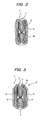
- FIG. 1 shows a lining material used to repair pipelines.
- the lining material 1 is a flexible tubular material comprising a flexible cylindrical resin-absorbing material 3 of a non-woven fabric made of polyester, polypropylene, nylon, acrylic, vinylon, or the like whose exterior surface is covered by a flexible tube 2 of polyethylene, vinyl chloride or the like.
- the resin-absorbing material 3 is impregnated with an uncured liquid thermosetting resin such as unsaturated polyester resin, epoxy resin, or the like.
- the inner surface of the flexible cylindrical resin-absorbing material 3 is covered with a highly hermetic plastic film 3a of polyethylene, vinyl chloride or the like.
- the lining material 1 is folded into the shape of an H and bound with a tape 4 so as to provide a reduced width, as shown in FIG. 2 , and steel belts 6 and 6' as shown in FIGS. 3 to 5 are removably attached to the folded lining material to provide a steel-belted lining material 9 (hereafter abbreviated as belted lining material) in order to facilitate the insertion of the lining material into the pipeline.
- a steel-belted lining material 9 hereafter abbreviated as belted lining material
- the steel belts 6 and 6' are elastic and rigid, impart elasticity and rigidity to the lining material 1, and reinforce the trunk of the lining material 1.
- the belts also partially cover and protect the lining material 1.
- the belts 6 and 6' are composed of a thin steel plate, but it may be composed of strips of steel wire bundled together and covered with rubber and the like.
- An opening 6a is formed respectively in the tip of the steel belts 6 and 6' as shown in FIG. 4 .
- This opening 6a is used to tie a rope or the like for pulling the belted lining assembly 9 when inserting the belted lining assembly 9 into a pipeline.
- the lining material 1 is first folded, as shown in FIG. 2 , so that the cross section is in the shape of an H.
- a tape 4 such as cellophane tape is wound around the width of the lining material 1 at a suitable interval of approximately several tens of centimeters in the lengthwise direction of the lining material 1 to bind the lining material 1. It is acceptable to bind the material with a string or other member instead of tape 4.
- Folding the lining material 1 is not limited to the shape of an H, and any shape is acceptable as long as the material easily extends when made to expand into a cylindrical shape upon application of pressure after inserting the lining material 1 into the pipeline.
- belt loops 5 and 5' for passing the steel belts 6 and 6' therethrough are attached on both sides in the lengthwise direction of the folded lining material 1 at suitable intervals, such as twice the interval of the tape 4.
- the belt loops 5 and 5' serve to guide the steel belt 6 and 6' therethrough with some space maintained and to prevent the steel belts 6 and 6' from shifting significantly from the lining material 1.
- the belt loops 5 and 5' are formed in a strip from a film such as polyethylene and the like, and both ends 5a of the belt loop 5 and 5' are secured by welding or the like to the exterior surface (the exterior surface of tube 2) of the folded lining material 1.
- the steel belts 6 and 6' are attached to each side surface in the lengthwise direction of the lining material 1 so as to sandwich the lining material 1.
- one steel belt 6 is inserted into the belt loops 5 on one side of the lining material 1 and the other steel belt 6' into the belt loops 5' on the other side thereof.
- the ends of each steel belt extend a suitable length L1 (e.g., approximately 30 centimeters) from the end 1a of the lining material 1, and the steel belts 6 and 6' are fixed at the ends by being bound with a strong thread 7.
- a strong thread 8 is also used to wrap and tie the steel belts 6, 6' and the lining material 1 at the section extending a length of L2 (e.g., approximately 30 centimeters) from the end 1a of the lining material 1 in the direction opposite to the tip of the steel belt 6 and 6'. It is acceptable to use other materials such as string instead of the threads 7 and 8. This completes the belted lining assembly 9.
- the belt loops 5 and 5' can be attached to the lining material 1 from the top of the steel belts 6 and 6' after the ends of the steel belts 6, 6' and the end of the lining material 1 have been fixed.
- the belted lining assembly 9 prepared as indicated above is pushed or drawn into the pipeline, as shown in FIG. 6 . If drawn in, the belted lining assembly 9 is tied with a rope or the like to the opening 6a on the ends of the steel belts 6 and 6' and is then pulled.
- FIG. 6 shows the state where the belted lining assembly 9 is inserted into a bent lateral pipe 31 from a main pipe 30 of a pipeline.
- the steel belts 6 and 6' impart elasticity and rigidity to the belted lining assembly 9, and reinforce th trunk.
- the width of the belted lining assembly 9 is narrower than the width of the original lining material 1 because it is folded.
- the section having a length of L1 from the end of the steel belt 6 does not sandwich the lining material, provides enhanced elasticity and flexibility, and easily bends in accordance with the bent sections of the pipeline that are bent at a right angle or close to a right angle, and fulfills the role of guiding subsequent sections.
- the contact resistance of the belted lining assembly 9 is low, the belted lining material 9 can be easily and smoothly inserted, and the time required for lining work can be reduced. Also, since the contact resistance is low and the steel belts 6 and 6' protects the lining material 1, it is possible to prevent stretching and damage to the lining material 1.
- the threads 7 and 8 at the ends of the belted lining assembly 9 are cut, which disconnects the bond between the ends of the steel belts 6 and 6' and the bond between the steel belts and the end of the lining material 1. If the two ends of the steel belts 6 and 6' are pulled, the steel belts 6 and 6' can be slid against the lining material 1 inside the pipeline. This allows the steel belts 6 and 6' to be pulled and extracted from the pipeline and the lining material 1 to be left inside the pipeline.
- the lining material 1 remaining inside the pipeline is made to expand via application of pressure from the inside, such as air pressure or the like.
- the strength of the tape 4 is set so that the tape 4 can be cut with the increased pressure at this point.
- the tape 4 is thus cut by the increased pressure, and the lining material 1 folded and bound by the tape 4 spreads out and expands into a cylindrical shape and is pressed against the inner peripheral surface of the pipeline.
- the lining material 1 is heated by a hot water shower or steam, the thermosetting resin impregnated into the lining material 1 is cured, and the pipeline is lined.
- the lining material can be easily and smoothly inserted into a pipeline with a plurality of locations that, as indicated above, are bent at a right angle or close to a right angle, and the time for lining work can be reduced. Also, stretching and damage can be prevented during insertion of the lining material, thus protecting the quality of the lining material.
- FIGS. 7 , 8a and 8b show another embodiment of a belted lining assembly, denoted by the numerical symbol 19. Portions similar to those of the belted lining material 9 shown in FIGS. 3 through 5 are denoted by the same numerical symbols and are not described.
- one end (tip end) 1a of the lining material 1 as seen in the lengthwise direction (length direction of the pipe) is linked using a rivet 14 or another such coupling implement with one end of another steel belt 10 having elasticity and rigidity in order to guide the lining material 1.
- a hole 10a for fastening a drawing rope 20 is formed in the other end of the steel belt 10.
- the steel belts 6 and 6' sandwiching the lining material 1 extend further than the tip end portion 1a of the lining material 1.
- the tip ends 6b of the steel belts 6 and 6' extend to the substantial center of the steel belt 10, and the steel belts 6, 6' are fixed to the steel belt 10 in the center of the steel belt 10 via rivets 12, 13 or other such coupling implements ( FIG. 8b ).
- the rivets 12, 13 are covered using a plastic tape 11 having a smooth surface in order to prevent the rivets 12, 13 from coming into contact with the inner wall of a pipe and failing to be smoothly drawn in when the belted lining assembly 19 is inserted into a pipe. Since the steel belt 10 and the steel belts 6, 6' are linked by rivets or the like, the linked portions can be prevented from losing elasticity in comparison with coupling using welding or another method.
- the steel belts 6, 6' are bound to the tip end portion of the lining material 1 with a strong thread 8, and the lining material 1 and the steel belts 6, 6' are fixed to each other so as to not separate.
- this type of belted lining material 19 is used as a lining material for a lateral pipe, a flange-like collar is formed at the back end of the lining material 1, and this collar is depicted by the imaginary line 16 in FIG. 7 .
- This type of belted lining assembly 19 is inserted from the tip end into a pipe by being pushed or drawn in, similar to the belted lining assembly 9.
- FIG. 9 shows the manner in which the belted lining assembly 19 is inserted from the main pipe 30 into the bent lateral pipe 31 via a lateral pipe opening 31a.
- the belted lining material 19 is drawn into the lateral pipe 31 via the lateral pipe opening 31a by fastening the drawing rope 20 in the hole 10a of the steel belt 10 and winding up the drawing rope 20 from above ground.
- the belted lining assembly 19 is further drawn in until the tip end of the lining material 1 appears above ground.
- the thread 8 is then cut to undo the link between the steel belts 6, 6' and the lining material 1, and the lining material 1 is cut at the portion 1b so as to be disconnected from the steel belt 10. If the steel belt 10 is pulled, the steel belts 6, 6' can be pulled out of the belt loops 5, 5' and removed from the lining material 1.
- the lining material 1 remaining in the lateral pipe is then subjected to air pressure or the like from the inside and made to expand.
- the tape 4 is cut by the application of pressure, and the folded lining material 1 widens and expands into a tubular shape and comes into pressured contact with the internal peripheral surface of the lateral pipe 31.
- the lining material 1 is heated by hot water, steam, or another such heating medium, and the thermosetting resin impregnated in the lining material 1 is cured, thus lining the lateral pipe.
- This type of belted lining assembly 19, as compared with the belted lining assembly 9, can be readily inserted with minimal obstruction into a lateral pipe having a large number of sections bent at a right angle or approximately a right angle. This is because the lining material 1 is directly fixed via the coupling implement 14 to the steel belt 10, and the lining material 1 can be directly pulled via the steel belt 10.
- the drawing in or pushing in of the entire lining material is also more reliable because the steel belts 6, 6' attached at both sides of the lining material are linked to the steel belt 10 for guiding the lining material 1.
- the lining material can be readily and smoothly inserted into a pipe having a large number of sections bent at a right angle or approximately a right angle, and damage to the lining material can be prevented because the lining material is protected by the steel belts 6, 6' while being inserted into the pipe.
- a hose for guiding hot water, steam, or another such heating medium for curing the thermosetting resin impregnated in the lining material can be provided in the interior of the belted lining assembly 9 or 19. An example of this is shown in FIGS. 10 and 11 .
- a belted lining material houses a hose 40 of a substantially equal length to the lining assembly 19, as shown in FIGS. 10 and 11 .
- the lining material 1 is left in the pipe while the steel belts 6, 6' are pulled out of the pipe, and pressure is applied to the lining material 1 to bring it into pressured contact with the internal peripheral surface of the pipe; hot water, steam, or another such heating medium is supplied from the end of the hose 40 nearer the main pipe. Since the main pipe 30 is plugged so that water may not flow, the heating medium discharged from the tip end of the hose 40 accumulates up to the lateral pipe 31. This causes the lining material 1 in the lateral pipe 31 to be heated to cure the thermosetting resin impregnated in the lining material 1 and line the lateral pipe 31.
- the hose 40 may be provided with a large number of holes, and the heating medium may be blown out of these holes as a shower or mist onto the internal peripheral surface of the lining material 1 in pressure contact against the pipe internal peripheral surface in order to cure the lining material 1.
- the heating medium is hot water
- the hot water can also be circulated.
- an elastic and rigid member for example, steel
- the hose 40 is moved up and down to rub against the internal peripheral surface of the lining material and stretch out the wrinkles that have formed in the resin in the lining material. This makes uniform lining in the pipe possible even when the pipe is bent.
- the steel belts 6 and 6' can be attached across the entire length of the lining material 1, or can be attached across a portion of the entire length of the lining material 1.
- two steel belts 6 and 6' are attached so as to sandwich the lining material 1, but it is acceptable to attach only one belt to one side of the lining material 1. It is also acceptable to attach three or more belts so as to enclose the lining material 1.
- another elastic and rigid belt member composed of a non-steel metal, plastic, or other material can be attached to the lining material 1.
- the lining material of the present invention can be used not only as a lining for a communications pipe, gas pipe, sewer pipe, water pipe, electrical pipe, or other subterranean pipeline, but also as a lining for a communications pipe, gas pipe, sewer pipe, water pipe, electrical pipe, or other pipeline inside apartment buildings, office buildings, and other buildings.
Landscapes
- Engineering & Computer Science (AREA)
- General Engineering & Computer Science (AREA)
- Mechanical Engineering (AREA)
- Lining Or Joining Of Plastics Or The Like (AREA)
Claims (10)
- Rohrförmige Auskleidungsanordnung zum Einsetzen in eine zu reparierende Rohrleitung (31), umfassend ein flexibles, rohrförmiges Auskleidungsmaterial (1), das mit einem wärmehärtbaren Harz imprägniert ist, und ein erstes und zweites elastisches und steifes Streifenelement (6, 6'), die als aus Stahl oder einem anderen Metall als Stahl gebildete Bänder ausgebildet sind, wobei das Auskleidungsmaterial (1) so gefaltet ist, dass es eine verminderte Breite aufweist, und das erste Streifenelement (6) lösbar an einer Seite des gefalteten Auskleidungsmaterials und das zweite Streifenelement (6') an dessen anderer Seite lösbar angebracht ist, um das Auskleidungsmaterial dazwischen einzulegen und zu verstärken, und wobei die ersten und zweiten Streifenelemente (6, 6') lösbar am Auskleidungsmaterial (1) angebracht sind, so dass sie vom Auskleidungsmaterial lösbar sind, nachdem die rohrförmige Auskleidungsanordnung in die Rohrleitung (31) eingesetzt wurde, während das Auskleidungsmaterial in der Rohrleitung verbleibt.
- Rohrförmige Auskleidungsanordnung nach Anspruch 1, wobei das erste und das zweite Streifenelement (6, 6') Stahlbänder sind.
- Rohrförmige Auskleidungsanordnung nach Anspruch 1 oder 2, wobei die Streifenelemente (6, 6') entlang der gesamten Länge des Auskleidungsmaterials (1) angebracht sind.
- Rohrförmige Auskleidungsanordnung nach einem der Ansprüche 1 bis 3, wobei die Streifenelemente (6, 6') entlang einem Teil der gesamten Länge des Auskleidungsmaterials (1) angebracht sind.
- Rohrförmige Auskleidungsanordnung nach einem der Ansprüche 1 bis 4, wobei das erste und zweite Streifenelement (6, 6') am Auskleidungsmaterial (1) so angebracht sind, dass die Spitzen der Streifenelemente (6, 6') von der Spitze (1a) des Auskleidungsmaterials (1) vorstehen.
- Rohrförmige Auskleidungsanordnung nach einem der Ansprüche 1 bis 5, wobei ein drittes elastisches und steifes Streifenelement (10), das als aus Stahl oder einem anderen Metall als Stahl gebildetes Band ausgebildet ist, fest an der Spitze (1a) des Auskleidungsmaterials (1) angebracht ist, um das Auskleidungsmaterial (1) zu führen.
- Rohrförmige Auskleidungsanordnung nach Anspruch 6, wobei sich das erste und zweite Streifenelement (6, 6') im Wesentlichen bis zur Mitte des dritten Streifenelementes (10) hin erstrecken und daran befestigt sind.
- Rohrförmige Auskleidungsanordnung nach Anspruch 5 oder 6, wobei das dritte Streifenelement (10) ein Stahlband ist.
- Rohrförmige Auskleidungsanordnung nach einem der Ansprüche 1 bis 8, wobei das Auskleidungsmaterial (1) einen Schlauch (40) aufnimmt, um darin ein Heizmedium, welches das darin imprägnierte, wärmehärtbare Harz aushärtet, zu führen.
- Verfahren zum Auskleiden einer Rohrleitung unter Verwendung einer rohrförmigen Auskleidungsanordnung, umfassend ein flexibles, rohrförmiges Auskleidungsmaterial (1), das mit einem wärmehärtbaren Harz imprägniert ist, und ein erstes und zweites Streifenelement (6, 6') nach einem der Ansprüche 1 bis 9, umfassend die Schritte:Ziehen oder Einsetzen der rohrförmigen Auskleidungsanordnung in eine zu reparierende Rohrleitung (31);Lösen und Herausziehen des ersten und zweiten Streifenelementes (6, 6') aus dem Auskleidungsmaterial (1), während das Auskleidungsmaterial (1) gleichzeitig in der Rohrleitung (31) verbleibt, undBeaufschlagen des Auskleidungsmaterials (1) mit Druck, um dessen Expansion gegen eine Innenumfangsfläche der Rohrleitung (31) zu bewirken, und Erwärmen des Auskleidungsmaterials (1), um das Aushärten des wärmehärtbaren Harzes darin zu bewirken.
Priority Applications (2)
| Application Number | Priority Date | Filing Date | Title |
|---|---|---|---|
| AT08155603T ATE552459T1 (de) | 2008-05-02 | 2008-05-02 | Auskleidungsmaterial und verfahren zur rohrleitungsauskleidung |
| EP08155603A EP2113708B1 (de) | 2008-05-02 | 2008-05-02 | Auskleidungsmaterial und Verfahren zur Rohrleitungsauskleidung |
Applications Claiming Priority (1)
| Application Number | Priority Date | Filing Date | Title |
|---|---|---|---|
| EP08155603A EP2113708B1 (de) | 2008-05-02 | 2008-05-02 | Auskleidungsmaterial und Verfahren zur Rohrleitungsauskleidung |
Publications (2)
| Publication Number | Publication Date |
|---|---|
| EP2113708A1 EP2113708A1 (de) | 2009-11-04 |
| EP2113708B1 true EP2113708B1 (de) | 2012-04-04 |
Family
ID=40044109
Family Applications (1)
| Application Number | Title | Priority Date | Filing Date |
|---|---|---|---|
| EP08155603A Not-in-force EP2113708B1 (de) | 2008-05-02 | 2008-05-02 | Auskleidungsmaterial und Verfahren zur Rohrleitungsauskleidung |
Country Status (2)
| Country | Link |
|---|---|
| EP (1) | EP2113708B1 (de) |
| AT (1) | ATE552459T1 (de) |
Families Citing this family (3)
| Publication number | Priority date | Publication date | Assignee | Title |
|---|---|---|---|---|
| US20110236138A1 (en) * | 2010-03-24 | 2011-09-29 | Cosban William C | Method for repairing and reinforcing underground pipes |
| GB201614608D0 (en) * | 2016-08-29 | 2016-10-12 | Ecosse Global Uk Ltd | Tubular repair system and method |
| AU2022203404A1 (en) * | 2021-05-19 | 2022-12-08 | Repiper Ab | Liner Arrangement For Inserting in a Pipe Structure, and Method For Relining a Pipe Structure |
Family Cites Families (7)
| Publication number | Priority date | Publication date | Assignee | Title |
|---|---|---|---|---|
| NO140682C (no) * | 1975-07-02 | 1979-10-17 | Norske Remfabrik As | Tynnvegget slange av elastisk materiale, fortrinnsvis gummi, til innvendig foring av vannledninger, saerlig avloepsroer av betong |
| FR2503622A1 (fr) * | 1981-04-13 | 1982-10-15 | Laurent Jacques | Procede pour chemiser interieurement des canalisations et tube pour sa mise en oeuvre |
| GB8712954D0 (en) * | 1987-06-03 | 1987-07-08 | Hutton F A | Apparatus for lining passages |
| GB8714449D0 (en) * | 1987-06-19 | 1987-07-22 | Ici Plc | Liner for tubular form |
| US5546992A (en) * | 1994-01-18 | 1996-08-20 | Insituform (Netherlands) B.V. | Dual containment pipe rehabilitation system |
| NL1018733C1 (nl) * | 2001-08-09 | 2003-02-17 | Ina Acquisition Corp | Werkwijze voor het aanbrengen van een mantelbuis. |
| US7849883B2 (en) * | 2005-05-02 | 2010-12-14 | Nuflow Technologies 2000 Inc. | Liner assembly for pipeline repair and methods of installing same |
-
2008
- 2008-05-02 AT AT08155603T patent/ATE552459T1/de active
- 2008-05-02 EP EP08155603A patent/EP2113708B1/de not_active Not-in-force
Also Published As
| Publication number | Publication date |
|---|---|
| ATE552459T1 (de) | 2012-04-15 |
| EP2113708A1 (de) | 2009-11-04 |
Similar Documents
| Publication | Publication Date | Title |
|---|---|---|
| US7708033B2 (en) | Lining material and pipeline lining method | |
| US20100282351A1 (en) | Pipe-lining material and pipeline lining method | |
| JP2736368B2 (ja) | 管路の内張り材及び管路の内張り方法 | |
| EP1034394B1 (de) | Verfahren und system zur örtlichen reparatur von rohren und rohrleitungen | |
| KR100557753B1 (ko) | 지관라이닝재 및 지관라이닝 공법 | |
| US8025461B2 (en) | Lining material and pipeline lining method | |
| US9200742B2 (en) | Lateral pipe-lining method | |
| EP2113708B1 (de) | Auskleidungsmaterial und Verfahren zur Rohrleitungsauskleidung | |
| AU2021102901A4 (en) | A bladder assembly and method | |
| US20090183794A1 (en) | Lateral pipe lining material and lateral pipe lining method | |
| JP4425684B2 (ja) | ケーブル布設済み保護管補修方法 | |
| JP5607099B2 (ja) | ライニング材及び管路ライニング工法 | |
| KR20080092109A (ko) | 라이닝재 및 관로 라이닝 공법 | |
| JP2012254637A (ja) | ライニング材及び管路ライニング工法 | |
| JP4898339B2 (ja) | 既設管路のライニング工法 | |
| JP4573246B2 (ja) | 地中埋設管補修方法 | |
| JP2008023825A (ja) | 屈曲管路のホース材引き込みライニング工法 | |
| US20150354743A1 (en) | Arrangement and method for lining pipes | |
| JP3826384B2 (ja) | 配管補修方法 | |
| JP4560370B2 (ja) | 枝管ライニング材及び枝管ライニング工法 | |
| AU737147B2 (en) | System for the formed-in-situ localised repair of pipes and conduits | |
| JP2006071004A (ja) | 枝管ライニング材及び枝管ライニング工法 | |
| JP2004034369A (ja) | 管路内面更生材 | |
| JP2003291217A (ja) | 管路内面更生材 | |
| JP2002307557A (ja) | 管路内面更生材 |
Legal Events
| Date | Code | Title | Description |
|---|---|---|---|
| PUAI | Public reference made under article 153(3) epc to a published international application that has entered the european phase |
Free format text: ORIGINAL CODE: 0009012 |
|
| 17P | Request for examination filed |
Effective date: 20090130 |
|
| AK | Designated contracting states |
Kind code of ref document: A1 Designated state(s): AT BE BG CH CY CZ DE DK EE ES FI FR GB GR HR HU IE IS IT LI LT LU LV MC MT NL NO PL PT RO SE SI SK TR |
|
| AX | Request for extension of the european patent |
Extension state: AL BA MK RS |
|
| AKX | Designation fees paid |
Designated state(s): AT BE BG CH CY CZ DE DK EE ES FI FR GB GR HR HU IE IS IT LI LT LU LV MC MT NL NO PL PT RO SE SI SK TR |
|
| GRAP | Despatch of communication of intention to grant a patent |
Free format text: ORIGINAL CODE: EPIDOSNIGR1 |
|
| GRAS | Grant fee paid |
Free format text: ORIGINAL CODE: EPIDOSNIGR3 |
|
| GRAA | (expected) grant |
Free format text: ORIGINAL CODE: 0009210 |
|
| RTI1 | Title (correction) |
Free format text: LINING MATERIAL AND PIPELINE LINING METHOD |
|
| AK | Designated contracting states |
Kind code of ref document: B1 Designated state(s): AT BE BG CH CY CZ DE DK EE ES FI FR GB GR HR HU IE IS IT LI LT LU LV MC MT NL NO PL PT RO SE SI SK TR |
|
| REG | Reference to a national code |
Ref country code: GB Ref legal event code: FG4D |
|
| REG | Reference to a national code |
Ref country code: CH Ref legal event code: EP |
|
| REG | Reference to a national code |
Ref country code: AT Ref legal event code: REF Ref document number: 552459 Country of ref document: AT Kind code of ref document: T Effective date: 20120415 |
|
| REG | Reference to a national code |
Ref country code: IE Ref legal event code: FG4D |
|
| REG | Reference to a national code |
Ref country code: DE Ref legal event code: R096 Ref document number: 602008014574 Country of ref document: DE Effective date: 20120531 |
|
| REG | Reference to a national code |
Ref country code: NL Ref legal event code: VDEP Effective date: 20120404 |
|
| PGFP | Annual fee paid to national office [announced via postgrant information from national office to epo] |
Ref country code: DE Payment date: 20120508 Year of fee payment: 5 |
|
| PGFP | Annual fee paid to national office [announced via postgrant information from national office to epo] |
Ref country code: GB Payment date: 20120522 Year of fee payment: 5 Ref country code: FR Payment date: 20120608 Year of fee payment: 5 |
|
| REG | Reference to a national code |
Ref country code: AT Ref legal event code: MK05 Ref document number: 552459 Country of ref document: AT Kind code of ref document: T Effective date: 20120404 |
|
| LTIE | Lt: invalidation of european patent or patent extension |
Effective date: 20120404 |
|
| PG25 | Lapsed in a contracting state [announced via postgrant information from national office to epo] |
Ref country code: NO Free format text: LAPSE BECAUSE OF FAILURE TO SUBMIT A TRANSLATION OF THE DESCRIPTION OR TO PAY THE FEE WITHIN THE PRESCRIBED TIME-LIMIT Effective date: 20120704 Ref country code: IS Free format text: LAPSE BECAUSE OF FAILURE TO SUBMIT A TRANSLATION OF THE DESCRIPTION OR TO PAY THE FEE WITHIN THE PRESCRIBED TIME-LIMIT Effective date: 20120804 Ref country code: CY Free format text: LAPSE BECAUSE OF FAILURE TO SUBMIT A TRANSLATION OF THE DESCRIPTION OR TO PAY THE FEE WITHIN THE PRESCRIBED TIME-LIMIT Effective date: 20120404 Ref country code: SE Free format text: LAPSE BECAUSE OF FAILURE TO SUBMIT A TRANSLATION OF THE DESCRIPTION OR TO PAY THE FEE WITHIN THE PRESCRIBED TIME-LIMIT Effective date: 20120404 Ref country code: LT Free format text: LAPSE BECAUSE OF FAILURE TO SUBMIT A TRANSLATION OF THE DESCRIPTION OR TO PAY THE FEE WITHIN THE PRESCRIBED TIME-LIMIT Effective date: 20120404 Ref country code: SI Free format text: LAPSE BECAUSE OF FAILURE TO SUBMIT A TRANSLATION OF THE DESCRIPTION OR TO PAY THE FEE WITHIN THE PRESCRIBED TIME-LIMIT Effective date: 20120404 Ref country code: PL Free format text: LAPSE BECAUSE OF FAILURE TO SUBMIT A TRANSLATION OF THE DESCRIPTION OR TO PAY THE FEE WITHIN THE PRESCRIBED TIME-LIMIT Effective date: 20120404 Ref country code: FI Free format text: LAPSE BECAUSE OF FAILURE TO SUBMIT A TRANSLATION OF THE DESCRIPTION OR TO PAY THE FEE WITHIN THE PRESCRIBED TIME-LIMIT Effective date: 20120404 |
|
| PG25 | Lapsed in a contracting state [announced via postgrant information from national office to epo] |
Ref country code: PT Free format text: LAPSE BECAUSE OF FAILURE TO SUBMIT A TRANSLATION OF THE DESCRIPTION OR TO PAY THE FEE WITHIN THE PRESCRIBED TIME-LIMIT Effective date: 20120806 Ref country code: HR Free format text: LAPSE BECAUSE OF FAILURE TO SUBMIT A TRANSLATION OF THE DESCRIPTION OR TO PAY THE FEE WITHIN THE PRESCRIBED TIME-LIMIT Effective date: 20120404 Ref country code: LV Free format text: LAPSE BECAUSE OF FAILURE TO SUBMIT A TRANSLATION OF THE DESCRIPTION OR TO PAY THE FEE WITHIN THE PRESCRIBED TIME-LIMIT Effective date: 20120404 Ref country code: GR Free format text: LAPSE BECAUSE OF FAILURE TO SUBMIT A TRANSLATION OF THE DESCRIPTION OR TO PAY THE FEE WITHIN THE PRESCRIBED TIME-LIMIT Effective date: 20120705 |
|
| PG25 | Lapsed in a contracting state [announced via postgrant information from national office to epo] |
Ref country code: BE Free format text: LAPSE BECAUSE OF FAILURE TO SUBMIT A TRANSLATION OF THE DESCRIPTION OR TO PAY THE FEE WITHIN THE PRESCRIBED TIME-LIMIT Effective date: 20120404 Ref country code: MC Free format text: LAPSE BECAUSE OF NON-PAYMENT OF DUE FEES Effective date: 20120531 |
|
| REG | Reference to a national code |
Ref country code: CH Ref legal event code: PL |
|
| PG25 | Lapsed in a contracting state [announced via postgrant information from national office to epo] |
Ref country code: CH Free format text: LAPSE BECAUSE OF NON-PAYMENT OF DUE FEES Effective date: 20120531 Ref country code: CZ Free format text: LAPSE BECAUSE OF FAILURE TO SUBMIT A TRANSLATION OF THE DESCRIPTION OR TO PAY THE FEE WITHIN THE PRESCRIBED TIME-LIMIT Effective date: 20120404 Ref country code: LI Free format text: LAPSE BECAUSE OF NON-PAYMENT OF DUE FEES Effective date: 20120531 Ref country code: AT Free format text: LAPSE BECAUSE OF FAILURE TO SUBMIT A TRANSLATION OF THE DESCRIPTION OR TO PAY THE FEE WITHIN THE PRESCRIBED TIME-LIMIT Effective date: 20120404 Ref country code: RO Free format text: LAPSE BECAUSE OF FAILURE TO SUBMIT A TRANSLATION OF THE DESCRIPTION OR TO PAY THE FEE WITHIN THE PRESCRIBED TIME-LIMIT Effective date: 20120404 Ref country code: SK Free format text: LAPSE BECAUSE OF FAILURE TO SUBMIT A TRANSLATION OF THE DESCRIPTION OR TO PAY THE FEE WITHIN THE PRESCRIBED TIME-LIMIT Effective date: 20120404 Ref country code: EE Free format text: LAPSE BECAUSE OF FAILURE TO SUBMIT A TRANSLATION OF THE DESCRIPTION OR TO PAY THE FEE WITHIN THE PRESCRIBED TIME-LIMIT Effective date: 20120404 Ref country code: NL Free format text: LAPSE BECAUSE OF FAILURE TO SUBMIT A TRANSLATION OF THE DESCRIPTION OR TO PAY THE FEE WITHIN THE PRESCRIBED TIME-LIMIT Effective date: 20120404 Ref country code: DK Free format text: LAPSE BECAUSE OF FAILURE TO SUBMIT A TRANSLATION OF THE DESCRIPTION OR TO PAY THE FEE WITHIN THE PRESCRIBED TIME-LIMIT Effective date: 20120404 |
|
| PLBE | No opposition filed within time limit |
Free format text: ORIGINAL CODE: 0009261 |
|
| STAA | Information on the status of an ep patent application or granted ep patent |
Free format text: STATUS: NO OPPOSITION FILED WITHIN TIME LIMIT |
|
| REG | Reference to a national code |
Ref country code: IE Ref legal event code: MM4A |
|
| PG25 | Lapsed in a contracting state [announced via postgrant information from national office to epo] |
Ref country code: IT Free format text: LAPSE BECAUSE OF FAILURE TO SUBMIT A TRANSLATION OF THE DESCRIPTION OR TO PAY THE FEE WITHIN THE PRESCRIBED TIME-LIMIT Effective date: 20120404 |
|
| 26N | No opposition filed |
Effective date: 20130107 |
|
| PG25 | Lapsed in a contracting state [announced via postgrant information from national office to epo] |
Ref country code: ES Free format text: LAPSE BECAUSE OF FAILURE TO SUBMIT A TRANSLATION OF THE DESCRIPTION OR TO PAY THE FEE WITHIN THE PRESCRIBED TIME-LIMIT Effective date: 20120715 Ref country code: IE Free format text: LAPSE BECAUSE OF NON-PAYMENT OF DUE FEES Effective date: 20120502 |
|
| REG | Reference to a national code |
Ref country code: DE Ref legal event code: R097 Ref document number: 602008014574 Country of ref document: DE Effective date: 20130107 |
|
| PG25 | Lapsed in a contracting state [announced via postgrant information from national office to epo] |
Ref country code: MT Free format text: LAPSE BECAUSE OF FAILURE TO SUBMIT A TRANSLATION OF THE DESCRIPTION OR TO PAY THE FEE WITHIN THE PRESCRIBED TIME-LIMIT Effective date: 20120404 Ref country code: BG Free format text: LAPSE BECAUSE OF FAILURE TO SUBMIT A TRANSLATION OF THE DESCRIPTION OR TO PAY THE FEE WITHIN THE PRESCRIBED TIME-LIMIT Effective date: 20120704 |
|
| GBPC | Gb: european patent ceased through non-payment of renewal fee |
Effective date: 20130502 |
|
| PG25 | Lapsed in a contracting state [announced via postgrant information from national office to epo] |
Ref country code: DE Free format text: LAPSE BECAUSE OF NON-PAYMENT OF DUE FEES Effective date: 20131203 |
|
| REG | Reference to a national code |
Ref country code: FR Ref legal event code: ST Effective date: 20140131 |
|
| REG | Reference to a national code |
Ref country code: DE Ref legal event code: R119 Ref document number: 602008014574 Country of ref document: DE Effective date: 20131203 |
|
| PG25 | Lapsed in a contracting state [announced via postgrant information from national office to epo] |
Ref country code: GB Free format text: LAPSE BECAUSE OF NON-PAYMENT OF DUE FEES Effective date: 20130502 Ref country code: TR Free format text: LAPSE BECAUSE OF FAILURE TO SUBMIT A TRANSLATION OF THE DESCRIPTION OR TO PAY THE FEE WITHIN THE PRESCRIBED TIME-LIMIT Effective date: 20120404 |
|
| PG25 | Lapsed in a contracting state [announced via postgrant information from national office to epo] |
Ref country code: FR Free format text: LAPSE BECAUSE OF NON-PAYMENT OF DUE FEES Effective date: 20130531 Ref country code: LU Free format text: LAPSE BECAUSE OF NON-PAYMENT OF DUE FEES Effective date: 20120502 |
|
| PG25 | Lapsed in a contracting state [announced via postgrant information from national office to epo] |
Ref country code: HU Free format text: LAPSE BECAUSE OF FAILURE TO SUBMIT A TRANSLATION OF THE DESCRIPTION OR TO PAY THE FEE WITHIN THE PRESCRIBED TIME-LIMIT Effective date: 20080502 |