EP2113476B1 - Sicherheitsvorrichtung für Verladerampen oder Entladerampen - Google Patents
Sicherheitsvorrichtung für Verladerampen oder Entladerampen Download PDFInfo
- Publication number
- EP2113476B1 EP2113476B1 EP09005609A EP09005609A EP2113476B1 EP 2113476 B1 EP2113476 B1 EP 2113476B1 EP 09005609 A EP09005609 A EP 09005609A EP 09005609 A EP09005609 A EP 09005609A EP 2113476 B1 EP2113476 B1 EP 2113476B1
- Authority
- EP
- European Patent Office
- Prior art keywords
- analysis system
- information
- locating device
- vehicle
- support
- Prior art date
- Legal status (The legal status is an assumption and is not a legal conclusion. Google has not performed a legal analysis and makes no representation as to the accuracy of the status listed.)
- Not-in-force
Links
- 238000004458 analytical method Methods 0.000 claims abstract description 98
- 238000010200 validation analysis Methods 0.000 claims abstract description 7
- 230000033001 locomotion Effects 0.000 claims description 20
- 230000000694 effects Effects 0.000 claims description 2
- 230000011664 signaling Effects 0.000 description 10
- 238000006073 displacement reaction Methods 0.000 description 5
- 238000001514 detection method Methods 0.000 description 4
- 238000009434 installation Methods 0.000 description 4
- 230000001939 inductive effect Effects 0.000 description 2
- 239000000463 material Substances 0.000 description 2
- 238000000034 method Methods 0.000 description 2
- 230000000717 retained effect Effects 0.000 description 2
- 230000005236 sound signal Effects 0.000 description 2
- 230000001960 triggered effect Effects 0.000 description 2
- 230000004913 activation Effects 0.000 description 1
- 230000000740 bleeding effect Effects 0.000 description 1
- 230000000903 blocking effect Effects 0.000 description 1
- 239000000969 carrier Substances 0.000 description 1
- 230000000763 evoking effect Effects 0.000 description 1
- 238000005007 materials handling Methods 0.000 description 1
- 238000009877 rendering Methods 0.000 description 1
- 230000035945 sensitivity Effects 0.000 description 1
- 125000006850 spacer group Chemical group 0.000 description 1
- 238000012795 verification Methods 0.000 description 1
Images

Classifications
-
- B—PERFORMING OPERATIONS; TRANSPORTING
- B65—CONVEYING; PACKING; STORING; HANDLING THIN OR FILAMENTARY MATERIAL
- B65G—TRANSPORT OR STORAGE DEVICES, e.g. CONVEYORS FOR LOADING OR TIPPING, SHOP CONVEYOR SYSTEMS OR PNEUMATIC TUBE CONVEYORS
- B65G69/00—Auxiliary measures taken, or devices used, in connection with loading or unloading
- B65G69/003—Restraining movement of a vehicle at a loading station using means not being part of the vehicle
- B65G69/005—Restraining movement of a vehicle at a loading station using means not being part of the vehicle the means engaging at least one wheel of the vehicle
Definitions
- the present invention relates to loading docks or unloading goods of the type of those in which the transhipment of packages between a warehouse and transport vehicles, whether to bring the packages in the warehouse is carried out or to take them from there to deliver them elsewhere, it concerns a safety equipment for platforms according to the preamble of claim 1 and use of equipment according to the preamble of claim 8. It is essentially intended to equip such docks of automatic means of information to improve the working conditions at their approach, particularly from the point of view of safety, that of the handlers and other operators such as the goods transported.
- the invention involves shims that dock staff is accustomed to use to block the wheels of vehicles and thus immobilize the latter in a proper position relative to the dock.
- other tools can be used for the same purposes, inasmuch as it is considered most important that they have to be placed in a given position to signal that loading or unloading operations can be undertaken.
- the equipment according to the preamble of claim 1 is described in the document " A loading bay loading, "MATERIALS HANDLING NEWS, NEXUS MEDIA COMMUNICATIONS, SWANLEY, KENT, GB, No. 558, June 1, 2004 .
- a vehicle access path to the platform of a series of radio-identification tags succeeding each other along this path and to verify, by appropriate means associated with said platform, if a device for locating readers of these labels is or is not positioned in a predetermined position respecting a predefined direction relative to the sequence of tags along the access path to the dock.
- the information resulting from this verification is used in particular to warn the handlers that a vehicle arriving at the dock is in a situation authorizing loading or unloading operations.
- the tracking device is advantageously made in the form of a wedge blocking the wheels of the vehicle or any other means to immobilize the latter dock.
- the invention therefore has the advantage of using wireless telecommunication techniques to transmit the information necessary for verifying a correct position of the tracking device, as well as for possibly transmitting a signal. signal to the handlers allowing them to proceed with the loading or unloading of the vehicles brought to the wharf.
- These techniques advantageously pass through the use of RFID chips (for "radio-frequency identification" in English), hence including a great convenience of setting up the equipment according to the invention in existing platforms or groups of platforms.
- the different labels can be individually integrated in a simple bleeding made in the ground, the readers being fixed on the base of usual tools confirming the immobilization of the freight trucks.
- the tags may be embedded in signal strips that are then glued to the ground. As a non-limiting example in this case, they can be glued to the underside, intended to be bonded to the ground, of such a signaling strip.
- each dock of a warehouse or any other set of loading and unloading of goods to and from vehicles brought to the dock thus comprises, according to the invention, radio-identification tags arranged in series along an access road to the platform for vehicles for transporting goods to be loaded or unloaded, said labels being, on the one hand, carrying and transmitting identification information characteristic of the order of succession of the labels in series, and, on the other hand, when the loading and unloading assembly comprises several platforms, carrying and transmitting identification information characteristic of the platform along the path to which the labels are placed in the platform. series of platforms.
- a mobile tracking device In association with these labels, it is planned to use, for each vehicle parked at the dock, a mobile tracking device to be placed in a given position relative to this vehicle, position in which two radio transmitters radio transmitters placed on this locating device pick up the signals emitted by at least two different labels of the series, to send back to the analysis system associated with the quay or to the set of quays concerned signals carrying the identification information specific to each read tags and reader attribute information distinguishing the two readers from each other.
- computer processing means are programmed to check, based on all of the tag information and reader information, whether the tracking device has been correctly placed in its determined position relative to the platform, respecting a predefined direction between the two readers from the nearest to the farthest relative to the platform in the sequence of the labels in the series.
- the tracking device is a shim intended to be placed against a wheel of a vehicle parked at the dock to complete the immobilization of it.
- a shim of generally prismatic shape, therefore advantageously has, as close as possible to its face intended to rest on the ground, two separate radiofrequency readers as far apart as possible from each other than the geometry and the dimension of the wedge, the two radiofrequency readers being advantageously distributed on an alignment parallel to the orientation of the radio-identification tags arranged in series along a path to the platform.
- the invention provides that these two readers are able to receive the information from all the tags which are placed in their vicinity, and that the analysis system implements discrimination algorithms of a type otherwise known per se in the RFID devices so that the analysis system retains, for each of the readers, only the information issued by one and only one label.
- the analysis system will advantageously retain the information transmitted by the label that is closest to each reader, or, if the reader is located at an equal distance from two consecutive tags, will not retain typically information from the label closest to the wharf.
- the invention provides that, as long as no vehicle is parked at the dock, the shim is placed on a suitable support disposed on the platform, and that this support is equipped with a detector connected by telecommunication means, which may be wireless telecommunications means, the analysis system for sending therein information of presence or absence of said hold.
- this support is connected to a power supply device for recharging power including the radiofrequency transmitter of each of the readers placed on the hold, so that they can reliably, on the one hand, transmit a signal radio frequency activation and interrogation of radio-identification tags placed along the access path to the platform, and, on the other hand, transmit to the analysis system the information sent back by these radiofrequency tags.
- the wedge advantageously comprises means for detecting the presence of a tire of a vehicle in its vicinity, as well as means for transmitting, towards the system of analysis, information of presence of such a tire.
- the means for detecting the presence of a tire of a vehicle near the hold may comprise a closed inductive loop when the shim is disposed against said tire and open in the opposite case, and associated with an electronic contact whose opening or closing information is transmitted by wireless telecommunication means to the analysis system.
- the wedge In the absence of a vehicle parked at the dock, the wedge is arranged on its support, which then returns to the analysis system information of presence of this hold.
- the analysis system performs wedge matching with the hold support.
- the invention provides for the hold to carry its own identification information, for example but not exclusively by means of a radio identification label, and for this identification information to be read by appropriate means equipping the hold support (by way of non-limiting example a radio-identification reader), as well as by the analysis system.
- the pairing is then achieved by the association, by the analysis system, of the identification information carried by the hold to an identification information of the hold support (for example a sequence number in a set of docks).
- an identification information of the hold support for example a sequence number in a set of docks.
- the shim When a vehicle is docked for a loading and / or unloading operation, the shim is removed from its support to be placed against a wheel of the vehicle and ensure a total immobilization of the latter so that the loading operations and / or unloading can be performed by the wharf operators without risk that the vehicle moves relative to the wharf during these operations, which would compromise the safety of people and goods.
- the invention provides that, once the hold is removed from its support, the bilge presence detector This is equipped with sends information of absence of the hold to the analysis system associated with the dock.
- the invention then provides that the different readers and detectors placed on the hold refer to the analysis system associated with the platform, on the one hand, the information received from the radiofrequency identification tags placed in the vicinity of the hold, and, on the other hand, information for detecting or not the presence of a tire of a vehicle in the vicinity of said hold.
- the invention provides that the platform is also equipped with signaling means indicating, after a predefined period of time, for example representative of the average time required to place the wedge against a vehicle wheel, if, on the one hand, the analysis system actually received the different information transmitted by the radiofrequency readers and the tire presence detector, and if, on the other hand, this information effectively indicate that the hold is correctly positioned both in the vicinity of a tire of the vehicle and in the predetermined direction previously indicated in relation to the sequence of tags along the path to the wharf.
- signaling means indicating, after a predefined period of time, for example representative of the average time required to place the wedge against a vehicle wheel, if, on the one hand, the analysis system actually received the different information transmitted by the radiofrequency readers and the tire presence detector, and if, on the other hand, this information effectively indicate that the hold is correctly positioned both in the vicinity of a tire of the vehicle and in the predetermined direction previously indicated in relation to the sequence of tags along the path to the wharf.
- these signaling means may consist of a different color light display depending on whether the information received by the analysis system indicates whether or not the shim has been arranged in the predetermined direction and in the vicinity of the tire. of a vehicle, for example a green light when the hold has been correctly arranged, and a red light in the opposite case, possibly associated with a warning sound signal in the latter case.
- the invention provides that, once the positioning information of the hold received and validated by the analysis system (detection of the presence of a tire of the vehicle in the immediate vicinity of the hold , predetermined direction of placement of the hold with regard to the succession of radio-identification tags along the path), the validation undertaken by the latter ceases.
- the analysis system stops processing the information received from the radiofrequency reader and tire presence detector, until the hold is at new moved.
- the invention provides that the wedge transmits at regular time intervals (as a non-limiting example at intervals of a few seconds) all or part of its positioning information to the analysis system. for example the information it receives from radio frequency tags arranged along the access path to the wharf.
- the invention provides that the validation information of the position of the hold relative to the vehicle, as well as, if necessary, any information of inadvertent displacement of this hold during the handling operations can be communicated to the staff operating on the wharf.
- the wedge is also advantageously provided with a detector, for example of the accelerometer type, able to send to the analysis system a movement information of said wedge.
- the invention provides that, once this signal has been received and the recorded movement has an amplitude greater than a previously fixed threshold, the analysis system verifies the tire presence detection information. If, after a predetermined duration, a presence information of a tire of a vehicle has not been received by the analysis system, the invention then provides that the analysis system controls, after a previously defined duration, the signaling, on the platform, of information representative of the return or not of the hold on its support, on the basis of the presence or absence of information of the hold transmitted to said analysis system by the detector placed on the support thereof.
- the invention provides that the analysis system controls, after a period of time previously defined, the display, on the dock, a representative information the return or not of said shim on the support to which it was previously matched.
- the invention also provides that the analysis system controls the display means to signal an error in the case where a wedge is unduly replaced, after use, on a support different from that with which it was matched whereas, in at the same time, the wedge paired with this support is in use.
- the invention also provides for preventing, in this case, any new pairing of the shim replaced with the support whose shim is in use.
- the invention provides, according to different embodiments, that an analysis system is associated with each platform, or that a central analysis and supervision system manages all the information sent and received by all the identification labels placed along the various access roads to the various platforms, as well as by all radio frequency readers and tire presence detectors arranged on the different holds.
- the invention provides for a shim removed from the support with which it is paired on a given platform. be placed against a tire of a vehicle parked in relation to this wharf refers to the totality of the analysis systems of all the wharves in the vicinity of the information it receives from the radiofrequency tags which are located in its vicinity, as well as the information of detection or not of the presence of a tire in its immediate vicinity.
- the invention provides that the platform analysis system with which the Wedge is paired command, based on the tag information transmitted by this hold, the display means to signal an error placement of the latter.
- each hold therefore makes it possible here to avoid any fault in the system as a result of a possible placement of the hold with respect to a platform other than that corresponding to the support with which it has been paired, particularly in the case where several docks located side by side are in a position to accommodate each a vehicle to be loaded and / or unloaded goods. It also makes it possible to use an identical analysis system for each of the platforms, which makes it possible to preserve, at a lower cost, the modularity of the equipment according to the invention by allowing the addition or the withdrawal of one or several equipment without impact on the already equipped platforms. This modularity is further reinforced by the fact that, as indicated above, it is possible to use any wedge with any of the supports with prior pairing.
- each block will send back to it the information it receives from the labels placed along the path to the platform equipped with the support with which it has been paired (access road on which is parked the vehicle against which it is placed to immobilize it), as well as the information of detection or not of the presence of a tire in its immediate vicinity .
- the invention then provides, according to different embodiments, that the central analysis and supervision system controls signaling means arranged on each of the platforms, or centralized signaling means identifying each of the different platforms and indicating whether operations of loading and / or unloading can be undertaken under satisfactory safety conditions as regards the immobilization of the vehicle to be loaded and / or unloaded.
- the invention allows, at any time, on a given platform, to know in a simple, fast, and inexpensive way, the state of placement of a shim intended to be disposed against a wheel d a vehicle for loading and / or unloading of goods from or to that vehicle may be undertaken under conditions of immobilization of the latter satisfactory with regard to the safety of operators of the wharf and goods. It also appears that the invention can be implemented in a very simple and modular way for a set of platforms, without complication of the system for analyzing and processing the information transmitted by the mobile tracking element - here a wedge in this area. which has just been described -.
- the safety equipment comprises a mobile tracking device 1 intended to be placed in a predetermined position relative to a vehicle V parked near a quay Q.
- this mobile tracking device is a shim intended to be placed against one of the wheels of the vehicle V to complete the immobilization of the latter and prevent it from moving during cargo loading and / or unloading operations, which could have the effect of rendering these handling operations uncertain, or even leading to the fall of persons or gears between the platform and the loading step of the vehicle.
- the wedge 1 of generally prismatic shape, comprises at least two radio identification readers L1 and L2 capable of collecting and transmitting to an analysis system (not shown in the figures) associated with the Q platform the information of which there is a carrier. set of radio-identification labels E distributed along a path C of the vehicle to the dock Q.
- These readers are advantageously placed closer to the face of the shim 1 intended to be in contact with the ground when said shim is disposed against one of the wheels of the vehicle, and they are advantageously as far apart as the size and geometry of the shim allow.
- the readers L1 and L2 are advantageously arranged, one in the vicinity of the right angle that form the support face of the wedge on the ground and one of the faces of said wedge, and the other in the vicinity of the opposite angle on the bearing face of the wedge 1 on the ground.
- the radio identification tags E may be equidistant along the access path to the wharf, or they may be arranged so as to be closer to each other. each other in the vicinity of the wharf at a distance from it. In all cases, the distance between two consecutive labels is preferably low compared to the distance separating the two readers L1 and L2.
- the shim 1 is also equipped with a detector (not shown in the figures) of proximity of a tire of a vehicle such as the vehicle V.
- this detector may comprise an inductive loop, open or closed depending on whether the shim is placed near a tire or not.
- the proximity detector transmits towards the analysis system a signal of presence or absence of a tire close to the shim 1, a signal representative of the reality of the positioning of the shim 1 against one of the
- this signal is transmitted by wireless telecommunication means.
- the shim 1 is further equipped with a motion detector (not shown in the figures), for example of the accelerometer type, the signal of which, transmitted to the analysis system, is representative of a movement of said shim.
- a minimum amplitude threshold of such a movement is applied to this signal in such a way that only the significant displacements of this wedge are taken into account by the analysis system.
- the shim 1 carries identification information, by way of non-limiting example in the form of a radio-identification tag (not shown in the figures).
- a support 2 of the hold 1 is, moreover, placed on the platform Q.
- the hold support 2 is intended to receive the hold 1 since no vehicle is not parked with regard to the platform Q.
- the shim support 2 is connected to power supply means for supplying the radio frequency device of the readers L1 and L2 with the energy by means of which said readers can, on the one hand, activate the emission, by radio-frequency tags; identification E, information which they carry, and through which, on the other hand, said readers can transmit this information to the analysis system.
- the wedge support 2 also comprises a detector (not shown in the figures) able to transmit to the analysis system; preferably by means of wireless telecommunications, information representative of the presence or absence of the shim 1 on the hold support 2.
- the wedge support 2 is further provided with an identification information reading device whose wedge 1 carries, for example and without limitation, a radio-identification reader in the case where identification information of the hold is recorded on a radio-identification label.
- the invention provides that the analysis system carries out the pairing of the shim 1 to the support 2 (and hence to the platform on which the shim support is placed) by associating the identification information carried by said shim identification information assigned to the hold support, for example a serial number of the platform on which this support is placed in a series of platforms. It should be noted that, to increase the flexibility and modularity of the installation according to the invention, this pairing is performed whenever any shim is placed on any hold support.
- the invention provides means for avoiding inadvertent pairing of a shim to a hold support, for example in the case where a shim used is inadvertently placed on a hold support different from that with which it has been previously paired and whose hold is in use on a locked-up vehicle for goods loading and / or unloading operations.
- each of the radio-identification tags E carries information representative of its position in the succession of radio-identification tags placed on the same access path C as it.
- the logistics unit comprises several platforms
- the invention provides that each of the radio identification labels E also carries information representative of the platform on the path to which it is placed in the series of platforms. of the logistics complex.
- each of the tags placed on each paths C to each of the quays Q will carry information of the form Ej, i with 1 ⁇ j ⁇ P, and 1 ⁇ i ⁇ N.
- each of the readers L1, L2 transmits to the labels E which are placed in its vicinity an interrogation signal and transmits, in return, to the analysis system, the information of the form Ej, i evoked above which these labels are carriers, as well as information representative of each of said readers.
- the analysis system comprises otherwise known algorithms per se realizing, from this information, for each of the readers L1, L2, the selection of one and only one of these information items. , representative of one and only one of the labels E.
- the analysis system can thus retain only the information of the form Ej, i from the label closest to the reader concerned, or else the analysis system may only retain the information of the form Ej, i coming from the label both closest to the reader concerned and closest to the concerned.
- the analysis system also comprises means of discriminating the readers L1 and L2 with each other, in order to be able to attribute to each of these readers the information of the relevant form Ej, i selected for this one.
- the analysis system also comprises means for comparing the information of the form Ej, i retained for each of the readers, in order to determine whether or not the shim 1 has been placed in a predefined direction with respect to the succession of E labels along the path to the wharf considered.
- the shim 1 When a vehicle V is parked opposite a dock Q to be loaded and / or unloaded goods, the shim 1 is removed from its support 2 to be placed against a wheel of this vehicle to complete the immobilization of this one.
- the movement and presence detectors of the shim 1 on its support then transmit to the analysis system respectively a movement information of the shim 1 and a withdrawal information thereof from its support 2.
- the readers L1 and L2 transmit to the analysis system the information they receive from the radio-identification tags located in their vicinity, and the system The analysis then compares this information to derive information representative of the correct positioning or not of the shim 1 relative to the succession of labels E along the path to the wharf.
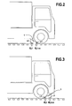
- the Figures 2 and 3 illustrate more precisely the realization of this comparison, the figure 2 representing a case in which the shim 1 was not placed correctly against a wheel of the vehicle V and the figure 3 representing a case in which the shim 1 has been correctly positioned against this wheel.
- the labels E are numbered from 1 to N from the Q platform, and the analysis system holds, for each of the readers L1 and L2, the information of the form Ej, i representative of the label E both closest to this reader and closest to the quay Q, that is to say, in other words, the information of the form Ej, i coming from the set of labels placed in the vicinity of each of the readers for which the index i is the lowest.
- the analysis system can thus deduce information of the form Ej, i and Ej, i + has retained for each of between them information representative of the direction of placement of the hold 1 relative to the succession of labels E along the path to the wharf Q.
- the analysis system also collects from the proximity detector information representative of the proximity of the shim 1 with the wheel of the vehicle V against which it must be placed.
- the invention provides that the analysis system controls the display and signaling means 3 advantageously preferably arranged at the level of the platform Q to indicate to the personnel of this platform whether the loading operations and / or unloading vehicle V may or may not be undertaken.
- the invention provides that, in the case where the result of the comparison of the information received from the radio-identification tags and selected for each of the readers indicates that the wedge 1 is not placed correctly with regard to the meaning of succession labels E along the access path to platform Q, or in the case where the information collected from the proximity detector indicates that the hold is not placed sufficiently close to the vehicle wheel V, the analysis system controls the display and signaling means 3 to indicate to the dock staff that the loading and / or unloading operations of the vehicle V can not be undertaken.
- a display may, for example, take the form of the lighting of a red light at the level of the platform, possibly in combination with the start of a warning sound signal.
- the invention provides that the analysis system controls the means of display and signaling to indicate to the dock staff that the loading and / or unloading operations of the vehicle may be undertaken.
- a display can take the form of lighting a green light at the dock level.
- the shim 1 is removed from the wheel against which it was placed.
- the motion detector that it comprises then transmits motion information to the analysis system.
- the presence detector of the shim in turn transmits to the analysis system a return information of the shim on its support.
- the invention thus proposes simple means and equipment for handling operations (loading and unloading of goods) on a vehicle parked in relation to a wharf of a logistics unit can be undertaken under satisfactory conditions with regard to the immobilisation of this vehicle with regard to this wharf.
- the invention has a set of additional characteristics of the characteristics that have just been mentioned.
- the invention provides that the analysis system controls the display means 3 to indicate that the operation of loading and / or unloading can not be undertaken if the information from the detector proximity and from the L1 and L2 readers have not been received by the analysis system in a period of time previously fixed from the moment at which the detectors movement and presence of the hold on its support Wedge 2 transmitted to him the aforementioned information of movement of the hold 1 and removal of it from its support.
- the previously fixed period of time mentioned above analogous to a delay of the analysis system means, can be set on the basis of an average time required for the installation of the hold. against a wheel of a vehicle at the dock.
- the wedge stops transmitting its placement information once its position has been validated or conversely, it continues to transmit, to regular intervals (by way of non-limiting example at intervals of a few seconds, typically from 3 to 20), its position information to the analysis system, the invention provides automatic warning means of the operators of the state of immobilisation of the vehicle throughout the loading and / or unloading of the goods.
- the invention provides, since a signal is transmitted to the analysis system by the motion detector, signal representative of a significant displacement (that is to say representative of a displacement of which amplitude is greater than a previously defined threshold), a new validation of the presence of a tire in the immediate vicinity of the shim 1 is performed.
- this same analysis system If, in a period of time previously defined from the moment at which the analysis system has received significant movement information from the motion detector, this same analysis system has not received, from the detector proximity, an immediate vicinity information of a tire of the vehicle, it then controls a validation of the return of the shim 1 on the support with which it has been matched, and controls the display means 3 to signal an error (for example by lighting an orange or red indicator light) in the absence of reception, within a given period of time, from the presence detector, of a signal representative of the return of the shim on the support 2 with which she was matched.
- an error for example by lighting an orange or red indicator light
- a delay is triggered at the level of the analysis system, after which, if no immediate proximity information of a tire (representative of the immediate vicinity of the vehicle) has been received, a new timer is triggered at the level of the analysis system. If, after this second delay, no presence signal of the hold on the The medium with which it has been paired has not been received by the analysis system, which then controls the display means 3 to signal an error.
- the sensitivity of said proximity sensor can also be adjusted so that it is transmitted by it that the information relating to a distance from the shim relative to the tire greater than a previously defined threshold distance. It also follows that this ensures the immobilization of the vehicle in satisfactory conditions for the safety of operators and goods over the entire duration of the handling operations.
- the invention provides that the pairing of a shim with a shim support can be achieved only if no wedge previously paired with the support is in use. This makes it possible to avoid, in particular, any error that may result from the inadvertent replacement of a shim on a support other than that with which it was matched while the shim corresponding to this support is in use.
- the analysis system controls the display means 3 to indicate an error in the event of an attempt to replace a shim on a shim support 2 different from the one with which it was fitted. matched as long as the wedge previously paired with this hold bracket is in use.
- the wedge transmits, at regular intervals, to the analysis system, all or part of its placement information (information received from the radio-identification tags arranged along the path of access to the dock and / or proximity information of a tire of a vehicle).
- the invention can equally provide that each platform is equipped with an analysis system, or that a central analysis and supervision system manages all the platforms.
- the invention can equally provide that display means 3 are arranged on each of the platforms, or that the display is centralized for all the platforms, with a device for identifying each platform, or that both display systems are used concomitantly (display at each platform and centralized display).
- the detectors and readers placed on any shim removed from its support to be disposed against a wheel d a vehicle parked in front of any of the platforms will transmit the information they receive to all the analysis systems of all the platforms.
- the invention provides that only the analysis system corresponding to the platform equipped with the support with which the shim in question has previously been paired will control the processing means that it comprises for analyzing this information. It follows that only the display means 3 governed by this analysis system will be controlled by it.
- This particular point has a double advantage.
- it ensures the modularity of the installation according to the invention, and thus its potential application for low costs to logistics units whose capacity in terms of platforms may be called to vary.
- the mobile tracking device 1 here a shim intended to be placed against a wheel of a vehicle parked in front of a dock, may be of any type other than such to the extent that it is representative, by its position and its direction of placement with regard to the succession of radio-identification tags along the access road to the wharf, the immobilisation conditions of the vehicle in question.
- the number of radio-identification tag readers that includes such a mobile tracking device is not limited to two, this being the minimum number necessary for the operation of the equipment according to the invention as described above.
Landscapes
- Engineering & Computer Science (AREA)
- Mechanical Engineering (AREA)
- Traffic Control Systems (AREA)
- Radar Systems Or Details Thereof (AREA)
- Load-Engaging Elements For Cranes (AREA)
- Mobile Radio Communication Systems (AREA)
- Control And Safety Of Cranes (AREA)
- Jib Cranes (AREA)
- Ship Loading And Unloading (AREA)
- Preliminary Treatment Of Fibers (AREA)
Claims (9)
- Sicherheitseinrichtung für Rampen zur Be- und Entladung von Waren in und aus an die Rampe herangeführten Fahrzeugen, bei der jeder Rampe zugeordnet ist:- eine mobile Kennzeichnungsvorrichtung (1), die in eine bestimmte Position in Bezug auf ein an die Rampe gebrachtes Fahrzeug anzuordnen ist,- dadurch gekennzeichnet, dass sie umfasst:- RFID-Transponder (E), die in Reihe entlang einem Zugangsweg zu der Rampe für die Transportfahrzeuge mit zu ladenden oder entladenden Waren angeordnet sind, wobei die Transponder Sender von Signalen sind, die eine kennzeichnende Transponder-Information über die Reihenfolge jedes Transponders in der Reihe tragen,- wobei die mobile Kennzeichnungsvorrichtung mindestens zwei Lesevorrichtungen (L1, L2) zum Senden von Funkwellen trägt, die geeignet sind, die von zwei unterschiedlichen Transpondern der Reihe emittierten Signale zu erfassen, um an ein Analysesystem Signale zu schicken, die die kennzeichnenden Transponder-Informationen, die jedem Transponder zugehörig sind, und Informationen der Lesegeräteigenschaft, die die zwei Lesegeräte voneinander unterscheiden, überbringen,- sowie Verarbeitungsmittel an dem Analysesystem, um aus der Gesamtheit der Transponder-Informationen und der Lesegeräteigenschaft-Informationen eine Bestätigung der Platzierung der Kennzeichnungsvorrichtung an der bestimmten Position herzuleiten, wobei eine vorgegebene Richtung zwischen den zwei Lesegeräten relativ zur Reihenfolge der Transponder in der Reihe berücksichtigt wird.
- Einrichtung nach Anspruch 1, dadurch gekennzeichnet, dass die mobile Kennzeichnungsvorrichtung (1) einen Näherungsdetektor umfasst, der geeignet ist, dem Analysesystem eine Information zu senden, die repräsentativ für die Nähe der Kennzeichnungsvorrichtung und des Fahrzeugs ist, in Bezug auf welche Letzteres angeordnet werden muss.
- Einrichtung nach einem oder dem anderen der Ansprüche 1 oder 2, dadurch gekennzeichnet, dass die mobile Kennzeichnungsvorrichtung (1) einen Bewegungsdetektor umfasst, der geeignet ist, dem Analysesystem eine Information zu senden, die repräsentativ für die Bewegung der Kennzeichnungsvorrichtung ist.
- Einrichtung nach einem beliebigen der Ansprüche 1 bis 3, dadurch gekennzeichnet, dass jeder Rampe gleichfalls ein Träger (2) für die Kennzeichnungsvorrichtung zugeordnet ist, der an eine elektrische Versorgungs- und Aufladevorrichtung der Kennzeichnungsvorrichtung angeschlossen ist.
- Einrichtung nach Anspruch 4, dadurch gekennzeichnet, dass die Trägervorrichtung (2) einen Anwesenheitsdetektor aufweist, der geeignet ist, dem Analysesystem eine Information zu senden, die repräsentativ für die Anwesenheit oder Abwesenheit der mobilen Kennzeichnungsvorrichtung an dem Träger ist.
- Einrichtung nach einem beliebigen der Ansprüche 1 bis 5, dadurch gekennzeichnet, dass die Trägervorrichtung (2) mit Mitteln zum Lesen einer von der mobilen Vorrichtung (1) getragenen Identifikationsinformation sowie mit Mitteln zur Übertragung dieser Information an das Analysesystem ausgerüstet ist, damit dieses das paarweise Zusammenlegen der mobilen Vorrichtung und der Trägervorrichtung realisiert.
- Einrichtung nach einem beliebigen der Ansprüche 1 bis 6, dadurch gekennzeichnet, dass die mobile Kennzeichnungsvorrichtung (1) ein Bremsklotz ist, der vorgesehen ist, gegen das Rad eines an der Rampe stehenden Fahrzeugs angelegt zu werden, um seine Blockierung zu vervollständigen.
- Verwendung einer Einrichtung nach dem einen oder dem anderen der Ansprüche 6 oder 7, um die Realisierung von Förderoperationen der Waren zu oder aus dem vor der Rampe stehenden Fahrzeug zu bestätigen, dadurch gekennzeichnet, dass, sobald der Anwesenheitsdetektor dem Analysesystem eine Information des Nichtvorhandenseins der Kennzeichnungsvorrichtung (1) sendet, das Analysesystem Anzeigemittel (3) steuert, um anzuzeigen, dass die Förderoperationen vorgenommen werden können, wenn die folgenden Bedingungen kumulativ erfüllt sind:- Empfang durch das Analysesystem innerhalb einer vorher bestimmten Zeitspanne einer von dem Näherungsdetektor gesendeten Information, die für die Nähe der Kennzeichnungsvorrichtung und des Fahrzeugs repräsentativ ist,- Bestätigung der Anordnung der Kennzeichnungsvorrichtung in der vorbestimmten Position durch die Verarbeitungsmittel, indem eine vorbestimmte Richtung zwischen den Lesegeräten relativ zu der Reihenfolge der Transponder in der Reihe berücksichtigt wird.
- Verwendung einer Einrichtung nach dem einen oder dem anderen der Ansprüche 6 oder 7, um die Realisierung von Förderoperationen der Waren zu oder aus dem vor der Rampe stehenden Fahrzeug zu bestätigen, dadurch gekennzeichnet, dass, sobald die Anzeigemittel (3) von dem Analysesystem gemäß dem Anspruch 8 gesteuert wurden und die Förderoperationen durchgeführt wurden, das Analysesystem die Anzeigemittel (3) steuert, um anzuzeigen, dass die mobile Kennzeichnungsvorrichtung erneut für ein anderes Fahrzeug verwendet werden kann, wenn die folgenden Bedingungen kumulativ erfüllt sind:- Empfang einer Information der Bewegung der mobilen Kennzeichnungsvorrichtung, die von dem Bewegungsdetektor gesendet wird, durch Analysesystem,- Nichtvorhandensein einer Näherungsinformation der mobilen Kennzeichnungsvorrichtung (1) und des Fahrzeugs,- Empfang durch das Analysesystem einer Information des Vorhandenseins der mobilen Kennzeichnungsvorrichtung auf ihrem Träger (2) in einer vorher bestimmten Zeitspanne, gerechnet von dem Moment des Empfangs des Bewegungssignals.
Priority Applications (1)
| Application Number | Priority Date | Filing Date | Title |
|---|---|---|---|
| PL09005609T PL2113476T3 (pl) | 2008-04-28 | 2009-04-22 | Wyposażenie zabezpieczające dla ramp ładowania i wyładowania towarów |
Applications Claiming Priority (1)
| Application Number | Priority Date | Filing Date | Title |
|---|---|---|---|
| FR0802414A FR2930533B1 (fr) | 2008-04-28 | 2008-04-28 | Equipement de securite pour quais de chargement ou dechargement de marchandises |
Publications (2)
| Publication Number | Publication Date |
|---|---|
| EP2113476A1 EP2113476A1 (de) | 2009-11-04 |
| EP2113476B1 true EP2113476B1 (de) | 2011-10-26 |
Family
ID=39967621
Family Applications (1)
| Application Number | Title | Priority Date | Filing Date |
|---|---|---|---|
| EP09005609A Not-in-force EP2113476B1 (de) | 2008-04-28 | 2009-04-22 | Sicherheitsvorrichtung für Verladerampen oder Entladerampen |
Country Status (8)
| Country | Link |
|---|---|
| US (1) | US7999680B2 (de) |
| EP (1) | EP2113476B1 (de) |
| AT (1) | ATE530480T1 (de) |
| DK (1) | DK2113476T3 (de) |
| ES (1) | ES2373883T3 (de) |
| FR (1) | FR2930533B1 (de) |
| PL (1) | PL2113476T3 (de) |
| PT (1) | PT2113476E (de) |
Families Citing this family (16)
| Publication number | Priority date | Publication date | Assignee | Title |
|---|---|---|---|---|
| US20080157947A1 (en) * | 2006-12-28 | 2008-07-03 | Neil Hutton | System and method for guiding an aircraft to a stopping position |
| WO2014074955A1 (en) | 2012-11-08 | 2014-05-15 | Distal Access, Llc | Apparatus for rotating medical devices, systems including the apparatus, and associated methods |
| ES2642835T3 (es) | 2013-11-29 | 2017-11-20 | 9172-9863 Québec Inc. | Calzo de rueda |
| WO2016191882A1 (en) | 2015-06-03 | 2016-12-08 | 9172-9863 Québec Inc. | Bidirectional wheel chock restraint system |
| US11305953B2 (en) | 2016-05-03 | 2022-04-19 | Assa Abloy Entrance Systems Ab | Control systems for operation of loading dock equipment, and associated methods of manufacture and use |
| US11285932B2 (en) * | 2017-06-05 | 2022-03-29 | Rite-Hite Holding Corporation | Wheel chock alarm systems and related methods |
| EP3681771B1 (de) | 2017-09-14 | 2023-06-07 | 9172-9863 Québec Inc. | Radbremsblock mit verriegelungsmechanismus |
| CA3119201A1 (en) | 2018-11-09 | 2020-05-14 | 9172-9863 Quebec Inc. | Wheel chock handling unit and method |
| US10494205B1 (en) * | 2018-12-06 | 2019-12-03 | Assa Abloy Entrance Systems Ab | Remote loading dock authorization systems and methods |
| US10676295B1 (en) * | 2019-02-15 | 2020-06-09 | Rite-Hite Holding Corporation | Monitoring and alerting systems for detecting hazardous conditions at loading docks |
| CN110728407A (zh) * | 2019-10-15 | 2020-01-24 | 秒针信息技术有限公司 | 货物的装配方法及装置 |
| US11702304B2 (en) | 2020-05-14 | 2023-07-18 | Blue Giant Equipment Corporation | Loading-dock signaling system incorporating a wheel chock having an illuminated signal |
| US12297062B1 (en) | 2020-09-21 | 2025-05-13 | The Chamberlain Group Llc. | System and method for restraining a vehicle proximate a loading dock |
| USD987542S1 (en) | 2021-03-22 | 2023-05-30 | 9172-9863 Québec Inc. | Wheel chock |
| USD995394S1 (en) | 2021-03-22 | 2023-08-15 | 9172-9863 Québec Inc. | Wheel chock |
| US12400175B2 (en) | 2021-11-30 | 2025-08-26 | Assa Abloy Entrance Systems Ab | Trailer validation systems |
Family Cites Families (4)
| Publication number | Priority date | Publication date | Assignee | Title |
|---|---|---|---|---|
| US5260694A (en) * | 1992-01-10 | 1993-11-09 | Ndc Automation, Inc. | Automatic article tracking system for manually operated delivery system |
| US8497761B2 (en) * | 2005-01-13 | 2013-07-30 | Rite-Hite Holding Corporation | System and method for remotely controlling docking station components |
| WO2007097767A2 (en) * | 2006-02-21 | 2007-08-30 | United States Postal Service | Systems and methods for creating on-demand routes for powered industrial vehicles |
| US7907052B2 (en) * | 2007-09-17 | 2011-03-15 | Delaney Jr John B | Enhanced firefighter door chock |
-
2008
- 2008-04-28 FR FR0802414A patent/FR2930533B1/fr not_active Expired - Fee Related
-
2009
- 2009-04-22 PT PT09005609T patent/PT2113476E/pt unknown
- 2009-04-22 ES ES09005609T patent/ES2373883T3/es active Active
- 2009-04-22 DK DK09005609.4T patent/DK2113476T3/da active
- 2009-04-22 AT AT09005609T patent/ATE530480T1/de active
- 2009-04-22 PL PL09005609T patent/PL2113476T3/pl unknown
- 2009-04-22 EP EP09005609A patent/EP2113476B1/de not_active Not-in-force
- 2009-04-28 US US12/453,055 patent/US7999680B2/en not_active Expired - Fee Related
Also Published As
| Publication number | Publication date |
|---|---|
| PT2113476E (pt) | 2012-01-17 |
| US7999680B2 (en) | 2011-08-16 |
| ATE530480T1 (de) | 2011-11-15 |
| EP2113476A1 (de) | 2009-11-04 |
| PL2113476T3 (pl) | 2012-02-29 |
| FR2930533A1 (fr) | 2009-10-30 |
| ES2373883T3 (es) | 2012-02-09 |
| DK2113476T3 (da) | 2012-01-02 |
| US20090267744A1 (en) | 2009-10-29 |
| FR2930533B1 (fr) | 2010-04-23 |
Similar Documents
| Publication | Publication Date | Title |
|---|---|---|
| EP2113476B1 (de) | Sicherheitsvorrichtung für Verladerampen oder Entladerampen | |
| EP3152097B1 (de) | Parkhilfesystem vorrichtung und fahrzeug mit einer derartigen vorrichtung | |
| EP1950694B1 (de) | Gesichertes Warenüberwachungssystem | |
| EP0476026B1 (de) | Verfahren und vorrichtung zur abrechnung und nachprüfung von gegenständen | |
| EP1429277B1 (de) | Identifizierungsverkleidung für zu sortierende Gegenstände | |
| CA3010672C (fr) | Systeme de convoyage de supports pour recipients d'echantillons de liquide biologique, et systeme d'analyse automatique comprenant un tel systeme de convoyage | |
| CA2367310C (fr) | Dispositif et procede pour la localisation ponctuelle d'un vehicule ferroviaire le long d'une voie ferree equipee de balises et antenne destinee a equiper un tel dispositif | |
| EP0185579B1 (de) | Verfahren zur Verschiebung eines beweglichen Systems, das durch einen elektrischen Motor in einer gegebenen Bahn angetrieben wird | |
| EP1429272B1 (de) | System zum Ansammeln und zur automatischen Prüfung von Bestellungen von Waren | |
| EP2096611A1 (de) | Verfahren und Vorrichtung zur Multitechnologie-Erkennung in einem Fahrzeug | |
| CA3009899A1 (fr) | Systeme de securisation pour un ensemble de couplage electromecanique, station de recharge d'un vehicule electrique munie d'un tel systeme et procede de couplage associe | |
| EP1399878A1 (de) | System und verfahren zur erkennung von personen oder objekten in definitiven bereichen, die jeweils mit mindestens einem eingang versehen sind | |
| FR3030759A1 (fr) | Systeme d'evaluation de la vitesse d'un pneumatique | |
| EP2423708B1 (de) | System und Verfahren zur Erfassung eines Zielobjekts | |
| CA2884759A1 (en) | Automatic bag drop method and system | |
| WO2008116976A1 (fr) | Dispositif de détection du passage d'objets portant une étiquette rfid, procédé et système utilisant un tel dispositif | |
| EP3433579B1 (de) | Verfahren und system zum auffinden von transportwagen | |
| EP1071496B2 (de) | Verfahren zum identifizierung eines sportgeräts, insbesondere snowboard oder surfboard oder wassersportfahrzeug | |
| FR2982688A1 (fr) | Procede et systeme de detection securisee d'une etiquette electronique rfid | |
| EP1258829A1 (de) | Vorrichtung zur Detektion von Personen oder Objekten in abgegrenzten Räumen mit einem Eingang | |
| EP4214655B1 (de) | Drive-thru-system zur lieferung einer bestellung | |
| FR2915599A1 (fr) | Systeme de localisation d'un conteneur dans une zone de stockage et procede de localisation associe | |
| FR3094116A1 (fr) | Procede suivi bagage | |
| FR3082830A1 (fr) | Systeme aeroportuaire anticollision | |
| FR3146304A1 (fr) | Bateau de transport de marchandises comportant un bras manipulateur pour le transbordement de marchandises |
Legal Events
| Date | Code | Title | Description |
|---|---|---|---|
| PUAI | Public reference made under article 153(3) epc to a published international application that has entered the european phase |
Free format text: ORIGINAL CODE: 0009012 |
|
| AK | Designated contracting states |
Kind code of ref document: A1 Designated state(s): AT BE BG CH CY CZ DE DK EE ES FI FR GB GR HR HU IE IS IT LI LT LU LV MC MK MT NL NO PL PT RO SE SI SK TR |
|
| 17P | Request for examination filed |
Effective date: 20100409 |
|
| GRAP | Despatch of communication of intention to grant a patent |
Free format text: ORIGINAL CODE: EPIDOSNIGR1 |
|
| GRAS | Grant fee paid |
Free format text: ORIGINAL CODE: EPIDOSNIGR3 |
|
| GRAA | (expected) grant |
Free format text: ORIGINAL CODE: 0009210 |
|
| AK | Designated contracting states |
Kind code of ref document: B1 Designated state(s): AT BE BG CH CY CZ DE DK EE ES FI FR GB GR HR HU IE IS IT LI LT LU LV MC MK MT NL NO PL PT RO SE SI SK TR |
|
| REG | Reference to a national code |
Ref country code: GB Ref legal event code: FG4D Free format text: NOT ENGLISH |
|
| REG | Reference to a national code |
Ref country code: CH Ref legal event code: EP |
|
| REG | Reference to a national code |
Ref country code: IE Ref legal event code: FG4D |
|
| REG | Reference to a national code |
Ref country code: SE Ref legal event code: TRGR |
|
| REG | Reference to a national code |
Ref country code: NL Ref legal event code: T3 |
|
| REG | Reference to a national code |
Ref country code: DE Ref legal event code: R096 Ref document number: 602009003214 Country of ref document: DE Effective date: 20111229 |
|
| REG | Reference to a national code |
Ref country code: DK Ref legal event code: T3 |
|
| REG | Reference to a national code |
Ref country code: PT Ref legal event code: SC4A Free format text: AVAILABILITY OF NATIONAL TRANSLATION Effective date: 20120109 |
|
| REG | Reference to a national code |
Ref country code: ES Ref legal event code: FG2A Ref document number: 2373883 Country of ref document: ES Kind code of ref document: T3 Effective date: 20120209 |
|
| REG | Reference to a national code |
Ref country code: PL Ref legal event code: T3 |
|
| LTIE | Lt: invalidation of european patent or patent extension |
Effective date: 20111026 |
|
| PG25 | Lapsed in a contracting state [announced via postgrant information from national office to epo] |
Ref country code: LT Free format text: LAPSE BECAUSE OF FAILURE TO SUBMIT A TRANSLATION OF THE DESCRIPTION OR TO PAY THE FEE WITHIN THE PRESCRIBED TIME-LIMIT Effective date: 20111026 Ref country code: NO Free format text: LAPSE BECAUSE OF FAILURE TO SUBMIT A TRANSLATION OF THE DESCRIPTION OR TO PAY THE FEE WITHIN THE PRESCRIBED TIME-LIMIT Effective date: 20120126 Ref country code: IS Free format text: LAPSE BECAUSE OF FAILURE TO SUBMIT A TRANSLATION OF THE DESCRIPTION OR TO PAY THE FEE WITHIN THE PRESCRIBED TIME-LIMIT Effective date: 20120226 |
|
| PG25 | Lapsed in a contracting state [announced via postgrant information from national office to epo] |
Ref country code: HR Free format text: LAPSE BECAUSE OF FAILURE TO SUBMIT A TRANSLATION OF THE DESCRIPTION OR TO PAY THE FEE WITHIN THE PRESCRIBED TIME-LIMIT Effective date: 20111026 Ref country code: GR Free format text: LAPSE BECAUSE OF FAILURE TO SUBMIT A TRANSLATION OF THE DESCRIPTION OR TO PAY THE FEE WITHIN THE PRESCRIBED TIME-LIMIT Effective date: 20120127 Ref country code: LV Free format text: LAPSE BECAUSE OF FAILURE TO SUBMIT A TRANSLATION OF THE DESCRIPTION OR TO PAY THE FEE WITHIN THE PRESCRIBED TIME-LIMIT Effective date: 20111026 Ref country code: SI Free format text: LAPSE BECAUSE OF FAILURE TO SUBMIT A TRANSLATION OF THE DESCRIPTION OR TO PAY THE FEE WITHIN THE PRESCRIBED TIME-LIMIT Effective date: 20111026 |
|
| PG25 | Lapsed in a contracting state [announced via postgrant information from national office to epo] |
Ref country code: CY Free format text: LAPSE BECAUSE OF FAILURE TO SUBMIT A TRANSLATION OF THE DESCRIPTION OR TO PAY THE FEE WITHIN THE PRESCRIBED TIME-LIMIT Effective date: 20111026 |
|
| PG25 | Lapsed in a contracting state [announced via postgrant information from national office to epo] |
Ref country code: SK Free format text: LAPSE BECAUSE OF FAILURE TO SUBMIT A TRANSLATION OF THE DESCRIPTION OR TO PAY THE FEE WITHIN THE PRESCRIBED TIME-LIMIT Effective date: 20111026 Ref country code: EE Free format text: LAPSE BECAUSE OF FAILURE TO SUBMIT A TRANSLATION OF THE DESCRIPTION OR TO PAY THE FEE WITHIN THE PRESCRIBED TIME-LIMIT Effective date: 20111026 Ref country code: BG Free format text: LAPSE BECAUSE OF FAILURE TO SUBMIT A TRANSLATION OF THE DESCRIPTION OR TO PAY THE FEE WITHIN THE PRESCRIBED TIME-LIMIT Effective date: 20120126 Ref country code: CZ Free format text: LAPSE BECAUSE OF FAILURE TO SUBMIT A TRANSLATION OF THE DESCRIPTION OR TO PAY THE FEE WITHIN THE PRESCRIBED TIME-LIMIT Effective date: 20111026 |
|
| PG25 | Lapsed in a contracting state [announced via postgrant information from national office to epo] |
Ref country code: RO Free format text: LAPSE BECAUSE OF FAILURE TO SUBMIT A TRANSLATION OF THE DESCRIPTION OR TO PAY THE FEE WITHIN THE PRESCRIBED TIME-LIMIT Effective date: 20111026 |
|
| PLBE | No opposition filed within time limit |
Free format text: ORIGINAL CODE: 0009261 |
|
| STAA | Information on the status of an ep patent application or granted ep patent |
Free format text: STATUS: NO OPPOSITION FILED WITHIN TIME LIMIT |
|
| 26N | No opposition filed |
Effective date: 20120727 |
|
| REG | Reference to a national code |
Ref country code: DE Ref legal event code: R097 Ref document number: 602009003214 Country of ref document: DE Effective date: 20120727 |
|
| PG25 | Lapsed in a contracting state [announced via postgrant information from national office to epo] |
Ref country code: MC Free format text: LAPSE BECAUSE OF NON-PAYMENT OF DUE FEES Effective date: 20120430 |
|
| PG25 | Lapsed in a contracting state [announced via postgrant information from national office to epo] |
Ref country code: MK Free format text: LAPSE BECAUSE OF FAILURE TO SUBMIT A TRANSLATION OF THE DESCRIPTION OR TO PAY THE FEE WITHIN THE PRESCRIBED TIME-LIMIT Effective date: 20111026 |
|
| PG25 | Lapsed in a contracting state [announced via postgrant information from national office to epo] |
Ref country code: FI Free format text: LAPSE BECAUSE OF FAILURE TO SUBMIT A TRANSLATION OF THE DESCRIPTION OR TO PAY THE FEE WITHIN THE PRESCRIBED TIME-LIMIT Effective date: 20111026 |
|
| PG25 | Lapsed in a contracting state [announced via postgrant information from national office to epo] |
Ref country code: MT Free format text: LAPSE BECAUSE OF FAILURE TO SUBMIT A TRANSLATION OF THE DESCRIPTION OR TO PAY THE FEE WITHIN THE PRESCRIBED TIME-LIMIT Effective date: 20111026 |
|
| PG25 | Lapsed in a contracting state [announced via postgrant information from national office to epo] |
Ref country code: TR Free format text: LAPSE BECAUSE OF FAILURE TO SUBMIT A TRANSLATION OF THE DESCRIPTION OR TO PAY THE FEE WITHIN THE PRESCRIBED TIME-LIMIT Effective date: 20111026 |
|
| PG25 | Lapsed in a contracting state [announced via postgrant information from national office to epo] |
Ref country code: LU Free format text: LAPSE BECAUSE OF NON-PAYMENT OF DUE FEES Effective date: 20120422 |
|
| PG25 | Lapsed in a contracting state [announced via postgrant information from national office to epo] |
Ref country code: HU Free format text: LAPSE BECAUSE OF FAILURE TO SUBMIT A TRANSLATION OF THE DESCRIPTION OR TO PAY THE FEE WITHIN THE PRESCRIBED TIME-LIMIT Effective date: 20090422 |
|
| REG | Reference to a national code |
Ref country code: FR Ref legal event code: PLFP Year of fee payment: 8 |
|
| REG | Reference to a national code |
Ref country code: FR Ref legal event code: PLFP Year of fee payment: 9 |
|
| REG | Reference to a national code |
Ref country code: FR Ref legal event code: CD Owner name: GPSYSTEMS, FR Effective date: 20170419 Ref country code: FR Ref legal event code: CJ Effective date: 20170419 |
|
| REG | Reference to a national code |
Ref country code: FR Ref legal event code: PLFP Year of fee payment: 10 |
|
| PGFP | Annual fee paid to national office [announced via postgrant information from national office to epo] |
Ref country code: IE Payment date: 20180424 Year of fee payment: 10 Ref country code: DE Payment date: 20180430 Year of fee payment: 10 Ref country code: CH Payment date: 20180425 Year of fee payment: 10 Ref country code: DK Payment date: 20180424 Year of fee payment: 10 Ref country code: PT Payment date: 20180418 Year of fee payment: 10 Ref country code: ES Payment date: 20180514 Year of fee payment: 10 |
|
| PGFP | Annual fee paid to national office [announced via postgrant information from national office to epo] |
Ref country code: FR Payment date: 20180427 Year of fee payment: 10 Ref country code: IT Payment date: 20180419 Year of fee payment: 10 Ref country code: PL Payment date: 20180409 Year of fee payment: 10 Ref country code: NL Payment date: 20180427 Year of fee payment: 10 Ref country code: AT Payment date: 20180426 Year of fee payment: 10 Ref country code: BE Payment date: 20180419 Year of fee payment: 10 |
|
| PGFP | Annual fee paid to national office [announced via postgrant information from national office to epo] |
Ref country code: SE Payment date: 20180419 Year of fee payment: 10 |
|
| PGFP | Annual fee paid to national office [announced via postgrant information from national office to epo] |
Ref country code: GB Payment date: 20180427 Year of fee payment: 10 |
|
| REG | Reference to a national code |
Ref country code: DE Ref legal event code: R119 Ref document number: 602009003214 Country of ref document: DE |
|
| REG | Reference to a national code |
Ref country code: CH Ref legal event code: PL |
|
| REG | Reference to a national code |
Ref country code: DK Ref legal event code: EBP Effective date: 20190430 |
|
| REG | Reference to a national code |
Ref country code: SE Ref legal event code: EUG |
|
| REG | Reference to a national code |
Ref country code: NL Ref legal event code: MM Effective date: 20190501 |
|
| REG | Reference to a national code |
Ref country code: AT Ref legal event code: MM01 Ref document number: 530480 Country of ref document: AT Kind code of ref document: T Effective date: 20190422 |
|
| REG | Reference to a national code |
Ref country code: BE Ref legal event code: MM Effective date: 20190430 |
|
| GBPC | Gb: european patent ceased through non-payment of renewal fee |
Effective date: 20190422 |
|
| PG25 | Lapsed in a contracting state [announced via postgrant information from national office to epo] |
Ref country code: PT Free format text: LAPSE BECAUSE OF NON-PAYMENT OF DUE FEES Effective date: 20191022 Ref country code: AT Free format text: LAPSE BECAUSE OF NON-PAYMENT OF DUE FEES Effective date: 20190422 Ref country code: SE Free format text: LAPSE BECAUSE OF NON-PAYMENT OF DUE FEES Effective date: 20190423 Ref country code: GB Free format text: LAPSE BECAUSE OF NON-PAYMENT OF DUE FEES Effective date: 20190422 Ref country code: NL Free format text: LAPSE BECAUSE OF NON-PAYMENT OF DUE FEES Effective date: 20190501 Ref country code: CH Free format text: LAPSE BECAUSE OF NON-PAYMENT OF DUE FEES Effective date: 20190430 Ref country code: LI Free format text: LAPSE BECAUSE OF NON-PAYMENT OF DUE FEES Effective date: 20190430 Ref country code: DE Free format text: LAPSE BECAUSE OF NON-PAYMENT OF DUE FEES Effective date: 20191101 |
|
| PG25 | Lapsed in a contracting state [announced via postgrant information from national office to epo] |
Ref country code: FR Free format text: LAPSE BECAUSE OF NON-PAYMENT OF DUE FEES Effective date: 20190430 Ref country code: BE Free format text: LAPSE BECAUSE OF NON-PAYMENT OF DUE FEES Effective date: 20190430 |
|
| PG25 | Lapsed in a contracting state [announced via postgrant information from national office to epo] |
Ref country code: IT Free format text: LAPSE BECAUSE OF NON-PAYMENT OF DUE FEES Effective date: 20190422 Ref country code: DK Free format text: LAPSE BECAUSE OF NON-PAYMENT OF DUE FEES Effective date: 20190430 Ref country code: IE Free format text: LAPSE BECAUSE OF NON-PAYMENT OF DUE FEES Effective date: 20190422 |
|
| REG | Reference to a national code |
Ref country code: ES Ref legal event code: FD2A Effective date: 20200831 |
|
| PG25 | Lapsed in a contracting state [announced via postgrant information from national office to epo] |
Ref country code: ES Free format text: LAPSE BECAUSE OF NON-PAYMENT OF DUE FEES Effective date: 20190423 |
|
| PG25 | Lapsed in a contracting state [announced via postgrant information from national office to epo] |
Ref country code: PL Free format text: LAPSE BECAUSE OF NON-PAYMENT OF DUE FEES Effective date: 20190422 |