EP2113419B2 - Covering device for the interior of a vehicle - Google Patents
Covering device for the interior of a vehicle Download PDFInfo
- Publication number
- EP2113419B2 EP2113419B2 EP09009536.5A EP09009536A EP2113419B2 EP 2113419 B2 EP2113419 B2 EP 2113419B2 EP 09009536 A EP09009536 A EP 09009536A EP 2113419 B2 EP2113419 B2 EP 2113419B2
- Authority
- EP
- European Patent Office
- Prior art keywords
- cable
- driver
- guide rail
- pull rod
- setting
- Prior art date
- Legal status (The legal status is an assumption and is not a legal conclusion. Google has not performed a legal analysis and makes no representation as to the accuracy of the status listed.)
- Active
Links
- 238000004804 winding Methods 0.000 claims abstract description 26
- 230000008878 coupling Effects 0.000 claims description 13
- 238000010168 coupling process Methods 0.000 claims description 13
- 238000005859 coupling reaction Methods 0.000 claims description 13
- 230000007246 mechanism Effects 0.000 claims description 6
- 238000012546 transfer Methods 0.000 claims description 5
- 238000005096 rolling process Methods 0.000 abstract description 2
- 230000001360 synchronised effect Effects 0.000 description 10
- 230000005540 biological transmission Effects 0.000 description 7
- 238000011161 development Methods 0.000 description 7
- 230000018109 developmental process Effects 0.000 description 7
- 230000006835 compression Effects 0.000 description 5
- 238000007906 compression Methods 0.000 description 5
- 230000000694 effects Effects 0.000 description 5
- 230000002457 bidirectional effect Effects 0.000 description 3
- 238000009434 installation Methods 0.000 description 3
- 238000004519 manufacturing process Methods 0.000 description 3
- 230000009471 action Effects 0.000 description 2
- 238000005452 bending Methods 0.000 description 2
- 230000010339 dilation Effects 0.000 description 2
- 230000005484 gravity Effects 0.000 description 2
- 230000000977 initiatory effect Effects 0.000 description 2
- 230000035882 stress Effects 0.000 description 2
- 230000002411 adverse Effects 0.000 description 1
- 230000032683 aging Effects 0.000 description 1
- 230000009286 beneficial effect Effects 0.000 description 1
- 230000008901 benefit Effects 0.000 description 1
- 230000015572 biosynthetic process Effects 0.000 description 1
- 239000000969 carrier Substances 0.000 description 1
- 238000010276 construction Methods 0.000 description 1
- 238000013461 design Methods 0.000 description 1
- 239000012530 fluid Substances 0.000 description 1
- 239000011521 glass Substances 0.000 description 1
- 238000012423 maintenance Methods 0.000 description 1
- 238000000034 method Methods 0.000 description 1
- 230000002093 peripheral effect Effects 0.000 description 1
- 239000013641 positive control Substances 0.000 description 1
- 230000008569 process Effects 0.000 description 1
- 230000002035 prolonged effect Effects 0.000 description 1
- 230000001681 protective effect Effects 0.000 description 1
- 238000004904 shortening Methods 0.000 description 1
- 230000037072 sun protection Effects 0.000 description 1
Images


Classifications
-
- B—PERFORMING OPERATIONS; TRANSPORTING
- B60—VEHICLES IN GENERAL
- B60R—VEHICLES, VEHICLE FITTINGS, OR VEHICLE PARTS, NOT OTHERWISE PROVIDED FOR
- B60R5/00—Compartments within vehicle body primarily intended or sufficiently spacious for trunks, suit-cases, or the like
- B60R5/04—Compartments within vehicle body primarily intended or sufficiently spacious for trunks, suit-cases, or the like arranged at rear of vehicle
- B60R5/044—Compartments within vehicle body primarily intended or sufficiently spacious for trunks, suit-cases, or the like arranged at rear of vehicle luggage covering means, e.g. parcel shelves
- B60R5/045—Compartments within vehicle body primarily intended or sufficiently spacious for trunks, suit-cases, or the like arranged at rear of vehicle luggage covering means, e.g. parcel shelves collapsible or transformable
- B60R5/047—Compartments within vehicle body primarily intended or sufficiently spacious for trunks, suit-cases, or the like arranged at rear of vehicle luggage covering means, e.g. parcel shelves collapsible or transformable collapsible by rolling-up
Definitions
- the invention relates to a loading space covering device according to the preamble of claim 1.
- Such protective devices for the interior of a motor vehicle are for example from the EP 0 941 176 B1 as well as from the EP 1 084 907 A2 well known. So is in the EP 1 084 907 A2 described a cargo space cover with a tarpaulin, which is held on a roller blind. At its front front end in the pull-out direction, the tarpaulin is provided with a pull-out rod which extends across its entire width and is horizontally displaceably mounted with guide ends at opposite front ends laterally beyond the tarpaulin.
- a driver slide serving as a coupling member is mounted such that it can move linearly.
- the two carrier slides of one of the guide profiles can be moved in synchronism with one another in the respective guide profile by means of a drive device.
- Bending-elastic, tension and compression-resistant racks serve as transmission means for the driving slides.
- Bowden cables, threaded shafts, rope or belt drives can also be provided.
- the carriage is synchronized by means of an electronic control via two separate electric drive motors for both sides of the load compartment cover.
- the separate arrangement of two electric drive motors also requires complex adjustment and calibration of the system. Furthermore, by using two separate electric drive motors appropriate space in the motor vehicle is required, which contributes to an increase in weight of the vehicle.
- the power transmission between the drive motor and drivers can be adapted to different installation dimensions of different motor vehicle types or models only to a limited extent by means of tension and pressure-resistant force transmission means, such as, for example, riser cables running within rigid guide tubes.
- tension and pressure-resistant force transmission means such as, for example, riser cables running within rigid guide tubes.
- rigid guide and power transmission means take up a large amount of space and are difficult to handle due to their bulky, inflexible structure during assembly.
- Such a bulky internal structure of a drive system is also noticeable when it is transported from an automotive supplier to the end customer, the automobile manufacturer. Because the bulky structure of such a drive system forces a very complex and thus costly transport between the manufacturing site of the drive module at the supplier and the final assembly of the motor vehicle at the automobile manufacturer.
- a cover roller blind for covering the loading space of passenger cars is also known, in which a positive guide device having two end positions for the pull rod is provided. This is designed in such a way that the roller blind can be automatically moved into an intermediate or comfort position, in which an enlarged access to the loading space located under the tarpaulin is created.
- a user covers the loading space opening by means of the cover blind before closing a vehicle tailgate. In this case, the drawbar is moved approximately manually into a closed position, with the drawbar being brought into a further state in which the Drawbar is held in the closed position depending on the position of the tailgate. When the tailgate is opened, the cover roller blind is immediately and automatically transferred to the half-open intermediate position.
- a positive guide device having two end positions for the pull rod is provided. This is designed in such a way that the roller blind can be automatically moved into an intermediate or comfort position, in which an enlarged access to the loading space located under the tarpaulin is created.
- Different versions are described in which a user covers the loading space
- the deflection devices each consist of a pair of rollers, which are rotatably mounted on a bearing block, which in turn is firmly connected to the front frame part of the frame arrangement via compression springs.
- the compression springs ensure that the combination of roller blind web and ropes is always under tension, so that the roller blind web is tensioned in every position, just like the ropes.
- a window roller blind for a vehicle window is known, with a roller blind which has a section fastened to a rotatably mounted winding shaft and a section which is remote from the winding shaft and is connected via a pull bow to sliding elements or slides which are longitudinally displaceable in lateral, parallel guide rails are led.
- the roller blind is pulled off the winding shaft via compression and / or bending resistant Actuating means, for example in the form of flexible push rods, pressure-resistant toothed belts or riser cables, which are actuated by a drive device.
- cover and blind devices are from the DE-C-19910830 , of the DE-A-10123420 , of the EP-A-1279537 , of the DE-C-19944948 , of the WO-A-98/24657 , of the DE-A-10224157 , of the EP-A-1334875 , of the DE-U-202006019796 , of the JP-A-11286243 , of the DE-A-10216186 , of the DE-A-10123420 , of the DE-B-10151068 , of the DE-U-202004007896 , of the DE-C-19836705 , of the DE-U-7819208 , of the DE-B-10356911 , of the DE-A-10 2005 049 999 , of the DE-A-1386784 , of the DE 198 25 353 C2 and the DE 10 2006 047 348 A1 known.
- the present invention is based on the object of providing a loading space covering device for the motor vehicle interior which enables a space-saving and flexible arrangement in the motor vehicle which is as space-saving as possible and which can be moved smoothly even after prolonged use.
- the invention relates to a loading space covering device for the motor vehicle interior with a covering or blind sheet that can be stretched flatly and rolled up on a rotatably mounted winding shaft, on which a pull rod is arranged, which is positively guided with its opposite end sections between two essentially parallel guide rails and that with an adjustment drive can be coupled.
- a pull rod is arranged, which is positively guided with its opposite end sections between two essentially parallel guide rails and that with an adjustment drive can be coupled.
- the second driver is provided on each guide rail for transferring the pull rod from an initial position to an end position. This driver can be used for unidirectional coupling between the drive and the pull rod, in particular to transfer the pull rod into an end position.
- the second driver can also be fixed or detachably coupled to the pull rod, so that a bidirectional movement of this driver can also be transmitted directly to the pull rod.
- this embodiment which has only one driver per guide rail, is already suitable for transferring the pull rod bidirectionally, ie both into its starting position and into its end position and back.
- the pull rod connected to the cover sheet is releasably arranged on the carrier, can be clipped on to the carrier, for example, or fixed to the carrier by means of a fluid connection means, for example with the aid of an undercut formed on the carrier.
- the tie rod and driver are fastened in such a way that the driver essentially exerts a pull-out movement on the tie rod, while a spring mechanism, for example a spring motor, arranged in the region of the winding shaft exerts an opposing restoring force on the tie rod.
- the driver of each guide rail is coupled to the adjustment drive by means of a flexible traction device in the form of a cable pull.
- the A traction device which provides a translatory coupling between the adjustment drive and the driver that can be moved along the rail, is assigned a length adjustment device. This is used to compensate for any elongations that occur during operation or for dilation of the traction device.
- the traction means is designed as a cable pull
- its inner cable which is designed as a rope strand
- constant stress which can be a few millimeters if not centimeters.
- Such elongation leads to a systemless or rope-less in the power transmission train, which can have an adverse effect on the entire adjustment mechanism. If the system or rope lots are not compensated, they are used up at the beginning of an adjustment movement that begins before an adjustment movement can be transmitted to the driver via the traction means.
- any system or rope loose that occurs can be compensated for by means of the length adjustment device, so that the cable pull is always under a required tension in every conceivable operating position, so that when a rotary movement initiated by the actuator is used, this can be transferred directly to a corresponding adjustment movement of the drivers.
- the length adjustment device effects a "virtual" extension of the hose enveloping the inner cable corresponding to the operational lengthening of the inner cable.
- a length adjustment device typically has two components which can be displaced relative to one another in the axial direction, ie in the direction of the cable extension, for example a sleeve and an extension guided in a sleeve, both components being connected to the sleeve or the hose of the actuating cable.
- the extension and the sleeve receiving the extension typically have mutually corresponding locking elements or are with separate locking elements coupled, which pull apart, that is, an axial lengthening of the length adjustment device, but prevent the opposite pushing together of the two components.
- the pulling apart of the length adjustment device or moving the extension in the axial direction out of a sleeve can take place under the action of a spring, so that when systemless occurs, for example as a result of an operation-related lengthening of the inner cable, the two components of the length adjustment device automatically by a predetermined amount Be moved apart.
- the system or rope-less can be compensated for by a corresponding elongation of the hose surrounding the inner cable, so that the entire operating cable is again under the required tension.
- the two drivers that can be moved on different guide rails are also directly coupled to one another via the traction means.
- the coupling of the two drivers via the traction means is such that when the adjustment drive is actuated, the traction means execute a synchronous movement which is aligned with one another.
- a flexible traction means can advantageously provide a universal adjustment device for a cover roller blind that can be adapted to a wide variety of installation dimensions and installation requirements, and which requires only a single adjustment drive.
- the second driver only exerts a unidirectional adjustment movement on the pull rod, namely in the direction of its end position.
- a spring motor is provided in the region of the winding shaft, within a winding cassette.
- the flexible traction means designed as a cable is articulated on an end section of the guide rails and guided on a section opposite the end section via a deflection.
- the core of the cable is guided from a hose socket provided at the end section of the guide rail to the deflection roller and from there back to a further hose socket provided at the end section of the guide rail.
- a driver is connected to each of the two cable pull strands of a guide rail and is provided at least for transferring the pull rod which is positively guided on the guide rail into its end position.
- the formation of a flexible cable as a movement or force transmission means from the adjustment drive to the drivers and thus to the pull rod is advantageous compared to compression-resistant tension-pressure media, such as threaded spindles, racks or riser cables, as a result of the deflection, a bidirectional movement of the drivers by initiation of a Pulling force can take place on one of the cable pull strands.
- the traction means is designed as a closed peripheral cable, to which the drivers of each guide rail that are operatively connected to the pull rod are coupled, with this cable pull, which preferably crosses the rails, coupling both drivers to the common one Actuator provides.
- two separate cable pulls can also be provided, which are articulated on the one hand on each driver and on the other hand on a common adjustment drive for both cable pulls.
- the coupling between the adjustment drive and the traction means by means of a cable drum is also advantageous.
- the cable drum which is typically in operative connection with a geared motor, has the effect that the core of the cable or actuating cable can be displaced in both directions with respect to the outer hose surrounding the core.
- each of these cable pulls is also advantageous to couple to the common drive by means of a single cable drum.
- This cable drum can be designed as a two-part cable drum with axially spaced and non-rotatably arranged cable drum sections, which are designed to receive a cable.
- the two cable drum sections can be arranged axially spaced from one another in relation to the axis of rotation of the cable drum or can be arranged to lie axially next to one another. In this way, a synchronous movement can be exercised on both cables when the adjustment drive is actuated.
- each of the two cables is assigned a separate length adjustment device.
- the length adjustment device can be arranged directly on the cable drum housing or to be integrated therein.
- the loading space covering device is provided for covering the loading space of a motor vehicle, in particular a passenger car.
- the loading space covering device has a cover sheet that can be rolled up and unrolled, such as a roller blind sheet, which can be rolled up onto a rotatably mounted winding shaft arranged within a winding cassette.
- a pull rod extending transversely or perpendicular to the rolling direction, which in turn is positively guided with its opposite end sections between the guide rails and can be coupled to an adjustment drive in the region of the guide rail.
- a locking member is provided, which can optionally be transferred to a locking position or release position.
- the locking member In its locking position, the locking member is designed to fix the pull rod which is positively guided on the guide rail in an end position.
- At least one first driver which can be moved along the guide rail can be provided, which is at least designed to transfer the locking member from its locking position into the release position in which the locking member releases the pull rod.
- the driver which can be moved along the guide rail thus not only serves, as is customary in the prior art, to couple between the adjusting drive and the pull rod, but it can also serve as an unlocking member for unlocking and releasing the pull rod within the scope of the invention.
- the at least first driver is in direct operative connection with the locking member during the unlocking process.
- the first driver is intended to cooperate with the locking member as a result of an adjustment movement running along the guide rail in such a way that the locking member is transferred from the locking position into the unlocking or release position.
- This release mechanism is therefore particularly low-maintenance and hardly susceptible to failure.
- the unlocking mechanism can be implemented in a particularly cost-effective manner, since for this purpose only a specially designed first driver has to be guided on an already existing guide rail.
- the winding shaft of the covering or roller blind web accommodated in a winding cassette is equipped with a spring mechanism, preferably with a spring motor, the covering web being unrolled or stretched against the spring force.
- the cover sheet can be rolled up automatically at least in some areas if the locking member releases the pull rod from the end position as a result of the movement of the first driver.
- the cover sheet or the cover roller blind can be transferred from the end position into a so-called comfort position in which the load space of a motor vehicle, for example, located under the cover sheet is released for loading or unloading at least in regions.
- the first driver is coupled to the adjustment drive.
- This has the advantage that no separate servomotor is required to unlock the pull rod from its end position, but that the adjustment drive which is present anyway for adjusting the cover sheet can also be used universally for initiating an unlocking. In this way, the entire loading space covering device can be realized with only a single adjustment drive.
- a second driver likewise movable along the guide rail, which is at least designed to move the pull rod along its To bring positive control into the end position.
- This second driver thus acts directly on the positively guided pull rod, while the first driver is intended to interact with the locking member.
- the second driver is positioned at least in this way on the guide rail opposite the pull rod and is also designed such that the pull rod can be moved along the guide rail by means of this second driver at least in one direction, namely along the extension direction.
- first and the second driver are directly coupled to the adjustment drive.
- the coupling of the first and the second driver to the guide rail is such that the two drivers carry out opposing adjustment movements along the guide rail during the operation of the adjustment drive.
- the two drivers provided along a common driver rail move towards and / or away from one another.
- the connection of the first and the second driver to the guide rail enables the drivers to be guided past one another.
- the drivers are slidably mounted on different sides of the guide rail or on the same side of the guide rail, but then at different heights.
- the arrangement of the two drivers on the same side of the guide rail, for example facing the cover sheet enables a space-saving construction of the entire cover device, in particular in the area of the guide rail which is preferably to be accommodated in a D-pillar of a motor vehicle.
- the locking member is designed as a pivotably mounted pawl with a run-on slope.
- This start-up slope acts when the Pull rod into the end position together with a pull rod section in such a way that the pawl is at least temporarily lifted out of its locking position, for example against gravity or against a spring force, in such a way that the pull rod can in turn be transferred to the intended end position in which the pawl again assumes its locking position and prevents the drawbar from automatically moving out of the end position.
- the pull rod In its end position, the pull rod then comes to rest, for example, on an undercut of the pawl, which preferably adjoins the run-on slope.
- the release of the pull rod and thus the cover sheet connected to the pull rod takes place via a pivoting movement of the locking member in its release position. This can either be done manually or initiated by the first driver.
- the first driver has an inclined surface which cooperates with a corresponding inclined surface of the locking member, so that the locking member is transferred from the locking position into the release position as a result of a corresponding adjustment movement along the guide rail.
- the inclined surface of the locking member interacting with the first driver, as well as its start-up bevel, which is in operative connection with the pull rod, can coincide.
- the inclined surface of the locking member which cooperates with a corresponding inclined surface of the first driver, and the starting bevel of the locking member are axially offset with respect to one another with respect to the pivot axis of the locking member. It is particularly advantageous here if the starting bevel and the inclined surface of the locking member have different angles, so that in particular when the locking member is initiated by the first driver in the Release position the locking member performs a greater pivoting movement than if it is transferred into the release position by moving the pull rod in its end position.
- the pull rod can be guided past the locking member without friction and contact when the locking member is in the released position.
- the inclined surface provided on the first driver is designed as a projection of the driver pointing away from the guide rail plane.
- This projection which extends essentially perpendicular to the rail plane, enables the first driver to move at least in sections into an area between the locking member and the guide rail when the locking member is transferred into its release position.
- the locking member has a convexly curved receptacle for the pull rod, in which the pull rod comes to rest in its end position, in particular when the locking member is in its locked position.
- the convexly curved receptacle of the locking member which is adapted to the cross-sectional profile of the drawbar, supports a secure and play-free fixation of the drawbar in its end position.
- the convexly curved receptacle of the locking member in this case in particular fixes the pull rod with respect to any movements perpendicular or transverse to the longitudinal extension of the guide rail.
- the second driver element has a projection designed as a driver stop, on which a receptacle is formed at least on the side surface facing the locking member.
- This, preferably convexly curved receptacle is designed to receive the tie rod profile.
- the driver-side receptacle therefore has a curvature corresponding to the cross-sectional profile of the pull rod.
- the second driver is not fixedly coupled to the pull rod, but is designed to move the pull rod only in one direction of movement along the guide rail.
- the second driver is accordingly arranged on the guide rail such that the pull rod is always between the second driver and the locking member. As soon as the pull rod is held in its end position by the locking member, the second driver can again be moved to a position on the guide rail, for example opposite the locking member.
- the receptacle for the pull rod on the second driver can be designed in such a way that it only partially encompasses the pull rod in the circumferential direction up to approximately 90 °, so that the pull rod, when it has been moved into its end position by means of the second driver, seamlessly from the receptacle of the locking member can be included.
- the second driver, or the projection formed on the second driver can be guided past the locking member, and that the second driver, or the projection formed thereon, can be moved in a plane parallel to the guide rail plane, which is outside the pivot plane of the locking member. This can in particular collisions between the locking member and the second driver are avoided and prevented.
- the first and the second driver are directly coupled to one another via a traction means, the traction means being guided between the first and the second driver via a deflection roller.
- This deflection roller is preferably arranged on the end section of the guide rail opposite the locking member.
- the required opposite coupling of the two drivers to a guide rail can be made available in a particularly simple manner by appropriate articulation of the first or second driver to the different traction means strands
- essentially two guide rails arranged parallel to one another are provided, each with a first and a second driver and each with a deflection roller.
- These two guide rails, which are arranged essentially parallel to one another, are preferably arranged in the two D-pillars of the motor vehicle when the covering device is implemented as a loading space cover of a motor vehicle.
- the mechanical coupling of the adjustment drive to the two drivers takes place by means of a rope pulley and a closed actuating cable. That is, the actuation cable is two each Hose sockets are coupled to an end section of the guide rail so that its inner cable is guided over the deflection roller arranged at the opposite end of the guide rail.
- the actuation cable connection to the two guide rails is crossed here, so that the first drivers of the two parallel guide rails and the second drivers execute a synchronous movement with one another when the adjustment drive is activated.
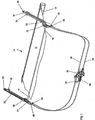
- the perspective view of the cover device 10 according to Figure 1 shows a in a winding cassette 14 on a (not shown) Covering or roller blind web 12 which can be rolled up and which is coupled with its end section which can be pulled out of the winding cassette 14 to a pull rod 16 which runs essentially parallel to the winding shaft or to the longitudinal extent of the winding cassette 14.
- the pull rod 16 is linearly positively guided with its two opposite end sections in two parallel guide rails 18, 20.
- the two guide rails 18, 20 are preferably arranged in the D-pillars, which adjoin, for example, a tailgate of a passenger car.
- displaceable carriers 32, 28 are guided in a longitudinally displaceable manner on corresponding guide slots 74, 76, as can be seen in the different FIGS Figures 2 to 4 driver positions shown.
- the guide rail is essentially straight.
- a curved guide rail course for example adapted to the vehicle geometry, is also within the scope of the invention.
- the Figures 2 to 4 show the guide rail 20 from the inside, that is seen from the roller blind 12.
- the traction means 38 which is designed as an actuating cable and is mechanically operatively connected to a gear motor 34 via a cable drum 36, is connected to an end section of the guide rail 20 via two hose sockets 44, 46.
- the core of the actuating cable 38 runs without guidance over a deflecting roller 50 which is rotatably mounted on the opposite end section of the guide rail 20, so that the core of the actuating cable is divided into an upper strand 52 and a lower strand 54 in the region of the guide rail 20.
- the second driver 28 is coupled, which is fixed within the guide slot 76 on the guide rail 20, while the first driver 32 is fixed on the upper cable pull strand 52 and the upper guide slot 74.
- the geometry of the guide rail 20 and the design and arrangement of guide slots 74, 76 and drivers 26, 28, 30, 32 is such that the two drivers 28, 32 and 26, 30 guided on a common guide rail 20 can be pushed past one another without hindrance.
- FIG 2 the driving movement that can be exercised by the second driver 28 on the pull rod 16 is outlined.
- a projection 70 of the driver 28, which is formed with a receptacle 72 comes into contact with the positively guided pull rod 16, so that as a result of exertion of a pull on the cable pull strand 54, the driver 28 and the pull rod 16 in operative connection move to the left in the direction of the end position of the pull rod 16 will.
- This end position of the pull rod is, for example, in Figure 3 shown.
- the pawl 24 is reached when the in Figure 3 indicated end position of the pull rod 16 either by gravity or by means of a spring action returns to its locking position, in which the pull rod 16 comes to rest in a convexly curved receptacle 60 of the undercut 58 of the pawl 24 and there also, inter alia, by the curvature 60 provided on the contour of the pull rod 16 in the vertical direction, that is to say is fixed perpendicular to the longitudinal extent of the guide rails 18, 20.
- the second driver 28 acting on the pull rod 16 and its projection 70 having the pull rod receptacle 72 are designed in such a way that the driver 28 or its projection 70 come into operative connection in the axial direction to the pull rod 16 outside a region with which the pull rod 16 connects with the Start slope 64 of the pawl 24 comes into contact position. It is thereby achieved in particular that the second driver 28, 26 can be inserted or immersed in an area which lies between the locking member 24, 22 and the associated guide rail 18, 20.
- the first cable 32 coupled to the upper cable pull strand 52, has on its lower and the corner section facing the locking member 24 an extension or projection 68 which extends essentially perpendicular to the guide rail plane and which has an inclined surface 66 which is in operative connection with the inclined surface 62 of the pawl 24 and is coordinated therewith.
- the pawl is located as in Figure 3 As an example, in its locking position and if the driver 32 is pulled further in the direction of the pivot axis 56 of the pawl 24 as a result of a tensile load on the cable strand 52, the locking member 24 is inserted into the locking element 24 as a result of the sloping surfaces 66, 62 which come into contact with one another Figure 4 shown release or release position raised, in which the pull rod 16 and the roller blind 12 due to the spring motor provided in the winding cassette 14 from the in Figure 3 shown end position, for example, can be automatically transferred to an intermediate position, such as a comfort position.
- the inclined surfaces provided on the pawl 24, namely the inclined surface 62 and the run-on bevel 64, can be arranged offset with respect to one another in relation to the axial direction of the pull rod 16 or the pivot axis 56. It is particularly advantageous here if the inclined surface 62 is arranged closer to the guide rail than the run-on bevel 64. In particular, it is provided that the two starting bevels 64 or inclined surfaces 62, which are in operative connection with the pull rod 16 or with the inclined surface 66 of the driver 32, have a different inclined position.
- the inclined surface 62 which is in operative connection with the first driver 32 is designed to be somewhat steeper than the run-on slope 64, so that when the driver 32 initiates transfer into the release or release position, the pawl 24 has a somewhat larger lifting or pivoting movement executes as if it is only temporarily raised due to the transfer of the tie rod 16 into the end position. This can ensure that the push rod 16 can be brought into a comfort position, for example, in a contact-free manner with respect to the end section of the pawl 24 tapering downwards.
- the crossed arrangement of the actuating cable 38 which is articulated on the two guide rails 18, 20 and is designed to be continuous and closed, is important.
- the upper pull cord 52 coupled to the driver 32 is connected via an in Figure 2 top of the hose to the in Figure 1 Coupled guide rail 20 shown on the left.
- the hose holder 46 is connected directly to the hose holder 40, this lower hose holder and the one running in the area of the associated guide rail 18, here not shown strand of the actuating cable is coupled to the driver 30.
- This strand of the actuating cable runs via the deflection 48 via the driver 26 and the hose socket 42 to the cable drum 36 and from there to the hose socket 44, to the cable pull cable 54 and ultimately to the driver 28 of FIG Figure 1 Guide rail 20 shown on the left.
- the actuating cable 38 is also provided adjacent to the cable drum 36 with a cable length adjusting device 80, which can automatically compensate for an elongation or dilation of the cable that occurs due to operation, so that any system or cable loops in the actuating cable can be eliminated.
- the deflection 48, 50 Because of the deflection 48, 50 present on both guide rails 18, 20, it is also sufficient for bidirectional adjustment of all the drivers 26, 28, 30, 32 to provide the force transmission between the adjustment drive 34 only via a traction means 38.
- the deflection 48, 50 namely causes the driver 32 in the illustration according to FIG Figure 2 to the left and the driver 28 is shifted to the right.
- the adjustment drive 34 and the associated cable drum 36 are reversed, the movement is reversed by exerting a corresponding pulling movement on the other cable pull strand 54 provided on the guide rail 20.
- Figure 5 shows a further embodiment of the covering device, wherein also here, as compared to the illustration according to Figure 1 two guide rails 20, 18 are provided for the positive guidance of at least two drivers 108, of which in Figure 5 only one is shown.
- the driver 108 is between the two in Figure 5 shown end positions, at the lower and at the upper end of the guide rail with the aid of the cable pull 102.
- the driver 108 and the pull rod 16 are detachably coupled to one another.
- the driver 108 can have an undercut receptacle for the pull rod 16, so that with the aid of the driver 108, the cover sheet 12 can be closed and pulled out of its winding shaft.
- the opening movement for the cover sheet takes place in that the driver 108 from the in Figure 5 lower end position is shifted into the higher position.
- This movement is further supported by a spring element or a corresponding spring motor typically arranged in the region of the winding shaft, so that an automatic release of the pull rod 16 from the driver 108 can be prevented.
- the embodiment differs according to Figure 5 from that according to Figure 1 in that, instead of a single cable 38, two separate cables 102, 104 are now provided, each of which provides a translatory adjustment movement between the drive 34 and the drivers 108 sliding along the parallel guide rails 18, 20.
- Both cable pulls 102, 104 or cable pull strands are each equipped with a cable length adjustment device 100, 110, which is supported at one end on the housing of the cable drum housing 106 coupled to the drive 34.
- the in Figure 5 The inner cable (not explicitly shown) of the cable pulls 102, 104 runs through the cable length adjusting devices 100, 110, while the associated outer cable is connected to a component of the cable length adjusting device 100, 110 that can be pulled out in the axial direction.
- the automatically operating rope length adjustment 100, 110 effects a "virtual" extension of the outer hose surrounding the inner cable, so that the rope loose that occurs can be automatically compensated for without the intervention of a user.
- both actuating cables 102, 104 are always held under a pretension, so that a synchronous drive of both actuating cables 102, 104 and with them a synchronous movement of the drivers 108 coupled to them can always be guaranteed. Any tilting or skewing of the pull rod 16 can thus be counteracted.
- both actuation cables 102, 104 which are designed independently of one another, to a common cable drum 106 which, with respect to its axis of rotation, has axially spaced or axially adjacent sections for receiving a cable cable 102, 104 each.
- a synchronous movement of the two drivers 108 guided on the guide rails 18, 20 can be made available in a simple manner by means of a single drive 34.
Abstract
Description
Die Erfindung betrifft eine Laderaumabdeckvorrichtung gemäß dem Oberbegriff des Anspruchs 1.The invention relates to a loading space covering device according to the preamble of claim 1.
Derartige Schutzvorrichtungen für den Innenraum eines Kraftfahrzeugs sind beispielsweise aus der
In jedem Führungsprofil ist jeweils ein als Kupplungsglied dienender Mitnehmerschlitten linear beweglich gelagert. Die beiden Mitnehmerschlitten eines der Führungsprofile sind dabei mittels einer Antriebsvorrichtung synchron zueinander in dem jeweiligen Führungsprofil beweglich. Als Übertragungsmittel für die Mitnehmerschlitten dienen biegeelastische, zug- und drucksteife Zahnstangen. Es können jedoch auch Bowdenzüge, Gewindewellen, Seil- oder Riementriebe vorgesehen werden. Die Synchronisation der Mitnehmerschlitten erfolgt mittels einer elektronischen Steuerung über zwei getrennte elektrische Antriebsmotoren für beide Seiten der Laderaumabdeckung.In each guide profile, a driver slide serving as a coupling member is mounted such that it can move linearly. The two carrier slides of one of the guide profiles can be moved in synchronism with one another in the respective guide profile by means of a drive device. Bending-elastic, tension and compression-resistant racks serve as transmission means for the driving slides. However, Bowden cables, threaded shafts, rope or belt drives can also be provided. The carriage is synchronized by means of an electronic control via two separate electric drive motors for both sides of the load compartment cover.
Eine derartige Synchronisation ist verhältnismäßig teuer in der Herstellung und erfordert einen hohen Montageaufwand.Such synchronization is relatively expensive to manufacture and requires a lot of assembly.
Die getrennte Anordnung zweier elektrischer Antriebsmotoren erfordert zudem eine aufwendige Justage und Kalibrierung des Systems. Weiterhin wird durch die Verwendung zweier separater elektrischer Antriebsmotoren entsprechender Bauraum im Kraftfahrzeug benötigt, der zu einer Gewichtserhöhung des Fahrzeugs beiträgt.The separate arrangement of two electric drive motors also requires complex adjustment and calibration of the system. Furthermore, by using two separate electric drive motors appropriate space in the motor vehicle is required, which contributes to an increase in weight of the vehicle.
Zudem ist die Kraftübertragung zwischen Antriebsmotor und Mitnehmern mittels zug- und drucksteifen Kraftübertragungsmitteln, wie etwa innerhalb starrer Führungsrohre verlaufender Steigungskabel nur bedingt an unterschiedliche Einbaumaße verschiedener Kraftfahrzeugtypen oder-Modelle anpassbar. Solch biegesteife Führungs- und Kraftübertragungsmittel beanspruchen ein hohes Maß an Bauraum und sind aufgrund ihres sperrigen unflexiblen Aufbaus bei der Montage nur recht schwierig handhabbar.In addition, the power transmission between the drive motor and drivers can be adapted to different installation dimensions of different motor vehicle types or models only to a limited extent by means of tension and pressure-resistant force transmission means, such as, for example, riser cables running within rigid guide tubes. Such rigid guide and power transmission means take up a large amount of space and are difficult to handle due to their bulky, inflexible structure during assembly.
Ein solch sperriger interner Aufbau eines Antriebssystems macht sich zudem beim Transport von einem Automobilzulieferer zum Endkunden, dem Automobilhersteller, als nachteilig bemerkbar. Denn der sperrige Aufbau eines solchen Antriebssystems erzwingt einen recht aufwendigen und somit kostenintensiven Transport zwischen der Fertigungsstätte des Antriebsmoduls beim Zulieferer und der Endmontage des Kraftfahrzeuges beim Automobilhersteller.Such a bulky internal structure of a drive system is also noticeable when it is transported from an automotive supplier to the end customer, the automobile manufacturer. Because the bulky structure of such a drive system forces a very complex and thus costly transport between the manufacturing site of the drive module at the supplier and the final assembly of the motor vehicle at the automobile manufacturer.
Aus der
Aus der
Aus der
Weitere Abdeck- und Rollovorrichtungen sind aus der
Der vorliegenden Erfindung liegt die Aufgabe zugrunde, eine Laderaumabdeckvorrichtung für den Kraftfahrzeuginnenraum zur Verfügung zu stellen, die eine möglichst platzsparende und flexible Anordnung im Kraftfahrzeug ermöglicht und auch bei längerem Einsatz einwandfrei verfahrbar ist.The present invention is based on the object of providing a loading space covering device for the motor vehicle interior which enables a space-saving and flexible arrangement in the motor vehicle which is as space-saving as possible and which can be moved smoothly even after prolonged use.
Die der Erfindung zugrunde liegende Aufgabe wird mittels einer Laderaumabdeckvorrichtung gemäß Anspruch 1 gelöst. Weitere vorteilhafte Ausführungsformen der Erfindung sind in den jeweiligen Unteransprüchen angegeben.The object on which the invention is based is achieved by means of a loading space covering device according to claim 1. More beneficial Embodiments of the invention are specified in the respective subclaims.
Danach betrifft die Erfindung eine Laderaumabdeckvorrichtung für den Kraftfahrzeuginnenraum mit einer flächig aufspannbaren, auf einer drehbar gelagerten Wickelwelle aufrollbaren Abdeck- oder Rollobahn, an der eine Zugstange angeordnet ist, die mit ihren gegenüberliegenden Endabschnitten zwischen zwei im Wesentlichen parallel zueinander verlaufenden Führungsschienen zwangsgeführt ist und die mit einem Verstellantrieb koppelbar ist. Zur Kopplung der Zugstange mit dem Verstellantrieb ist an jeder Führungsschiene zur Überführung der Zugstange von einer Ausgangs- in eine Endstellung ein lediglich ein einziger im bisherigen Kontext als zweiter Mitnehmer bezeichneter Mitnehmer vorgesehen. Dieser Mitnehmer kann zur unidirektionalen Kopplung zwischen Antrieb und Zugstange Verwendung finden, insbesondere, um die Zugstange in eine Endstellung zu überführen. Der zweite Mitnehmer kann aber auch fest oder lösbar mit der Zugstange gekoppelt werden, so dass eine bidirektionale Bewegung dieses Mitnehmers auch unmittelbar auf die Zugstange übertragen werden kann. Prinzipiell ist diese, lediglich einen einzigen Mitnehmer je Führungsschiene aufweisende Ausführungsform bereits dazu geeignet, die Zugstange bidirektional, d. h. sowohl in ihre Ausgangs- als auch in ihre Endstellung und zurück zu überführen. Beispielsweise kann hierzu vorgesehen sein, die mit der Abdeckbahn verbundene Zugstange lösbar am Mitnehmer anzuordnen, diese beispielsweise am Mitnehmer einzuclipsen oder mittels formflüssiger Verbindungsmittel, etwa mit Hilfe einer am Mitnehmer ausgebildeten Hinterschneidung am Mitnehmer zu fixieren. Die Befestigung von Zugstange und Mitnehmer ist derart ausgebildet, dass der Mitnehmer im Wesentlichen eine Auszugsbewegung auf die Zugstange ausübt, während ein im Bereich der Wickelwelle angeordneter Federmechanismus, etwa ein Federmotor eine entgegenwirkende Rückstellkraft auf die Zugstange ausübt. Der Mitnehmer einer jeden Führungsschiene ist dabei mittels eines flexibel ausgebildeten Zugmittels in Form eines Seilzuges, an den Verstellantrieb gekoppelt. Dem Zugmittel, welches eine translatorische Kopplung zwischen dem Verstellantrieb und dem entlang der Schiene verfahrbaren Mitnehmer zur Verfügung stellt ist eine Längennachstellvorrichtung zugeordnet. Diese dient der Kompensation etwaiger betriebsbedingt auftretender Längungen oder einer Dilatation des Zugmittels. Ist das Zugmittel als Seilzug ausgebildet, so unterliegt dessen als Seillitze ausgebildeter Innenzug im fortwährenden Gebrauch aufgrund von Alterungsprozessen und fortwährender Belastung einer Längung, die einige Millimeter wenn nicht gar Zentimeter betragen kann. Eine solche Längung führt zu einer Systemlosen oder Seillosen im Kraftübertragungsstrang, welche nachteilige Auswirkungen auf den gesamten Verstellmechanismus haben kann. Wird die System- oder Seillose nicht kompensiert, so wird diese zu Beginn einer einsetzenden Verstellbewegung zunächst aufgebraucht, bevor über das Zugmittel eine Verstellbewegung auf den Mitnehmer übertragen werden kann. Mittels der Längennachstellvorrichtung kann eine etwaige auftretende System- oder Seillose kompensiert werden, so dass der Seilzug in jeder denkbaren Betriebsstellung stets unter einer erforderlichen Spannung steht, so dass mit Einsetzen einer vom Stellantrieb initiierten Drehbewegung diese unmittelbar auf eine entsprechende Verstellbewegung der Mitnehmer übertragen werden kann. Bei der Ausgestaltung des Zugmittels als Betätigungszug mit einem in einem Außenschlauch geführten Innenzug bewirkt die Längennachstellvorrichtung eine der betriebsbedingten Längung des Innenzugs entsprechende "virtuelle" Verlängerung des den Innenzug umhüllenden Schlauchs. Eine Längennachstellvorrichtung weist typischerweise zwei in Axialrichtung, d.h. in Richtung der Seilzugerstreckung gegeneinander verschiebbare Komponenten, etwa eine Hülse und einen in einer Hülse geführten Fortsatz auf, wobei beide Komponenten mit der Hülle oder dem Schlauch des Betätigungszuges verbunden sind.According to the invention, the invention relates to a loading space covering device for the motor vehicle interior with a covering or blind sheet that can be stretched flatly and rolled up on a rotatably mounted winding shaft, on which a pull rod is arranged, which is positively guided with its opposite end sections between two essentially parallel guide rails and that with an adjustment drive can be coupled. To couple the pull rod to the adjustment drive, only one single driver, referred to in the previous context as the second driver, is provided on each guide rail for transferring the pull rod from an initial position to an end position. This driver can be used for unidirectional coupling between the drive and the pull rod, in particular to transfer the pull rod into an end position. The second driver can also be fixed or detachably coupled to the pull rod, so that a bidirectional movement of this driver can also be transmitted directly to the pull rod. In principle, this embodiment, which has only one driver per guide rail, is already suitable for transferring the pull rod bidirectionally, ie both into its starting position and into its end position and back. For example, it can be provided for this purpose that the pull rod connected to the cover sheet is releasably arranged on the carrier, can be clipped on to the carrier, for example, or fixed to the carrier by means of a fluid connection means, for example with the aid of an undercut formed on the carrier. The tie rod and driver are fastened in such a way that the driver essentially exerts a pull-out movement on the tie rod, while a spring mechanism, for example a spring motor, arranged in the region of the winding shaft exerts an opposing restoring force on the tie rod. The driver of each guide rail is coupled to the adjustment drive by means of a flexible traction device in the form of a cable pull. The A traction device, which provides a translatory coupling between the adjustment drive and the driver that can be moved along the rail, is assigned a length adjustment device. This is used to compensate for any elongations that occur during operation or for dilation of the traction device. If the traction means is designed as a cable pull, its inner cable, which is designed as a rope strand, is subject to constant elongation during use due to aging processes and constant stress, which can be a few millimeters if not centimeters. Such elongation leads to a systemless or rope-less in the power transmission train, which can have an adverse effect on the entire adjustment mechanism. If the system or rope lots are not compensated, they are used up at the beginning of an adjustment movement that begins before an adjustment movement can be transmitted to the driver via the traction means. Any system or rope loose that occurs can be compensated for by means of the length adjustment device, so that the cable pull is always under a required tension in every conceivable operating position, so that when a rotary movement initiated by the actuator is used, this can be transferred directly to a corresponding adjustment movement of the drivers. In the configuration of the traction means as an actuating cable with an inner cable guided in an outer hose, the length adjustment device effects a "virtual" extension of the hose enveloping the inner cable corresponding to the operational lengthening of the inner cable. A length adjustment device typically has two components which can be displaced relative to one another in the axial direction, ie in the direction of the cable extension, for example a sleeve and an extension guided in a sleeve, both components being connected to the sleeve or the hose of the actuating cable.
Der Fortsatz und die den Fortsatz aufnehmende Hülse weisen typischerweise einander korrespondierende Rastelemente auf oder sind mit separaten Rastelementen gekoppelt, die ein Auseinanderziehen, d. h. ein axiales Verlängern der Längennachstellvorrichtung ermöglichen, aber eine entgegengerichtetes Zusammenschieben der beiden Komponenten verhindern.The extension and the sleeve receiving the extension typically have mutually corresponding locking elements or are with separate locking elements coupled, which pull apart, that is, an axial lengthening of the length adjustment device, but prevent the opposite pushing together of the two components.
Das Auseinanderziehen der Längennachstellvorrichtung, bzw. das in Axialrichtung gerichtete Herausbewegen des Fortsatzes aus einer Hülse heraus kann unter Einwirkung einer Feder erfolgen, so dass bei Auftreten einer Systemlosen, etwa in Folge einer betriebsbedingten Längung des Innenzuges, die beiden Komponenten der Längennachstellvorrichtung selbsttätig um eine vorgegebenes Maß auseinander bewegt werden. Durch eine entsprechende Längung des den Innenzug umgebenden Schlauchs kann die System- oder Seillose kompensiert werden, so dass der gesamte Betätigungszug wieder unter der erforderlichen Spannung steht.The pulling apart of the length adjustment device or moving the extension in the axial direction out of a sleeve can take place under the action of a spring, so that when systemless occurs, for example as a result of an operation-related lengthening of the inner cable, the two components of the length adjustment device automatically by a predetermined amount Be moved apart. The system or rope-less can be compensated for by a corresponding elongation of the hose surrounding the inner cable, so that the entire operating cable is again under the required tension.
Es ist ferner vorgesehen, dass auch die beiden, an unterschiedlichen Führungsschienen verfahrbaren Mitnehmer über das Zugmittel unmittelbar miteinander gekoppelt sind. Die Kopplung der beiden Mitnehmer über das Zugmittel ist hierbei derart, dass bei einer Betätigung des Verstellantriebs die Zugmittel eine zueinander gleichgerichtete und synchrone Bewegung ausführen.It is further provided that the two drivers that can be moved on different guide rails are also directly coupled to one another via the traction means. The coupling of the two drivers via the traction means is such that when the adjustment drive is actuated, the traction means execute a synchronous movement which is aligned with one another.
Durch das Vorsehen eines flexibel ausgebildeten Zugmittels kann in vorteilhafter Weise eine universelle, an unterschiedlichste Einbaumaße und Einbauanforderungen anpassbare Verstelleinrichtung für ein Abdeckrollo zur Verfügung gestellt werden, welches mit lediglich einem einzigen Verstellantrieb auskommt. Es ist hierbei insbesondere vorgesehen, dass der zweite Mitnehmer lediglich eine unidirektionale Verstellbewegung auf die Zugstange, nämlich in Richtung zu deren Endstellung ausübt. Zum Öffnen der Abdeckvorrichtung, insbesondere zum Herausführen der Zugstange aus ihrer Endstellung ist ein im Bereich der Wickelwelle, innerhalb einer Wickelkassette angeordneter Federmotor vorgesehen.The provision of a flexible traction means can advantageously provide a universal adjustment device for a cover roller blind that can be adapted to a wide variety of installation dimensions and installation requirements, and which requires only a single adjustment drive. In particular, it is provided that the second driver only exerts a unidirectional adjustment movement on the pull rod, namely in the direction of its end position. In order to open the cover device, in particular to lead the pull rod out of its end position, a spring motor is provided in the region of the winding shaft, within a winding cassette.
Erfindungsgemäß ist das flexible, als Seilzug ausgebildete Zugmittel an einem stirnseitigen Endabschnitt der Führungsschienen angelenkt und an einem dem Endabschnitt gegenüberliegenden Abschnitt über eine Umlenkung geführt. Mittels der Umlenkung wird die Seele des Seilzugs von einer am Endabschnitt der Führungsschiene vorgesehenen Schlauchfassung bis zur Umlenkrolle und von dort wieder zurück zu einer weiteren, am Endabschnitt der Führungsschiene vorgesehenen Schlauchfassung geführt.According to the invention, the flexible traction means designed as a cable is articulated on an end section of the guide rails and guided on a section opposite the end section via a deflection. By means of the deflection, the core of the cable is guided from a hose socket provided at the end section of the guide rail to the deflection roller and from there back to a further hose socket provided at the end section of the guide rail.
An jeden der beiden Seilzugstränge einer Führungsschiene ist jeweils ein Mitnehmer angebunden, der zumindest zum Überführen der an der Führungsschiene zwangsgeführten Zugstange in deren Endstellung vorgesehen ist. Die Ausbildung eines flexiblen Seilzugs als Bewegungs- oder Kraftübertragungsmittel vom Verstellantrieb auf die Mitnehmer und somit auf die Zugstange ist gegenüber drucksteifen Zug-Druckmitteln, wie etwa Gewindespindeln, Zahnstangen oder Steigungskabeln von Vorteil, da infolge der Umlenkung eine bidirektionale Bewegung der Mitnehmer bereits durch Einleitung einer Zugkraft auf einen der Seilzugstränge erfolgen kann.A driver is connected to each of the two cable pull strands of a guide rail and is provided at least for transferring the pull rod which is positively guided on the guide rail into its end position. The formation of a flexible cable as a movement or force transmission means from the adjustment drive to the drivers and thus to the pull rod is advantageous compared to compression-resistant tension-pressure media, such as threaded spindles, racks or riser cables, as a result of the deflection, a bidirectional movement of the drivers by initiation of a Pulling force can take place on one of the cable pull strands.
Nach einer vorteilhaften Weiterbildung der Erfindung ist vorgesehen, das Zugmittel als geschlossenen umlaufenden Seilzug auszubilden, an welchem die mit der Zugstange in Wirkverbindung stehenden Mitnehmer einer jeden Führungsschiene gekoppelt ist, wobei dieser zwischen den Schienen vorzugsweise über Kreuz verlaufende Seilzug eine Kopplung beider Mitnehmer an den gemeinsamen Verstellantrieb zur Verfügung stellt. Hierdurch kann eine synchrone Bewegung der an den parallel verlaufenden Führungsschienen geführten Mitnehmer zur Verfügung gestellt werden.According to an advantageous development of the invention, it is provided that the traction means is designed as a closed peripheral cable, to which the drivers of each guide rail that are operatively connected to the pull rod are coupled, with this cable pull, which preferably crosses the rails, coupling both drivers to the common one Actuator provides. As a result, a synchronous movement of the drivers guided on the parallel guide rails can be made available.
Anstelle einer Ausbildung eines einzigen über Kreuz verlaufenden Seilzugs können auch zwei getrennte Seilzüge vorgesehen werden, welche einerseits an je einem Mitnehmer und andererseits an einem gemeinsamen Verstellantrieb für beide Seilzüge angelenkt sind.Instead of forming a single cable pull running crosswise, two separate cable pulls can also be provided, which are articulated on the one hand on each driver and on the other hand on a common adjustment drive for both cable pulls.
Von Vorteil ist weiterhin die Kopplung zwischen dem Verstellantrieb und dem Zugmittel mittels einer Seiltrommel. Die Seiltrommel, welche typischerweise mit einem Getriebemotor in Wirkverbindung steht, bewirkt, dass die Seele des Seil-oder Betätigungszugs in beide Richtungen, bezogen auf den die Seele umschließenden äußeren Schlauch, verschoben werden kann.The coupling between the adjustment drive and the traction means by means of a cable drum is also advantageous. The cable drum, which is typically in operative connection with a geared motor, has the effect that the core of the cable or actuating cable can be displaced in both directions with respect to the outer hose surrounding the core.
Bei einer Ausgestaltung mit zwei einzelnen Seilzügen ist es ferner von Vorteil, jeden dieser Seilzüge mittels einer einzigen Seiltrommel an den gemeinsamen Antrieb zu koppeln. Diese Seiltrommel kann dabei als zweigeteilte Seiltrommel ausgebildet sein mit axial voneinander beabstandeten und zueinander drehfest angeordneten Seiltrommelabschnitten, welche zur Aufnahme je eines Seilzuges ausgebildet sind.In an embodiment with two individual cable pulls, it is also advantageous to couple each of these cable pulls to the common drive by means of a single cable drum. This cable drum can be designed as a two-part cable drum with axially spaced and non-rotatably arranged cable drum sections, which are designed to receive a cable.
Die beiden Seiltrommelabschnitte können dabei bezogen auf die Drehachse der Seiltrommel axial voneinander beabstandet oder axial nebeneinander zu liegen kommend angeordnet sein. Auf diese Art und Weise kann auf beide Seilzüge bei Betätigung des Verstellantriebes eine synchrone Bewegung aufgeübt werden.The two cable drum sections can be arranged axially spaced from one another in relation to the axis of rotation of the cable drum or can be arranged to lie axially next to one another. In this way, a synchronous movement can be exercised on both cables when the adjustment drive is actuated.
Von Vorteil ist es dabei, wenn jedem der beiden Seilzüge eine gesonderte Längennachstellvorrichtung zugeordnet ist. Dabei kann insbesondere vorgesehen sein, die Längennachstellvorrichtung unmittelbar am Seiltrommelgehäuse anzuordnen oder in dieses zu integrieren.It is advantageous if each of the two cables is assigned a separate length adjustment device. In particular, provision can be made for the length adjustment device to be arranged directly on the cable drum housing or to be integrated therein.
Die Laderaumbdeckvorrichtung ist zum Abdecken des Laderaums eines Kraftfahrzeugs, insbesondere eines Personenkraftwagens vorgesehen. Die Laderaumabdeckvorrichtung weist eine auf- und abrollbare Abdeckbahn, wie etwa eine Rollobahn auf, die auf eine drehbar gelagerte, innerhalb einer Wickelkassette angeordnete Wickelwelle aufrollbar ist. An dem aus der Wickelkassette ausziehbaren Endabschnitt der Abdeckbahn ist eine sich quer oder senkrecht zur Ausrollrichtung verlaufende Zugstange angeordnet, die ihrerseits mit ihren gegenüberliegenden Endabschnitten zwischen den Führungsschienen zwangsgeführt und im Bereich der Führungsschiene mit einem Verstellantrieb koppelbar ist. Nach einer bevorzugten Ausführungsform der Erfindung ist ein Verriegelungsglied vorgesehen, welches wahlweise in eine Verriegelungsstellung oder Lösestellung überführt werden kann.The loading space covering device is provided for covering the loading space of a motor vehicle, in particular a passenger car. The loading space covering device has a cover sheet that can be rolled up and unrolled, such as a roller blind sheet, which can be rolled up onto a rotatably mounted winding shaft arranged within a winding cassette. On that from the Extendable end section of the cover sheet of the winding cassette is arranged a pull rod extending transversely or perpendicular to the rolling direction, which in turn is positively guided with its opposite end sections between the guide rails and can be coupled to an adjustment drive in the region of the guide rail. According to a preferred embodiment of the invention, a locking member is provided, which can optionally be transferred to a locking position or release position.
In seiner Verriegelungsstellung ist das Verriegelungsglied dazu ausgebildet, die an der Führungsschiene zwangsgeführte Zugstange in einer Endstellung zu fixieren. Es kann zumindest ein erster entlang der Führungsschiene verfahrbarer Mitnehmer vorgesehen sein, der zumindest dazu ausgebildet ist, das Verriegelungsglied von seiner Verriegelungsstellung in die Lösestellung zu überführen, in welcher das Verriegelungsglied die Zugstange freigibt.In its locking position, the locking member is designed to fix the pull rod which is positively guided on the guide rail in an end position. At least one first driver which can be moved along the guide rail can be provided, which is at least designed to transfer the locking member from its locking position into the release position in which the locking member releases the pull rod.
Der entlang der Führungsschiene verfahrbare Mitnehmer dient somit nicht ausschließlich, wie im Stand der Technik üblich, einer Kopplung zwischen dem Verstellantrieb und der Zugstange, sondern er kann im Rahmen der Erfindung auch als Entriegelungsglied zum Entriegeln und Freigeben der Zugstange dienen.The driver which can be moved along the guide rail thus not only serves, as is customary in the prior art, to couple between the adjusting drive and the pull rod, but it can also serve as an unlocking member for unlocking and releasing the pull rod within the scope of the invention.
Der zumindest erste Mitnehmer ist beim Entriegelungsvorgang in unmittelbarer Wirkverbindung mit dem Verriegelungsglied. Somit sind zum Entriegeln der Zugstange lediglich zwei miteinander in Wirkverbindung tretende mechanische Komponenten, nämlich das Verriegelungsglied selbst und der erste Mitnehmer erforderlich. Der erste Mitnehmer ist dabei dazu vorgesehen, infolge einer entlang der Führungsschiene verlaufenden Verstellbewegung derart mit dem Verriegelungsglied zusammen zu wirken, dass dieses von der Verriegelungsstellung in die Entriegelungs- oder Lösestellung überführt wird.The at least first driver is in direct operative connection with the locking member during the unlocking process. Thus, only two mechanical components that are in operative connection with one another, namely the locking member itself and the first driver, are required to unlock the pull rod. The first driver is intended to cooperate with the locking member as a result of an adjustment movement running along the guide rail in such a way that the locking member is transferred from the locking position into the unlocking or release position.
Dieser Lösemechanismus ist daher besonders wartungsarm und kaum störanfällig. Zudem kann der Entriegelungsmechanismus besonders kostengünstig implementiert werden, da hierzu lediglich ein besonders ausgestalteter erster Mitnehmer an einer ohnehin vorhandenen Führungsschiene geführt werden muss.This release mechanism is therefore particularly low-maintenance and hardly susceptible to failure. In addition, the unlocking mechanism can be implemented in a particularly cost-effective manner, since for this purpose only a specially designed first driver has to be guided on an already existing guide rail.
Die in einer Wickelkassette aufgenommene Wickelwelle der Abdeck- oder Rollobahn ist mit einem Federmechanismus, vorzugsweise mit einem Federmotor ausgestattet, wobei das Abrollen bzw. Aufspannen der Abdeckbahn gegen die Federkraft erfolgt. Hierdurch kann ein zumindest bereichsweises selbsttätiges Aufrollen der Abdeckbahn erfolgen, wenn das Verriegelungsglied infolge der Verfahrbewegung des ersten Mitnehmers die Zugstange aus der Endstellung freigibt. Es ist hierbei insbesondere vorgesehen, dass die Abdeckbahn oder das Abdeckrollo infolge einer Entriegelung aus der Endstellung in eine sogenannte Komfortstellung überführt werden kann, in welcher der beispielsweise unter der Abdeckbahn befindliche Laderaum eines Kraftfahrzeugs zumindest bereichsweise zum Be- oder Entladen freigegeben wird.The winding shaft of the covering or roller blind web accommodated in a winding cassette is equipped with a spring mechanism, preferably with a spring motor, the covering web being unrolled or stretched against the spring force. As a result, the cover sheet can be rolled up automatically at least in some areas if the locking member releases the pull rod from the end position as a result of the movement of the first driver. In particular, it is provided that the cover sheet or the cover roller blind can be transferred from the end position into a so-called comfort position in which the load space of a motor vehicle, for example, located under the cover sheet is released for loading or unloading at least in regions.
Nach einer ersten Weiterbildung der Erfindung ist der erste Mitnehmer mit dem Verstellantrieb gekoppelt. Dies hat den Vorteil, dass zum Entriegeln der Zugstange aus ihrer Endstellung kein separater Stellmotor erforderlich ist, sondern dass der ohnehin zum Verstellen der Abdeckbahn vorhandene Verstellantrieb universell auch zum Initiieren einer Entriegelung Verwendung finden kann. Auf diese Art und Weise kann die gesamte Laderaumabdeckvorrichtung mit lediglich einem einzigen Verstellantrieb verwirklicht werden.According to a first development of the invention, the first driver is coupled to the adjustment drive. This has the advantage that no separate servomotor is required to unlock the pull rod from its end position, but that the adjustment drive which is present anyway for adjusting the cover sheet can also be used universally for initiating an unlocking. In this way, the entire loading space covering device can be realized with only a single adjustment drive.
Nach einer weiteren Ausführungsform der Erfindung ist ein zweiter, ebenfalls entlang der Führungsschiene verfahrbarer Mitnehmer vorgesehen, der zumindest dazu ausgebildet ist, die Zugstange entlang ihrer Zwangsführung in die Endstellung zu überführen. Dieser zweite Mitnehmer wirkt somit unmittelbar auf die zwangsgeführte Zugstange ein, während der erste Mitnehmer für ein Zusammenwirken mit dem Verriegelungsglied vorgesehen ist. Der zweite Mitnehmer ist zumindest derart an der Führungsschiene gegenüber der Zugstange positioniert und ist auch derart ausgestaltet, sodass die Zugstange mittels dieses zweiten Mitnehmers zumindest in einer Richtung, nämlich entlang der Auszugsrichtung, entlang der Führungsschiene bewegt werden kann.According to a further embodiment of the invention, a second driver, likewise movable along the guide rail, is provided, which is at least designed to move the pull rod along its To bring positive control into the end position. This second driver thus acts directly on the positively guided pull rod, while the first driver is intended to interact with the locking member. The second driver is positioned at least in this way on the guide rail opposite the pull rod and is also designed such that the pull rod can be moved along the guide rail by means of this second driver at least in one direction, namely along the extension direction.
Nach einer weiteren vorteilhaften Ausführung der Erfindung ist vorgesehen, dass der erste und der zweite Mitnehmer unmittelbar mit dem Verstellantrieb gekoppelt sind. Die Kopplung des ersten und des zweiten Mitnehmers an der Führungsschiene ist dergestalt, dass die beiden Mitnehmer im Betrieb des Verstellantriebs zueinander entgegengerichtete Verstellbewegungen entlang der Führungsschiene ausführen.According to a further advantageous embodiment of the invention, it is provided that the first and the second driver are directly coupled to the adjustment drive. The coupling of the first and the second driver to the guide rail is such that the two drivers carry out opposing adjustment movements along the guide rail during the operation of the adjustment drive.
Bei aktiviertem Verstellantrieb bewegen sich die beiden entlang einer gemeinsamen Mitnehmerschiene vorgesehenen Mitnehmer aufeinander zu und/oder voneinander weg. Die Anbindung des ersten und des zweiten Mitnehmers an der Führungsschiene ermöglicht ein aneinander Vorbeiführen der Mitnehmer. Es ist hierbei insbesondere vorgesehen, dass die Mitnehmer an unterschiedlichen Seiten der Führungsschiene oder an derselben Seite der Führungsschiene, dann aber in unterschiedlicher Höhe daran gleitend gelagert sind. Die Anordnung der beiden Mitnehmer an derselben, beispielsweise der Abdeckbahn zugewandten Seite der Führungsschiene ermöglicht einen Bauraum einsparenden Aufbau der gesamten Abdeckvorrichtung, insbesondere im Bereich der vorzugsweise in einer D-Säule eines Kraftfahrzeugs unterzubringenden Führungsschiene.When the adjustment drive is activated, the two drivers provided along a common driver rail move towards and / or away from one another. The connection of the first and the second driver to the guide rail enables the drivers to be guided past one another. In particular, it is provided that the drivers are slidably mounted on different sides of the guide rail or on the same side of the guide rail, but then at different heights. The arrangement of the two drivers on the same side of the guide rail, for example facing the cover sheet, enables a space-saving construction of the entire cover device, in particular in the area of the guide rail which is preferably to be accommodated in a D-pillar of a motor vehicle.
Nach einer besonders vorteilhaften Ausgestaltung der Erfindung ist das Verriegelungsglied als schwenkbar gelagerte Sperrklinke mit einer Anlaufschräge ausgebildet. Diese Anlaufschräge wirkt beim Überführen der Zugstange in die Endstellung mit einem Zugstangenabschnitt derart zusammen, dass die Sperrklinke beispielsweise gegen die Schwerkraft oder gegen eine Federkraft aus ihrer Verriegelungsstellung zumindest zeitweise derart angehoben wird, dass die Zugstange ihrerseits in die vorgesehene Endstellung überführt werden kann, in welcher die Sperrklinke wieder ihre Verriegelungsstellung einnimmt und ein selbsttätiges Bewegen der Zugstange aus der Endstellung heraus verhindert.According to a particularly advantageous embodiment of the invention, the locking member is designed as a pivotably mounted pawl with a run-on slope. This start-up slope acts when the Pull rod into the end position together with a pull rod section in such a way that the pawl is at least temporarily lifted out of its locking position, for example against gravity or against a spring force, in such a way that the pull rod can in turn be transferred to the intended end position in which the pawl again assumes its locking position and prevents the drawbar from automatically moving out of the end position.
In ihrer Endstellung kommt die Zugstange dann beispielsweise an einer Hinterschneidung der Sperrklinke, welche sich vorzugsweise an die Anlaufschräge anschließt, zu liegen. Die Freigabe der Zugstange und damit der mit der Zugstange verbundenen Abdeckbahn erfolgt über eine Schwenkbewegung des Verriegelungsglieds in dessen Lösestellung. Dies kann entweder manuell oder durch den ersten Mitnehmer initiiert erfolgen.In its end position, the pull rod then comes to rest, for example, on an undercut of the pawl, which preferably adjoins the run-on slope. The release of the pull rod and thus the cover sheet connected to the pull rod takes place via a pivoting movement of the locking member in its release position. This can either be done manually or initiated by the first driver.
Nach einer Weiterbildung der Erfindung weist der erste Mitnehmer eine Schrägfläche auf, die mit einer korrespondierenden Schrägfläche des Verriegelungsglieds zusammenwirkt, sodass das Verriegelungsglied infolge einer entsprechenden Verstellbewegung entlang der Führungsschiene von der Verriegelungsstellung in die Lösestellung überführt wird. Die mit dem ersten Mitnehmer zusammenwirkende Schrägfläche des Verriegelungsglieds als auch dessen mit der Zugstange in Wirkverbindung tretende Anlaufschräge können zwar zusammenfallen.According to a further development of the invention, the first driver has an inclined surface which cooperates with a corresponding inclined surface of the locking member, so that the locking member is transferred from the locking position into the release position as a result of a corresponding adjustment movement along the guide rail. The inclined surface of the locking member interacting with the first driver, as well as its start-up bevel, which is in operative connection with the pull rod, can coincide.
Von Vorteil ist es jedoch, wenn die Schrägfläche des Verriegelungsglieds, welche mit einer korrespondierenden Schrägfläche des ersten Mitnehmers zusammenwirkt und die Anlaufschräge des Verriegelungsglieds, bezogen auf die Schwenkachse des Verriegelungsglieds zueinander axial versetzt ausgebildet sind. Hierbei ist insbesondere von Vorteil, wenn die Anlaufschräge und die Schrägfläche des Verriegelungsglieds unterschiedliche Winkel aufweisen, sodass insbesondere beim durch den ersten Mitnehmer initiierten Überführen des Verriegelungsglieds in die Lösestellung das Verriegelungsglied eine größere Schwenkbewegung ausführt, als wenn es durch das Überführen der Zugstange in deren Endstellung in die Lösestellung überführt wird.However, it is advantageous if the inclined surface of the locking member, which cooperates with a corresponding inclined surface of the first driver, and the starting bevel of the locking member are axially offset with respect to one another with respect to the pivot axis of the locking member. It is particularly advantageous here if the starting bevel and the inclined surface of the locking member have different angles, so that in particular when the locking member is initiated by the first driver in the Release position the locking member performs a greater pivoting movement than if it is transferred into the release position by moving the pull rod in its end position.
Dadurch, dass der erste Mitnehmer eine größere Verschwenkbewegung auf das Verriegelungsglied ausübt, kann die Zugstange bei einer durch den ersten Mitnehmer gehaltenen Lösestellung des Verriegelungsglieds reibungs- und berührungsfrei am Verriegelungsglied vorbeigeführt werden.Because the first driver exerts a greater pivoting movement on the locking member, the pull rod can be guided past the locking member without friction and contact when the locking member is in the released position.
Nach einer Weiterbildung der Erfindung ist vorgesehen, dass die am ersten Mitnehmer vorgesehene Schrägfläche als ein von der Führungsschienenebene weg weisender Vorsprung des Mitnehmers ausgebildet ist. Dieser sich im Wesentlichen senkrecht zur Schienenebene erstreckende Vorsprung ermöglicht, dass der erste Mitnehmer beim Überführen des Verriegelungsglieds in dessen Lösestellung zumindest abschnittsweise in einen Bereich zwischen dem Verriegelungsglied und der Führungsschiene hineinfahren kann.According to a development of the invention, it is provided that the inclined surface provided on the first driver is designed as a projection of the driver pointing away from the guide rail plane. This projection, which extends essentially perpendicular to the rail plane, enables the first driver to move at least in sections into an area between the locking member and the guide rail when the locking member is transferred into its release position.
Nach einer Weiterbildung der Erfindung ist vorgesehen, dass das Verriegelungsglied eine konvex gewölbte Aufnahme für die Zugstange aufweist, in welcher die Zugstange in ihrer Endstellung zu liegen kommt, insbesondere dann, wenn sich das Verriegelungsglied in seiner Verriegelungsstellung befindet. Die konvex gewölbte, dem Querschnittsprofil der Zugstange angepasste Aufnahme des Verriegelungsglieds unterstützt eine sichere und möglichst spielfreie Fixierung der Zugstange in ihrer Endstellung.According to a development of the invention, it is provided that the locking member has a convexly curved receptacle for the pull rod, in which the pull rod comes to rest in its end position, in particular when the locking member is in its locked position. The convexly curved receptacle of the locking member, which is adapted to the cross-sectional profile of the drawbar, supports a secure and play-free fixation of the drawbar in its end position.
Die konvex gewölbte Aufnahme des Verriegelungsglieds bewirkt hierbei insbesondere eine Fixierung der Zugstange hinsichtlich etwaiger Bewegungen senkrecht oder quer zur Längserstreckung der Führungsschiene.The convexly curved receptacle of the locking member in this case in particular fixes the pull rod with respect to any movements perpendicular or transverse to the longitudinal extension of the guide rail.
Nach einer Weiterbildung der Erfindung ist vorgesehen, dass das zweite Mitnehmerelement einen als Mitnehmeranschlag ausgebildeten Vorsprung aufweist, an welchem zumindest an der dem Verriegelungsglied zugewandten Seitenfläche eine Aufnahme ausgebildet ist. Diese, vorzugsweise konvex gewölbte Aufnahme ist zur Aufnahme des Zugstangenprofils ausgebildet. Die mitnehmerseitige Aufnahme weist daher eine mit dem Querschnittsprofil der Zugstange korrespondierende Wölbung auf.According to a development of the invention, it is provided that the second driver element has a projection designed as a driver stop, on which a receptacle is formed at least on the side surface facing the locking member. This, preferably convexly curved receptacle is designed to receive the tie rod profile. The driver-side receptacle therefore has a curvature corresponding to the cross-sectional profile of the pull rod.
Vorteilhaft bei dieser Ausbildung ist insbesondere, dass der zweite Mitnehmer nicht fest mit der Zugstange gekoppelt ist, sondern dazu ausgebildet ist, die Zugstange lediglich in einer Bewegungsrichtung entlang der Führungsschiene zu verfahren. Der zweite Mitnehmer ist demgemäß derart an der Führungsschiene angeordnet, dass sich die Zugstange stets zwischen dem zweiten Mitnehmer und dem Verriegelungsglied befindet. Sobald die Zugstange vom Verriegelungsglied in ihrer Endstellung gehalten wird, kann der zweite Mitnehmer wieder in eine, beispielsweise dem Verriegelungsglied gegenüberliegende Position an der Führungsschiene verfahren werden.It is particularly advantageous in this embodiment that the second driver is not fixedly coupled to the pull rod, but is designed to move the pull rod only in one direction of movement along the guide rail. The second driver is accordingly arranged on the guide rail such that the pull rod is always between the second driver and the locking member. As soon as the pull rod is held in its end position by the locking member, the second driver can again be moved to a position on the guide rail, for example opposite the locking member.
Die Aufnahme für die Zugstange an dem zweiten Mitnehmer kann derart ausgebildet sein, dass sie die Zugstange nur bereichsweise, in Umfangsrichtung bis etwa 90° umfasst, sodass die Zugstange, wenn sie mittels des zweiten Mitnehmers in ihre Endstellung verfahren worden ist, nahtlos von der Aufnahme des Verriegelungsglieds aufgenommen werden kann. Es ist hierbei insbesondere vorgesehen, dass der zweite Mitnehmer, bzw. der am zweiten Mitnehmer ausgebildete Vorsprung am Verriegelungsglied vorbeigeführt werden kann, und dass der zweite Mitnehmer, bzw. der daran ausgebildete Vorsprung in einer Ebene parallel zur Führungsschienenebene verfahrbar sind, die außerhalb der Schwenkebene des Verriegelungsglieds liegt. Hierdurch können insbesondere Kollisionen zwischen dem Verriegelungsglied und dem zweiten Mitnehmer umgangen und verhindert werden.The receptacle for the pull rod on the second driver can be designed in such a way that it only partially encompasses the pull rod in the circumferential direction up to approximately 90 °, so that the pull rod, when it has been moved into its end position by means of the second driver, seamlessly from the receptacle of the locking member can be included. In particular, it is provided that the second driver, or the projection formed on the second driver, can be guided past the locking member, and that the second driver, or the projection formed thereon, can be moved in a plane parallel to the guide rail plane, which is outside the pivot plane of the locking member. This can in particular collisions between the locking member and the second driver are avoided and prevented.
Nach einer weiteren vorteilhaften Ausgestaltung der Erfindung sind der erste und der zweite Mitnehmer über ein Zugmittel unmittelbar miteinander gekoppelt, wobei das Zugmittel zwischen dem ersten und dem zweiten Mitnehmer über eine Umlenkrolle geführt ist. Diese Umlenkrolle ist vorzugsweise an dem dem Verriegelungsglied gegenüberliegenden Endabschnitt der Führungsschiene angeordnet. Mittels der Umlenkrolle ist das mit beiden Mitnehmern verbundene und mit dem Verstellantrieb koppelbare Zugmittel an der Führungsschiene in zwei Zugmittelabschnitte unterteilt, die sich bei wahlweiser Zugbeanspruchung auf einen der Zugmittelabschnitte zwar parallel aber in entgegengesetzten Richtungen zueinander bewegen.According to a further advantageous embodiment of the invention, the first and the second driver are directly coupled to one another via a traction means, the traction means being guided between the first and the second driver via a deflection roller. This deflection roller is preferably arranged on the end section of the guide rail opposite the locking member. By means of the deflection roller, the traction means on the guide rail, which is connected to both drivers and can be coupled to the adjustment drive, is divided into two traction means sections, which move in parallel but in opposite directions to one another when there is selective tensile stress on one of the traction means sections.
Durch entsprechende Anlenkung des ersten oder des zweiten Mitnehmers an die unterschiedlichen Zugmittelstränge kann die geforderte gegenläufige Kopplung der beiden Mitnehmer an einer Führungsschiene in besonders einfacher Art und Weise zur Verfügung gestellt werdenThe required opposite coupling of the two drivers to a guide rail can be made available in a particularly simple manner by appropriate articulation of the first or second driver to the different traction means strands
Nach einer Weiterbildung der Erfindung ist vorgesehen, dass im Wesentlichen zwei parallel zueinander angeordnete Führungsschienen mit je einem ersten und je einem zweiten Mitnehmer und mit jeweils einer Umlenkrolle vorgesehen sind. Diese beiden im Wesentlichen parallel zueinander angeordneten Führungsschienen werden bei der Implementierung der Abdeckvorrichtung als Laderaumabdeckung eines Kraftfahrzeugs vorzugsweise in den beiden D-Säulen des Kraftfahrzeugs angeordnet.According to a development of the invention, it is provided that essentially two guide rails arranged parallel to one another are provided, each with a first and a second driver and each with a deflection roller. These two guide rails, which are arranged essentially parallel to one another, are preferably arranged in the two D-pillars of the motor vehicle when the covering device is implemented as a loading space cover of a motor vehicle.
Die mechanische Kopplung des Verstellantriebs mit den beiden Mitnehmern erfolgt dabei mittels einer Seilrolle und einem geschlossen ausgebildeten Betätigungszug. Das heißt, der Betätigungszug wird jeweils mit zwei Schlauchfassungen an einen Endabschnitt der Führungsschiene gekoppelt, sodass sein Innenzug über die am entgegengesetzten Ende der Führungsschiene angeordnete Umlenkrolle geführt wird. Die Betätigungszuganbindung an die beiden Führungsschienen ist hierbei gekreuzt, sodass die ersten Mitnehmer der beiden parallel verlaufenden Führungsschienen als auch die zweiten Mitnehmer zueinander eine synchrone Bewegung bei Aktivierung des Verstellantriebs ausführen.The mechanical coupling of the adjustment drive to the two drivers takes place by means of a rope pulley and a closed actuating cable. That is, the actuation cable is two each Hose sockets are coupled to an end section of the guide rail so that its inner cable is guided over the deflection roller arranged at the opposite end of the guide rail. The actuation cable connection to the two guide rails is crossed here, so that the first drivers of the two parallel guide rails and the second drivers execute a synchronous movement with one another when the adjustment drive is activated.
Weitere Ziele, Merkmale sowie vorteilhafte Anwendungsmöglichkeiten der Erfindung ergeben sich aus der nachfolgenden Beschreibung von Ausführungsbeispielen anhand der Zeichnungen. Dabei bilden alle beschriebenen und/oder bildlich dargestellten Merkmale in ihrer sinnvollen Kombination den Gegenstand der vorliegenden Erfindung, auch unabhängig von den Patentansprüchen und deren Rückbezügen.Further objectives, features and advantageous possible applications of the invention result from the following description of exemplary embodiments with reference to the drawings. All the features described and / or depicted in their meaningful combination form the subject matter of the present invention, also independently of the patent claims and their references.
Es zeigen:
- Figur 1 :
- eine schematische perspektivische Darstellung der erfindungsgemäßen Laderaumabdeckvorrichtung,
- Figur 2 :
- eine Seitenansicht einer Führungsschiene beim Überführen der Zugstange in die Endstellung mittels des zweiten Mitnehmers,
- Figur 3 :
- die Führungsschiene gemäß
Figur 2 unmittelbar vor dem Überführen des Verriegelungsglieds in die Lösestellung mittels des ersten Mitnehmers, - Figur 4 :
- die Führungsschiene gemäß der
Figuren 2 und 3 , mit dem Verriegelungsglied in Lösestellung und - Figur 5 :
- ein weiteres Ausführungsbeispiel einer Kopplung zwischen Antrieb und Mitnehmern mittels zweier Seilzüge.
- Figure 1:
- 2 shows a schematic perspective illustration of the hold covering device according to the invention,
- Figure 2:
- a side view of a guide rail when transferring the pull rod into the end position by means of the second driver,
- Figure 3:
- the guide rail according to
Figure 2 immediately before the locking member is transferred into the release position by means of the first driver, - Figure 4:
- the guide rail according to the
Figures 2 and 3 , with the locking member in the release position and - Figure 5:
- a further embodiment of a coupling between the drive and drivers by means of two cables.
Die perspektivische Darstellung der Abdeckvorrichtung 10 gemäß
Die beiden Führungsschienen 18, 20 sind bei erfindungsgemäßer Implementierung der Abdeckvorrichtung als Laderaumabdeckung eines Kraftfahrzeugs vorzugsweise in den D-Säulen angeordnet, welche beispielsweise an eine Heckklappe eines Personenkraftwagens angrenzen.In the inventive implementation of the covering device as a loading space covering of a motor vehicle, the two
An jeder der beiden Führungsschienen 18, 20 sind an entsprechenden Führungsschlitzen 74, 76 verschiebbare Mitnehmer 32, 28 längsverschieblich geführt, wie dies aus den unterschiedlichen, in den
Die
Mit dem unteren Strang 54 ist der zweite Mitnehmer 28 gekoppelt, der innerhalb des Führungsschlitzes 76 an der Führungsschiene 20 festgelegt ist, während der erste Mitnehmer 32 am oberen Seilzugstrang 52 und dem oberen Führungsschlitz 74 festgelegt ist.With the
Die Geometrie der Führungsschiene 20 sowie die Ausbildung und Anordnung von Führungsschlitzen 74, 76 und Mitnehmern 26, 28, 30, 32 ist dergestalt, dass die beiden an einer gemeinsamen Führungsschiene 20 geführten Mitnehmer 28, 32 sowie 26, 30 ungehindert aneinander vorbeigeschoben werden können.The geometry of the
In
Beim durch den zweiten Mitnehmer 28 initiierten Überführen der Zugstange 16 in deren Endstellung, gelangt die Außenkontur der Zugstange mit der Anlaufschrägen 64 des an einer Schwenkachse 56 schwenkbar gelagerten Verriegelungsglieds 24 in Anlagestellung. Bei einer weiteren Verfahrbewegung in Richtung zum als Sperrklinke 24 ausgebildeten Verriegelungsglied wird das Verriegelungsglied durch die Ausrichtung und geometrische Ausgestaltung der Anlaufschrägen 64 aus der Verriegelungsstellung angehoben, sodass die Zugstange 16 an dem in den
Letztlich wird die Sperrklinke 24 bei Erreichen der in
Ultimately, the
Der zweite, auf die Zugstange 16 einwirkende Mitnehmer 28 und sein die Zugstangenaufnahme 72 aufweisender Vorsprung 70 sind derart ausgebildet, dass der Mitnehmer 28 bzw. dessen Vorsprung 70 in Axialrichtung zur Zugstange 16 außerhalb eines Bereichs in Wirkverbindung treten, mit welchem die Zugstange 16 mit der Anlaufschräge 64 der Sperrklinke 24 in Anlagestellung gelangt. Dadurch wird insbesondere erreicht, dass der zweite Mitnehmer 28, 26 in einen Bereich eingeführt werden oder eintauchen kann, der zwischen Verriegelungsglied 24, 22 und zugeordneter Führungsschiene 18, 20 liegt.The
Der an dem in den
Die an der Sperrklinke 24 vorgesehenen Schrägflächen, nämlich die Schrägfläche 62 und die Anlaufschräge 64 können, bezogen auf die Axialrichtung der Zugstange 16 oder der Schwenkachse 56 zueinander versetzt angeordnet sein. Hierbei ist insbesondere von Vorteil, wenn die Schrägfläche 62 näher als die Anlaufschräge 64 zur Führungsschiene hin angeordnet ist. Es ist insbesondere vorgesehen, dass die beiden jeweils mit der Zugstange 16 oder mit der Schrägfläche 66 des Mitnehmers 32 in Wirkverbindung tretenden Anlaufschrägen 64 bzw. Schrägflächen 62 eine unterschiedliche Schrägstellung aufweisen.The inclined surfaces provided on the
Insbesondere ist vorgesehen, dass die mit dem ersten Mitnehmer 32 in Wirkverbindung tretende Schrägfläche 62 etwas steiler als die Anlaufschräge 64 ausgebildet ist, sodass bei einem durch den Mitnehmer 32 initiierten Überführen in die Freigabe- oder Lösestellung die Sperrklinke 24 eine etwas größere Hub- oder Schwenkbewegung ausführt, als wenn sie lediglich infolge der Überführung der Zugstange 16 in die Endstellung zeitweilig angehoben wird. Dadurch kann sichergestellt werden, dass die Schubstange 16 berührungsfrei gegenüber dem nach unten spitz zulaufenden Endabschnitt der Sperrklinke 24 beispielsweise in eine Komfortstellung überführt werden kann.In particular, it is provided that the
Weiterhin ist die gekreuzte Anordnung des an den beiden Führungsschienen 18, 20 angelenkten, durchgehend und geschlossen ausgebildeten Betätigungszuges 38 von Bedeutung. So ist beispielsweise der mit dem Mitnehmer 32 gekoppelte obere Zugstrang 52 über eine in
Auch ist der Betätigungszug 38 angrenzend an die Seiltrommel 36 mit einer Seillängennachstellvorrichtung 80 ausgestattet, welche selbsttätig eine betriebsbedingt auftretende Längung oder Dilatation des Seilzuges kompensieren kann , sodass etwaige System- oder Seillosen im Betätigungsstrang beseitigt werden können.The
Durch diese gekreuzte Kopplung der Zugstränge 52, 54 und der zugeordneten, an den jeweiligen Führungsschienen 18, 20 festgelegten Schlauchfassungen 40, 42, 44, 46 kann eine synchrone Bewegung gleichartiger Mitnehmertypen, nämlich der Mitnehmer 26 und 28 sowie der Mitnehmer 30 und 32 in besonders einfacher und zuverlässiger Art und Weise zur Verfügung gestellt werden.Through this crossed coupling of the
Aufgrund der an beiden Führungsschienen 18, 20 vorhandenen Umlenkung 48, 50 ist es auch für ein bidirektionales Verstellen sämtlicher Mitnehmer 26, 28, 30, 32 ausreichend, die Kraftübertragung zwischen dem Verstellantrieb 34 lediglich über ein Zugmittel 38 vorzusehen. Die Umlenkung 48, 50 bewirkt nämlich, dass bei einer Zugbeanspruchung beispielsweise auf den Seilzugstrang 52 der Mitnehmer 32 in der Darstellung gemäß
Hierbei ist vorgesehen, dass der Mitnehmer 108 und die Zugstange 16 lösbar miteinander gekoppelt sind. Hierfür kann der Mitnehmer 108 eine mit einer Hinterschneidung versehene Aufnahme für die Zugstange 16 aufweisen, so dass mit Hilfe des Mitnehmers 108 eine Schließ- und Auszugsbewegung der Abdeckbahn 12 aus deren Wickelwelle heraus erfolgen kann. Die Öffnungsbewegung für die Abdeckbahn, etwa zu deren Komfortstellung hin erfolgt dabei, indem der Mitnehmer 108 aus der in
Diese Bewegung wird ferner durch ein typischerweise im Bereich der Wickelwelle angeordnetes Federelement oder einen entsprechenden Federmotor unterstützt, so dass ein selbsttätiges Lösen der Zugstange 16 vom Mitnehmer 108 verhindert werden kann.This movement is further supported by a spring element or a corresponding spring motor typically arranged in the region of the winding shaft, so that an automatic release of the
Abgesehen von der Ausgestaltung des Mitnehmers 108 unterscheidet sich die Ausführungsform gemäß
Beide Seilzüge 102, 104 oder Seilzugstränge sind mit jeweils einer Seillängennachstellvorrichtung 100, 110 ausgestattet, welche sich einen Ends am Gehäuse der mit dem Antrieb 34 gekoppelten Seiltrommelgehäuse 106 abstützen. Der in
Tritt eine betriebsbedingte Seillose in einem der beiden Betätigungszüge 102, 104 auf, so bewirkt die selbsttätig arbeitende Seillängennachstellung 100, 110 eine "virtuelle" Verlängerung des den Innenzug umgebenden Außenschlauchs, so dass die auftretende Seillose ohne Eingriff eines Anwenders selbsttätig kompensiert werden kann. Hierdurch werden beide Betätigungszüge 102, 104 stets unter einer Vorspannung gehalten, so dass ein synchroner Antrieb beider Betätigungszüge 102, 104 und mit Ihnen eine synchrone Bewegung der daran gekoppelten Mitnehmer 108 stets gewährleistet werden kann. Einem etwaigen Verkanten oder einer Schieflage der Zugstange 16 kann somit entgegengewirkt werden.If an operational rope loose occurs in one of the two
Ferner ist vorgesehen, beide voneinander unabhängig ausgestalteten Betätigungszüge 102, 104 an eine gemeinsame Seiltrommel 106 zu koppeln, welche bezogen auf ihre Drehachse axial voneinander beabstandete oder axial aneinander angrenzende Abschnitte zur Aufnahme je eines Seilzuges 102, 104 aufweist. Hierdurch kann in einfacher Art und Weise eine synchrone Bewegung der beiden an den Führungsschienen 18, 20 geführten Mitnehmer 108 mittels eines einzigen Antriebes 34 zur Verfügung gestellt werden.Furthermore, it is provided to couple both
- 1010th
- AbdeckvorrichtungCover device
- 1212th
- AbdeckbahnCover sheet
- 1414
- WickelkassetteChanging cassette
- 1616
- Zugstangepull bar
- 1818th
- FührungsschieneGuide rail
- 2020th
- FührungsschieneGuide rail
- 2222
- VerriegelungsgliedLocking member
- 2424th
- VerriegelungsgliedLocking member
- 2626
- MitnehmerCarrier
- 2828
- MitnehmerCarrier
- 3030th
- MitnehmerCarrier
- 3232
- MitnehmerCarrier
- 3434
- Antriebdrive
- 3636
- SeiltrommelRope drum
- 3838
- BetätigungszugOperating cable
- 4040
- SchlauchfassungHose socket
- 4242
- SchlauchfassungHose socket
- 4444
- SchlauchfassungHose socket
- 4646
- SchlauchfassungHose socket
- 4848
- UmlenkrollePulley
- 5050
- UmlenkrollePulley
- 5252
- InnenzugInner cable
- 5454
- InnenzugInner cable
- 5656
- SchwenkachseSwivel axis
- 5858
- HinterschneidungUndercut
- 6060
- Aufnahmeadmission
- 6262
- SchrägflächeSloping surface
- 6464
- AnlaufschrägeRamp
- 6666
- SchrägflächeSloping surface
- 6868
- Vorsprunghead Start
- 7070
- Vorsprunghead Start
- 7272
- Aufnahmeadmission
- 7474
- FührungsschlitzGuide slot
- 7676
- FührungsschlitzGuide slot
- 8080
- NachstellungReenactment
- 100100
- NachstellungReenactment
- 102102
- SeilzugCable
- 104104
- SeilzugCable
- 106106
- SeiltrommelRope drum
- 108108
- MitnehmerCarrier
- 110110
- NachstellungReenactment
Claims (8)
- Loading space covering device for the interior space of a motor vehicle, comprising a covering web (12) which can be stretched two-dimensionally and rolled up on a rotatably mounted winding shaft, and at which a draw rod (16) is arranged, wherein a spring mechanism is provided in the area of the winding shaft, exerting an opposing restoring force on the draw rod (16) when the draw rod (16) performs a pull-out motion, wherein the draw rod (16) is constrainedly guided with its opposite end sections between two guide rails (18, 20) that extend in parallel to each other and is couplable with an adjusting drive (34), wherein for coupling the draw rod to the adjusting drive (34) an entrainer (26, 28; 108), which is displaceable along the guide rail (18, 20), is provided at each guide rail (18, 20) for transferring the draw rod (16) from a start setting to an end setting, characterized in that the entrainers (26, 28, 108) are coupled to the adjusting drive (34) by means of at least one flexibly constructed and translationally movable traction means (38; 102, 104), wherein a length-adjusting device (80; 100, 110) for compensating for any elongation of the traction means (38; 102, 104) as it occurs during operation is associated with the traction means, and wherein the flexible traction means is constructed as a cable pull (38), which is linked at an end-face end section of the guide rails (18, 20) and is guided at a section opposite to an end section via a redirecting device (48, 50).
- Device according to any of the preceding claims, characterised in that the traction means is constructed as a closed encircling cable pull (38) or comprises two separate cable pulls (102, 104) which at one end are each coupled to respectively one entrainer (26, 28) and at the other end to a common adjusting drive (34).
- Device according to claim 2, characterised in that the coupling of two cable or actuating pulls to a common adjusting drive (34) is carried out by means of a two-part cable drum (106), comprising cable drum sections that are axially spaced apart and connected to each other in a torque-proof manner for receiving a respective cable pull.
- Device according to any of the preceding claims 2 and 3, characterised in that a separate length-adjusting device (100, 110) is assigned to each of the two cable pulls (102, 104).
- Device according to any one of the preceding claims, characterised in that a locking element (24) that is selectably transferable into a locking setting or a release setting is provided and constructed for the purpose of fixing the draw rod (16) in an end setting at the guide rail (18, 20), and the first entrainer (30, 32) is constructed for the purpose of transferring the locking element (24) from the locking setting to the release setting as a consequence of a corresponding adjusting movement of the entrainer along the guide rail (18, 20)
- Device according to claim 5, characterised in that the locking element (24) is constructed as a pivotably mounted pawl with an entry chamfer (64) which on transfer of the draw rod (16) to the end setting co-operates therewith for at least temporarily transferring the pawl (24) into the release setting.
- Device to any one of the preceding claims 5 and 6, characterised in that the first entrainer (30, 32) has an inclined surface (66) co-operating with a corresponding inclined surface (62) of the locking element (24) for transferring the locking element (24) into the release setting.
- Device according to any one of the preceding claims, characterised in that the locking element (24) has a convexly curved receptacle (60) inside of which the draw rod (16) comes to rest in the end setting.
Priority Applications (1)
| Application Number | Priority Date | Filing Date | Title |
|---|---|---|---|
| DE202008017983U DE202008017983U1 (en) | 2007-08-24 | 2008-08-09 | Covering device for the vehicle interior |
Applications Claiming Priority (2)
| Application Number | Priority Date | Filing Date | Title |
|---|---|---|---|
| DE102007040282.3A DE102007040282C9 (en) | 2007-08-24 | 2007-08-24 | Covering device for the vehicle interior |
| EP08014251A EP2028053A1 (en) | 2007-08-24 | 2008-08-09 | Covering device for the interior of a vehicle |
Related Parent Applications (2)
| Application Number | Title | Priority Date | Filing Date |
|---|---|---|---|
| EP08014251.6 Division | 2008-08-09 | ||
| EP08014251A Division EP2028053A1 (en) | 2007-08-24 | 2008-08-09 | Covering device for the interior of a vehicle |
Publications (3)
| Publication Number | Publication Date |
|---|---|
| EP2113419A1 EP2113419A1 (en) | 2009-11-04 |
| EP2113419B1 EP2113419B1 (en) | 2010-10-13 |
| EP2113419B2 true EP2113419B2 (en) | 2020-04-22 |
Family
ID=40120310
Family Applications (2)
| Application Number | Title | Priority Date | Filing Date |
|---|---|---|---|
| EP09009536.5A Active EP2113419B2 (en) | 2007-08-24 | 2008-08-09 | Covering device for the interior of a vehicle |
| EP08014251A Withdrawn EP2028053A1 (en) | 2007-08-24 | 2008-08-09 | Covering device for the interior of a vehicle |
Family Applications After (1)
| Application Number | Title | Priority Date | Filing Date |
|---|---|---|---|
| EP08014251A Withdrawn EP2028053A1 (en) | 2007-08-24 | 2008-08-09 | Covering device for the interior of a vehicle |
Country Status (3)
| Country | Link |
|---|---|
| EP (2) | EP2113419B2 (en) |
| AT (1) | ATE484422T1 (en) |
| DE (3) | DE102007040282C9 (en) |
Families Citing this family (10)
| Publication number | Priority date | Publication date | Assignee | Title |
|---|---|---|---|---|
| DE102009029719B4 (en) * | 2009-06-16 | 2011-07-07 | BOS GmbH & Co. KG, 73760 | Cable system for a cover in a vehicle |
| DE202011051641U1 (en) * | 2011-10-14 | 2013-01-16 | Brose Fahrzeugteile Gmbh & Co. Kommanditgesellschaft, Coburg | Panel assembly for a motor vehicle with cargo compartment cover |
| DE102015208627B3 (en) | 2015-05-08 | 2016-07-07 | Bos Gmbh & Co. Kg | Protective device for a vehicle interior |
| DE102015110892B4 (en) | 2015-07-06 | 2023-08-17 | Bayerische Motoren Werke Aktiengesellschaft | Covering device for covering a loading space of a motor vehicle |
| EP3450257B1 (en) * | 2015-10-01 | 2020-05-13 | FKT GmbH | Separating device for a cargo area of a motor vehicle, channel component of a drive device in a motor vehicle and motor vehicle |
| DE102019205372B4 (en) | 2019-04-15 | 2021-02-04 | Bos Gmbh & Co. Kg | Cable drive system for a shading device for a vehicle interior |
| DE102019212097B4 (en) | 2019-08-13 | 2021-05-27 | Bos Gmbh & Co. Kg | Cable drive system for a protective device of a vehicle interior |
| DE102020200648B4 (en) | 2020-01-21 | 2024-05-02 | Bos Gmbh & Co. Kg | Cable drive system for a functional device of a motor vehicle |
| DE102021201556B4 (en) | 2021-02-18 | 2024-04-25 | Bos Gmbh & Co. Kg | Cable pull system for a protective device of a vehicle interior, cable tensioning device and protective device |
| DE102021211994A1 (en) | 2021-10-25 | 2023-04-27 | Volkswagen Aktiengesellschaft | Cargo area cover device and motor vehicle |
Citations (12)
| Publication number | Priority date | Publication date | Assignee | Title |
|---|---|---|---|---|
| DE7819208U1 (en) † | 1978-06-27 | 1978-10-19 | Kuester & Co Gmbh, 6332 Ehringshausen | PULL-WINDOWS |
| DE19836705A1 (en) † | 1998-08-13 | 2000-02-24 | Kuester & Co Gmbh | Window raiser with clamp protection for motor vehicle has spring element in cable run under tension during closing; retains spring movement reserve during closing with no obstruction |
| DE19910830C1 (en) † | 1999-03-11 | 2000-06-29 | Webasto S P A | Roller sunshade for vehicle roof has cords attached to lateral outer ends of roller blind fed to spool via direction changing devices near other end of roof opening, tensioning arrangement |
| DE10123420A1 (en) † | 2000-05-18 | 2001-12-06 | Webasto Vehicle Sys Int Gmbh | Drive for movable closure element for vehicle roof has attachment device for reversibly fixing drive device in temporary position before completing fitting of vehicle roof |
| EP1279537A1 (en) † | 1999-12-03 | 2003-01-29 | Nippon Cable System Inc. | Opening and closing device for pull-cable type sunroof |
| DE10151068A1 (en) † | 2001-10-05 | 2003-04-24 | Brose Fahrzeugteile | Window lifter has double-stranded cable with two front and two back cable-deflectors, driven cable, cable-carriers and cable-guide |
| DE10216186A1 (en) † | 2002-04-04 | 2003-10-16 | Brose Fahrzeugteile | Sun protection roller blind for windows in motor vehicles has roller length of self-supporting material and tension cable between blind layers, to eliminate need for side guide rails |
| DE10224157A1 (en) † | 2002-05-31 | 2003-12-11 | Arvinmeritor Gmbh | Drive device, in particular for a vehicle sunroof cover, and vehicle sunroof |
| DE10356911B3 (en) † | 2003-12-02 | 2005-01-20 | Bos Gmbh & Co. Kg | Boot protective device for motor vehicle has locking means for extension component of flexible element located at least approximately at same height as or behind boot section defining neutral position of extension component |
| DE202004007896U1 (en) † | 2004-05-15 | 2005-06-23 | Brose Fahrzeugteile Gmbh & Co. Kommanditgesellschaft, Coburg | Cable length equalization mechanism for a vehicle window lifter has a bowden tube supported on a compression spring within a channel in a housing of the lifter mechanism |
| DE202004020106U1 (en) † | 2004-12-23 | 2006-04-27 | Brose Fahrzeugteile Gmbh & Co. Kommanditgesellschaft, Coburg | Window roller blind for motor vehicle window, has sliding units connected with section that is detachable from winding shaft and with drive device over drive section, and drive adjustment device for modifying length of drive section |
| DE102005049999A1 (en) † | 2005-10-13 | 2007-04-26 | Bos Gmbh & Co. Kg | Covering device for a loading space of a motor vehicle |
Family Cites Families (8)
| Publication number | Priority date | Publication date | Assignee | Title |
|---|---|---|---|---|
| DE19650775C2 (en) * | 1996-12-06 | 1999-03-11 | Baumeister & Ostler Gmbh Co | Cover roller blind with simplified operation |
| DE19825353C2 (en) * | 1997-06-17 | 2001-10-25 | Butz Peter Verwaltung | Load compartment cover for motor vehicles, in particular for combination passenger vehicles or the like. |
| JPH11286243A (en) * | 1998-04-01 | 1999-10-19 | Nhk Spring Co Ltd | Tonneau cover device for vehicle |
| DE19944948C1 (en) * | 1999-09-20 | 2001-05-31 | Baumeister & Ostler Gmbh Co | Protection device for an interior of a motor vehicle |
| DE10203744A1 (en) * | 2002-01-31 | 2003-08-21 | Stehle & Soehne Ag J | Drive unit for moving a cover in a motor vehicle |
| DE10235870A1 (en) * | 2002-07-31 | 2004-02-26 | Bos Gmbh & Co. Kg | Protection device for a motor vehicle |
| DE102005055625C5 (en) * | 2005-11-22 | 2010-05-20 | Bayerische Motoren Werke Aktiengesellschaft | Cargo space cover for a vehicle |
| DE202006019796U1 (en) * | 2006-11-13 | 2007-04-05 | Bos Gmbh & Co. Kg | Loading space cover for closing upper access opening of loading bay of combination passenger car, has roller blind web brought into intermediate position, in which bay is partly opened, and positive stop units to limit stroke of actuators |
-
2007
- 2007-08-24 DE DE102007040282.3A patent/DE102007040282C9/en active Active
-
2008
- 2008-08-09 DE DE502008001522T patent/DE502008001522D1/en active Active
- 2008-08-09 AT AT09009536T patent/ATE484422T1/en active
- 2008-08-09 EP EP09009536.5A patent/EP2113419B2/en active Active
- 2008-08-09 DE DE202008017983U patent/DE202008017983U1/en not_active Expired - Lifetime
- 2008-08-09 EP EP08014251A patent/EP2028053A1/en not_active Withdrawn
Patent Citations (12)
| Publication number | Priority date | Publication date | Assignee | Title |
|---|---|---|---|---|
| DE7819208U1 (en) † | 1978-06-27 | 1978-10-19 | Kuester & Co Gmbh, 6332 Ehringshausen | PULL-WINDOWS |
| DE19836705A1 (en) † | 1998-08-13 | 2000-02-24 | Kuester & Co Gmbh | Window raiser with clamp protection for motor vehicle has spring element in cable run under tension during closing; retains spring movement reserve during closing with no obstruction |
| DE19910830C1 (en) † | 1999-03-11 | 2000-06-29 | Webasto S P A | Roller sunshade for vehicle roof has cords attached to lateral outer ends of roller blind fed to spool via direction changing devices near other end of roof opening, tensioning arrangement |
| EP1279537A1 (en) † | 1999-12-03 | 2003-01-29 | Nippon Cable System Inc. | Opening and closing device for pull-cable type sunroof |
| DE10123420A1 (en) † | 2000-05-18 | 2001-12-06 | Webasto Vehicle Sys Int Gmbh | Drive for movable closure element for vehicle roof has attachment device for reversibly fixing drive device in temporary position before completing fitting of vehicle roof |
| DE10151068A1 (en) † | 2001-10-05 | 2003-04-24 | Brose Fahrzeugteile | Window lifter has double-stranded cable with two front and two back cable-deflectors, driven cable, cable-carriers and cable-guide |
| DE10216186A1 (en) † | 2002-04-04 | 2003-10-16 | Brose Fahrzeugteile | Sun protection roller blind for windows in motor vehicles has roller length of self-supporting material and tension cable between blind layers, to eliminate need for side guide rails |
| DE10224157A1 (en) † | 2002-05-31 | 2003-12-11 | Arvinmeritor Gmbh | Drive device, in particular for a vehicle sunroof cover, and vehicle sunroof |
| DE10356911B3 (en) † | 2003-12-02 | 2005-01-20 | Bos Gmbh & Co. Kg | Boot protective device for motor vehicle has locking means for extension component of flexible element located at least approximately at same height as or behind boot section defining neutral position of extension component |
| DE202004007896U1 (en) † | 2004-05-15 | 2005-06-23 | Brose Fahrzeugteile Gmbh & Co. Kommanditgesellschaft, Coburg | Cable length equalization mechanism for a vehicle window lifter has a bowden tube supported on a compression spring within a channel in a housing of the lifter mechanism |
| DE202004020106U1 (en) † | 2004-12-23 | 2006-04-27 | Brose Fahrzeugteile Gmbh & Co. Kommanditgesellschaft, Coburg | Window roller blind for motor vehicle window, has sliding units connected with section that is detachable from winding shaft and with drive device over drive section, and drive adjustment device for modifying length of drive section |
| DE102005049999A1 (en) † | 2005-10-13 | 2007-04-26 | Bos Gmbh & Co. Kg | Covering device for a loading space of a motor vehicle |
Also Published As
| Publication number | Publication date |
|---|---|
| DE102007040282C9 (en) | 2016-03-10 |
| DE102007040282B4 (en) | 2010-11-04 |
| EP2113419B1 (en) | 2010-10-13 |
| DE102007040282C5 (en) | 2015-09-17 |
| DE502008001522D1 (en) | 2010-11-25 |
| DE102007040282A1 (en) | 2009-02-26 |
| EP2028053A1 (en) | 2009-02-25 |
| EP2113419A1 (en) | 2009-11-04 |
| ATE484422T1 (en) | 2010-10-15 |
| DE202008017983U1 (en) | 2011-01-20 |
Similar Documents
| Publication | Publication Date | Title |
|---|---|---|
| EP2113419B2 (en) | Covering device for the interior of a vehicle | |
| EP1905625B1 (en) | Roller blind with undercut-free guide rail | |
| EP1740426B1 (en) | Roller blind system for a vehicle roof | |
| WO2006034690A1 (en) | Blind arrangement for a motor vehicle | |
| DE102015214784A1 (en) | Adjusting device with a power-operated adjustable flap | |
| DE102007012259A1 (en) | Sun protection roller blind for motor vehicles | |
| EP1626152A1 (en) | Solar protection device for glass roof | |
| WO2005082656A1 (en) | Motor vehicle door comprising several adjustable components | |
| EP2465716A1 (en) | Roller blind system for a motor vehicle | |
| DE202004014652U1 (en) | Door for a vehicle comprises a window blind with a blind path which moves parallel to the window pane using a mechanism a part of which is guided on the window lifter guide rail | |
| DE3014385A1 (en) | SLIDING COVER, ESPECIALLY FOR TRUCKS AND TRAILERS | |
| DE102014225896B4 (en) | Protective device for a vehicle interior | |
| EP3090901A1 (en) | Safety device for a vehicle interior | |
| EP3212445B1 (en) | Shade device for a windscreen of a motor vehicle | |
| EP1872989A2 (en) | Roller blind for a vehicle window | |
| DE202007012954U1 (en) | Sunblind mechanism | |
| DE102019218122B4 (en) | Shading device for a side window of a motor vehicle | |
| DE102017218895B4 (en) | Protective device for an interior of a motor vehicle | |
| WO2006063565A1 (en) | Blind for a vehicle window | |
| EP3150439B1 (en) | Separating device for a cargo area of a motor vehicle, channel component of a drive device in a motor vehicle and motor vehicle | |
| DE102008011505A1 (en) | Roller blind system for use as e.g. sun blind system, in vehicle, has force transmission unit engaging at moving profile and coupled with main line by transmission, such that movement of main line causes movement of transmission unit | |
| DE102007035072A1 (en) | Roller blind for vehicle side-window, comprises window dividing bar partitioning window into two windows sections, where winding shaft is provided for winding up and down roller blind, which is vertically aligned | |
| DE10017011C2 (en) | Window blind | |
| DE202004020106U1 (en) | Window roller blind for motor vehicle window, has sliding units connected with section that is detachable from winding shaft and with drive device over drive section, and drive adjustment device for modifying length of drive section | |
| DE102021204275A1 (en) | Protection device for a window opening of a motor vehicle |
Legal Events
| Date | Code | Title | Description |
|---|---|---|---|
| PUAI | Public reference made under article 153(3) epc to a published international application that has entered the european phase |
Free format text: ORIGINAL CODE: 0009012 |
|
| AC | Divisional application: reference to earlier application |
Ref document number: 2028053 Country of ref document: EP Kind code of ref document: P |
|
| AK | Designated contracting states |
Kind code of ref document: A1 Designated state(s): AT BE BG CH CY CZ DE DK EE ES FI FR GB GR HR HU IE IS IT LI LT LU LV MC MT NL NO PL PT RO SE SI SK TR |
|
| 17P | Request for examination filed |
Effective date: 20091023 |
|
| GRAP | Despatch of communication of intention to grant a patent |
Free format text: ORIGINAL CODE: EPIDOSNIGR1 |
|
| GRAS | Grant fee paid |
Free format text: ORIGINAL CODE: EPIDOSNIGR3 |
|
| GRAA | (expected) grant |
Free format text: ORIGINAL CODE: 0009210 |
|
| AC | Divisional application: reference to earlier application |
Ref document number: 2028053 Country of ref document: EP Kind code of ref document: P |
|
| AK | Designated contracting states |
Kind code of ref document: B1 Designated state(s): AT BE BG CH CY CZ DE DK EE ES FI FR GB GR HR HU IE IS IT LI LT LU LV MC MT NL NO PL PT RO SE SI SK TR |
|
| REG | Reference to a national code |
Ref country code: GB Ref legal event code: FG4D Free format text: NOT ENGLISH |
|
| REG | Reference to a national code |
Ref country code: CH Ref legal event code: EP |
|
| REG | Reference to a national code |
Ref country code: IE Ref legal event code: FG4D Free format text: LANGUAGE OF EP DOCUMENT: GERMAN |
|
| REF | Corresponds to: |
Ref document number: 502008001522 Country of ref document: DE Date of ref document: 20101125 Kind code of ref document: P |
|
| REG | Reference to a national code |
Ref country code: NL Ref legal event code: VDEP Effective date: 20101013 |
|
| LTIE | Lt: invalidation of european patent or patent extension |
Effective date: 20101013 |
|
| PG25 | Lapsed in a contracting state [announced via postgrant information from national office to epo] |
Ref country code: NO Free format text: LAPSE BECAUSE OF FAILURE TO SUBMIT A TRANSLATION OF THE DESCRIPTION OR TO PAY THE FEE WITHIN THE PRESCRIBED TIME-LIMIT Effective date: 20110113 Ref country code: LT Free format text: LAPSE BECAUSE OF FAILURE TO SUBMIT A TRANSLATION OF THE DESCRIPTION OR TO PAY THE FEE WITHIN THE PRESCRIBED TIME-LIMIT Effective date: 20101013 |
|
| REG | Reference to a national code |
Ref country code: IE Ref legal event code: FD4D |
|
| PG25 | Lapsed in a contracting state [announced via postgrant information from national office to epo] |
Ref country code: HR Free format text: LAPSE BECAUSE OF FAILURE TO SUBMIT A TRANSLATION OF THE DESCRIPTION OR TO PAY THE FEE WITHIN THE PRESCRIBED TIME-LIMIT Effective date: 20101013 Ref country code: NL Free format text: LAPSE BECAUSE OF FAILURE TO SUBMIT A TRANSLATION OF THE DESCRIPTION OR TO PAY THE FEE WITHIN THE PRESCRIBED TIME-LIMIT Effective date: 20101013 Ref country code: BG Free format text: LAPSE BECAUSE OF FAILURE TO SUBMIT A TRANSLATION OF THE DESCRIPTION OR TO PAY THE FEE WITHIN THE PRESCRIBED TIME-LIMIT Effective date: 20110113 Ref country code: PT Free format text: LAPSE BECAUSE OF FAILURE TO SUBMIT A TRANSLATION OF THE DESCRIPTION OR TO PAY THE FEE WITHIN THE PRESCRIBED TIME-LIMIT Effective date: 20110214 Ref country code: FI Free format text: LAPSE BECAUSE OF FAILURE TO SUBMIT A TRANSLATION OF THE DESCRIPTION OR TO PAY THE FEE WITHIN THE PRESCRIBED TIME-LIMIT Effective date: 20101013 Ref country code: LV Free format text: LAPSE BECAUSE OF FAILURE TO SUBMIT A TRANSLATION OF THE DESCRIPTION OR TO PAY THE FEE WITHIN THE PRESCRIBED TIME-LIMIT Effective date: 20101013 Ref country code: SE Free format text: LAPSE BECAUSE OF FAILURE TO SUBMIT A TRANSLATION OF THE DESCRIPTION OR TO PAY THE FEE WITHIN THE PRESCRIBED TIME-LIMIT Effective date: 20101013 Ref country code: IS Free format text: LAPSE BECAUSE OF FAILURE TO SUBMIT A TRANSLATION OF THE DESCRIPTION OR TO PAY THE FEE WITHIN THE PRESCRIBED TIME-LIMIT Effective date: 20110213 Ref country code: SI Free format text: LAPSE BECAUSE OF FAILURE TO SUBMIT A TRANSLATION OF THE DESCRIPTION OR TO PAY THE FEE WITHIN THE PRESCRIBED TIME-LIMIT Effective date: 20101013 |
|
| PLBI | Opposition filed |
Free format text: ORIGINAL CODE: 0009260 |
|
| PG25 | Lapsed in a contracting state [announced via postgrant information from national office to epo] |
Ref country code: GR Free format text: LAPSE BECAUSE OF FAILURE TO SUBMIT A TRANSLATION OF THE DESCRIPTION OR TO PAY THE FEE WITHIN THE PRESCRIBED TIME-LIMIT Effective date: 20110114 |
|
| PLBI | Opposition filed |
Free format text: ORIGINAL CODE: 0009260 |
|
| 26 | Opposition filed |
Opponent name: BOS GMBH & CO. KG Effective date: 20110615 |
|
| PG25 | Lapsed in a contracting state [announced via postgrant information from national office to epo] |
Ref country code: IE Free format text: LAPSE BECAUSE OF FAILURE TO SUBMIT A TRANSLATION OF THE DESCRIPTION OR TO PAY THE FEE WITHIN THE PRESCRIBED TIME-LIMIT Effective date: 20101013 Ref country code: CZ Free format text: LAPSE BECAUSE OF FAILURE TO SUBMIT A TRANSLATION OF THE DESCRIPTION OR TO PAY THE FEE WITHIN THE PRESCRIBED TIME-LIMIT Effective date: 20101013 Ref country code: EE Free format text: LAPSE BECAUSE OF FAILURE TO SUBMIT A TRANSLATION OF THE DESCRIPTION OR TO PAY THE FEE WITHIN THE PRESCRIBED TIME-LIMIT Effective date: 20101013 Ref country code: ES Free format text: LAPSE BECAUSE OF FAILURE TO SUBMIT A TRANSLATION OF THE DESCRIPTION OR TO PAY THE FEE WITHIN THE PRESCRIBED TIME-LIMIT Effective date: 20110124 |
|
| 26 | Opposition filed |
Opponent name: BOS GMBH & CO. KG Effective date: 20110615 Opponent name: BROSE FAHRZEUGTEILE GMBH & CO. KG, COBURG Effective date: 20110708 |
|
| PG25 | Lapsed in a contracting state [announced via postgrant information from national office to epo] |
Ref country code: PL Free format text: LAPSE BECAUSE OF FAILURE TO SUBMIT A TRANSLATION OF THE DESCRIPTION OR TO PAY THE FEE WITHIN THE PRESCRIBED TIME-LIMIT Effective date: 20101013 Ref country code: RO Free format text: LAPSE BECAUSE OF FAILURE TO SUBMIT A TRANSLATION OF THE DESCRIPTION OR TO PAY THE FEE WITHIN THE PRESCRIBED TIME-LIMIT Effective date: 20101013 Ref country code: SK Free format text: LAPSE BECAUSE OF FAILURE TO SUBMIT A TRANSLATION OF THE DESCRIPTION OR TO PAY THE FEE WITHIN THE PRESCRIBED TIME-LIMIT Effective date: 20101013 Ref country code: DK Free format text: LAPSE BECAUSE OF FAILURE TO SUBMIT A TRANSLATION OF THE DESCRIPTION OR TO PAY THE FEE WITHIN THE PRESCRIBED TIME-LIMIT Effective date: 20101013 |
|
| REG | Reference to a national code |
Ref country code: DE Ref legal event code: R026 Ref document number: 502008001522 Country of ref document: DE Effective date: 20110615 |
|
| PLAX | Notice of opposition and request to file observation + time limit sent |
Free format text: ORIGINAL CODE: EPIDOSNOBS2 |
|
| PLAF | Information modified related to communication of a notice of opposition and request to file observations + time limit |
Free format text: ORIGINAL CODE: EPIDOSCOBS2 |
|
| PG25 | Lapsed in a contracting state [announced via postgrant information from national office to epo] |
Ref country code: MT Free format text: LAPSE BECAUSE OF FAILURE TO SUBMIT A TRANSLATION OF THE DESCRIPTION OR TO PAY THE FEE WITHIN THE PRESCRIBED TIME-LIMIT Effective date: 20101013 Ref country code: IT Free format text: LAPSE BECAUSE OF FAILURE TO SUBMIT A TRANSLATION OF THE DESCRIPTION OR TO PAY THE FEE WITHIN THE PRESCRIBED TIME-LIMIT Effective date: 20101013 |
|
| PLBB | Reply of patent proprietor to notice(s) of opposition received |
Free format text: ORIGINAL CODE: EPIDOSNOBS3 |
|
| BERE | Be: lapsed |
Owner name: KUSTER HOLDING G.M.B.H. Effective date: 20110831 |
|
| PG25 | Lapsed in a contracting state [announced via postgrant information from national office to epo] |
Ref country code: MC Free format text: LAPSE BECAUSE OF NON-PAYMENT OF DUE FEES Effective date: 20110831 |
|
| PG25 | Lapsed in a contracting state [announced via postgrant information from national office to epo] |
Ref country code: BE Free format text: LAPSE BECAUSE OF NON-PAYMENT OF DUE FEES Effective date: 20110831 |
|
| REG | Reference to a national code |
Ref country code: CH Ref legal event code: PL |
|
| PG25 | Lapsed in a contracting state [announced via postgrant information from national office to epo] |
Ref country code: CH Free format text: LAPSE BECAUSE OF NON-PAYMENT OF DUE FEES Effective date: 20120831 Ref country code: LI Free format text: LAPSE BECAUSE OF NON-PAYMENT OF DUE FEES Effective date: 20120831 |
|
| PG25 | Lapsed in a contracting state [announced via postgrant information from national office to epo] |
Ref country code: CY Free format text: LAPSE BECAUSE OF EXPIRATION OF PROTECTION Effective date: 20101013 Ref country code: LU Free format text: LAPSE BECAUSE OF NON-PAYMENT OF DUE FEES Effective date: 20110809 |
|
| PG25 | Lapsed in a contracting state [announced via postgrant information from national office to epo] |
Ref country code: TR Free format text: LAPSE BECAUSE OF FAILURE TO SUBMIT A TRANSLATION OF THE DESCRIPTION OR TO PAY THE FEE WITHIN THE PRESCRIBED TIME-LIMIT Effective date: 20101013 |
|
| PG25 | Lapsed in a contracting state [announced via postgrant information from national office to epo] |
Ref country code: HU Free format text: LAPSE BECAUSE OF FAILURE TO SUBMIT A TRANSLATION OF THE DESCRIPTION OR TO PAY THE FEE WITHIN THE PRESCRIBED TIME-LIMIT Effective date: 20101013 |
|
| REG | Reference to a national code |
Ref country code: AT Ref legal event code: MM01 Ref document number: 484422 Country of ref document: AT Kind code of ref document: T Effective date: 20130809 |
|
| PG25 | Lapsed in a contracting state [announced via postgrant information from national office to epo] |
Ref country code: AT Free format text: LAPSE BECAUSE OF NON-PAYMENT OF DUE FEES Effective date: 20130809 |
|
| PLAB | Opposition data, opponent's data or that of the opponent's representative modified |
Free format text: ORIGINAL CODE: 0009299OPPO |
|
| R26 | Opposition filed (corrected) |
Opponent name: BROSE FAHRZEUGTEILE GMBH & CO. KG, COBURG Effective date: 20150721 |
|
| APAH | Appeal reference modified |
Free format text: ORIGINAL CODE: EPIDOSCREFNO |
|
| APBM | Appeal reference recorded |
Free format text: ORIGINAL CODE: EPIDOSNREFNO |
|
| APBP | Date of receipt of notice of appeal recorded |
Free format text: ORIGINAL CODE: EPIDOSNNOA2O |
|
| APBM | Appeal reference recorded |
Free format text: ORIGINAL CODE: EPIDOSNREFNO |
|
| APBP | Date of receipt of notice of appeal recorded |
Free format text: ORIGINAL CODE: EPIDOSNNOA2O |
|
| APBM | Appeal reference recorded |
Free format text: ORIGINAL CODE: EPIDOSNREFNO |
|
| APBP | Date of receipt of notice of appeal recorded |
Free format text: ORIGINAL CODE: EPIDOSNNOA2O |
|
| APBQ | Date of receipt of statement of grounds of appeal recorded |
Free format text: ORIGINAL CODE: EPIDOSNNOA3O |
|
| APBQ | Date of receipt of statement of grounds of appeal recorded |
Free format text: ORIGINAL CODE: EPIDOSNNOA3O |
|
| APBQ | Date of receipt of statement of grounds of appeal recorded |
Free format text: ORIGINAL CODE: EPIDOSNNOA3O |
|
| REG | Reference to a national code |
Ref country code: FR Ref legal event code: PLFP Year of fee payment: 9 |
|
| TPAC | Observations filed by third parties |
Free format text: ORIGINAL CODE: EPIDOSNTIPA |
|
| REG | Reference to a national code |
Ref country code: FR Ref legal event code: PLFP Year of fee payment: 10 |
|
| REG | Reference to a national code |
Ref country code: FR Ref legal event code: PLFP Year of fee payment: 11 |
|
| APBU | Appeal procedure closed |
Free format text: ORIGINAL CODE: EPIDOSNNOA9O |
|
| PUAH | Patent maintained in amended form |
Free format text: ORIGINAL CODE: 0009272 |
|
| STAA | Information on the status of an ep patent application or granted ep patent |
Free format text: STATUS: PATENT MAINTAINED AS AMENDED |
|
| 27A | Patent maintained in amended form |
Effective date: 20200422 |
|
| AK | Designated contracting states |
Kind code of ref document: B2 Designated state(s): AT BE BG CH CY CZ DE DK EE ES FI FR GB GR HR HU IE IS IT LI LT LU LV MC MT NL NO PL PT RO SE SI SK TR |
|
| REG | Reference to a national code |
Ref country code: DE Ref legal event code: R102 Ref document number: 502008001522 Country of ref document: DE |
|
| REG | Reference to a national code |
Ref country code: DE Ref legal event code: R008 Ref document number: 502008001522 Country of ref document: DE Ref country code: DE Ref legal event code: R039 Ref document number: 502008001522 Country of ref document: DE |
|
| REG | Reference to a national code |
Ref country code: DE Ref legal event code: R040 Ref document number: 502008001522 Country of ref document: DE |
|
| P01 | Opt-out of the competence of the unified patent court (upc) registered |
Effective date: 20230530 |
|
| PGFP | Annual fee paid to national office [announced via postgrant information from national office to epo] |
Ref country code: GB Payment date: 20230822 Year of fee payment: 16 |
|
| PGFP | Annual fee paid to national office [announced via postgrant information from national office to epo] |
Ref country code: FR Payment date: 20230823 Year of fee payment: 16 Ref country code: DE Payment date: 20230831 Year of fee payment: 16 |