EP2113081B1 - Rotation valve for sample injection - Google Patents
Rotation valve for sample injection Download PDFInfo
- Publication number
- EP2113081B1 EP2113081B1 EP08705271.8A EP08705271A EP2113081B1 EP 2113081 B1 EP2113081 B1 EP 2113081B1 EP 08705271 A EP08705271 A EP 08705271A EP 2113081 B1 EP2113081 B1 EP 2113081B1
- Authority
- EP
- European Patent Office
- Prior art keywords
- stator
- orifice
- groove
- rotor
- inlet
- Prior art date
- Legal status (The legal status is an assumption and is not a legal conclusion. Google has not performed a legal analysis and makes no representation as to the accuracy of the status listed.)
- Active
Links
- 238000002347 injection Methods 0.000 title claims description 7
- 239000007924 injection Substances 0.000 title claims description 7
- 239000012530 fluid Substances 0.000 claims description 21
- 239000002699 waste material Substances 0.000 description 13
- 239000007788 liquid Substances 0.000 description 6
- 238000004811 liquid chromatography Methods 0.000 description 3
- 210000003717 douglas' pouch Anatomy 0.000 description 2
- 210000003127 knee Anatomy 0.000 description 2
- 239000000463 material Substances 0.000 description 2
- 230000009286 beneficial effect Effects 0.000 description 1
- 239000000919 ceramic Substances 0.000 description 1
- 238000004587 chromatography analysis Methods 0.000 description 1
- 238000001514 detection method Methods 0.000 description 1
- 239000000203 mixture Substances 0.000 description 1
- 238000012806 monitoring device Methods 0.000 description 1
- 238000005192 partition Methods 0.000 description 1
- 239000012898 sample dilution Substances 0.000 description 1
- 238000000926 separation method Methods 0.000 description 1
- 229910001220 stainless steel Inorganic materials 0.000 description 1
- 239000010935 stainless steel Substances 0.000 description 1
Images


Classifications
-
- G—PHYSICS
- G01—MEASURING; TESTING
- G01N—INVESTIGATING OR ANALYSING MATERIALS BY DETERMINING THEIR CHEMICAL OR PHYSICAL PROPERTIES
- G01N30/00—Investigating or analysing materials by separation into components using adsorption, absorption or similar phenomena or using ion-exchange, e.g. chromatography or field flow fractionation
- G01N30/02—Column chromatography
- G01N30/04—Preparation or injection of sample to be analysed
- G01N30/16—Injection
- G01N30/20—Injection using a sampling valve
-
- F—MECHANICAL ENGINEERING; LIGHTING; HEATING; WEAPONS; BLASTING
- F16—ENGINEERING ELEMENTS AND UNITS; GENERAL MEASURES FOR PRODUCING AND MAINTAINING EFFECTIVE FUNCTIONING OF MACHINES OR INSTALLATIONS; THERMAL INSULATION IN GENERAL
- F16K—VALVES; TAPS; COCKS; ACTUATING-FLOATS; DEVICES FOR VENTING OR AERATING
- F16K11/00—Multiple-way valves, e.g. mixing valves; Pipe fittings incorporating such valves
- F16K11/02—Multiple-way valves, e.g. mixing valves; Pipe fittings incorporating such valves with all movable sealing faces moving as one unit
- F16K11/06—Multiple-way valves, e.g. mixing valves; Pipe fittings incorporating such valves with all movable sealing faces moving as one unit comprising only sliding valves, i.e. sliding closure elements
- F16K11/072—Multiple-way valves, e.g. mixing valves; Pipe fittings incorporating such valves with all movable sealing faces moving as one unit comprising only sliding valves, i.e. sliding closure elements with pivoted closure members
- F16K11/074—Multiple-way valves, e.g. mixing valves; Pipe fittings incorporating such valves with all movable sealing faces moving as one unit comprising only sliding valves, i.e. sliding closure elements with pivoted closure members with flat sealing faces
-
- G—PHYSICS
- G01—MEASURING; TESTING
- G01N—INVESTIGATING OR ANALYSING MATERIALS BY DETERMINING THEIR CHEMICAL OR PHYSICAL PROPERTIES
- G01N30/00—Investigating or analysing materials by separation into components using adsorption, absorption or similar phenomena or using ion-exchange, e.g. chromatography or field flow fractionation
- G01N30/02—Column chromatography
- G01N30/04—Preparation or injection of sample to be analysed
- G01N30/16—Injection
- G01N30/20—Injection using a sampling valve
- G01N2030/202—Injection using a sampling valve rotary valves
-
- Y—GENERAL TAGGING OF NEW TECHNOLOGICAL DEVELOPMENTS; GENERAL TAGGING OF CROSS-SECTIONAL TECHNOLOGIES SPANNING OVER SEVERAL SECTIONS OF THE IPC; TECHNICAL SUBJECTS COVERED BY FORMER USPC CROSS-REFERENCE ART COLLECTIONS [XRACs] AND DIGESTS
- Y10—TECHNICAL SUBJECTS COVERED BY FORMER USPC
- Y10T—TECHNICAL SUBJECTS COVERED BY FORMER US CLASSIFICATION
- Y10T137/00—Fluid handling
- Y10T137/8593—Systems
- Y10T137/86493—Multi-way valve unit
- Y10T137/86863—Rotary valve unit
Definitions
- the present invention relates to valves and more specifically to rotary valves used to introduce a sample into the flow path of an analytical or preparative instrument, such as a liquid chromatography system (LCS).
- an analytical or preparative instrument such as a liquid chromatography system (LCS).
- Valves are commonly used in devices that involve the transportation of a fluid.
- a rotary valve has a stationary body, herein called a stator, which co-operates with a rotating body, herein called a rotor.
- the stator is provided with a number of inlet and outlet ports.
- the ports are via bores in fluid communication with a corresponding set of orifices on an inner stator face.
- the inner stator face is an inner surface of the stator that is in fluid tight contact with an inner rotor face of the rotor.
- the rotor is typically formed as a disc and the inner rotor face is pressed against the inner stator face in rotating co-operation.
- the inner rotor face is provided with one or more grooves which interconnect different orifices depending on the rotary position of the rotator with respect to the stator.
- Rotary valves can be designed to withstand high pressures (such as pressures above 30 MPa). They can be made from a range of materials, such as stainless steel, high performance polymeric materials and ceramics.
- the number of inlets/outlets as well as the design of grooves in the rotor or the stator reflects the intended use of a specific valve.
- a common type of multi-purpose valve has one inlet port (typically placed in the rotary axis of the valve) and a number of outlets ports that are placed equidistantly around the inlet port.
- the rotor has a single, radially extending groove that has one end in the rotary centre, thereby always connecting to the inlet, while the other end connects to any one of the outlets depending on the angular position of the rotor with respect to the stator.
- Such a valve is useful to direct a flow from the inlet to any of the outlets - one at a time.
- US6155123 discloses a sample inject valve system which enables a sample injection valve to perform many functions that are required to inject a sample into a chromatographic column, to minimize the amount of laboratory table space previously occupied by equipment and to organize and minimize the number of tubular fluid connections.
- rotary valves may be used to introduce a fluid sample into the fluid path of an analytical system.
- a typical example of such a valve is the INV-907 valve available from GE Healthcare.
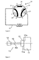
- the valve 20 has a first inlet 1 for connection to a liquid source (such as a pump), a second inlet 2 for introduction of a sample (typically using a syringe or a dedicated sample pump), a third inlet 3 and a first outlet 4 to/from a device for temporary storage of the fluid sample such as a retaining capillary loop 22 (well known within the art), and a second outlet 5 that connects the valve to the downstream part of the analytical or preparative system e.g. an ⁇ KTAexplorer system available from GE Healthcare.
- the valve has two waste outlets 6, 7 to allow a fluid to exit the valve directly to waste.
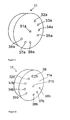
- the orifices of the inner stator face of the INV-907 are represented by circles in Fig. 1-3 , such as the circle 23 in the Fig. 2 .
- a groove 24 is provided in the inner stator face.
- the rotor is represented by its grooves 25, 26, 27.
- the grooves change positions with respect to the inner stator face, thus enabling new flow paths through the valve.
- the sample may be introduced either with a syringe or a dedicated sample pump.
- a conventional injection valve for example of the type shown, requires that the sample pump is connected to the port that alternatively should be used for the syringe, i.e. both alternatives could not be used at the same time.
- An object of the invention is to provide a sample injection valve that is more flexible for the user.
- sample injection valve which allows sample to be applied both by hand (for instance using a syringe) or automatically (such as by using a dedicated sample pump).
- the main parts of a typical rotary valve 10 are schematically shown in Fig. 4 (wherein no brackets or similar load carrying or fastening elements are shown).
- the rotary valve 10 has a stator 11, a rotor 12, a rotary shaft 13 that optionally may be provided with means (not shown) for recognizing its angular position and a driving unit 14 typically comprising a gear box and a motor (although a valve also may be operated manually).
- the rotor is rotatable with respect to the stator around a rotary axis RA of the valve.
- the stator 11 which is fixed with respect to the instrument into which it is built, is provided with ports (not shown in Fig. 4 ) for fluid communication with a fluid source and any components with which the valve is to co-operate.
- the ports may be positioned on any suitable position on the exterior surface of the stator.
- the ports are provided with means to connect capillaries or tubing. Such means may be of any suitable type, such as conventional Valco fittings well known to anyone skilled in the art.
- the ports are via channels in fluid communication with a corresponding set of orifices on an inner stator face 11a, i.e. that surface of the stator 11 that during operation is in contact with the rotor 12.
- the rotor 12 is typically formed as a disc and has an inner rotor face 12a that is pressed against the inner stator face 11a during operation.
- the inner rotor face 12a is provided with one or more grooves which interconnect different orifices of the inner stator face 11a depending on the rotary position of the rotor 12 with respect to the stator 11.
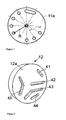
- Fig. 5 shows a simplified perspective view of the front side of a stator 11 according to one embodiment of the invention.
- the front side is here the side of the stator 11 opposite the inner stator face 11a.
- Inlet and outlet ports 31a-38a are illustrated.
- inlet/outlet ports in the stator are connected to orifices on the inner stator face 11a via bores (or any type of channels) it is possible to arrange the ports in a way that differs from the pattern of orifices on the inner stator face 11a by making non-linear channels between the ports and the orifices.
- the ports into the stator can even be positioned on another outer surface of the stator than the front side.
- the ports are shown as being positioned in-line with the inner stator face orifices as will be described below in relation to Figure 6 .
- stator 11 has eight ports 31a-38a that are used to connect the valve to all desired operative components of the instrument. According to other embodiments of the invention one or more additional orifices and ports can be provided to give some additional features to the valve.
- Port 31a is called a first inlet port 31a. It is positioned essentially in the middle of the stator and is used as inlet port from a main liquid source of the instrument, such as a pump, herein called the system pump.
- the system pump provides a flow of a single, so called buffer liquid or, alternatively, a fixed or variable mixture of two or more buffer liquids.
- Port 34a is called a first outlet port 34a and serves as the outlet port from which the liquid is allowed to exit to the remaining part of the instrument.
- a retaining loop such as a conventional capillary loop for use in a LCS, is in this embodiment connected at one end to a first connection port 32a and at the other end to a second connection port 35a.
- Two ports 36a, 37a, here called second and third inlet ports 36a, 37a are provided for introduction of a sample.
- the third inlet port 37a is intended for manual sample injection, typically using a syringe, while the second inlet port 36a is intended to be connected to a dedicated sample pump.
- the sample pump may be integrated in the instrument, or it may be a stand-alone device.
- the ports 33a and 38a are called second and third outlet ports 33a and 38a and are in this embodiment waste outlet ports.
- Fig. 6 is a perspective view of the stator 11 of Fig. 5 viewed from the other side, i.e. the inner stator face side 11a. Note that each port is connected to the inner stator face 11a via a channel ending in an orifice 32b-38b shown in the figure. For reason of simplicity, the orifice with number 32b is connected to the port with number 32a and so on.
- stator groove 39 is in this illustrated embodiment provided in the inner stator face 11a.
- the stator groove 39 is typically of the same width as an orifice diameter. It should be noted that although the stator groove 39 is preferred in order to allow the system pump to pump liquid through the system while the sample pump fills the loop (this will be described in detail below), it is not essential for the inventive idea. Without the stator groove 39 the system pump must either be at still when the sample pump fills the loop or there should be an additional waste outlet provided in the stator. For example another waste outlet may be provided between the second connection orifice 35b and the second inlet orifice 36b.
- Fig. 7 the general angular distribution of the orifices and the ends of the groove 39 for one embodiment of the invention is illustrated in Fig. 7 .
- the positions for orifices, groove ends (and not used positions) are here shown to be equally distributed around the center of the stator (which center coincides with the rotary axis of the valve).
- the positions of the orifices can be varied slightly without departing from the inventive idea. Since there are 12 such positions on the stator according to this embodiment, the partition angle ⁇ is 30° in this embodiment. All these positions are placed with essentially the same radial distance R to the rotational axis of the valve.
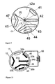
- the inner rotor face 12a of the rotor 12 of a valve embodiment according to the present invention is shown in Fig. 8 . It is provided with five grooves, called the first, second, third, fourth and fifth groove 41-45. The mutual positions and shapes of the grooves are more clearly illustrated in Fig. 9 .
- Each groove has both its ends ending at essentially the same radial distance R from the center, except for one end of groove 42 that ends in the center of the inner rotor face 12a (coinciding with the rotary axis of the valve).
- the radial distance R for the rotor is the same as the corresponding radial distance R of the stator.
- the first groove 41 extends over an angle ⁇ , which in the present embodiment is 30°.
- the second groove 42 is a straight groove from the center of the inner rotor face 12a out towards the rim, with a length of R, and is parted from the nearest end of the first groove 41 by the angle ⁇ .
- the third groove 43 begins at a position parted by the angle ⁇ from second groove 42, and ends at a position that is separated from the start position by an angle of 3 ⁇ . It is bent inwards toward the centre to form a knee 48 (or alternatively in an arcuate shape).
- the fourth groove 44 which occupies angle ⁇ , is equidistantly placed between the ends of groove 43.
- the fifth groove 45 has a shape similar to that of the third groove 43 (with a knee 47 displaced inwardly towards the center) but the end points are parted by an angle of 2 ⁇ , and begins at an angle ⁇ from the closest end of the third groove 43.
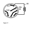
- the inner rotor face 12a When assembled, the inner rotor face 12a is pressed against the inner stator face 11a in a manner that is typical for any conventional rotary valve (which is well known for anyone skilled in the art, and will not be explained herein). Depending on the mutual angular positions of the rotor 12 and the stator 11 different operation modes are obtained for the valve. These are illustrated in Fig. 10-13 , wherein the grooves of the rotor are indicated by thick lines.
- valve In the first rotor position, as shown in Fig. 10 , the valve allows two separate flow paths.
- Fluid entering the first inlet orifice 31b typically from a pump, such as a system pump of a LCS, and of course through the first inlet port 31a, is allowed to pass through the valve via the second groove 42 and out of the first outlet orifice 34b and further out through the first outlet port 34a.
- the first outlet port 34a is intended to be connected to the main operative components of the instrument such as a chromatography column and monitoring devices such as UV monitors.
- Figures 10-13 grooves and orifices are shown and referred to and it is understood that each of said orifice mentioned is connected to a corresponding port as described above.
- a capillary loop 50 (or any device with a corresponding function) by introducing it through the third inlet port 37a. This is typically done with a syringe.
- the sample After entering the third inlet port 37a and further through the third inlet orifice 37b, the sample passes the third groove 43 to enter the loop 50 via the second connection orifice and port 35b and 35a.
- the loop 50 is connected to the second connection port 35a and at its other end to the first connection port 32a.
- fluid in the loop is allowed to exit to waste via the first groove 41 and the second outlet orifice and port 33b and 33a.
- the other orifices, ports and grooves of the valve are not active in the first rotor position.
- the second rotor position as shown in Fig.11 , is obtained by rotating the rotor an angle of 2 ⁇ counterclockwise (as seen from the view of Fig. 10 ) with respect to the first rotor position and allows two separate flow paths.
- the fluid that enters through the first inlet port orifice 31a, 31b will now pass through the valve via the second groove 42 and into the loop 50 via the first connection orifice and port 32b,a.
- the content of the loop will be forced into the main operative components of the instrument via the second connection port and orifice 35a, 35b, the fourth groove 44 and the first outlet orifice and port 34b,a.
- the sample is expelled using an opposite flow direction through the loop 50 with respect to how it was loaded, thus allowing it to travel the shortest possible way which is beneficial since it reduces the sample dilution to a minimum.
- a flow from a dedicated sample pump connected to the second inlet port 36a may be pumped to waste via the fifth groove 45 and the third outlet orifice and port 38b and 38a. This is useful for rinsing the tubing of the sample pump, as well as for rinsing the fifth groove 45.
- the other ports and grooves of the valve are not active in the second rotor position.
- the third rotor position is obtained by rotating the rotor an angle of 4 ⁇ counterclockwise (as seen from the view of Fig.10 ) with respect to the first rotor position.
- the third rotor position allows two separate flow paths through the valve.
- the fluid that enters through the first inlet port and orifice 31a and 31b will pass through the valve via the second rotor groove 42, the stator groove 39, the third rotor groove 43 and out of the valve via the first outlet orifice and port 34b and 34a into the main operative components of the instrument as described above.
- the capillary loop 50 it is possible to temporarily store a sample in the capillary loop 50 by introducing it through the second inlet port and orifice 36a and 36b. This is preferably done with a dedicated sample pump, as is well known in the art of liquid chromatography. After entering the second inlet orifice 36b the sample passes the fifth groove 45 to enter the loop 50 via the second connection orifice and port 35b and 35a. At its other end the loop 50 is connected to the first connection port 32a to allow fluid in the loop to exit to waste via the first connection orifice 32b, the fourth groove 44 and the second outlet orifice and port 33b and 33a.
- the other ports, orifices and grooves of the valve are not active in the third rotor position.
- a fourth rotor position is useful, although not necessary for the inventive use of the valve.
- the fourth rotor position is obtained by rotating the rotor an angle ⁇ counterclockwise (as seen from the view of Fig. 10 ) with respect to the first rotor position.
- the fluid that enters through the first inlet port and orifice 31a and 31b will pass directly to the waste outlet via the second rotor groove 42 and the second outlet orifice and port 33b and 33a.
- This position may be used in a case when it is desired to run the main pump of the instrument without forcing any fluid through the main operative components of the instrument downstream of the valve.
Applications Claiming Priority (2)
| Application Number | Priority Date | Filing Date | Title |
|---|---|---|---|
| SE0700462 | 2007-02-22 | ||
| PCT/SE2008/000111 WO2008103098A1 (en) | 2007-02-22 | 2008-02-11 | Rotation valve for sample injection |
Publications (3)
| Publication Number | Publication Date |
|---|---|
| EP2113081A1 EP2113081A1 (en) | 2009-11-04 |
| EP2113081A4 EP2113081A4 (en) | 2010-08-25 |
| EP2113081B1 true EP2113081B1 (en) | 2015-11-04 |
Family
ID=39710298
Family Applications (1)
| Application Number | Title | Priority Date | Filing Date |
|---|---|---|---|
| EP08705271.8A Active EP2113081B1 (en) | 2007-02-22 | 2008-02-11 | Rotation valve for sample injection |
Country Status (8)
| Country | Link |
|---|---|
| US (1) | US8186382B2 (zh) |
| EP (1) | EP2113081B1 (zh) |
| JP (2) | JP5270582B2 (zh) |
| CN (1) | CN101617226B (zh) |
| AU (1) | AU2008217771B2 (zh) |
| CA (1) | CA2676171C (zh) |
| DE (1) | DE202008018594U1 (zh) |
| WO (1) | WO2008103098A1 (zh) |
Families Citing this family (28)
| Publication number | Priority date | Publication date | Assignee | Title |
|---|---|---|---|---|
| DE102008006266B4 (de) | 2008-01-25 | 2011-06-09 | Dionex Softron Gmbh | Probengeber für die Flüssigkeitschromatographie, insbesondere für die Hochleistungsflüssigkeitschromatographie |
| US20120096932A1 (en) * | 2008-10-12 | 2012-04-26 | Anderson Jr James | Automated Sample Injection Apparatus, Multiport Valve, and Methods of Making and Using the Same |
| EP2344790B1 (en) * | 2008-11-13 | 2014-09-10 | GE Healthcare Bio-Sciences AB | Random access rotary valve |
| CN102460145B (zh) * | 2009-06-03 | 2015-04-29 | 安捷伦科技有限公司 | 使中间阀状态的压力差平衡的计量装置的样品注射器 |
| CN102612648B (zh) * | 2010-06-25 | 2015-04-08 | 高丽大学校产学协力团 | 多功能可选阀、包括该阀的多功能全自动液相色谱系统和用该系统分析样本的方法 |
| JP5646902B2 (ja) * | 2010-07-26 | 2014-12-24 | アークレイ株式会社 | 液体クロマトグラフィ装置およびインジェクションバルブ |
| JP5639914B2 (ja) * | 2011-02-02 | 2014-12-10 | ジーエルサイエンス株式会社 | 切換バルブ |
| US9304518B2 (en) | 2011-08-24 | 2016-04-05 | Bio-Rad Laboratories, Inc. | Modular automated chromatography system |
| US8960231B2 (en) * | 2011-09-21 | 2015-02-24 | Neil Robert Picha | Multi-mode injection valve |
| US9182886B2 (en) | 2011-11-14 | 2015-11-10 | Bio-Rad Laboratories Inc. | Chromatography configuration interface |
| US9546646B2 (en) * | 2013-01-16 | 2017-01-17 | Valco Instruments Company, L.P. | Pump and injector for liquid chromatography |
| US9841406B2 (en) | 2013-04-22 | 2017-12-12 | Sekisui Medical Co., Ltd. | Switching valve for flow type analysis apparatus |
| US9739383B2 (en) * | 2014-07-29 | 2017-08-22 | Idex Health & Science Llc | Multi-path selector valve |
| CN104482249B (zh) * | 2014-11-19 | 2017-01-11 | 苏州福润机械有限公司 | 一种基于大管径接口的轻质真空转阀 |
| CN104500784B (zh) * | 2015-01-14 | 2017-02-01 | 上海浦东汉威阀门有限公司 | 24通旋转阀 |
| CN104676047B (zh) * | 2015-02-16 | 2017-01-11 | 苏州赛谱仪器有限公司 | 进样阀 |
| GB201505421D0 (en) * | 2015-03-30 | 2015-05-13 | Ge Healthcare Bio Sciences Ab | A rotary valve and a chromatography system |
| DE202016100451U1 (de) | 2015-06-25 | 2016-02-16 | Dionex Softron Gmbh | Probengeber für die Flüssigkeitschromatographie, insbesondere für die Hochleistungsflüssigkeitschromatographie |
| CN205064928U (zh) * | 2015-09-25 | 2016-03-02 | 厦门建霖工业有限公司 | 中央净水器控制阀 |
| CN105927758B (zh) * | 2016-06-17 | 2018-04-13 | 厦门百霖净水科技有限公司 | 软水机控制阀及其操控方法 |
| DE102016121516B4 (de) * | 2016-11-10 | 2019-03-28 | Dionex Softron Gmbh | Verfahren und Vorrichtung zur Probenbeschickung |
| US10527192B2 (en) | 2018-02-15 | 2020-01-07 | Talis Biomedical Corporation | Rotary valve |
| US11680955B2 (en) * | 2018-04-04 | 2023-06-20 | Total Synthesis Ltd. | Fluid diverting module |
| US10820847B1 (en) | 2019-08-15 | 2020-11-03 | Talis Biomedical Corporation | Diagnostic system |
| CN110927299A (zh) * | 2019-11-26 | 2020-03-27 | 北京华创精科生物技术有限公司 | 一种进样阀 |
| CN110864138B (zh) * | 2019-11-26 | 2021-10-26 | 北京华创精科生物技术有限公司 | 一种切换阀 |
| CN114518426B (zh) * | 2022-03-03 | 2023-11-03 | 宁波艾纯生物科技有限公司 | 一种进样阀 |
| CN116575542B (zh) * | 2023-07-13 | 2023-10-03 | 杭州老板电器股份有限公司 | 分配组件及集成水槽 |
Family Cites Families (15)
| Publication number | Priority date | Publication date | Assignee | Title |
|---|---|---|---|---|
| GB1189995A (en) * | 1966-08-09 | 1970-04-29 | Bp Chem Int Ltd | Gas Chromatography Apparatus |
| US3868970A (en) * | 1973-06-04 | 1975-03-04 | Phillips Petroleum Co | Multipositional selector valve |
| US4068528A (en) * | 1976-01-19 | 1978-01-17 | Rheodyne Incorporated | Two position rotary valve for injecting sample liquids into an analysis system |
| US4158630A (en) | 1978-02-24 | 1979-06-19 | Stearns Stanley D | Chromatographic multi-sample valving apparatus |
| JPS58134286A (ja) * | 1982-02-04 | 1983-08-10 | Toray Ind Inc | 回転弁 |
| SE441118B (sv) * | 1982-04-07 | 1985-09-09 | Scanpump Ab | Strypdon |
| JPS61134668A (ja) * | 1984-12-06 | 1986-06-21 | Toyo Soda Mfg Co Ltd | 液注入装置 |
| US4625569A (en) * | 1984-01-17 | 1986-12-02 | Toyo Soda Manufacturing Co., Ltd. | Liquid injection device |
| US5010921A (en) * | 1989-07-17 | 1991-04-30 | Spectra-Physics, Inc. | Nonsymmetrical valve |
| US5623965A (en) * | 1995-10-30 | 1997-04-29 | Delco Electronics Corporation | Low effort vacuum valve assembly with rotary actuator |
| JPH09243624A (ja) * | 1996-03-05 | 1997-09-19 | Shimadzu Corp | 試料導入装置 |
| US6155123A (en) * | 1998-04-17 | 2000-12-05 | Rheodyne, L.P. | Multivalving sample injection system |
| US6012488A (en) * | 1998-09-17 | 2000-01-11 | Rheodyne, L.P. | Segmenting valve |
| US6672336B2 (en) * | 2001-11-28 | 2004-01-06 | Rheodyne, Lp | Dual random access, three-way rotary valve apparatus |
| CN1536359A (zh) * | 2003-04-10 | 2004-10-13 | 中国科学院大连化学物理研究所 | 一种气相色谱高温高压样品直接进样方法和装置 |
-
2008
- 2008-02-11 JP JP2009550835A patent/JP5270582B2/ja active Active
- 2008-02-11 CA CA2676171A patent/CA2676171C/en active Active
- 2008-02-11 US US12/523,356 patent/US8186382B2/en active Active
- 2008-02-11 DE DE202008018594.7U patent/DE202008018594U1/de not_active Expired - Lifetime
- 2008-02-11 AU AU2008217771A patent/AU2008217771B2/en not_active Ceased
- 2008-02-11 WO PCT/SE2008/000111 patent/WO2008103098A1/en active Application Filing
- 2008-02-11 EP EP08705271.8A patent/EP2113081B1/en active Active
- 2008-02-11 CN CN2008800055806A patent/CN101617226B/zh active Active
-
2013
- 2013-05-09 JP JP2013098993A patent/JP2013178268A/ja active Pending
Also Published As
| Publication number | Publication date |
|---|---|
| EP2113081A4 (en) | 2010-08-25 |
| EP2113081A1 (en) | 2009-11-04 |
| JP2013178268A (ja) | 2013-09-09 |
| AU2008217771B2 (en) | 2013-09-26 |
| DE202008018594U1 (de) | 2016-03-29 |
| CN101617226A (zh) | 2009-12-30 |
| CA2676171C (en) | 2015-10-20 |
| JP2010519535A (ja) | 2010-06-03 |
| AU2008217771A1 (en) | 2008-08-28 |
| CA2676171A1 (en) | 2008-08-24 |
| US20100032604A1 (en) | 2010-02-11 |
| WO2008103098A1 (en) | 2008-08-28 |
| US8186382B2 (en) | 2012-05-29 |
| CN101617226B (zh) | 2012-07-04 |
| JP5270582B2 (ja) | 2013-08-21 |
Similar Documents
| Publication | Publication Date | Title |
|---|---|---|
| EP2113081B1 (en) | Rotation valve for sample injection | |
| US8186381B2 (en) | Selection valve | |
| US8286663B2 (en) | Random access rotary valve | |
| US10047869B2 (en) | Versatile rotary valve | |
| EP2344790B1 (en) | Random access rotary valve | |
| US8225817B2 (en) | Flow distributing valve | |
| US8960231B2 (en) | Multi-mode injection valve | |
| US10746708B2 (en) | Rotary valve and a chromatography system |
Legal Events
| Date | Code | Title | Description |
|---|---|---|---|
| PUAI | Public reference made under article 153(3) epc to a published international application that has entered the european phase |
Free format text: ORIGINAL CODE: 0009012 |
|
| 17P | Request for examination filed |
Effective date: 20090826 |
|
| AK | Designated contracting states |
Kind code of ref document: A1 Designated state(s): AT BE BG CH CY CZ DE DK EE ES FI FR GB GR HR HU IE IS IT LI LT LU LV MC MT NL NO PL PT RO SE SI SK TR |
|
| DAX | Request for extension of the european patent (deleted) | ||
| A4 | Supplementary search report drawn up and despatched |
Effective date: 20100726 |
|
| 17Q | First examination report despatched |
Effective date: 20100809 |
|
| GRAP | Despatch of communication of intention to grant a patent |
Free format text: ORIGINAL CODE: EPIDOSNIGR1 |
|
| INTG | Intention to grant announced |
Effective date: 20150731 |
|
| GRAS | Grant fee paid |
Free format text: ORIGINAL CODE: EPIDOSNIGR3 |
|
| GRAA | (expected) grant |
Free format text: ORIGINAL CODE: 0009210 |
|
| AK | Designated contracting states |
Kind code of ref document: B1 Designated state(s): AT BE BG CH CY CZ DE DK EE ES FI FR GB GR HR HU IE IS IT LI LT LU LV MC MT NL NO PL PT RO SE SI SK TR |
|
| REG | Reference to a national code |
Ref country code: GB Ref legal event code: FG4D |
|
| REG | Reference to a national code |
Ref country code: CH Ref legal event code: EP |
|
| REG | Reference to a national code |
Ref country code: AT Ref legal event code: REF Ref document number: 759554 Country of ref document: AT Kind code of ref document: T Effective date: 20151115 |
|
| REG | Reference to a national code |
Ref country code: IE Ref legal event code: FG4D |
|
| REG | Reference to a national code |
Ref country code: DE Ref legal event code: R096 Ref document number: 602008040971 Country of ref document: DE |
|
| REG | Reference to a national code |
Ref country code: NL Ref legal event code: MP Effective date: 20151104 |
|
| REG | Reference to a national code |
Ref country code: LT Ref legal event code: MG4D |
|
| REG | Reference to a national code |
Ref country code: AT Ref legal event code: MK05 Ref document number: 759554 Country of ref document: AT Kind code of ref document: T Effective date: 20151104 |
|
| PG25 | Lapsed in a contracting state [announced via postgrant information from national office to epo] |
Ref country code: NL Free format text: LAPSE BECAUSE OF FAILURE TO SUBMIT A TRANSLATION OF THE DESCRIPTION OR TO PAY THE FEE WITHIN THE PRESCRIBED TIME-LIMIT Effective date: 20151104 Ref country code: ES Free format text: LAPSE BECAUSE OF FAILURE TO SUBMIT A TRANSLATION OF THE DESCRIPTION OR TO PAY THE FEE WITHIN THE PRESCRIBED TIME-LIMIT Effective date: 20151104 Ref country code: NO Free format text: LAPSE BECAUSE OF FAILURE TO SUBMIT A TRANSLATION OF THE DESCRIPTION OR TO PAY THE FEE WITHIN THE PRESCRIBED TIME-LIMIT Effective date: 20160204 Ref country code: HR Free format text: LAPSE BECAUSE OF FAILURE TO SUBMIT A TRANSLATION OF THE DESCRIPTION OR TO PAY THE FEE WITHIN THE PRESCRIBED TIME-LIMIT Effective date: 20151104 Ref country code: LT Free format text: LAPSE BECAUSE OF FAILURE TO SUBMIT A TRANSLATION OF THE DESCRIPTION OR TO PAY THE FEE WITHIN THE PRESCRIBED TIME-LIMIT Effective date: 20151104 Ref country code: IT Free format text: LAPSE BECAUSE OF FAILURE TO SUBMIT A TRANSLATION OF THE DESCRIPTION OR TO PAY THE FEE WITHIN THE PRESCRIBED TIME-LIMIT Effective date: 20151104 Ref country code: IS Free format text: LAPSE BECAUSE OF FAILURE TO SUBMIT A TRANSLATION OF THE DESCRIPTION OR TO PAY THE FEE WITHIN THE PRESCRIBED TIME-LIMIT Effective date: 20160304 |
|
| PG25 | Lapsed in a contracting state [announced via postgrant information from national office to epo] |
Ref country code: LV Free format text: LAPSE BECAUSE OF FAILURE TO SUBMIT A TRANSLATION OF THE DESCRIPTION OR TO PAY THE FEE WITHIN THE PRESCRIBED TIME-LIMIT Effective date: 20151104 Ref country code: SE Free format text: LAPSE BECAUSE OF FAILURE TO SUBMIT A TRANSLATION OF THE DESCRIPTION OR TO PAY THE FEE WITHIN THE PRESCRIBED TIME-LIMIT Effective date: 20151104 Ref country code: FI Free format text: LAPSE BECAUSE OF FAILURE TO SUBMIT A TRANSLATION OF THE DESCRIPTION OR TO PAY THE FEE WITHIN THE PRESCRIBED TIME-LIMIT Effective date: 20151104 Ref country code: AT Free format text: LAPSE BECAUSE OF FAILURE TO SUBMIT A TRANSLATION OF THE DESCRIPTION OR TO PAY THE FEE WITHIN THE PRESCRIBED TIME-LIMIT Effective date: 20151104 Ref country code: BE Free format text: LAPSE BECAUSE OF NON-PAYMENT OF DUE FEES Effective date: 20160229 Ref country code: GR Free format text: LAPSE BECAUSE OF FAILURE TO SUBMIT A TRANSLATION OF THE DESCRIPTION OR TO PAY THE FEE WITHIN THE PRESCRIBED TIME-LIMIT Effective date: 20160205 Ref country code: PL Free format text: LAPSE BECAUSE OF FAILURE TO SUBMIT A TRANSLATION OF THE DESCRIPTION OR TO PAY THE FEE WITHIN THE PRESCRIBED TIME-LIMIT Effective date: 20151104 Ref country code: PT Free format text: LAPSE BECAUSE OF FAILURE TO SUBMIT A TRANSLATION OF THE DESCRIPTION OR TO PAY THE FEE WITHIN THE PRESCRIBED TIME-LIMIT Effective date: 20160304 |
|
| PG25 | Lapsed in a contracting state [announced via postgrant information from national office to epo] |
Ref country code: CZ Free format text: LAPSE BECAUSE OF FAILURE TO SUBMIT A TRANSLATION OF THE DESCRIPTION OR TO PAY THE FEE WITHIN THE PRESCRIBED TIME-LIMIT Effective date: 20151104 |
|
| REG | Reference to a national code |
Ref country code: DE Ref legal event code: R097 Ref document number: 602008040971 Country of ref document: DE |
|
| PG25 | Lapsed in a contracting state [announced via postgrant information from national office to epo] |
Ref country code: EE Free format text: LAPSE BECAUSE OF FAILURE TO SUBMIT A TRANSLATION OF THE DESCRIPTION OR TO PAY THE FEE WITHIN THE PRESCRIBED TIME-LIMIT Effective date: 20151104 Ref country code: SK Free format text: LAPSE BECAUSE OF FAILURE TO SUBMIT A TRANSLATION OF THE DESCRIPTION OR TO PAY THE FEE WITHIN THE PRESCRIBED TIME-LIMIT Effective date: 20151104 Ref country code: DK Free format text: LAPSE BECAUSE OF FAILURE TO SUBMIT A TRANSLATION OF THE DESCRIPTION OR TO PAY THE FEE WITHIN THE PRESCRIBED TIME-LIMIT Effective date: 20151104 Ref country code: RO Free format text: LAPSE BECAUSE OF FAILURE TO SUBMIT A TRANSLATION OF THE DESCRIPTION OR TO PAY THE FEE WITHIN THE PRESCRIBED TIME-LIMIT Effective date: 20151104 |
|
| PLBE | No opposition filed within time limit |
Free format text: ORIGINAL CODE: 0009261 |
|
| STAA | Information on the status of an ep patent application or granted ep patent |
Free format text: STATUS: NO OPPOSITION FILED WITHIN TIME LIMIT |
|
| PG25 | Lapsed in a contracting state [announced via postgrant information from national office to epo] |
Ref country code: LU Free format text: LAPSE BECAUSE OF FAILURE TO SUBMIT A TRANSLATION OF THE DESCRIPTION OR TO PAY THE FEE WITHIN THE PRESCRIBED TIME-LIMIT Effective date: 20160211 Ref country code: MC Free format text: LAPSE BECAUSE OF FAILURE TO SUBMIT A TRANSLATION OF THE DESCRIPTION OR TO PAY THE FEE WITHIN THE PRESCRIBED TIME-LIMIT Effective date: 20151104 |
|
| REG | Reference to a national code |
Ref country code: CH Ref legal event code: PL |
|
| 26N | No opposition filed |
Effective date: 20160805 |
|
| PG25 | Lapsed in a contracting state [announced via postgrant information from national office to epo] |
Ref country code: LI Free format text: LAPSE BECAUSE OF NON-PAYMENT OF DUE FEES Effective date: 20160229 Ref country code: CH Free format text: LAPSE BECAUSE OF NON-PAYMENT OF DUE FEES Effective date: 20160229 |
|
| REG | Reference to a national code |
Ref country code: FR Ref legal event code: ST Effective date: 20161028 |
|
| PG25 | Lapsed in a contracting state [announced via postgrant information from national office to epo] |
Ref country code: SI Free format text: LAPSE BECAUSE OF FAILURE TO SUBMIT A TRANSLATION OF THE DESCRIPTION OR TO PAY THE FEE WITHIN THE PRESCRIBED TIME-LIMIT Effective date: 20151104 |
|
| REG | Reference to a national code |
Ref country code: IE Ref legal event code: MM4A |
|
| PG25 | Lapsed in a contracting state [announced via postgrant information from national office to epo] |
Ref country code: BE Free format text: LAPSE BECAUSE OF FAILURE TO SUBMIT A TRANSLATION OF THE DESCRIPTION OR TO PAY THE FEE WITHIN THE PRESCRIBED TIME-LIMIT Effective date: 20151104 |
|
| PG25 | Lapsed in a contracting state [announced via postgrant information from national office to epo] |
Ref country code: IE Free format text: LAPSE BECAUSE OF NON-PAYMENT OF DUE FEES Effective date: 20160211 Ref country code: FR Free format text: LAPSE BECAUSE OF NON-PAYMENT OF DUE FEES Effective date: 20160229 |
|
| PG25 | Lapsed in a contracting state [announced via postgrant information from national office to epo] |
Ref country code: MT Free format text: LAPSE BECAUSE OF FAILURE TO SUBMIT A TRANSLATION OF THE DESCRIPTION OR TO PAY THE FEE WITHIN THE PRESCRIBED TIME-LIMIT Effective date: 20151104 |
|
| PG25 | Lapsed in a contracting state [announced via postgrant information from national office to epo] |
Ref country code: HU Free format text: LAPSE BECAUSE OF FAILURE TO SUBMIT A TRANSLATION OF THE DESCRIPTION OR TO PAY THE FEE WITHIN THE PRESCRIBED TIME-LIMIT; INVALID AB INITIO Effective date: 20080211 Ref country code: CY Free format text: LAPSE BECAUSE OF FAILURE TO SUBMIT A TRANSLATION OF THE DESCRIPTION OR TO PAY THE FEE WITHIN THE PRESCRIBED TIME-LIMIT Effective date: 20151104 |
|
| PG25 | Lapsed in a contracting state [announced via postgrant information from national office to epo] |
Ref country code: TR Free format text: LAPSE BECAUSE OF FAILURE TO SUBMIT A TRANSLATION OF THE DESCRIPTION OR TO PAY THE FEE WITHIN THE PRESCRIBED TIME-LIMIT Effective date: 20151104 Ref country code: MT Free format text: LAPSE BECAUSE OF FAILURE TO SUBMIT A TRANSLATION OF THE DESCRIPTION OR TO PAY THE FEE WITHIN THE PRESCRIBED TIME-LIMIT Effective date: 20160229 |
|
| PG25 | Lapsed in a contracting state [announced via postgrant information from national office to epo] |
Ref country code: BG Free format text: LAPSE BECAUSE OF FAILURE TO SUBMIT A TRANSLATION OF THE DESCRIPTION OR TO PAY THE FEE WITHIN THE PRESCRIBED TIME-LIMIT Effective date: 20151104 |
|
| REG | Reference to a national code |
Ref country code: DE Ref legal event code: R081 Ref document number: 602008040971 Country of ref document: DE Owner name: CYTIVA SWEDEN AB, SE Free format text: FORMER OWNER: GE HEALTHCARE BIO-SCIENCES AB, UPPSALA, SE |
|
| PGFP | Annual fee paid to national office [announced via postgrant information from national office to epo] |
Ref country code: DE Payment date: 20221220 Year of fee payment: 16 |
|
| P01 | Opt-out of the competence of the unified patent court (upc) registered |
Effective date: 20230526 |
|
| PGFP | Annual fee paid to national office [announced via postgrant information from national office to epo] |
Ref country code: GB Payment date: 20231221 Year of fee payment: 17 |