EP2112816B1 - Procédé de tatouage numérique à infrarouges - Google Patents
Procédé de tatouage numérique à infrarouges Download PDFInfo
- Publication number
- EP2112816B1 EP2112816B1 EP09153475.0A EP09153475A EP2112816B1 EP 2112816 B1 EP2112816 B1 EP 2112816B1 EP 09153475 A EP09153475 A EP 09153475A EP 2112816 B1 EP2112816 B1 EP 2112816B1
- Authority
- EP
- European Patent Office
- Prior art keywords
- gamut
- infrared absorption
- low
- infrared
- strategy
- Prior art date
- Legal status (The legal status is an assumption and is not a legal conclusion. Google has not performed a legal analysis and makes no representation as to the accuracy of the status listed.)
- Expired - Fee Related
Links
Images


Classifications
-
- H—ELECTRICITY
- H04—ELECTRIC COMMUNICATION TECHNIQUE
- H04N—PICTORIAL COMMUNICATION, e.g. TELEVISION
- H04N1/00—Scanning, transmission or reproduction of documents or the like, e.g. facsimile transmission; Details thereof
- H04N1/32—Circuits or arrangements for control or supervision between transmitter and receiver or between image input and image output device, e.g. between a still-image camera and its memory or between a still-image camera and a printer device
- H04N1/32101—Display, printing, storage or transmission of additional information, e.g. ID code, date and time or title
- H04N1/32144—Display, printing, storage or transmission of additional information, e.g. ID code, date and time or title embedded in the image data, i.e. enclosed or integrated in the image, e.g. watermark, super-imposed logo or stamp
- H04N1/32149—Methods relating to embedding, encoding, decoding, detection or retrieval operations
- H04N1/32309—Methods relating to embedding, encoding, decoding, detection or retrieval operations in colour image data
Definitions
- This disclosure relates to a method and system for embedding information onto a substrate. More particularly, this disclosure is related towards a method and system for infrared watermarking using modified Gray Component Replacement/Under Color Removal (GCR/UCR) schemes and thus will be described with particular reference thereto. However, it should be appreciated that some embodiments are amenable to other applications.
- GCR/UCR Gray Component Replacement/Under Color Removal
- watermarking is a common way to enable security and other features in document production.
- This technique permits the insertion of information in the form of digital image signals into documents.
- This information may include copyright notices, security codes, identification data, bar codes, etc.
- This information may be hidden in images and exposed through various methods.
- This data may also be grouped in bits describing the information pertaining to a signal which can be read by a signal reader.
- Most common watermarking methods for images work in spatial or frequency domains.
- This data It is desirable for this data to remain hidden under normal visible light for practical and aesthetic purposes. It is also desirable to provide an infrared reading method that is capable of exposing the hidden data once it employs rendering techniques.
- the traditional approach is to render the encoded data with special inks that are not visible under normal light but have strong distinguishing characteristics under certain types of spectral illumination. However, these special inks and materials are often difficult to incorporate into standard electro-photographic or other non-impact printing systems.
- the same visual color can be achieved with different amounts and combinations of respective available colorants.
- This can easily be understood when considering that the human visual system - to a good approximation - can be modeled by a three component system, whereas printing is commonly achieved in a four or more component printing system. This underdetermined situation offers additional degrees of freedom that can be otherwise utilized.
- a common terminology used in the context of representing a three component color system with a four or more component rendering system is "metameric rendering". Therefore, when reading in an input color, various amounts of different toner may be used in order to match the desired effect.
- a generalization can be performed to arbitrary input images since the infrared characteristic is dominated by carbon black toner presence.
- One technique includes creating an infrared mark employing different infrared transmission characteristics of four or more different printing colorants. This creates an infrared mark by printing a first colorant combination with high infrared reflectance in close proximity to a second colorant with the same visual response under visible light while having a different infrared reflectance.
- This method does contain some drawbacks inherent within the process.
- One drawback includes a limited color palette because it is difficult to produce many colors under visible light that have the desired response under infrared light and thus the general inability to use this approach for infrared encoding of natural scene and other images.
- US-A-2002/0067844 describes embedding media with a digital watermark component.
- the media includes a cyan color plane, a magenta color plane, a yellow color plane, and a black color plane.
- the digital watermark component is embedded in the cyan, magenta, and yellow color planes.
- the digital watermark component is inverted and is embedded in the black color plane.
- the embedded media is illuminated with infrared light, which emphasizes the black color plane.
- An input device captures a digital image of the illuminated media.
- the digital watermark component is detected from the emphasized black plane.
- a method for infrared watermarking using modified gray component replacement/under color removal schemes includes providing a substrate; using a first black strategy to obtain a low infrared absorption gamut color conversion strategy yielding a low infrared absorption transform; using a second black strategy to obtain a high infrared absorption gamut color conversion strategy yielding a high infrared absorption transform; creating a gamut correlation mechanism which creates new high and low infrared absorption transforms by combining both said original low infrared absorption gamut and said high infrared absorption gamut into limited substantially similar shaped new gamuts; and printing a watermark on said substrate incorporating said limited substantially similar shaped gamuts for infrared watermark printing.
- this disclosure relates to a method for infrared watermarking of photographic images by matched differential black strategies.
- This disclosure describes an extension to the existing infrared coding approach based on pre-selected color palettes by using a combination of different approaches incorporating a gamut correlation mechanism.
- This disclosure teaching mapping two strategies into a common gamut shape for printing arbitrary infrared watermarks.
- One embodiment employs a strategy creating two matching gamuts as the intersection of the two initial gamuts.
- a second strategy teaches blending the two gamuts in the exclusionary area, still creating a single shape for the two gamuts.
- These single shape gamuts are used in the standard color correction process to create the input color to output print colorant transformation, commonly to create Lab to CMYK data.
- FIG. 1 one embodiment of a resultant printout is shown.
- This embodiment depicts a printed document 101 as shown under visible light 103 appears to be a house.
- the document 105 as viewed by an infrared camera 107 shows an infrared message "Infrared Mark”.
- Figure 1 depicts but one embodiment according to the present disclosure.
- document 101 as shown under visible light 103, may include any variety of images. In one embodiment, the image is in vivid color displaying no artifacts.
- Document 105 which is the same as Document 101 is shown under infrared light displays an arbitrary message.
- infrared light we will consider the term "infrared light” to always refer to the ability to detect a infrared signal using the appropriate combination of infrared illuminate and infrared detectors, such as cameras, scanners and the like.
- the arbitrary infrared message may include information that can be read by any variety of readers.
- the infrared markings display a bar code which may be scanned in order to list the price of an item.
- Document 105 displays a security symbol ensuring that the document originates from a certain source. It should be noted that Document 101 and 105 display different images although they are the same document. The difference in light source exposes the amount of infrared absorption capabilities of the ink.
- FIG. 2 shows different gamut extensions for a low K case 203 and high K case 205.
- the lower part of the gamut is influenced by a black strategy. Using different black strategies or different GCR/UCR schemes, different effective gamuts can be obtained.
- the gamut for the low K strategy is normally limited on the dark end to less dark colors.
- the low K gamut 203 has a higher minimum range. Therefore, it is difficult to reach lower colors C on this gamut 203 with the low K strategy.
- a gamut limiting method which maps the input image to the boundary of the low K gamut 203, where for the purpose of description we will equate the K (black) toner (ink, etc.) with the dominant infrared modifying material. Independent of whether the watermark dictates the color from the high K 205 or low K 203, black strategy.
- This gamut limitation also automatically corrects the gamut mapping of color C since both cases are now mapped using the identical target gamut 201. It should be noted that even if there is an influence in the cusp location, finding a minimal gamut will adjust those gamut target points.
- the input colors lead to a stronger and more consistent watermark signal. This does however limit the overall size of the gamut to, generally, the low K 203 strategy.
- FIG. 3 is a similar gamut to the one in Figure 2 .
- This gamut 301 employs a blending strategy where the original two gamuts are blended into a single shape 301.
- the low K gamut 203 switches to the high K gamut 205 at regions not available in the low K gamut 203 approach.
- gamut blending can fulfill this need. In the region close to the boundary 303 of the smaller gamut 203, gamut blending is performed that will result in a complete switch outside the smaller gamut 203. This switch is however done with a blending approach which will change the color C gradually as it approaches the lower bound. In this embodiment the overall color gamut is increased. Furthermore, a large number of dark colors is now mapped to two identical CMYK colorant mixtures, depending on the blending function. In either case (the intersection or blending) the two gamuts (low K and high K) are identical in their shape and size for all color conversions.
- printer characterization data (at step 401). These characterization data are generally created by printing pre-determined CMYK combinations and by measuring the resultant colors. The resultant colors may be measured in Lab, RBG, etc.
- the method continues with adopting a low K strategy (at step 403) and thereby by defining the extend to which CMYK combinations can create Lab colors under the restricted use of the K component.
- the low K strategy will result in a low K gamut.
- the gamut is generally used as printer space and imbedded inherently with the three component to four component transformation as will be seen later.
- the method continues with computing the boundary for the low K gamut (at step 405).
- the boundary for the low K gamut is used the subsequent steps of the method.
- the method then continues (at step 407) with adopting a high K strategy and resulting gamut.
- This is similar to the previous step of adopting a low K strategy except in this step the black component is significantly higher. This is mainly due to the black's relationship with infrared absorption.
- step 409 The method continues (at step 409) with computing the boundary for the high K gamut. Similar to step 405, a boundary is computed for the high K gamut.
- the method continues (at step 411) with choosing blending or clipping as a strategy for producing a combination resulting gamut.
- blending or clipping as a strategy for producing a combination resulting gamut.
- a resultant gamut that is produced via blending will employ a larger gamut 301 and produce a higher range of color.
- a gamut that is produced via clipping will create a more consistent watermark signal using a smaller gamut 201.
- the combination gamut is now chosen to serve as the gamut boundary for the inversion of the characterization (at step 413), id est, for inverting the CMYK to Lab transform into the needed Lab to CMYK transform using standard color management methods.
- the inversion table is populated by characterization data that both fulfill the infrared requirement (through their respective high and low K attributes) as well as the gamut boundary requirement.
- this essentially limits the characterization data that is to be used and in the blending scenario this essentially populates some of the entries with CMYK and Lab combinations that do not fulfill stringent infrared requirements.
- the method continues (at step 415) with storing the two resultant Lab to CMYK trasnforms as the high K and low K gamuts.
- the resultant high K and low K gamuts are the gamuts that are stored for processing the image, where for brevity we use "low K gamut" to indicate the Lab to CMYK inverse transform derived from the gamut boundary of the low K gamut.
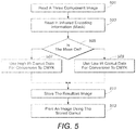
- the method begins with reading in a three component image (at step 501).
- the three component image is read into the printing device.
- the method continues with reading in infrared and coding information (at step 503).
- the image is generally the image as seen under natural light.
- the infrared encoding information or the mask may be seen under infrared light.
- the printing device can read in these two components which will constitute the strategy for printing.
- the method continues (at step 505) with determining, while printing, if the mask is on.
- the printer will use the high infrared gamut data for conversion to CMYK.
- the printer will use the low infrared gamut data for conversion to CMYK.
- the method continues (at step 509) with storing the resultant image.
- the image after implementation of this process will, under visual light, show the desired image and under infrared light show the encoded masked information.
- the image may then be printed (at step 511) using the stored gamuts.
Claims (8)
- Procédé de tatouage numérique aux infrarouges utilisant des schémas d'élimination des sous-couleurs/de remplacement de composante grise modifiée, comprenant les étapes suivantes :disposer d'un substrat ;utiliser une première stratégie noire (403, 405) pour obtenir une stratégie de conversion de gamme de couleurs à faible absorption des infrarouges, engendrant une transformée de faible absorption des infrarouges ;utiliser une deuxième stratégie noire (407, 409) pour obtenir une stratégie de conversion de gamme de couleurs à forte absorption des infrarouges, engendrant une transformée de forte absorption des infrarouges ;créer (411) un mécanisme de corrélation de gammes qui crée de nouvelles transformées de forte et faible absorption des infrarouges en combinant ensemble ladite gamme à faible absorption des infrarouges originale et ladite gamme à forte absorption des infrarouges originales en de nouvelles gammes de forme sensiblement similaire limitées ; etimprimer (523) un tatouage numérique sur ledit substrat incorporant lesdites gammes de forme sensiblement similaire limitées pour une impression de tatouage numérique aux infrarouges.
- Procédé selon la revendication 1, dans lequel ledit mécanisme de corrélation de gammes est un mélange de ladite gamme à faible absorption des infrarouges et de ladite gamme à forte absorption des infrarouges.
- Procédé selon la revendication 1, dans lequel ledit mécanisme de corrélation de gammes est une intersection de ladite gamme à faible absorption des infrarouges et de ladite gamme à forte absorption des infrarouges.
- Procédé selon l'une quelconque des revendications précédentes, dans lequel ladite stratégie de gamme à forte absorption des infrarouges comprend l'utilisation de quantités relativement élevées de toner noir comprenant des quantités importantes de carbone.
- Procédé selon l'une quelconque des revendications précédentes, dans lequel ladite stratégie de gamme à faible absorption des infrarouges comprend l'utilisation de quantités relativement réduites de toner noir comprenant des quantités importantes de carbone.
- Procédé selon l'une quelconque des revendications précédentes, dans lequel ladite gamme à forte absorption des infrarouges et ladite gamme à faible absorption des infrarouges sont identiques.
- Procédé selon l'une quelconque des revendications précédentes, dans lequel ladite gamme à forte absorption des infrarouges imprime en utilisant des quantités comparativement importantes de toner noir, et ladite gamme à faible absorption des infrarouges imprime en utilisant des quantités comparativement réduites de toner noir.
- Procédé selon l'une quelconque des revendications précédentes, dans lequel ledit tatouage numérique aux infrarouges crée une image arbitraire.
Applications Claiming Priority (1)
| Application Number | Priority Date | Filing Date | Title |
|---|---|---|---|
| US12/106,709 US8111432B2 (en) | 2008-04-21 | 2008-04-21 | Infrared watermarking of photographic images by matched differential black strategies |
Publications (3)
| Publication Number | Publication Date |
|---|---|
| EP2112816A2 EP2112816A2 (fr) | 2009-10-28 |
| EP2112816A3 EP2112816A3 (fr) | 2010-01-06 |
| EP2112816B1 true EP2112816B1 (fr) | 2017-08-23 |
Family
ID=40637248
Family Applications (1)
| Application Number | Title | Priority Date | Filing Date |
|---|---|---|---|
| EP09153475.0A Expired - Fee Related EP2112816B1 (fr) | 2008-04-21 | 2009-02-23 | Procédé de tatouage numérique à infrarouges |
Country Status (3)
| Country | Link |
|---|---|
| US (1) | US8111432B2 (fr) |
| EP (1) | EP2112816B1 (fr) |
| JP (1) | JP5000676B2 (fr) |
Families Citing this family (35)
| Publication number | Priority date | Publication date | Assignee | Title |
|---|---|---|---|---|
| US20110001314A1 (en) * | 2009-07-01 | 2011-01-06 | Xerox Corporation | Security codes within scratch-off layers and method of embedding thereof |
| US8342576B2 (en) | 2010-02-09 | 2013-01-01 | Xerox Corporation | Method and system of printing a scratch-off document |
| US8064102B1 (en) | 2010-07-01 | 2011-11-22 | Xerox Corporation | Embedding frequency modulation infrared watermark in digital document |
| JP5715385B2 (ja) * | 2010-11-19 | 2015-05-07 | キヤノン株式会社 | 情報生成装置、情報生成方法、画像処理装置、画像処理方法 |
| JP5715386B2 (ja) * | 2010-11-19 | 2015-05-07 | キヤノン株式会社 | 画像処理装置及びその制御方法、並びにプログラム及び記憶媒体 |
| US8928948B2 (en) * | 2010-12-01 | 2015-01-06 | Xerox Corporation | Method of creating non-patterned security elements |
| US8659799B2 (en) * | 2011-02-25 | 2014-02-25 | Xerox Corporation | IR specialty imaging methods and systems |
| US8797602B2 (en) * | 2011-03-23 | 2014-08-05 | Xerox Corporation | UV and IR specialty imaging methods and systems |
| US8587832B2 (en) * | 2011-06-10 | 2013-11-19 | Xerox Corporation | Dual color matching feedback control method and system for hiding infrared markings and other information |
| CZ2011451A3 (cs) * | 2011-07-25 | 2013-02-06 | Daveton Consulting Company, S.R.O. | Ochranný prvek k zabezpecení tiskovin, predevsím pro digitální tisk |
| JP6111677B2 (ja) * | 2012-03-23 | 2017-04-12 | 株式会社リコー | 情報処理装置、画像生成方法及び画像生成プログラム |
| US8699089B2 (en) | 2012-07-19 | 2014-04-15 | Xerox Corporation | Variable data image watermarking using infrared sequence structures in black separation |
| US8730527B2 (en) | 2012-09-27 | 2014-05-20 | Xerox Corporation | Embedding infrared marks in gloss security printing |
| US10051156B2 (en) | 2012-11-07 | 2018-08-14 | Xerox Corporation | System and method for producing correlation and gloss mark images |
| US8896886B2 (en) | 2013-02-26 | 2014-11-25 | Xerox Corporation | Color differential gloss security printing |
| US9106847B2 (en) | 2013-09-18 | 2015-08-11 | Xerox Corporation | System and method for producing color shifting or gloss effect and recording medium with color shifting or gloss effect |
| US9193201B2 (en) | 2013-09-18 | 2015-11-24 | Xerox Corporation | System and method for producing color shifting or gloss effect and recording medium with color shifting or gloss effect |
| US9083896B2 (en) | 2013-09-18 | 2015-07-14 | Xerox Corporation | System and method for producing color shifting or gloss effect and recording medium with color shifting or gloss effect |
| US9118870B2 (en) | 2013-09-18 | 2015-08-25 | Xerox Corporation | System and method for producing color shifting or gloss effect and recording medium with color shifting or gloss effect |
| US9088736B2 (en) | 2013-09-18 | 2015-07-21 | Xerox Corporation | System and method for producing color shifting or gloss effect and recording medium with color shifting or gloss effect |
| US9100592B2 (en) | 2013-09-18 | 2015-08-04 | Xerox Corporation | System and method for producing color shifting or gloss effect and recording medium with color shifting or gloss effect |
| US9319557B2 (en) | 2013-09-18 | 2016-04-19 | Xerox Corporation | System and method for producing color shifting or gloss effect and recording medium with color shifting or gloss effect |
| US9275428B2 (en) | 2014-03-20 | 2016-03-01 | Xerox Corporation | Dark to light watermark without special materials |
| US9082068B1 (en) | 2014-05-06 | 2015-07-14 | Xerox Corporation | Color shift printing without using special marking materials |
| US9756212B2 (en) | 2015-11-25 | 2017-09-05 | Xerox Corporation | System and method for producing seesaw gloss effect and recording medium with seesaw gloss effect |
| US9516190B1 (en) | 2015-11-25 | 2016-12-06 | Xerox Corporation | System and method for producing seesaw gloss effect and recording medium with seesaw gloss effect |
| US9674392B1 (en) | 2015-11-25 | 2017-06-06 | Xerox Corporation | System and method for producing seesaw gloss effect and recording medium with seesaw gloss effect |
| US9538041B1 (en) | 2015-11-25 | 2017-01-03 | Xerox Corporation | System and method for producing seesaw gloss effect and recording medium with seesaw gloss effect |
| US9674391B1 (en) | 2015-11-25 | 2017-06-06 | Xerox Corporation | System and method for producing seesaw gloss effect and recording medium with seesaw gloss effect |
| US9614995B1 (en) | 2016-05-02 | 2017-04-04 | Xerox Corporation | System and method for generating vector based correlation marks and vector based gloss effect image patterns for rendering on a recording medium |
| US9661186B1 (en) | 2016-06-02 | 2017-05-23 | Xerox Corporation | System and method for rendering gloss effect image patterns on a recording medium |
| US9781294B1 (en) | 2016-08-09 | 2017-10-03 | Xerox Corporation | System and method for rendering micro gloss effect image patterns on a recording medium |
| US10313556B1 (en) | 2018-01-16 | 2019-06-04 | Xerox Corporation | Method and system for production quality gloss marks |
| CN112130776A (zh) * | 2019-06-25 | 2020-12-25 | 株式会社理光 | 图像处理装置、打印系统、记录媒介及潜像嵌入方法 |
| US11677891B1 (en) | 2022-02-04 | 2023-06-13 | Xerox Corporation | Image path that supports device based infrared mark imaging |
Family Cites Families (11)
| Publication number | Priority date | Publication date | Assignee | Title |
|---|---|---|---|---|
| US6763123B2 (en) | 1995-05-08 | 2004-07-13 | Digimarc Corporation | Detection of out-of-phase low visibility watermarks |
| SE517445C2 (sv) * | 1999-10-01 | 2002-06-04 | Anoto Ab | Positionsbestämning på en yta försedd med ett positionskodningsmönster |
| US7738673B2 (en) * | 2000-04-19 | 2010-06-15 | Digimarc Corporation | Low visible digital watermarks |
| JP4335829B2 (ja) * | 2005-02-22 | 2009-09-30 | 株式会社日立製作所 | 印刷方法および印刷画像の検証方法 |
| US8980504B2 (en) | 2006-05-11 | 2015-03-17 | Xerox Corporation | Substrate fluorescence mask utilizing a multiple color overlay for embedding information in printed documents |
| US8283004B2 (en) * | 2006-05-11 | 2012-10-09 | Xerox Corporation | Substrate fluorescence pattern mask for embedding information in printed documents |
| US8277908B2 (en) | 2006-05-11 | 2012-10-02 | Xerox Corporation | Substrate fluorescence mask for embedding information in printed documents |
| US8821996B2 (en) | 2007-05-29 | 2014-09-02 | Xerox Corporation | Substrate fluorescent non-overlapping dot patterns for embedding information in printed documents |
| US8460781B2 (en) | 2007-06-05 | 2013-06-11 | Xerox Corporation | Infrared encoding of security elements using standard xerographic materials |
| US8455087B2 (en) | 2007-06-05 | 2013-06-04 | Xerox Corporation | Infrared encoding of security elements using standard xerographic materials with distraction patterns |
| JP4392522B2 (ja) * | 2008-10-07 | 2010-01-06 | 健治 吉田 | 複写装置 |
-
2008
- 2008-04-21 US US12/106,709 patent/US8111432B2/en not_active Expired - Fee Related
-
2009
- 2009-02-23 EP EP09153475.0A patent/EP2112816B1/fr not_active Expired - Fee Related
- 2009-03-23 JP JP2009070625A patent/JP5000676B2/ja not_active Expired - Fee Related
Non-Patent Citations (1)
| Title |
|---|
| None * |
Also Published As
| Publication number | Publication date |
|---|---|
| EP2112816A3 (fr) | 2010-01-06 |
| JP2009268081A (ja) | 2009-11-12 |
| US20090262400A1 (en) | 2009-10-22 |
| US8111432B2 (en) | 2012-02-07 |
| JP5000676B2 (ja) | 2012-08-15 |
| EP2112816A2 (fr) | 2009-10-28 |
Similar Documents
| Publication | Publication Date | Title |
|---|---|---|
| EP2112816B1 (fr) | Procédé de tatouage numérique à infrarouges | |
| US9148546B2 (en) | System and method for producing color shifting or gloss effect and recording medium with color shifting or gloss effect | |
| US9237253B2 (en) | System and method for producing color shifting or gloss effect and recording medium with color shifting or gloss effect | |
| US9781294B1 (en) | System and method for rendering micro gloss effect image patterns on a recording medium | |
| US9415606B2 (en) | System and method for producing color shifting or gloss effect and recording medium with color shifting or gloss effect | |
| JP5869756B2 (ja) | 条件等色描画による印刷された基板の磁気透かし | |
| US9614995B1 (en) | System and method for generating vector based correlation marks and vector based gloss effect image patterns for rendering on a recording medium | |
| US9118870B2 (en) | System and method for producing color shifting or gloss effect and recording medium with color shifting or gloss effect | |
| US9083896B2 (en) | System and method for producing color shifting or gloss effect and recording medium with color shifting or gloss effect | |
| US9088736B2 (en) | System and method for producing color shifting or gloss effect and recording medium with color shifting or gloss effect | |
| US9100592B2 (en) | System and method for producing color shifting or gloss effect and recording medium with color shifting or gloss effect | |
| US11102372B2 (en) | Information recording body, medium and printed product | |
| US9661186B1 (en) | System and method for rendering gloss effect image patterns on a recording medium | |
| US9883073B2 (en) | System and method for producing seesaw gloss effect and recording medium with seesaw gloss effect | |
| US9538041B1 (en) | System and method for producing seesaw gloss effect and recording medium with seesaw gloss effect | |
| US9674392B1 (en) | System and method for producing seesaw gloss effect and recording medium with seesaw gloss effect | |
| US9516190B1 (en) | System and method for producing seesaw gloss effect and recording medium with seesaw gloss effect | |
| US9674391B1 (en) | System and method for producing seesaw gloss effect and recording medium with seesaw gloss effect | |
| US11872833B2 (en) | Infrared effect preserved on copy | |
| JP2004159349A (ja) | 画像変換装置および方法、パターン読取装置および方法並びにプログラム |
Legal Events
| Date | Code | Title | Description |
|---|---|---|---|
| PUAI | Public reference made under article 153(3) epc to a published international application that has entered the european phase |
Free format text: ORIGINAL CODE: 0009012 |
|
| AK | Designated contracting states |
Kind code of ref document: A2 Designated state(s): AT BE BG CH CY CZ DE DK EE ES FI FR GB GR HR HU IE IS IT LI LT LU LV MC MK MT NL NO PL PT RO SE SI SK TR |
|
| AX | Request for extension of the european patent |
Extension state: AL BA RS |
|
| PUAL | Search report despatched |
Free format text: ORIGINAL CODE: 0009013 |
|
| AK | Designated contracting states |
Kind code of ref document: A3 Designated state(s): AT BE BG CH CY CZ DE DK EE ES FI FR GB GR HR HU IE IS IT LI LT LU LV MC MK MT NL NO PL PT RO SE SI SK TR |
|
| AX | Request for extension of the european patent |
Extension state: AL BA RS |
|
| RIC1 | Information provided on ipc code assigned before grant |
Ipc: H04N 1/32 20060101AFI20090527BHEP Ipc: G06T 1/00 20060101ALI20091202BHEP |
|
| 17P | Request for examination filed |
Effective date: 20100706 |
|
| AKX | Designation fees paid |
Designated state(s): DE FR GB |
|
| 17Q | First examination report despatched |
Effective date: 20100816 |
|
| GRAP | Despatch of communication of intention to grant a patent |
Free format text: ORIGINAL CODE: EPIDOSNIGR1 |
|
| INTG | Intention to grant announced |
Effective date: 20170322 |
|
| GRAS | Grant fee paid |
Free format text: ORIGINAL CODE: EPIDOSNIGR3 |
|
| GRAA | (expected) grant |
Free format text: ORIGINAL CODE: 0009210 |
|
| AK | Designated contracting states |
Kind code of ref document: B1 Designated state(s): DE FR GB |
|
| REG | Reference to a national code |
Ref country code: GB Ref legal event code: FG4D |
|
| REG | Reference to a national code |
Ref country code: DE Ref legal event code: R096 Ref document number: 602009047850 Country of ref document: DE |
|
| REG | Reference to a national code |
Ref country code: DE Ref legal event code: R097 Ref document number: 602009047850 Country of ref document: DE |
|
| PLBE | No opposition filed within time limit |
Free format text: ORIGINAL CODE: 0009261 |
|
| STAA | Information on the status of an ep patent application or granted ep patent |
Free format text: STATUS: NO OPPOSITION FILED WITHIN TIME LIMIT |
|
| 26N | No opposition filed |
Effective date: 20180524 |
|
| REG | Reference to a national code |
Ref country code: DE Ref legal event code: R119 Ref document number: 602009047850 Country of ref document: DE |
|
| GBPC | Gb: european patent ceased through non-payment of renewal fee |
Effective date: 20180223 |
|
| REG | Reference to a national code |
Ref country code: FR Ref legal event code: ST Effective date: 20181031 |
|
| PG25 | Lapsed in a contracting state [announced via postgrant information from national office to epo] |
Ref country code: DE Free format text: LAPSE BECAUSE OF NON-PAYMENT OF DUE FEES Effective date: 20180901 |
|
| PG25 | Lapsed in a contracting state [announced via postgrant information from national office to epo] |
Ref country code: GB Free format text: LAPSE BECAUSE OF NON-PAYMENT OF DUE FEES Effective date: 20180223 Ref country code: FR Free format text: LAPSE BECAUSE OF NON-PAYMENT OF DUE FEES Effective date: 20180228 |