EP2112732A1 - Chemin pour conducteurs électriques et dispositif de retenue pouvant être appliqué audit chemin - Google Patents
Chemin pour conducteurs électriques et dispositif de retenue pouvant être appliqué audit chemin Download PDFInfo
- Publication number
- EP2112732A1 EP2112732A1 EP09380080A EP09380080A EP2112732A1 EP 2112732 A1 EP2112732 A1 EP 2112732A1 EP 09380080 A EP09380080 A EP 09380080A EP 09380080 A EP09380080 A EP 09380080A EP 2112732 A1 EP2112732 A1 EP 2112732A1
- Authority
- EP
- European Patent Office
- Prior art keywords
- raceway
- electrical conductors
- wall
- marginal area
- retainer
- Prior art date
- Legal status (The legal status is an assumption and is not a legal conclusion. Google has not performed a legal analysis and makes no representation as to the accuracy of the status listed.)
- Withdrawn
Links
Images


Classifications
-
- H—ELECTRICITY
- H02—GENERATION; CONVERSION OR DISTRIBUTION OF ELECTRIC POWER
- H02G—INSTALLATION OF ELECTRIC CABLES OR LINES, OR OF COMBINED OPTICAL AND ELECTRIC CABLES OR LINES
- H02G3/00—Installations of electric cables or lines or protective tubing therefor in or on buildings, equivalent structures or vehicles
- H02G3/02—Details
- H02G3/04—Protective tubing or conduits, e.g. cable ladders or cable troughs
- H02G3/0406—Details thereof
-
- H—ELECTRICITY
- H02—GENERATION; CONVERSION OR DISTRIBUTION OF ELECTRIC POWER
- H02G—INSTALLATION OF ELECTRIC CABLES OR LINES, OR OF COMBINED OPTICAL AND ELECTRIC CABLES OR LINES
- H02G3/00—Installations of electric cables or lines or protective tubing therefor in or on buildings, equivalent structures or vehicles
- H02G3/02—Details
- H02G3/04—Protective tubing or conduits, e.g. cable ladders or cable troughs
- H02G3/0431—Wall trunking
Definitions
- This invention relates to a raceway for electrical conductors, in particular one of the type that is made by extruding synthetic plastics material and configured as a channel-shaped section made up of a bottom strip that is flanked orthogonally by two opposite, symmetrical walls, with respect to a middle plane perpendicular to the bottom strip, which form at the free end thereof a channel-shaped edge for fitting a cover section.
- the width of the bottom and the height of the walls can be variable, without said walls loosing their symmetry, so as to achieve a wide range of raceways.
- raceways of this type which the invention refers to, are organized so that they are provided with means to enable the firm attachment of, on the one hand, detachable cross members intended to retain the cables installed in the raceway and, on the other hand, the end of one raceway section with the end of another raceway section that is axially contiguous therewith.
- the invention also relates to an electrical conductor retainer applicable to the raceway according to the invention.
- documents ES2027981T3 , ES2223347T3 and ES2266321T3 are known, which refer to raceways having a slat in cantilever arrangement which, ending in a thickened free end and being arranged on the inner face of the marginal upper area of the free edge of the raceway walls, is intended to act as a support for elements retaining the conductors that are housed in the raceway, with said retainer elements being attached at their ends, like bridges, to said slats in cantilever arrangement.
- Document ES2027981T3 relates to a retainer consisting of a staple made up of a single part with no pre-cut sections for adapting the length of said staple by removing some of the portions and, which also has its two ends with different formal and functional characteristics, whereby one end behaves like a hinged clamp and the other one is simply applied against the edge of the raceway by the pushing action caused by the elasticity of the other end .
- the object of document ES2174563T3 is a retainer consisting of a staple that is not a single piece, and which is instead made up of the association of a bottom metal part and a top part made from synthetic material.
- Document ES2223347T3 relates to a retainer consisting of a clamp which, at one of its ends, has a foot like an elastic grab with a heel and a nail which enable it to adopt two stable clamp positions: one a waiting position and the other a position working as a retainer, while the other end of said clamp has a head provided with an attachment nail and an assembly wedge, so that by pressing, the head moves behind a closure section provided on the edge of the raceway and the nail is retained in a thickened part of said closure section.
- Document ES2266321T3 discloses a retainer in which the attachment staples are joined into pairs at their feet, and each pair of staples is joined to another identical pair, so that the staples can be separated, to perform their retainer function, into four independent staples, which allows to adapt the retainer to two possible lengths: one determined by a pair of aligned staples and one corresponding to a single loose staple.
- retainer staples are made up of a rigid part, substantially flat and elongated, which covers the width of a raceway between the top ends of the side walls of said raceway, said part having transverse swerving grooves that separate some modular parts joined together by side flaps stemming from the base of the part, and which are provided with grooves that weaken the thickness and can be broken.
- Said parts have on their opposite sides one or two mutually alternated lugs that are elastically inserted in tubular endings formed on the top edges of the raceway compartment partitions.
- the ends of the rigid part consist of a base, with reduced thickness for elastic flexibility, limited by a bead, side flaps and end pins with an outer stump that is inserted into openings formed in the endings of the raceway walls, by the elastic area being compressed and then expanding.
- the solution has been adopted to reshape, inside the raceway, the structure of the support means for said retainer elements by adopting a three-dimensional shape so as to obtain greater rigidity, and form the retainers so that they are made up of a single part that has its ends the same and which can be split maintaining the possibility of attaching it to the raceway and/or to the longitudinal compartment partitions that may be placed at the bottom of the raceway.
- the raceway that is the object of this invention has been developed, which consists of a raceway of the type cited at the beginning, characterized in that the top end of each of the opposite walls has a inclined marginal area, which is tilted upwards and towards the inside of the raceway, and on the top face of said inclined marginal area a seating flap is arranged that is parallel to the bottom strip and which forms, together with said inclined marginal area and the channel-shaped edge, a tubular section in cantilever arrangement from the free end of which there emerges a short anchoring wing perpendicular to said bottom strip.
- the retainer according to the invention for electrical cables has been developed, which is made up of a single oblong part that has a "U"-shaped straight section and which differentiates in a plurality of separable, longitudinal parts, with the two end parts being the same and being provided with the same attachment means suitable for attaching to the top ends of the opposite side walls of the raceway, whereas the inner parts have a different structure from said end parts and have attachment means suitable for attaching to the top seamed edges of detachable, longitudinal compartment partitions that may be provided in the raceway.
- the retainer according to the invention is characterized in that said attachment means on the end parts, suitable for attaching to the top ends of the opposite side walls of the raceway, are made up of an elastic clamp arrangement that has two flat, coplanar flanges, which are separated and in cantilever arrangement, and an elastic hooked finger facing the separation space between said flat flanges.
- the inclined marginal area on the top end of the opposite walls establishes a space for locating the channel-shaped edge
- said channel-shaped edge is made up of a straight portion followed by an arched portion that opens towards said inclined marginal area and projects over it without projecting out of it, with said straight portion emerging from said inclined marginal area and extending to the seating flap, which emerges orthogonally from the back of said straight portion, so that the end of said seating flap coincides, together with the end of said inclined marginal area, in a narrow vertical slat that projects forming the anchoring wing that is in cantilever arrangement looking towards the bottom strip.
- a small partition emerges parallel to said wall.
- a wedge-shaped projection is arranged which has its tilted side looking towards the middle plane of said bottom strip and has its short side parallel to the bottom portion of said wall, and from the inner face of the inclined marginal area at the free end of the wall, there emerges a small partition that is parallel to said wall and coplanar with the short side of the wedge-shaped projection and coplanar with said small partition.
- said small partition is provided, on its face which looks towards the inner face of the wall, with a toothed form which has its apices pointing towards said inner face.
- the retainer preferably, it comprises wall fragments corresponding to each of the branches of said "U"-shaped straight section of the oblong single part, and bottom fragments corresponding to the base of said "U"-shaped straight section, with the contiguous separable parts being joined together by breakage lines provided in areas where said bottom fragments and said wall fragments join, with breakage bridges being provided between each wall fragment and contiguous wall fragment, and said retainer comprises projecting flaps that emerge orthogonally from said wall fragments and are coplanar with said bottom fragments.
- said projecting flaps have a slight, longitudinal arch on their cantilever edge.
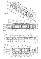
- Fig. 1 shows shows a raceway 1 for laying electrical conductors that is one of the known type, particularly one of the type that is made by extruding a synthetic plastics material and configured as a channel-shaped section made up of a bottom strip 2 that is flanked orthogonally by two equal opposite walls 3 that form at their free end a channel-shaped edge 4 for fitting a cover section (not shown), wherein the width of the bottom L and the height H of the walls can be variable, without said walls losing their specular symmetry with respect to a plane that is central and perpendicular to the bottom strip 2, all for the purpose of achieving a wide range of dimensions for raceways1.
- the object of the invention lies in the fact that on the top face of an inclined marginal area 5 at the top end of each wall 3 of raceway 1, which is tilted inwards and upwards, with relative specular symmetry with respect to a middle plane P perpendicular to bottom strip 2, a seating flap 6 is arranged that is parallel to said bottom strip 2 and which forms, with an extension 7 of said inclined marginal area 5 and with the channel-shaped edge 4, a tubular section 8 in cantilever arrangement from the free end 9 of which there emerges an anchoring wing 10 that is perpendicular to said bottom strip 2.
- the top portion of the free edge of walls 3 comprises marginal area 5 tilted towards the inside of raceway 1 with the aim of establishing a space 11 for locating the channel-shaped edge 4, which is formed by a straight portion 12 followed by a portion 13 arched towards the outside, which, as it is open towards said inclined marginal area 5 and projects over said inclined marginal area 5 without projecting out of it, is complementary to the edge of a closing cover for the raceway (not shown), while said straight portion 12 of channel-shaped edge 4, that emerges from said inclined marginal area 5, extends in a flat, horizontal seating flap 6 that emerges orthogonally from the back of said straight portion 12, so that its cantilever edge coincides together with the cantilever end of inclined marginal area 5 in a narrow, vertical slat 14 that extends into short anchoring wing 10 in cantilever arrangement towards bottom strip 2.
- a wedge shaped projection 15 is provided having its inclined side 16 tilted towards the centre of bottom strip 2 and its short side 17, which is parallel to the bottom portion of wall 3, lying in a plane Q which, while also being parallel to said wall 3, coincides with a small partition 18 that emerges from the inner face of inclined marginal area 5 on the free end of said wall 3 of raceway 1, and is parallel thereto.
- the short anchoring wing 10 that is in cantilever arrangement towards bottom strip 2 has an edge biselled as a convex curve.
- inclined marginal area 5 on the free end of walls 3, straight portion 12 of channel-shaped edge 4 and seating flap 6 define a hollow space 20 with a triangular cross-section.
- bottom strip 2 of raceway 1 can be provided with anchoring means 34, of a known type, to removably insert longitudinal compartment partitions 35 in which retainer 20 can be attached, fitting some parts thereof on top seamed edge 36 of said compartment partitions 35.
- a retainer 20 in a raceway 1 as above, is made up of an oblong single part 21 that has a "U"-shaped straight section and which is differentiated in a plurality of separable, longitudinal parts, with the two end parts 22 being the same and being provided with the same attachment means for attaching to the top ends of raceway 1, whereas the remaining inner parts 23, which have a different structure from that of the end parts 22, are provided with attachment means, which are different from those provided on said end parts 22, for attaching to the top seamed edges 36 of the compartment partitions 35 which may be arranged in raceway 1.
- the attachment means of end longitudinal parts 22 of oblong single part 21, as shown in Fig. 4 are made up of an elastic clamp arrangement that has two flat coplanar flanges 24 that are separate and in cantilever arrangement, and are complemented with a hooked elastic finger 25 facing the separation space between said flat flanges 24.
- the attachment means of inner parts 23, which, as can be seen in Fig. 8 , are functional after at least one of end parts 22 has been separated, are made up of simple cantilever arms 26 ending in open pressure clamps 27. Arms 26 are provided, at each end of inner parts 23, either arranged individually in the centre, or in pairs with one at each end of the width of said inner part 23. As can be seen in Figs. 2 to 5 , end parts 22 are also provided, on their inner end coinciding with the end of contiguous inner part 23, with the arms 26 described for inner parts 23. All such that arms 26 of each two contiguous parts are juxtaposed in an arrangement of three, both in the case of two contiguous inner parts 23 as in the case of one contiguous inner part 23 and end part 22.
- Each end part 22 and inner part 23 of oblong single part 21 comprises a wall fragment 28 corresponding to each branch of its "U"-shaped section and a bottom wall fragment 29 corresponding to the base of said "U"-shaped section, with each of said parts, end 22 or inner 23, being joined to the contiguous parts by wall fragments 28, and being provided with breakage lines 30 in the joining areas of the bottom fragment 29 of the base with the wall fragments 28 of the "U"-shaped section branches, and being provided with breakage bridges 31 between every two wall fragments 28.
- Oblong single part 21, in each wall fragment 28 of just one of the branches of the "U"-shaped section of said oblong single part 21, has a tab 32 projecting orthogonally from it and which is coplanar with the bottom fragment 29 of the base of said "U"-shaped straight section.
- Projecting tabs 32 have on their cantilever edge a slight, longitudinal arch 33 intended to fit between the tooth form 19 of small partition 18 of raceway 1 and the actual wall 3 thereof, as can be seen in Fig. 7 , in order to keep retainer 20 in the waiting position and to contain it without a specific function in the raceway 1 proper.
Landscapes
- Engineering & Computer Science (AREA)
- Architecture (AREA)
- Civil Engineering (AREA)
- Structural Engineering (AREA)
- Installation Of Indoor Wiring (AREA)
Applications Claiming Priority (2)
| Application Number | Priority Date | Filing Date | Title |
|---|---|---|---|
| ES200800861U ES1067771Y (es) | 2008-04-25 | 2008-04-25 | Canal para conductores electricos |
| ES200800870U ES1067776Y (es) | 2008-04-28 | 2008-04-28 | Retenedor de conductores electricos portados por canales |
Publications (1)
| Publication Number | Publication Date |
|---|---|
| EP2112732A1 true EP2112732A1 (fr) | 2009-10-28 |
Family
ID=40823043
Family Applications (1)
| Application Number | Title | Priority Date | Filing Date |
|---|---|---|---|
| EP09380080A Withdrawn EP2112732A1 (fr) | 2008-04-25 | 2009-04-17 | Chemin pour conducteurs électriques et dispositif de retenue pouvant être appliqué audit chemin |
Country Status (1)
| Country | Link |
|---|---|
| EP (1) | EP2112732A1 (fr) |
Cited By (1)
| Publication number | Priority date | Publication date | Assignee | Title |
|---|---|---|---|---|
| EP2806515A3 (fr) * | 2013-05-21 | 2015-04-29 | Unex Aparellaje Electrico S.L. | Ensemble de chemin de câbles conducteurs, chemin de cable et et élément de retenue propres à faire partie de cet ensemble |
Citations (6)
| Publication number | Priority date | Publication date | Assignee | Title |
|---|---|---|---|---|
| EP0094321A2 (fr) * | 1982-05-11 | 1983-11-16 | Aparellaje Electrico, S.A. | Dispositif pour l'installation de conduites destinées à loger des câbles électriques |
| ES2014604A6 (es) | 1989-04-14 | 1990-07-16 | Aparellaje Electrico Sa | Disposicion de acoplamiento de grapas rigidizadoras de canales para conductores electricos y similares y grapa correspondiente. |
| ES2027981T3 (es) | 1986-04-03 | 1992-07-01 | Tehalit Gmbh | Canal de conduccion de lineas. |
| EP1229623A1 (fr) * | 2001-02-06 | 2002-08-07 | Tehalit GmbH & Co. KG | Conduite de câbles |
| ES2174563T3 (es) | 1999-06-08 | 2002-11-01 | Tehalit Gmbh | Canal de tendido de lineas para el montaje frontal de aparatos de instalacion electrica. |
| ES2223347T3 (es) | 1999-07-01 | 2005-03-01 | TEHALIT GMBH & CO. KG | Bandeja de conduccion de cables. |
-
2009
- 2009-04-17 EP EP09380080A patent/EP2112732A1/fr not_active Withdrawn
Patent Citations (7)
| Publication number | Priority date | Publication date | Assignee | Title |
|---|---|---|---|---|
| EP0094321A2 (fr) * | 1982-05-11 | 1983-11-16 | Aparellaje Electrico, S.A. | Dispositif pour l'installation de conduites destinées à loger des câbles électriques |
| ES2027981T3 (es) | 1986-04-03 | 1992-07-01 | Tehalit Gmbh | Canal de conduccion de lineas. |
| ES2014604A6 (es) | 1989-04-14 | 1990-07-16 | Aparellaje Electrico Sa | Disposicion de acoplamiento de grapas rigidizadoras de canales para conductores electricos y similares y grapa correspondiente. |
| ES2174563T3 (es) | 1999-06-08 | 2002-11-01 | Tehalit Gmbh | Canal de tendido de lineas para el montaje frontal de aparatos de instalacion electrica. |
| ES2223347T3 (es) | 1999-07-01 | 2005-03-01 | TEHALIT GMBH & CO. KG | Bandeja de conduccion de cables. |
| EP1229623A1 (fr) * | 2001-02-06 | 2002-08-07 | Tehalit GmbH & Co. KG | Conduite de câbles |
| ES2266321T3 (es) | 2001-02-06 | 2007-03-01 | Tehalit Gmbh | Canal para cables. |
Cited By (1)
| Publication number | Priority date | Publication date | Assignee | Title |
|---|---|---|---|---|
| EP2806515A3 (fr) * | 2013-05-21 | 2015-04-29 | Unex Aparellaje Electrico S.L. | Ensemble de chemin de câbles conducteurs, chemin de cable et et élément de retenue propres à faire partie de cet ensemble |
Similar Documents
| Publication | Publication Date | Title |
|---|---|---|
| US4188019A (en) | Fencing construction | |
| EP1597445B1 (fr) | Systemes de revetement de sol | |
| US6023024A (en) | Partition device for a cableway | |
| US7348488B2 (en) | Raceway for electrical cables | |
| DE2757217A1 (de) | Bausatz zum errichten von waenden, ausstellungsanordnungen o.dgl. | |
| RU2457105C2 (ru) | Устройство для разрезания внутренней ячейки ячейкового устройства для закрывания архитектурных проемов, включающего в себя внутренние и наружные концентричные ячейки | |
| DE202010002324U1 (de) | Leiste und Leistenverbinder | |
| DE202008007362U1 (de) | Kühlgutabstellfach | |
| US6115984A (en) | Flexible runner | |
| EP2112732A1 (fr) | Chemin pour conducteurs électriques et dispositif de retenue pouvant être appliqué audit chemin | |
| EP0944786B1 (fr) | Chaine d'alimentation en energie | |
| US20220372753A1 (en) | Folded ceiling baffle | |
| JPH074998B2 (ja) | 製本方法及び製本用ストリツプ | |
| WO2012075535A1 (fr) | Panneau de clôture | |
| DE60204059T2 (de) | Lagerungsvorrichtung für die Latten eines Lattenrostes | |
| DE19840832C2 (de) | Halteklemme, insbesondere für einen für elektrische Einrichtungen bestimmten Kabelkanal | |
| DE1784142A1 (de) | Verbindungs- und Befestigungsmittel fuer aus Platten oder Baendern hergestellte Dach-Decken- und Wandverkleidungen | |
| ITBO20080203A1 (it) | Dispositivo a parete modulare. | |
| DE7109813U (de) | Anordnung zum Verlegen von elektrischen Leitungen | |
| DE69204149T2 (de) | Elektrische Anschlussbuchse, insbesondere für Kraftfahrzeuge. | |
| RU2003125966A (ru) | Соединительный элемент для направляющих занавеса, направляющая занавеса | |
| ES1067776U (es) | Retenedor de conductores electricos portados por canales. | |
| US11471165B2 (en) | Ligation clip cartridge | |
| DE7224449U (de) | Bauteile für den Deckenausbau | |
| DE3817475A1 (de) | Schraubenlose stossverbindung stumpf aneinanderstossender kabelrinnen |
Legal Events
| Date | Code | Title | Description |
|---|---|---|---|
| PUAI | Public reference made under article 153(3) epc to a published international application that has entered the european phase |
Free format text: ORIGINAL CODE: 0009012 |
|
| AK | Designated contracting states |
Kind code of ref document: A1 Designated state(s): AT BE BG CH CY CZ DE DK EE ES FI FR GB GR HR HU IE IS IT LI LT LU LV MC MK MT NL NO PL PT RO SE SI SK TR |
|
| 17P | Request for examination filed |
Effective date: 20100108 |
|
| 17Q | First examination report despatched |
Effective date: 20100224 |
|
| STAA | Information on the status of an ep patent application or granted ep patent |
Free format text: STATUS: THE APPLICATION IS DEEMED TO BE WITHDRAWN |
|
| 18D | Application deemed to be withdrawn |
Effective date: 20131101 |