EP2112676A2 - Device for magnetic position monitoring - Google Patents
Device for magnetic position monitoring Download PDFInfo
- Publication number
- EP2112676A2 EP2112676A2 EP09004826A EP09004826A EP2112676A2 EP 2112676 A2 EP2112676 A2 EP 2112676A2 EP 09004826 A EP09004826 A EP 09004826A EP 09004826 A EP09004826 A EP 09004826A EP 2112676 A2 EP2112676 A2 EP 2112676A2
- Authority
- EP
- European Patent Office
- Prior art keywords
- magnetic field
- sensor
- magnetic
- circuit
- signal
- Prior art date
- Legal status (The legal status is an assumption and is not a legal conclusion. Google has not performed a legal analysis and makes no representation as to the accuracy of the status listed.)
- Granted
Links
Images
Classifications
-
- H—ELECTRICITY
- H01—ELECTRIC ELEMENTS
- H01H—ELECTRIC SWITCHES; RELAYS; SELECTORS; EMERGENCY PROTECTIVE DEVICES
- H01H36/00—Switches actuated by change of magnetic field or of electric field, e.g. by change of relative position of magnet and switch, by shielding
- H01H36/0006—Permanent magnet actuating reed switches
- H01H36/0046—Limit switches, also fail-safe operation or anti-tamper considerations
-
- H—ELECTRICITY
- H03—ELECTRONIC CIRCUITRY
- H03K—PULSE TECHNIQUE
- H03K17/00—Electronic switching or gating, i.e. not by contact-making and –breaking
- H03K17/94—Electronic switching or gating, i.e. not by contact-making and –breaking characterised by the way in which the control signals are generated
- H03K17/945—Proximity switches
- H03K17/95—Proximity switches using a magnetic detector
- H03K17/9502—Measures for increasing reliability
-
- H—ELECTRICITY
- H03—ELECTRONIC CIRCUITRY
- H03K—PULSE TECHNIQUE
- H03K17/00—Electronic switching or gating, i.e. not by contact-making and –breaking
- H03K17/94—Electronic switching or gating, i.e. not by contact-making and –breaking characterised by the way in which the control signals are generated
- H03K17/945—Proximity switches
- H03K17/95—Proximity switches using a magnetic detector
- H03K17/9517—Proximity switches using a magnetic detector using galvanomagnetic devices
Definitions
- the locking element is equipped with a permanent magnet and its locking engagement element with a plurality of responsive to the magnetic field of the permanent magnet magnetic field sensors in the form of Hall elements.
- a monitoring circuit Based on the output signals of the spatially spaced-apart magnetic field sensors and of at least one reference variable assigned to the sensors, a monitoring circuit generates a monitoring signal characterizing the locking position or the unlocking position of the locking element.
- the monitoring circuit is operable with the casement closed in an initialization phase, in which it sets a reference size for each magnetic field sensor depending on the then generated output signals of the individual magnetic field sensors and writes them into a memory .
- the monitoring circuit compares the output signals of the magnetic sensors with the assigned reference variables and triggers an alarm if at least one sensor output signal lies outside a predetermined reference variable corridor.
- the output signals of the magnetic sensors can change even with properly locked latch element, for example, because the field strength of the permanent magnet as a result of aging decreases or because the window sash warps and thus changes the spatial relative position of the magnet and sensor.
- the monitoring circuit allows the stored reference variables to follow a change of the field strength detected by the magnetic sensors in the locking position at a predetermined rate of change or as a function of a time average of the sensor output signals.
- magnetoresistive sensors have been used as position, angle or magnetic field sensors, which are characterized by high precision of measurement, low power consumption and extremely small dimensions. They are based on the so-called “Anisotropic Magneto-Resistive Effect” (AMR) or on the “ Magneto-Resistive Giant Effect "(Giant Magneto Resistive) (GMR) and are for example in an article” Magnetoresistive sensors make mobile "the publication AUTOMOTIVE 7-8.2004 on pages 24-27 (Components).
- AMR isotropic Magneto-Resistive Effect
- GMR Magneto-Resistive Giant Effect
- the present invention is an opening detector of the type mentioned above with self-monitoring, which indicates a possible relative displacement of its position detecting components (magnetic part and / or sensor) with respect to a predetermined desired position, if the relative displacement is not due to the operational movement of the component carrying the object ( Door or window sash) is caused during operation.
- position detecting components magnetic part and / or sensor
- automatic drift correction is particularly in the position monitoring of a door or window sash a security risk, because by exploiting the drift correction over an extended period of time, an enlarged opening angle can be obscured and the monitoring device is manipulated.
- the invention characterized in claim 1 therefore a fundamentally different way.
- no Hall sensors based on the galvanomagnetic Hall effect in semiconductors but, for example, MR sensors based on a quantum mechanical magnetoresistive effect in ferromagnetic conductive thin films are used as magnetic field sensors, which exhibit a significantly higher magnetic field sensitivity and spatial accuracy compared to Hall sensors. a much lower power consumption and above all by a minimal space requirement. This not only changes the measured Magnetic field strength but also spatial displacements of magnetic field structures recognize very accurately.
- the present invention relates to a device according to the preamble of claim 1 for position monitoring of two relatively movable objects, in particular a window or door leaf or its locking on the one hand and a window or door frame on the other.
- the magnetic field sensor has at least one magnetoresistive sensor element, and the evaluation circuit also supplies a warning signal requesting the checking of the measuring device if said deviation lies between the nominal value range and the limit value.
- the invention triggered by the indication of a drift indication signal, eliminating the causes for the drift, for example, by eliminating these reasons by readjusting either the door or window sash or the sensor assembly at the next maintenance of the system , The risk of drift fogging or manipulability is avoided.
- the opening detector works properly (green may be displayed). If the deviation is below an optionally adjustable, yet uncritical limit value, this is indicated (for example, yellow), so that the position of the sensor components can be readjusted during the next maintenance cycle. If the deviation exceeds the limit value, an alarm is triggered (display red), because reliable position monitoring of the object (eg door leaf) is no longer guaranteed or the object is in an impermissible position. If the MR sensor reports that at least one predetermined magnetic field strength has been exceeded, this indicates that an attempt is being made to manipulate the monitoring system by approaching or applying a foreign magnet.
- the rest position and / or the path of movement of the permanent magnet and / or sensor are readjusted at the latest in the course of the next due inspection or maintenance of the opening detector.
- This can be done in various ways, for example by straightening the door or window sash, by realigning the example mounted in an eccentric mount sensor (see. DE 20 2006 015 541 U1 ), by placing an additional magnet on a the triggering magnetic part bearing locking bolt of a door or window fitting (see.
- the magnetic part As acting on the MR sensor magnetic part, as previously customary, serve a permanent magnet.
- the high sensitivity of MR sensors may make it possible to dispense with such a special magnet and instead to use at least one magnetic part, for example a ferromagnetic or soft magnetic, that is a magnetizable component, which can be an already existing magnetic field, e.g. the geomagnetic field, locally structured, in particular concentrated, so that a specific field structure for the MR sensor is recognizable.
- the magnetic part may be composed of a plurality of sections effecting a field coding.
- the opening detector If you want to check the proper operation of the opening detector not only a possible weakening of the magnetic field but also determine an offset, so you can, for example, in the range of an end position of the movable object several MR sensors spatially distributed around the desired path of the magnetic part or its end position arrange and determine by comparing the FeldStarmeßhong the individual sensors, whether, how much and in which direction the trajectory is shifted in this area. Again, a deviation beyond a predetermined limit by a warning signal, the maintenance personnel point out that a readjustment is advisable. If a mechanical readjustment of the object carrying the magnetic part is not possible, the deviation u.U. Compensate that the measurement signals of the individual MR sensors are weighted differently in the evaluation circuit.
- Utilizing the terrestrial magnetic field e.g. at the same opening degree of the window, determine whether the window has been pivoted or tilted to the open position.
- scalar quantities such as the magnetic field strength
- vector quantities such as the field direction.
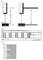
- the permanent magnet M is attached in the case of an opening detector on the door or window sash and can also be composed of several partial magnets. He moves with the door in the direction of the arrow P on the stationary on the door or window frame held magnetic field sensor S to and from this away; namely on a predetermined path of movement, which is curved in the case of a pivoting movement. The more the magnet M approaches the sensor S, the higher the magnitude of the magnetic field or the magnetic fields measured by it.
- the sensor S is connected either via a cable L or via an antenna A and a radio link to a stationary monitoring center.
- the sensor shown contains magnetic field-sensitive elements as one or more bridge circuits of magnetoresistive sensor elements.
- the designed as a microchip bridge circuit 1 is connected on the output side to a microcontroller 2, which forms an evaluation circuit for the measured magnetic field strength together with further arranged on the chip assemblies.
- a matching circuit 3 for connection to a signal transmission bus L or a driver circuit 3 for connection to a radio antenna A or an output stage 3 for feeding the measurement signals or signals derived therefrom into a multicore cable can be implemented for these components whose function can also be implemented in the microcontroller L belong.
- a protective circuit 4 can be provided to ensure electromagnetic compatibility EMC and a field 5 with solder pads for the line connection.
- a stabilized power supply 6 with battery or accumulator and charging circuit, optionally powered by radio, and alternatively a cable connection 7 for power and / or wired signal transmission available.
- An opening detector should normally detect if a window or door is actually closed and possibly locked.
- a permanent magnet arranged on or in the door leaf, upon reaching the closed position, switches over a reed contact attached to the door frame, which closes or interrupts a monitoring circuit.
- the closed position of a door is mechanically defined, namely when the door rests against the frame.
- the reed contact or in DE 195 18 527 provided Hall sensors used as a magnetic sensor magnetoresistive sensor, whose in the closed position the door generated Endlagensignal not only is a predetermined switching level exceeding switching signal.
- the output signal of the magnetoresistive field sensor is proportional both in the end position and in any other position of the magnet carried by the door to the prevailing at the field sensor magnetic field strength. If the door does not close, either because the drive is not working properly or because an obstacle prevents it from closing, the sensor will not deliver a limit signal, so that a corresponding display or alarm signal will be generated.
- the threshold value exceeds minimum, this means that the magnetic part and sensor in the closed position further apart are, as in proper relative position of the path of movement of the magnetic part relative to the position of the sensor. At least in this end position so the trajectory of the magnetic member is spatially shifted from its desired course.
- the evaluation circuit displays (eg green) as appropriate reaching the closed position of the door, but additionally or alternatively generates a deviation signal (eg yellow), which indicates that the relative position of the magnetic part trajectory and sensor position to each other changed from the original setting Has.
- This deviation indication causes a check of the magnetic part and / or sensor adjustment during the next maintenance cycle. If necessary, it is advisable to store the nominal magnetic field strength (n) in both end positions of the mobile object and to compare it with the currently measured values. For example, you can tell if the sash has warped or lowered.
- the switching distance at the approach of the magnet part and the sensor as well as the switching distance when removing the magnet part from the sensor and also the width of the permissible deviation range can be determined and set if necessary. Furthermore, by evaluating the actual magnetic field strength proportional sensor output signal can be determined whether, for example, in the train of a sensor manipulation, was tried by applying a foreign magnet to simulate a closed position of the door. After the installation of sensor and magnet can be because of the high sensitivity of magnetoresistive sensors measure the magnetic field strength in at least one tilted position of the window and store it as electrical size. If the window is then opened slowly during operation, it can be detected by continuously measuring the magnetic field strength as it passes through this tilting position.
- the zone 11 corresponds e.g. the nominal value of the magnetic field strength with the window closed (end position I). On both sides of this zone 11 there is a deviation zone 10 or 12 respectively. If a field strength value lying in one of these two contact zones is measured, then the monitoring system is notified of a window in the closed state (green). At the same time (or instead) it is indicated that, for example due to deformation of the window, the measured value in this (mechanically defined) end position I deviates from the actual desired value 11, but is still within a predetermined tolerance range 10,12. This display prompts the maintenance service, at the next maintenance cycle to check the function of this measuring point, in particular the relative position of the sensor and the magnetic part. Maybe the window or its storage has warped.
- zones 13 to 15 have the zones 13 to 15, this time with respect to a different end position II of the window, for example, the final position when fully opened or tilted window. Again, there is a deviation zone 13 or 15 on both sides of the setpoint zone 14. If a magnetic field strength lying in one of these two deviation zones is measured, a display as described above appears, which prompts for checking in the next maintenance cycle.
- the evaluation circuit connected to the sensor elements can recognize from the chronological order of the measured field strength values, for example 10, 11, 12 or 12, 11, 10, in which direction the setpoint value 11 is approached. This results in, for example, whether the magnetic part carried by the moving object moves in the switch-on direction or in the switch-off direction.
- zone 8 includes field strength values, which suggest that, for example, by placing a foreign magnet was tried to manipulate the measuring device, such as pretend a closed state of the window.
- a reading in alarm zone 9 indicates (red) that the window is open.
- the width and location of said zones and optionally other zones of fixed importance depends, as mentioned, on the circumstances of the case.
- the deviation zones associated with a setpoint zone may have different widths or it may even be provided on one side only of the setpoint zone a zone of permissible deviation.
- the invention can be modified in such a way that a reed contact is used as the magnetic sensor for end position detection, and the evaluation of the actual magnetic field strength measured by the MR sensor in the previously described manner is now used to monitor the function of this reed contact and its trajectory becomes.
- the calibration of the opening detector can determine the example of the respective tilt angle of the window dependent course of the magnetic field strength and possibly store it in the microcontroller, so that this can recognize during the opening or closing movement occurring magnetic or mechanical interference and bring to the display.
Abstract
Description
Es ist bekannt, die Schließ- oder Offenstellung eines Fenster- oder Türflügels bzw. die aktuelle Position der zugehörigen Verriegelungseinrichtung berührungsfrei mit Hilfe eines stationär am Rahmen angebrachten Magnetsensors zu erfassen, welcher mit einem am Tür- oder Fensterflügel angeordneten bzw. an einem Riegelbolzen befestigten Dauermagneten zusammenwirkt (vgl.z.B.
Des weiteren zeigt
Im Laufe der Zeit können sich die Ausgangssignale der Magnetsensoren auch bei ordnungsgemäß verriegeltem Riegelelement ändern, beispielsweise weil die Feldstärke des Dauermagneten infolge Alterung abnimmt oder weil sich der Fensterflügel verzieht und sich somit die räumliche Relativlage von Magnet und Sensor ändert. Um hier Abhilfe zu schaffen, sieht
Seit einigen Jahren werden als Positions-, Winkel- oder Magnetfeldsensoren magnetoresistive (MR) Sensoren eingesetzt, welche sich durch hohe Meßpräzision, geringen Stromverbrauch und äußerst kleine Abmessungen auszeichnen. Sie beruhen auf dem sog. "Anisotropen Magneto-Resistiven Effekt" (AMR) oder auf dem "
Ziel der vorliegenden Erfindung ist ein Öffnungsmelder der eingangs genannten Art mit Eigenüberwachung, welcher eine etwaige Relativverschiebung seiner die Position erfassenden Komponenten (Magnetteil und/oder Sensor) gegenüber einer vorgegebenen Sollposition anzeigt, wenn die Relativverschiebung nicht durch die betriebsbedingte Bewegung des die Komponenten tragenden Objekts (Tür- oder Fensterflügel) im Betrieb verursacht ist. Die in
Zur Lösung der genannten Aufgabe geht die im Anspruch 1 gekennzeichnete Erfindung deshalb einen grundsätzlich anderen Weg. Zum einen erfolgt keine automatische Driftkorrektur sondern eine Driftanzeige, sobald die Drift größer ist als ein vorgegebener Bereich. Andererseits werden keine auf dem galvanomagnetischen Hall-Effekt in Halbleitern beruhenden Hall-Sensoren, sondern z.B. auf einem quantenmechanischen magnetoresistiven Effekt in ferromagnetischen leitfähigen Dünnschichten basierende MR-Sensoren als Magnetfeldsensoren eingesetzt, welche sich gegenüber Hall-Sensoren durch eine wesentliche höhere Magnetfeldempfindlichkeit und räumliche Messgenauigkeit, eine viel geringere Stromaufnahme sowie vor allem durch einen minimalen Platzbedarf auszeichnen. Hiermit lassen sich nicht nur Änderungen der gemessenen Magnetfeldstärke sonder auch räumliche Verschiebungen von Magnetfeldstrukturen sehr genau erkennen.To solve the above problem, the invention characterized in claim 1 therefore a fundamentally different way. On the one hand, there is no automatic drift correction but a drift display as soon as the drift is greater than a specified range. On the other hand, no Hall sensors based on the galvanomagnetic Hall effect in semiconductors but, for example, MR sensors based on a quantum mechanical magnetoresistive effect in ferromagnetic conductive thin films are used as magnetic field sensors, which exhibit a significantly higher magnetic field sensitivity and spatial accuracy compared to Hall sensors. a much lower power consumption and above all by a minimal space requirement. This not only changes the measured Magnetic field strength but also spatial displacements of magnetic field structures recognize very accurately.
Ausgehend von der in
Gegenüber der in
Ist keine Abweichung vom Sollwert festzustellen, so arbeitet der Öffnungsmelder ordnungsgemäß (evtl. Anzeige grün). Liegt die Abweichung unterhalb eines, gegebenenfalls einstellbaren, noch unkritischen Grenzwertes, so wird dies angezeigt (z.B. gelb), damit die Lage der Sensorkomponenten beim nächsten Wartungszyklus nachjustiert werden kann. Überschreitet die Abweichung den Grenzwert, so wird Alarm ausgelöst (Anzeige rot), weil dann eine zuverlässige Positionsüberwachung des Objekts (z.B Türflügel) nicht mehr gewährleistet ist oder sich das Objekt in einer unzulässigen Stellung befindet. Meldet der MR-Sensor das Überschreiten wenigstens einer vorgebenen Magnetfeldstärke, so zeigt dies an, dass durch Annähern bzw. Auflegen eines Fremdmagneten versucht wird, die Überwachungsanlage zu manipulieren.If there is no deviation from the setpoint, the opening detector works properly (green may be displayed). If the deviation is below an optionally adjustable, yet uncritical limit value, this is indicated (for example, yellow), so that the position of the sensor components can be readjusted during the next maintenance cycle. If the deviation exceeds the limit value, an alarm is triggered (display red), because reliable position monitoring of the object (eg door leaf) is no longer guaranteed or the object is in an impermissible position. If the MR sensor reports that at least one predetermined magnetic field strength has been exceeded, this indicates that an attempt is being made to manipulate the monitoring system by approaching or applying a foreign magnet.
Lässt der MR-Sensor eine unzulässige Schwächung oder Verlagerung des Magnetfelds bzw. der Magnetfelder erkennen, so werden spätestens im Zuge der nächstfälligen Inspektion oder Wartung des Öffnungsmelders die Ruheposition und/oder die Bewegungsbahn von Dauermagnet und/oder Sensor nachjustiert. Dies kann auf verschiedene Weise geschehen, beispielsweise durch Richten des Tür- oder Fensterflügels, durch Neuausrichten des beispielsweise in einer Exzenterhalterung gelagerten Sensors (vgl.
Als auf den MR-Sensor einwirkendes Magnetteil kann, wie bislang üblich, ein Dauermagnet dienen. Die hohe Empfindlichkeit von MR-Sensoren kann es aber erlauben, auf einen solchen besonderen Magneten zu verzichten und stattdessen wenigstens ein Magnetteil, beispielsweise ein ferromagnetisches oder weichmagnetisches, also ein magnetisierbares Bauteil zu verwenden, welches ein ohnehin vorhandenes Magnetfeld, z.B. das erdmagnetische Feld, örtlich strukturiert, insbesondere konzentriert, so dass eine bestimmte Feldstruktur für den MR-Sensor erkennbar wird. Um die Messbarkeit einer solchen Feldstruktur zu erleichtern, kann das Magnetteil aus mehreren, eine Feldkodierung bewirkenden Sektionen zusammengesetzt sein.As acting on the MR sensor magnetic part, as previously customary, serve a permanent magnet. The high sensitivity of MR sensors, however, may make it possible to dispense with such a special magnet and instead to use at least one magnetic part, for example a ferromagnetic or soft magnetic, that is a magnetizable component, which can be an already existing magnetic field, e.g. the geomagnetic field, locally structured, in particular concentrated, so that a specific field structure for the MR sensor is recognizable. In order to facilitate the measurability of such a field structure, the magnetic part may be composed of a plurality of sections effecting a field coding.
Will man zur Überprüfung der ordentlichen Arbeitsweise des Öffnungsmelders nicht nur eine eventuelle Schwächung des Magnetfelds sondern auch einen Versatz desselben ermitteln, so kann man beispielsweise im Bereich einer Endlage des beweglichen Objekts mehrere MR-Sensoren um die Soll-Bewegungsbahn des Magnetteils oder dessen Endposition räumlich verteilt anordnen und durch Vergleich der Feldstärkemeßwerte der einzelnen Sensoren feststellen, ob, wie stark und in welche Richtung die Bewegungsbahn in diesem Bereich verschoben ist. Auch hier kann eine jenseits eines vorgegebenen Grenzwertes liegende Abweichung durch ein Warnsignal das Wartungspersonal darauf hinweisen, dass einen Nachjustierung ratsam ist. Ist eine mechanische Nachjustierung des das Magnetteil tragenden Objekts nicht möglich, kann man die Abweichung u.U. dadurch kompensieren, dass die Meßsignale der einzelnen MR-Sensoren in der Auswerteschaltung unterschiedlich gewichtet werden. Unter Ausnutzung des erdmagnetischen Feldes lässt sich z.B. bei gleichem Öffnungsgrad des Fensters feststellen, ob das Fenster in die Offenstellung geschwenkt oder gekippt wurde. Generell lassen sich dank der äußerst geringen Abmessungen von MR-Sensoren durch diese nicht nur skalare Größen, wie die Magnetfeldstärke, sondern durch den Einsatz mehrerer solcher Sensoren in gedrängter Anordnung auch Vektorgrößen, wie die Feldrichtung ermitteln.If you want to check the proper operation of the opening detector not only a possible weakening of the magnetic field but also determine an offset, so you can, for example, in the range of an end position of the movable object several MR sensors spatially distributed around the desired path of the magnetic part or its end position arrange and determine by comparing the Feldstärkemeßwerte the individual sensors, whether, how much and in which direction the trajectory is shifted in this area. Again, a deviation beyond a predetermined limit by a warning signal, the maintenance personnel point out that a readjustment is advisable. If a mechanical readjustment of the object carrying the magnetic part is not possible, the deviation u.U. Compensate that the measurement signals of the individual MR sensors are weighted differently in the evaluation circuit. Utilizing the terrestrial magnetic field, e.g. at the same opening degree of the window, determine whether the window has been pivoted or tilted to the open position. In general, thanks to the extremely small dimensions of MR sensors, not only scalar quantities, such as the magnetic field strength, but also the use of several such sensors in a crowded array can be used to determine vector quantities, such as the field direction.
Vorteilhafte Ausgestaltungen und Weiterbildungen der Erfindung ergeben sich aus den Unteransprüchen. Sie wird nachfolgend anhand in der Zeichnung schematisch wiedergegebener Ausführungsbeispiele erläutert. Darin zeigt
- Fig.
- 1 einen aus Magnetteil und Magnetfeldsensor bestehenden Öffnungsmelder, wenn sich Magnetteil und Sensor in paralleler Ausrichtung gegenüberstehen;
- Fig.2
- einen Öffnungsmelder, bei dem sich Magnetteil und Sensor stirnseitig gegenüberstehen;
- Fig.3
- die Komponenten eines Magnetfeldsensors;
- Fig.4
- die Zuordnung einzelner Betriebszustände des zu überwachenden Objekts und des Öffnungsmelders zu den gemessenen Werten der magnetischen Feldstärke H.
- FIG.
- 1 an opening detector consisting of a magnetic part and a magnetic field sensor when the magnetic part and the sensor face each other in parallel alignment;
- Fig.2
- an opening detector, in which the magnetic part and the sensor face each other;
- Figure 3
- the components of a magnetic field sensor;
- Figure 4
- the assignment of individual operating states of the object to be monitored and the opening detector to the measured values of the magnetic field strength H.
Der Dauermagnet M ist im Fall eines Öffnungsmelders am Tür- oder Fensterflügel befestigt und kann auch aus mehreren Teilmagneten zusammengesetzt sein. Er bewegt sich mit dem Türflügel in Richtung des Pfeils P auf den ortsfest am Tür- bzw. Fensterrahmen gehaltenen Magnetfeldsensor S zu bzw. von diesem weg; und zwar auf einer vorgebenen Bewegungsbahn, welche im Fall einer Schwenkbewegung gekrümmt ist. Je mehr sich der Magnet M dem Sensor S nähert, umso höher ist die von diesem gemessene Stärke des Magnetfeldes bzw. der Magnetfelder. Der Sensor S steht entweder über ein Kabel L oder über eine Antenne A und eine Funkstrecke mit einer ortsfesten Überwachungszentrale in Verbindung.The permanent magnet M is attached in the case of an opening detector on the door or window sash and can also be composed of several partial magnets. He moves with the door in the direction of the arrow P on the stationary on the door or window frame held magnetic field sensor S to and from this away; namely on a predetermined path of movement, which is curved in the case of a pivoting movement. The more the magnet M approaches the sensor S, the higher the magnitude of the magnetic field or the magnetic fields measured by it. The sensor S is connected either via a cable L or via an antenna A and a radio link to a stationary monitoring center.
Der in
Ein Öffnungmelder soll normalerweise feststellen, ob ein Fenster oder eine Tür tatsächlich geschlossen und gegebenfalls auch verriegelt ist. Hierzu schaltet im Stand der Technik ein am oder im Türflügel angeordneter Dauermagnet beim Erreichen der Schließlage einen am Türrahmen angebrachten Reed-Kontakt um, welcher einen Überwachungsstromkreis schließt bzw. unterbricht. Die Schließlage einer Tür wird mechanisch definiert, nämlich wenn die Tür am Rahmen anliegt. Nach der Erfindung wird anstelle des Reed-Kontakts bzw. der in
Geht die Tür mechanisch ordnungsgemäß in den Schließzustand und liegt das vom Magnetsensor gelieferte Signal zwar oberhalb des Ansprechwerts des Endlagensignals aber gleichwohl unterhalb eines vorgegebenen, im Microcontroller gespeicherten, den Ansprechwert übersteigenden Mindestwerts, so bedeutet das, dass Magnetteil und Sensor in der Schließlage weiter voneinander entfernt sind, als bei ordnungsgemäßer Relativlage der Bewegungsbahn des Magnetteils gegenüber der Position des Sensors. Zumindest in dieser Endlage ist also die Bewegungsbahn des Magnetteils gegenüber ihrem Sollverlauf räumlich verschoben. Die Auswerteschaltung zeigt dann (z.B. grün) zutreffender Weise das Erreichen der Schließstellung der Tür an, erzeugt aber zusätzlich oder alternativ ein Abweichungssignal (z.B. gelb), welches erkennen läßt, dass sich die Relativlage von Magnetteil-Bewegungsbahn und Sensorposition zueinander gegenüber der ursprünglichen Einstellung geändert hat. Diese Abweichungsanzeige veranlasst eine Überprüfung von Magnetteil- und/oder Sensor-Justierung beim nächsten Wartungszyklus. Gegebenenfalls ist es ratsam, die Soll-Magnetfeldstärke(n) in beiden Endlagen des beweglichen Objekts abzuspeichern und mit den aktuell gemessenen Werten zu vergleichen. Dann erkennt man z.B., ob sich der Fensterflügel verzogen oder gesenkt hat.If the door mechanically properly in the closed state and the signal supplied by the magnetic sensor is indeed above the threshold of the Endlagensignals but below a predetermined, stored in the microcontroller, the threshold value exceeding minimum, this means that the magnetic part and sensor in the closed position further apart are, as in proper relative position of the path of movement of the magnetic part relative to the position of the sensor. At least in this end position so the trajectory of the magnetic member is spatially shifted from its desired course. The evaluation circuit then displays (eg green) as appropriate reaching the closed position of the door, but additionally or alternatively generates a deviation signal (eg yellow), which indicates that the relative position of the magnetic part trajectory and sensor position to each other changed from the original setting Has. This deviation indication causes a check of the magnetic part and / or sensor adjustment during the next maintenance cycle. If necessary, it is advisable to store the nominal magnetic field strength (n) in both end positions of the mobile object and to compare it with the currently measured values. For example, you can tell if the sash has warped or lowered.
Nach der gleichen Methode lassen sich der Schaltabstand bei der Annäherung von Magnetteil und Sensor sowie der Schaltabstand beim Entfernen des Magnetteils vom Sensor und auch die Breite des zulässigen Abweichungsbereichs ermitteln und ggf. einstellen. Des weiteren kann durch Auswerten des der tatsächlichen Magnetfeldstärke proportionalen Sensor-Ausgangssignals festgestellt werden, ob beispielsweise im Zug einer Sensormanipulation, durch Auflegen eines Fremdmagneten versucht wurde, eine Schließstellung der Tür vorzutäuschen. Nach der Installation von Sensor und Magnet kann man wegen der hohen Empfindlichkeit von magnetoresistiven Sensoren die Magnetfeldstärke in wenigstens einer Kipplage des Fensters messen und als elektrische Größe abspeichern. Wird dann im Betrieb das Fenster langsam geöffnet, so lässt sich durch kontinuierliches Messen der Magnetfeldstärke erkennen, wenn es diese Kipplage durchläuft.Using the same method, the switching distance at the approach of the magnet part and the sensor as well as the switching distance when removing the magnet part from the sensor and also the width of the permissible deviation range can be determined and set if necessary. Furthermore, by evaluating the actual magnetic field strength proportional sensor output signal can be determined whether, for example, in the train of a sensor manipulation, was tried by applying a foreign magnet to simulate a closed position of the door. After the installation of sensor and magnet can be because of the high sensitivity of magnetoresistive sensors measure the magnetic field strength in at least one tilted position of the window and store it as electrical size. If the window is then opened slowly during operation, it can be detected by continuously measuring the magnetic field strength as it passes through this tilting position.
In
Die Zone 11 entspricht z.B. dem Sollwert der Magnetfeldstärke bei geschlossenem Fenster (Endlage I). Zu beiden Seiten dieser Zone 11 befindet sich je eine Abweichungszone 10 bzw. 12. Wird ein in einer dieser beiden Anweichungszonen liegender Feldstärkewert gemessen, so wird zwar der Überwachungsanlage ein Fenster im Schließzustand gemeldet (grün). Zugleich (oder statt dessen) wird angezeigt, dass beispielsweise infolge Verformung des Fensters der Meßwert in dieser (mechanisch definierten) Endlage I vom eigentlichen Sollwert 11 abweicht, allerdings noch innerhalb eines vorgegebenen Toleranzkorridors 10,12 liegt. Diese Anzeige fordert den Wartungsdienst auf, beim nächsten Wartungszyklus die Funktion dieser Meßstelle, inbesondere die relative Lage von Sensor und Magnetteil zu überprüfen. Vielleicht hat sich das Fenster oder seine Lagerung verzogen.The
Eine ähnliche Bedeutung haben die Zonen 13 bis 15, diesmal bezogen auf eine andere Endlage II des Fensters, beispielsweise die Endlage bei voll göffnetem bzw. gekipptem Fenster. Auch hier liegt zu beiden Seiten der Sollwertzone 14 je eine Abweichungszone 13 bzw. 15. Wird eine in einer diesere beiden Abweichungszonen liegende Magnetfeldstärke gemessen, so erscheint eine, wie zuvor beschriebene Anzeige, welche zur Überprüfung im nächsten Wartungszyklus auffordert.A similar meaning have the zones 13 to 15, this time with respect to a different end position II of the window, for example, the final position when fully opened or tilted window. Again, there is a deviation zone 13 or 15 on both sides of the
Die an die Sensorelemente angeschlossene Auswerteschaltung kann aus der zeitlichen Reihenfolge der gemessenen Feldstärkewerte, also z.B. 10,11,12 oder 12,11,10 erkennen, in welcher Richtung der Sollwert 11 angefahren wird. Daraus ergibt sich beispielsweise, ob sich das vom beweglichen Objekt getragene Magnetteil in Einschaltrichtung oder in Abschaltrichtung bewegt.The evaluation circuit connected to the sensor elements can recognize from the chronological order of the measured field strength values, for example 10, 11, 12 or 12, 11, 10, in which direction the
Eine weitere, ebenfalls nur schematisch angedeutete Zone 8 umfasst Feldstärkewerte, welche darauf schließen lassen, dass beispielsweise durch Auflegen eine Fremdmagneten versucht wurde, die Meßvorrichtung zu manipulieren, etwa einen Schließzustand des Fensters vorzutäuschen.Another, also indicated only schematically zone 8 includes field strength values, which suggest that, for example, by placing a foreign magnet was tried to manipulate the measuring device, such as pretend a closed state of the window.
Schließlich zeigt ein in der Alarmzone 9 liegender Meßwert an (rot), dass das Fenster offen ist. Die Breite und Lage der genannten Zonen sowie gegebenenfalls weiterer Zonen mit fest zugeordneter Bedeutung hängt, wie erwähnt, von den Gegebenheiten des Einzelfalls ab. Die einer Sollwertzone zugeordneten Abweichungszonen können unterschiedlich breit oder es kann überhaupt nur auf einer Seite der Sollwertzone eine Zone zulässiger Abweichung vorgesehen sein.Finally, a reading in alarm zone 9 indicates (red) that the window is open. The width and location of said zones and optionally other zones of fixed importance depends, as mentioned, on the circumstances of the case. The deviation zones associated with a setpoint zone may have different widths or it may even be provided on one side only of the setpoint zone a zone of permissible deviation.
Die Erfindung kann im Bedarfsfall dahingehend abgewandelt werden, dass zur Endlagenerkennung wie bisher üblich ein Reed-Kontakt als Magnetsensor eingesetzt wird und die Auswertung der vom MR-Sensor gemessenen aktuellen Magnetfeldstärke in der zuvor geschilderten Weise nunmehr zur Funktionsüberwachung dieses Reed-Kontakts und seiner Bewegungsbahn herangezogen wird. Während der Kalibrierung des Öffnungsmelders kann man den beispielsweise vom jeweiligen Kippwinkel des Fensters abhängigen Verlauf der Magnetfeldstärke ermitteln und ggf. im Microcontroller abspeichern, so dass dieser während der Öfnnungs- oder Schließbewegung auftretende magnetische oder mechanische Störungen erkennen und zur Anzeige bringen kann.If necessary, the invention can be modified in such a way that a reed contact is used as the magnetic sensor for end position detection, and the evaluation of the actual magnetic field strength measured by the MR sensor in the previously described manner is now used to monitor the function of this reed contact and its trajectory becomes. During the calibration of the opening detector can determine the example of the respective tilt angle of the window dependent course of the magnetic field strength and possibly store it in the microcontroller, so that this can recognize during the opening or closing movement occurring magnetic or mechanical interference and bring to the display.
Claims (14)
dadurch gekennzeichnet, dass
characterized in that
Priority Applications (1)
| Application Number | Priority Date | Filing Date | Title |
|---|---|---|---|
| PL09004826T PL2112676T3 (en) | 2008-04-03 | 2009-04-01 | Device for magnetic position monitoring |
Applications Claiming Priority (1)
| Application Number | Priority Date | Filing Date | Title |
|---|---|---|---|
| DE102008017479A DE102008017479A1 (en) | 2008-04-03 | 2008-04-03 | Device for magnetic position monitoring |
Publications (3)
| Publication Number | Publication Date |
|---|---|
| EP2112676A2 true EP2112676A2 (en) | 2009-10-28 |
| EP2112676A3 EP2112676A3 (en) | 2010-07-14 |
| EP2112676B1 EP2112676B1 (en) | 2013-03-20 |
Family
ID=40756515
Family Applications (1)
| Application Number | Title | Priority Date | Filing Date |
|---|---|---|---|
| EP09004826A Active EP2112676B1 (en) | 2008-04-03 | 2009-04-01 | Device for magnetic position monitoring |
Country Status (4)
| Country | Link |
|---|---|
| EP (1) | EP2112676B1 (en) |
| DE (1) | DE102008017479A1 (en) |
| ES (1) | ES2412706T3 (en) |
| PL (1) | PL2112676T3 (en) |
Cited By (5)
| Publication number | Priority date | Publication date | Assignee | Title |
|---|---|---|---|---|
| EP3159464B1 (en) | 2015-09-02 | 2019-08-07 | Siegenia-Aubi KG | Locking device with assembly for monitoring the locking state |
| CN111007760A (en) * | 2019-11-26 | 2020-04-14 | 山东中创软件商用中间件股份有限公司 | Machine room safety monitoring device and machine room safety monitoring system |
| EP3239944B1 (en) * | 2016-04-28 | 2021-01-13 | Insta GmbH | Device for detecting the position of a magnet |
| CN112542817A (en) * | 2019-09-20 | 2021-03-23 | 西门子股份公司 | Circuit breaker and mobile device |
| CN112542817B (en) * | 2019-09-20 | 2024-04-12 | 西门子股份公司 | Circuit breaker and mobile device |
Families Citing this family (4)
| Publication number | Priority date | Publication date | Assignee | Title |
|---|---|---|---|---|
| DE102016123574A1 (en) | 2016-12-06 | 2018-06-07 | Maco Technologie Gmbh | safety device |
| DE102017212052A1 (en) * | 2017-07-13 | 2019-01-17 | Zf Friedrichshafen Ag | Inductive position determination |
| DE102017118388A1 (en) * | 2017-08-11 | 2019-02-14 | Abus Security-Center Gmbh & Co. Kg | Retrofit burglary detection unit |
| DE102021208795A1 (en) | 2021-08-11 | 2023-02-16 | Roto Frank Dachsystem-Technologie GmbH | Method for operating a sensor arrangement for a building closure element, corresponding sensor arrangement and building closure element with a sensor arrangement |
Citations (6)
| Publication number | Priority date | Publication date | Assignee | Title |
|---|---|---|---|---|
| DE19518527A1 (en) | 1995-05-19 | 1996-11-21 | Winkhaus Fa August | Monitorable locking arrangement for a window or a door or the like |
| DE19903468C1 (en) | 1999-01-29 | 2001-01-11 | Elektro Special Bedarf Link Gm | Opening detector for intruder alarm installation has 2 coaxial Reed contacts with different magnetic sensitivities used as detector contact and security contact |
| DE20014841U1 (en) | 2000-08-26 | 2002-01-17 | Elektro Special Bedarf Link Gm | Magnet-operated detector with two reed contacts |
| DE19914568C2 (en) | 1999-03-31 | 2003-10-09 | Elektro Special Bedarf Link Gm | Magnetically operated detector with reed contact |
| DE202006015541U1 (en) | 2006-10-09 | 2006-12-21 | Link Gmbh | Door and window frame cylindrical magnetic contact sensor has housing that can be rotated inside hollow screw and is secured by cover and spring ring |
| DE102005058405A1 (en) | 2005-12-07 | 2007-06-14 | Link Gmbh | Magnetic position monitoring device for locking pin of door or window has auxiliary magnet that is arranged on magnet tap having magnet that cooperates with magnet sensor |
Family Cites Families (3)
| Publication number | Priority date | Publication date | Assignee | Title |
|---|---|---|---|---|
| US5534849A (en) * | 1993-08-11 | 1996-07-09 | Sentrol, Inc. | Time multiplexed, false alarm resistant magnetically actuated security system |
| DE10349937B4 (en) * | 2003-10-24 | 2016-03-17 | Windhorst Beteiligungsgesellschaft Mbh | Device for the contactless detection of switching positions in motor vehicle locking systems |
| DE102005018826B3 (en) * | 2005-04-22 | 2006-10-05 | Robert Seuffer Gmbh & Co. Kg | Closing unit e.g. window sash, position e.g. opening, detecting device, has latch whose respective position within fitting are detected with magnetic field strength of permanent magnetic field measured in two space perpendicular directions |
-
2008
- 2008-04-03 DE DE102008017479A patent/DE102008017479A1/en not_active Ceased
-
2009
- 2009-04-01 ES ES09004826T patent/ES2412706T3/en active Active
- 2009-04-01 PL PL09004826T patent/PL2112676T3/en unknown
- 2009-04-01 EP EP09004826A patent/EP2112676B1/en active Active
Patent Citations (6)
| Publication number | Priority date | Publication date | Assignee | Title |
|---|---|---|---|---|
| DE19518527A1 (en) | 1995-05-19 | 1996-11-21 | Winkhaus Fa August | Monitorable locking arrangement for a window or a door or the like |
| DE19903468C1 (en) | 1999-01-29 | 2001-01-11 | Elektro Special Bedarf Link Gm | Opening detector for intruder alarm installation has 2 coaxial Reed contacts with different magnetic sensitivities used as detector contact and security contact |
| DE19914568C2 (en) | 1999-03-31 | 2003-10-09 | Elektro Special Bedarf Link Gm | Magnetically operated detector with reed contact |
| DE20014841U1 (en) | 2000-08-26 | 2002-01-17 | Elektro Special Bedarf Link Gm | Magnet-operated detector with two reed contacts |
| DE102005058405A1 (en) | 2005-12-07 | 2007-06-14 | Link Gmbh | Magnetic position monitoring device for locking pin of door or window has auxiliary magnet that is arranged on magnet tap having magnet that cooperates with magnet sensor |
| DE202006015541U1 (en) | 2006-10-09 | 2006-12-21 | Link Gmbh | Door and window frame cylindrical magnetic contact sensor has housing that can be rotated inside hollow screw and is secured by cover and spring ring |
Non-Patent Citations (1)
| Title |
|---|
| "Magneto-Resistiven Rieseneffekt" (Giant Magneto Resistive) (GMR) und sind beispielsweise in einem Aufsatz "Magnetoresistive Sensoren machen mobil", DRUCKSCHRIFT AUTOMOTIVE, July 2004 (2004-07-01), pages 24 - 27 |
Cited By (6)
| Publication number | Priority date | Publication date | Assignee | Title |
|---|---|---|---|---|
| EP3159464B1 (en) | 2015-09-02 | 2019-08-07 | Siegenia-Aubi KG | Locking device with assembly for monitoring the locking state |
| EP3159464B2 (en) † | 2015-09-02 | 2022-11-09 | Siegenia-Aubi KG | Assembly for monitoring a closure |
| EP3239944B1 (en) * | 2016-04-28 | 2021-01-13 | Insta GmbH | Device for detecting the position of a magnet |
| CN112542817A (en) * | 2019-09-20 | 2021-03-23 | 西门子股份公司 | Circuit breaker and mobile device |
| CN112542817B (en) * | 2019-09-20 | 2024-04-12 | 西门子股份公司 | Circuit breaker and mobile device |
| CN111007760A (en) * | 2019-11-26 | 2020-04-14 | 山东中创软件商用中间件股份有限公司 | Machine room safety monitoring device and machine room safety monitoring system |
Also Published As
| Publication number | Publication date |
|---|---|
| DE102008017479A1 (en) | 2009-10-15 |
| PL2112676T3 (en) | 2014-04-30 |
| ES2412706T3 (en) | 2013-07-12 |
| EP2112676B1 (en) | 2013-03-20 |
| EP2112676A3 (en) | 2010-07-14 |
Similar Documents
| Publication | Publication Date | Title |
|---|---|---|
| EP2112676B1 (en) | Device for magnetic position monitoring | |
| DE102005059538B4 (en) | Hinge sensor | |
| DE202006013335U1 (en) | anti-trap | |
| DE102006044778A1 (en) | Clamping protection device for door i.e. sliding door, or flap of motor vehicle, has capaciflectors arranged as sensor at stop edge and line shaped closing edge of door or flap, where closing edge moves on stop edge | |
| EP2371062B1 (en) | Capacitive proximity sensor having a shielding electrode and a diagnostic electrode | |
| EP3159464B2 (en) | Assembly for monitoring a closure | |
| DE102013001066A1 (en) | Capacitive proximity sensor | |
| EP2038503B1 (en) | Passage gate | |
| EP1979202B1 (en) | Method and monitoring system for closing covers | |
| DE102016125235A1 (en) | Angle of rotation sensor system and method | |
| EP2711905B1 (en) | Reporting system | |
| EP4041969B1 (en) | Switchgear cabinet having a switchgear cabinet door that comprises a door status sensor | |
| AT512180B1 (en) | HANG CASTLE | |
| EP3500763A1 (en) | Screw connection having a monitoring device | |
| EP2775625B1 (en) | Capacitive position switch | |
| EP3516141A2 (en) | Electromechanical closure having a rotary latch arrangement with an evaluatable door contact for controlling a display device such as a led module | |
| DE102013214425A1 (en) | Magnetoresistive proximity switch used in assembly for sensing position of metering piston in lubricant distributor, has a magnetic angle sensor to provide output signal depending on change in magnetic field direction caused by target | |
| EP3670794A1 (en) | Door assembly and method for operating a door assembly | |
| DE19826850C2 (en) | Arrangement for the position detection of an object | |
| DE102009057256A1 (en) | Sensor unit and building monitoring system with such sensor units | |
| EP2372665B1 (en) | Sensor unit, window and building monitoring system with such sensor units | |
| DE202020101348U1 (en) | Condition monitoring device for windows and doors | |
| EP4124832A1 (en) | Monitoring device for monitoring the position of a building element and method for monitoring the position of a building element | |
| DE19931977A1 (en) | Device for detecting lock cracks on sheet piles, piles and the like | |
| DE102005010692A1 (en) | Sensor for motor vehicle has reference sensor for recording and monitoring of variable disturbance of sensor and by recording variable disturbance of measuring signal of sensor, system is put in secure and given state |
Legal Events
| Date | Code | Title | Description |
|---|---|---|---|
| PUAI | Public reference made under article 153(3) epc to a published international application that has entered the european phase |
Free format text: ORIGINAL CODE: 0009012 |
|
| AK | Designated contracting states |
Kind code of ref document: A2 Designated state(s): AT BE BG CH CY CZ DE DK EE ES FI FR GB GR HR HU IE IS IT LI LT LU LV MC MK MT NL NO PL PT RO SE SI SK TR |
|
| PUAL | Search report despatched |
Free format text: ORIGINAL CODE: 0009013 |
|
| RIC1 | Information provided on ipc code assigned before grant |
Ipc: H01H 36/00 20060101AFI20090622BHEP Ipc: H03K 17/95 20060101ALI20100531BHEP |
|
| AK | Designated contracting states |
Kind code of ref document: A3 Designated state(s): AT BE BG CH CY CZ DE DK EE ES FI FR GB GR HR HU IE IS IT LI LT LU LV MC MK MT NL NO PL PT RO SE SI SK TR |
|
| AX | Request for extension of the european patent |
Extension state: AL BA RS |
|
| RAP1 | Party data changed (applicant data changed or rights of an application transferred) |
Owner name: LINK GMBH |
|
| 17P | Request for examination filed |
Effective date: 20110111 |
|
| GRAP | Despatch of communication of intention to grant a patent |
Free format text: ORIGINAL CODE: EPIDOSNIGR1 |
|
| RIC1 | Information provided on ipc code assigned before grant |
Ipc: H03K 17/95 20060101ALI20120928BHEP Ipc: H01H 36/00 20060101AFI20120928BHEP |
|
| GRAS | Grant fee paid |
Free format text: ORIGINAL CODE: EPIDOSNIGR3 |
|
| GRAA | (expected) grant |
Free format text: ORIGINAL CODE: 0009210 |
|
| AK | Designated contracting states |
Kind code of ref document: B1 Designated state(s): AT BE BG CH CY CZ DE DK EE ES FI FR GB GR HR HU IE IS IT LI LT LU LV MC MK MT NL NO PL PT RO SE SI SK TR |
|
| REG | Reference to a national code |
Ref country code: GB Ref legal event code: FG4D Free format text: NOT ENGLISH |
|
| REG | Reference to a national code |
Ref country code: CH Ref legal event code: EP |
|
| REG | Reference to a national code |
Ref country code: IE Ref legal event code: FG4D Free format text: LANGUAGE OF EP DOCUMENT: GERMAN |
|
| REG | Reference to a national code |
Ref country code: AT Ref legal event code: REF Ref document number: 602525 Country of ref document: AT Kind code of ref document: T Effective date: 20130415 |
|
| REG | Reference to a national code |
Ref country code: DE Ref legal event code: R096 Ref document number: 502009006513 Country of ref document: DE Effective date: 20130516 |
|
| REG | Reference to a national code |
Ref country code: SE Ref legal event code: TRGR |
|
| REG | Reference to a national code |
Ref country code: ES Ref legal event code: FG2A Ref document number: 2412706 Country of ref document: ES Kind code of ref document: T3 Effective date: 20130712 |
|
| PG25 | Lapsed in a contracting state [announced via postgrant information from national office to epo] |
Ref country code: LT Free format text: LAPSE BECAUSE OF FAILURE TO SUBMIT A TRANSLATION OF THE DESCRIPTION OR TO PAY THE FEE WITHIN THE PRESCRIBED TIME-LIMIT Effective date: 20130320 Ref country code: NO Free format text: LAPSE BECAUSE OF FAILURE TO SUBMIT A TRANSLATION OF THE DESCRIPTION OR TO PAY THE FEE WITHIN THE PRESCRIBED TIME-LIMIT Effective date: 20130620 Ref country code: BG Free format text: LAPSE BECAUSE OF FAILURE TO SUBMIT A TRANSLATION OF THE DESCRIPTION OR TO PAY THE FEE WITHIN THE PRESCRIBED TIME-LIMIT Effective date: 20130620 |
|
| REG | Reference to a national code |
Ref country code: LT Ref legal event code: MG4D |
|
| PG25 | Lapsed in a contracting state [announced via postgrant information from national office to epo] |
Ref country code: SI Free format text: LAPSE BECAUSE OF FAILURE TO SUBMIT A TRANSLATION OF THE DESCRIPTION OR TO PAY THE FEE WITHIN THE PRESCRIBED TIME-LIMIT Effective date: 20130320 Ref country code: GR Free format text: LAPSE BECAUSE OF FAILURE TO SUBMIT A TRANSLATION OF THE DESCRIPTION OR TO PAY THE FEE WITHIN THE PRESCRIBED TIME-LIMIT Effective date: 20130621 Ref country code: LV Free format text: LAPSE BECAUSE OF FAILURE TO SUBMIT A TRANSLATION OF THE DESCRIPTION OR TO PAY THE FEE WITHIN THE PRESCRIBED TIME-LIMIT Effective date: 20130320 Ref country code: FI Free format text: LAPSE BECAUSE OF FAILURE TO SUBMIT A TRANSLATION OF THE DESCRIPTION OR TO PAY THE FEE WITHIN THE PRESCRIBED TIME-LIMIT Effective date: 20130320 |
|
| REG | Reference to a national code |
Ref country code: NL Ref legal event code: VDEP Effective date: 20130320 |
|
| PG25 | Lapsed in a contracting state [announced via postgrant information from national office to epo] |
Ref country code: HR Free format text: LAPSE BECAUSE OF FAILURE TO SUBMIT A TRANSLATION OF THE DESCRIPTION OR TO PAY THE FEE WITHIN THE PRESCRIBED TIME-LIMIT Effective date: 20130320 |
|
| BERE | Be: lapsed |
Owner name: LINK G.M.B.H. Effective date: 20130430 |
|
| PG25 | Lapsed in a contracting state [announced via postgrant information from national office to epo] |
Ref country code: SK Free format text: LAPSE BECAUSE OF FAILURE TO SUBMIT A TRANSLATION OF THE DESCRIPTION OR TO PAY THE FEE WITHIN THE PRESCRIBED TIME-LIMIT Effective date: 20130320 Ref country code: NL Free format text: LAPSE BECAUSE OF FAILURE TO SUBMIT A TRANSLATION OF THE DESCRIPTION OR TO PAY THE FEE WITHIN THE PRESCRIBED TIME-LIMIT Effective date: 20130320 Ref country code: PT Free format text: LAPSE BECAUSE OF FAILURE TO SUBMIT A TRANSLATION OF THE DESCRIPTION OR TO PAY THE FEE WITHIN THE PRESCRIBED TIME-LIMIT Effective date: 20130722 Ref country code: EE Free format text: LAPSE BECAUSE OF FAILURE TO SUBMIT A TRANSLATION OF THE DESCRIPTION OR TO PAY THE FEE WITHIN THE PRESCRIBED TIME-LIMIT Effective date: 20130320 Ref country code: CZ Free format text: LAPSE BECAUSE OF FAILURE TO SUBMIT A TRANSLATION OF THE DESCRIPTION OR TO PAY THE FEE WITHIN THE PRESCRIBED TIME-LIMIT Effective date: 20130320 Ref country code: IS Free format text: LAPSE BECAUSE OF FAILURE TO SUBMIT A TRANSLATION OF THE DESCRIPTION OR TO PAY THE FEE WITHIN THE PRESCRIBED TIME-LIMIT Effective date: 20130720 Ref country code: RO Free format text: LAPSE BECAUSE OF FAILURE TO SUBMIT A TRANSLATION OF THE DESCRIPTION OR TO PAY THE FEE WITHIN THE PRESCRIBED TIME-LIMIT Effective date: 20130320 |
|
| PG25 | Lapsed in a contracting state [announced via postgrant information from national office to epo] |
Ref country code: CY Free format text: LAPSE BECAUSE OF FAILURE TO SUBMIT A TRANSLATION OF THE DESCRIPTION OR TO PAY THE FEE WITHIN THE PRESCRIBED TIME-LIMIT Effective date: 20130320 |
|
| REG | Reference to a national code |
Ref country code: CH Ref legal event code: PL |
|
| PG25 | Lapsed in a contracting state [announced via postgrant information from national office to epo] |
Ref country code: MC Free format text: LAPSE BECAUSE OF FAILURE TO SUBMIT A TRANSLATION OF THE DESCRIPTION OR TO PAY THE FEE WITHIN THE PRESCRIBED TIME-LIMIT Effective date: 20130320 |
|
| PLBE | No opposition filed within time limit |
Free format text: ORIGINAL CODE: 0009261 |
|
| STAA | Information on the status of an ep patent application or granted ep patent |
Free format text: STATUS: NO OPPOSITION FILED WITHIN TIME LIMIT |
|
| REG | Reference to a national code |
Ref country code: IE Ref legal event code: MM4A |
|
| PG25 | Lapsed in a contracting state [announced via postgrant information from national office to epo] |
Ref country code: BE Free format text: LAPSE BECAUSE OF NON-PAYMENT OF DUE FEES Effective date: 20130430 Ref country code: CH Free format text: LAPSE BECAUSE OF NON-PAYMENT OF DUE FEES Effective date: 20130430 Ref country code: LI Free format text: LAPSE BECAUSE OF NON-PAYMENT OF DUE FEES Effective date: 20130430 Ref country code: DK Free format text: LAPSE BECAUSE OF FAILURE TO SUBMIT A TRANSLATION OF THE DESCRIPTION OR TO PAY THE FEE WITHIN THE PRESCRIBED TIME-LIMIT Effective date: 20130320 |
|
| 26N | No opposition filed |
Effective date: 20140102 |
|
| REG | Reference to a national code |
Ref country code: DE Ref legal event code: R097 Ref document number: 502009006513 Country of ref document: DE Effective date: 20140102 |
|
| PG25 | Lapsed in a contracting state [announced via postgrant information from national office to epo] |
Ref country code: IE Free format text: LAPSE BECAUSE OF NON-PAYMENT OF DUE FEES Effective date: 20130401 |
|
| REG | Reference to a national code |
Ref country code: PL Ref legal event code: T3 |
|
| PG25 | Lapsed in a contracting state [announced via postgrant information from national office to epo] |
Ref country code: MT Free format text: LAPSE BECAUSE OF FAILURE TO SUBMIT A TRANSLATION OF THE DESCRIPTION OR TO PAY THE FEE WITHIN THE PRESCRIBED TIME-LIMIT Effective date: 20130320 |
|
| REG | Reference to a national code |
Ref country code: AT Ref legal event code: MM01 Ref document number: 602525 Country of ref document: AT Kind code of ref document: T Effective date: 20140401 |
|
| PG25 | Lapsed in a contracting state [announced via postgrant information from national office to epo] |
Ref country code: TR Free format text: LAPSE BECAUSE OF FAILURE TO SUBMIT A TRANSLATION OF THE DESCRIPTION OR TO PAY THE FEE WITHIN THE PRESCRIBED TIME-LIMIT Effective date: 20130320 |
|
| PG25 | Lapsed in a contracting state [announced via postgrant information from national office to epo] |
Ref country code: MK Free format text: LAPSE BECAUSE OF FAILURE TO SUBMIT A TRANSLATION OF THE DESCRIPTION OR TO PAY THE FEE WITHIN THE PRESCRIBED TIME-LIMIT Effective date: 20130320 Ref country code: LU Free format text: LAPSE BECAUSE OF NON-PAYMENT OF DUE FEES Effective date: 20130401 Ref country code: HU Free format text: LAPSE BECAUSE OF FAILURE TO SUBMIT A TRANSLATION OF THE DESCRIPTION OR TO PAY THE FEE WITHIN THE PRESCRIBED TIME-LIMIT; INVALID AB INITIO Effective date: 20090401 |
|
| PG25 | Lapsed in a contracting state [announced via postgrant information from national office to epo] |
Ref country code: AT Free format text: LAPSE BECAUSE OF NON-PAYMENT OF DUE FEES Effective date: 20140401 |
|
| REG | Reference to a national code |
Ref country code: FR Ref legal event code: PLFP Year of fee payment: 8 |
|
| REG | Reference to a national code |
Ref country code: FR Ref legal event code: PLFP Year of fee payment: 9 |
|
| REG | Reference to a national code |
Ref country code: FR Ref legal event code: PLFP Year of fee payment: 10 |
|
| PGFP | Annual fee paid to national office [announced via postgrant information from national office to epo] |
Ref country code: ES Payment date: 20180523 Year of fee payment: 10 |
|
| PGFP | Annual fee paid to national office [announced via postgrant information from national office to epo] |
Ref country code: FR Payment date: 20180424 Year of fee payment: 10 Ref country code: IT Payment date: 20180420 Year of fee payment: 10 |
|
| PGFP | Annual fee paid to national office [announced via postgrant information from national office to epo] |
Ref country code: SE Payment date: 20180424 Year of fee payment: 10 |
|
| PGFP | Annual fee paid to national office [announced via postgrant information from national office to epo] |
Ref country code: GB Payment date: 20180424 Year of fee payment: 10 |
|
| REG | Reference to a national code |
Ref country code: SE Ref legal event code: EUG |
|
| GBPC | Gb: european patent ceased through non-payment of renewal fee |
Effective date: 20190401 |
|
| PG25 | Lapsed in a contracting state [announced via postgrant information from national office to epo] |
Ref country code: SE Free format text: LAPSE BECAUSE OF NON-PAYMENT OF DUE FEES Effective date: 20190402 Ref country code: GB Free format text: LAPSE BECAUSE OF NON-PAYMENT OF DUE FEES Effective date: 20190401 |
|
| PG25 | Lapsed in a contracting state [announced via postgrant information from national office to epo] |
Ref country code: FR Free format text: LAPSE BECAUSE OF NON-PAYMENT OF DUE FEES Effective date: 20190430 |
|
| PG25 | Lapsed in a contracting state [announced via postgrant information from national office to epo] |
Ref country code: IT Free format text: LAPSE BECAUSE OF NON-PAYMENT OF DUE FEES Effective date: 20190401 |
|
| REG | Reference to a national code |
Ref country code: ES Ref legal event code: FD2A Effective date: 20200828 |
|
| PG25 | Lapsed in a contracting state [announced via postgrant information from national office to epo] |
Ref country code: ES Free format text: LAPSE BECAUSE OF NON-PAYMENT OF DUE FEES Effective date: 20190402 |
|
| PGFP | Annual fee paid to national office [announced via postgrant information from national office to epo] |
Ref country code: PL Payment date: 20230320 Year of fee payment: 15 |
|
| PGFP | Annual fee paid to national office [announced via postgrant information from national office to epo] |
Ref country code: DE Payment date: 20230426 Year of fee payment: 15 |