EP2112468A1 - Parametererfassungssystem und Steuerungsverfahren - Google Patents
Parametererfassungssystem und Steuerungsverfahren Download PDFInfo
- Publication number
- EP2112468A1 EP2112468A1 EP09005767A EP09005767A EP2112468A1 EP 2112468 A1 EP2112468 A1 EP 2112468A1 EP 09005767 A EP09005767 A EP 09005767A EP 09005767 A EP09005767 A EP 09005767A EP 2112468 A1 EP2112468 A1 EP 2112468A1
- Authority
- EP
- European Patent Office
- Prior art keywords
- mobile unit
- parameter
- sensing
- unit
- detection system
- Prior art date
- Legal status (The legal status is an assumption and is not a legal conclusion. Google has not performed a legal analysis and makes no representation as to the accuracy of the status listed.)
- Withdrawn
Links
- 238000001514 detection method Methods 0.000 title claims abstract description 253
- 238000000034 method Methods 0.000 title claims abstract description 50
- 238000004364 calculation method Methods 0.000 claims description 11
- 241000711981 Sais Species 0.000 claims 1
- 230000008569 process Effects 0.000 description 38
- 238000011157 data evaluation Methods 0.000 description 32
- 238000005259 measurement Methods 0.000 description 24
- 230000000875 corresponding effect Effects 0.000 description 23
- 230000007246 mechanism Effects 0.000 description 10
- 238000004891 communication Methods 0.000 description 9
- 230000005855 radiation Effects 0.000 description 9
- 238000012937 correction Methods 0.000 description 7
- 230000001276 controlling effect Effects 0.000 description 6
- 230000003993 interaction Effects 0.000 description 6
- 230000008859 change Effects 0.000 description 5
- 230000008878 coupling Effects 0.000 description 5
- 238000010168 coupling process Methods 0.000 description 5
- 238000005859 coupling reaction Methods 0.000 description 5
- 238000012360 testing method Methods 0.000 description 5
- 230000001133 acceleration Effects 0.000 description 4
- 238000005516 engineering process Methods 0.000 description 4
- 230000010354 integration Effects 0.000 description 4
- 230000008901 benefit Effects 0.000 description 3
- 230000005540 biological transmission Effects 0.000 description 3
- 239000004065 semiconductor Substances 0.000 description 3
- 238000002366 time-of-flight method Methods 0.000 description 3
- 230000002457 bidirectional effect Effects 0.000 description 2
- 238000012790 confirmation Methods 0.000 description 2
- 230000001788 irregular Effects 0.000 description 2
- 238000004519 manufacturing process Methods 0.000 description 2
- 230000003287 optical effect Effects 0.000 description 2
- CWYNVVGOOAEACU-UHFFFAOYSA-N Fe2+ Chemical compound [Fe+2] CWYNVVGOOAEACU-UHFFFAOYSA-N 0.000 description 1
- 238000004458 analytical method Methods 0.000 description 1
- 238000006243 chemical reaction Methods 0.000 description 1
- 239000004020 conductor Substances 0.000 description 1
- 230000002596 correlated effect Effects 0.000 description 1
- 238000013500 data storage Methods 0.000 description 1
- 238000011156 evaluation Methods 0.000 description 1
- 230000014509 gene expression Effects 0.000 description 1
- 239000002184 metal Substances 0.000 description 1
- 238000012544 monitoring process Methods 0.000 description 1
- 238000012545 processing Methods 0.000 description 1
- 230000004044 response Effects 0.000 description 1
- 238000011895 specific detection Methods 0.000 description 1
- 230000002123 temporal effect Effects 0.000 description 1
- 230000009466 transformation Effects 0.000 description 1
Images


Classifications
-
- G—PHYSICS
- G01—MEASURING; TESTING
- G01B—MEASURING LENGTH, THICKNESS OR SIMILAR LINEAR DIMENSIONS; MEASURING ANGLES; MEASURING AREAS; MEASURING IRREGULARITIES OF SURFACES OR CONTOURS
- G01B11/00—Measuring arrangements characterised by the use of optical techniques
- G01B11/002—Measuring arrangements characterised by the use of optical techniques for measuring two or more coordinates
-
- G—PHYSICS
- G01—MEASURING; TESTING
- G01M—TESTING STATIC OR DYNAMIC BALANCE OF MACHINES OR STRUCTURES; TESTING OF STRUCTURES OR APPARATUS, NOT OTHERWISE PROVIDED FOR
- G01M1/00—Testing static or dynamic balance of machines or structures
- G01M1/14—Determining unbalance
- G01M1/16—Determining unbalance by oscillating or rotating the body to be tested
-
- G—PHYSICS
- G01—MEASURING; TESTING
- G01M—TESTING STATIC OR DYNAMIC BALANCE OF MACHINES OR STRUCTURES; TESTING OF STRUCTURES OR APPARATUS, NOT OTHERWISE PROVIDED FOR
- G01M1/00—Testing static or dynamic balance of machines or structures
- G01M1/30—Compensating unbalance
- G01M1/32—Compensating unbalance by adding material to the body to be tested, e.g. by correcting-weights
- G01M1/326—Compensating unbalance by adding material to the body to be tested, e.g. by correcting-weights the body being a vehicle wheel
-
- G—PHYSICS
- G01—MEASURING; TESTING
- G01M—TESTING STATIC OR DYNAMIC BALANCE OF MACHINES OR STRUCTURES; TESTING OF STRUCTURES OR APPARATUS, NOT OTHERWISE PROVIDED FOR
- G01M17/00—Testing of vehicles
- G01M17/007—Wheeled or endless-tracked vehicles
- G01M17/02—Tyres
-
- G—PHYSICS
- G01—MEASURING; TESTING
- G01B—MEASURING LENGTH, THICKNESS OR SIMILAR LINEAR DIMENSIONS; MEASURING ANGLES; MEASURING AREAS; MEASURING IRREGULARITIES OF SURFACES OR CONTOURS
- G01B2210/00—Aspects not specifically covered by any group under G01B, e.g. of wheel alignment, caliper-like sensors
- G01B2210/58—Wireless transmission of information between a sensor or probe and a control or evaluation unit
Definitions
- the present invention relates to a parameter detection system, and in particular to a parameter detection system for detecting at least one parameter of an object to be tested or treated indicative of the properties of this object in a non-mechanical manner on the basis of sensor signals, and outputting the detection result for further data evaluation, as well as to a method of controlling the parameter detection system.
- Prior art document US 7 269 997 B2 discloses a non-contact method of and a system for tire analysis, wherein geometrical parameters of the tire are analyzed. Specifically, an emitter source is provided for emitting radiation signals towards the tire. On the basis of reflected signals picked-up by a corresponding detector a data processing system determines a surface profile showing respective heights or depths of the surface of the tire. Based on the surface profile presented on a display means the operator can obtain information about the condition of the tire and the wear thereof.
- prior art document EP 1 840 550 A1 discloses a method of and an apparatus for balancing vehicle wheels, basically including a rim and a tire, wherein a test run of a vehicle wheel assembly is carried out and a degree of imbalance of the vehicle wheel assembly is determined. As a result of the test run and subsequent data evaluation a balancing position of a rim is determined.
- An application part can be used by an operator for freely moving the application part to the predetermined balancing position of the rim, and when the application part is moved to the balancing position on the rim, the balance weight can be applied to the correct position.
- the movements of the application part are detected in a non-contact manner by an inertial guidance. This corresponds to a tracking of the moving conditions of the application part when handled by the operator.
- this object is accomplished by a parameter detection system for detecting in a non-mechanical manner at least one parameter of an object and a method of controlling the parameter detection system as set out in the appended claims.
- the parameter detection system for detecting in a non-mechanical manner at least one parameter of an object to be examined, includes: a mounting device being adapted for holding the object, a mobile unit adapted for indicating a position on the object, a first sensing unit being adapted for sensing the position on the object indicated by the mobile unit and outputting first detection signals indicative of the position, a second sensing unit being adapted for sensing the position on the object indicated by the mobile unit and outputting second detection signals indicative of the position, and a control unit being adapted for calculating the at least one parameter from the position on the mobile unit on the object based on the first detection signals, and for correcting the at least one parameter based on the second detection signals.
- the object to be examined may be a wheel assembly including at least a rim and a tire
- the mounting device may be a wheel balancing apparatus or a tyre changer.
- the at least one parameter of the object may be calculated relative to a reference point or a reference plane related to the object.
- the control unit may be adapted for controlling the operation of the first and second sensing units regarding the conditions of operation time. Specifically, the control unit may be adapted for controlling the operation of the first and second sensing units regarding the start, the duration and the stop of the operation thereof.
- the mobile unit may be a handheld device and may be freely movable within a predetermined working space related to the object.
- the mobile unit may comprise a switching means for instructing the calculation means to perform calculations of the at least one parameter of the object based on the actual position indicated by the mobile unit.
- the sensor means may include a plurality of receivers for receiving signals emitted from the mobile unit, and the signals emitted by the mobile unit may include at least one of ultrasonic signals or radio frequency signals.
- the receivers are preferably provided for generating detection signals based on the received signals, and for supplying the detection signals to the calculation means connected to the plurality of receivers to calculate from the detection signals the spatial coordinates of the predetermined position on the object from which the at least one parameter is calculated.
- the system may further comprise a reference position to which the mobile unit can be placed to perform calibration or presetting of the system.
- the system may preferably include at least three receivers each located at a predetermined position, and wherein the at least one parameter related to the object is detected by time-of-flight trilateration.
- the sensor means of the system may further be arranged in the mobile unit and may include at least two sensors for continuously sensing a linear and an angular orientation of the mobile unit which may be freely movable in all degrees of freedom.
- the system may further have a reference position to which the mobile unit can be placed to perform a calibration and presetting of the at least two sensors.
- the present invention further refers to a method of controlling a parameter detection system for detecting in a non-mechanical manner at least one parameter of an object to be examined or treated.
- the parameter detection system comprises a mounting device being adapted for holding the object, a mobile unit adapted for indicating a position on the object, a first sensing unit being adapted for sensing the position on the object indicated by the mobile unit and outputting first detection signals indicative of the position, a second sensing unit being adapted for sensing the position on the object indicated by the mobile unit and outputting second detection signals indicative of the position, and a control unit being adapted for controlling the first and second sensing units.
- the method comprises the steps of: providing first detection signals by the first sensing unit indicative of the position, providing second detection signals by the second sensing unit indicative of the position, calculating the at least one parameter from the position on the mobile unit on the object based on the first detection signals, and correcting the at least one parameter based on the second detection signals.
- a first data evaluation is combined with a second data evaluation to obtain an influence on the first detection result. That is, a predetermined influence of a particular measurement on the other measurement is obtained, thereby increasing accuracy of the detection result and considerably reducing detection errors.
- the parameter detection system thus, provides a predetermined interaction between both measurement systems and detection results, as well as a predetermined interaction of the detection results to obtain after the data evaluation a highly accurate detection result.
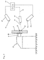
- an object which is mounted to a mounting device 2 by means of a mounting mechanism 3 forms the object under test or to be examined.
- the mounting device 2 may form part of a wheel balancing apparatus or tyre changer.
- the object according to Fig. 1 is preferably a vehicle wheel assembly 1 (in the following named wheel assembly) comprising a rim 4 of the vehicle as well as a tire 5 arranged on the rim 4.
- the rim 4 of the wheel assembly 1 having the tire 5 arranged thereon is mounted to the mounting mechanism 3 of the mounting device 2, which may preferably be a wheel balancing apparatus or a tyre changer.
- the wheel assembly 1 is fixed in a known manner to a shaft 6 which forms part of the mounting mechanism 3.
- the object in the form of the wheel assembly 1 is, thus, fixed to the mounting mechanism 3 of the mounting device 2 (wheel balancing apparatus or a tyre changer) and is rotatably supported about an axis of rotation (wheel axis 7) defined by the shaft 6.
- the shaft 6 coincides with the wheel axis 7 (axis of the wheel assembly 1), and this arrangement ensures that the wheel axis 7 is stationary when the wheel assembly is mounted to the mounting device 2 and can only perform a rotational movement.
- the wheel assembly 1 being in the centered position is mounted in conjunction with a coupling plate 8 which can define a reference position and in particular a reference plane 9 for the wheel assembly 1 in conjunction with the wheel axis 7 or the shaft 6.
- the reference plane 9 is perpendicular to the wheel axis 7 of the wheel assembly 1 and the extension of the shaft 6 and constitutes the plane in which the wheel assembly 1 rotates when the mounting device 2 (wheel balancing apparatus or tyre changer) is operated.
- the shaft 6 forms in the balancing apparatus the measuring shaft and in the tyre changer the shaft on which the wheel assembly 1 is fixed for the tyre changing operation.
- the parameter detection system further comprises at least a first camera 10 and a second camera 11 which are arranged for picking up images from a particular predetermined side or portion of the wheel assembly 1.
- both the first and the second cameras 10 and 11 are directed to the particular side of the wheel assembly 1 which is not facing the coupling plate 8 of the mounting mechanism 3.
- both the first and the second cameras 10 and 11 are basically directed to the measuring shaft 6 or the wheel axis 7.
- Each of a first and second camera 10 and 11 comprises an optical lens (image pickup lens, objective lens) for forming an object image of the object to be examined (such as the wheel assembly 1), as well as an image pickup means (not shown) provided in the form of a semiconductor sensor (CCD sensor or CMOS-sensor) for sensing the object image provided by the optical lens.
- Corresponding output signals are generated and are transmitted to a central control unit 13 (CCU) for further data evaluation. That is, both the first and the second cameras 10 and 11 are connected to the central control unit 13 which has the function of a calculation means.
- the central control unit is adapted to provide a control of each of the first and the second cameras 10 and 11.
- the parameter detection system comprises a mobile unit 14 which is a movable device and can be freely moved around the mounting device 2 and around the wheel assembly 1 arranged thereon. Accordingly, the mobile unit 14 can be freely moved within a predetermined working space related to the object under examination.
- the mobile unit 14 comprises a light emitting means 15 for emitting a light beam 16 into a predetermined direction from the mobile unit 14.
- the mobile unit 14 is connected to the central control unit 13 for the transmission of data and operation commands.
- the transmission of data and operation commands is preferably bidirectional.
- the mobile unit 14 can be connected to the central control unit 13 by means of a connection wire 17 (shown in Fig. 1 as a dashed line) which is a flexible cord and allows free movement of the mobile unit 14 when handled by an operator.
- the mobile unit 14 is not limited to having a wired connection with the central control unit 13, but can also have a wireless connection based on a radio frequency (RF) communication link.
- RF radio frequency
- a wired connection is omissible, and the mobile unit 14 further includes a power supply means which may be provided in the form of a battery or an accumulator.
- the power supply means provides power to all electrical or electronical devices as well as the light emitting means 15 arranged in or at the mobile unit 14.
- the mobile unit 14 may further include an operation button 18 for manual operation by the operator or user of the mobile unit 14 for sending instructions to the central control unit 13 in a wired or wireless manner.
- the parameter detection system of the present invention which can also be described as a non-contact or non-mechanical analytical system, is operated for detecting parameters related to the wheel assembly 1 which is the object to be examined.
- the parameter detection system facilitates picking-up of the necessary parameters related to the wheel assembly 1 so that properties and characteristic parameters of the wheel assembly 1 can be input to the central control unit 13 for further data evaluation.
- the kind of vehicle wheel that is, the kind of rim 4 and tire 5 of the wheel assembly 1 can be determined based on the detected parameters peculiar to the wheel assembly 1 under examination.
- the parameter detection system of the present invention therefore also functions as a parameter input device.
- Both the first and the second cameras 10 and 11 which have the function of a sensing means adapted for sensing a position on the object (wheel assembly 1) to be examined, are basically arranged according to the schematic representation of Fig. 1 .
- the first and the second cameras 10 and 11 are calibrated, that is, are adjusted and aligned to aim at the wheel assembly 1 and specifically to the rim 4 or the tire 5 thereof.
- the pair of cameras (first and second cameras 10 and 11) are properly set and calibrated, it is possible to pick up images of the wheel assembly 1, and specifically of a predetermined portion of interest thereof.
- the pictures picked-up by each of the cameras 10 and 11 are input to the central control unit 13 and can be subject to any predetermined data evaluation such as, for example, a data comparison process or a data matching process to obtain a corresponding detection result.
- the operator can use the mobile unit 14 which is a handheld and freely movable device and which is able to emit a light beam to a direction defined by the user or operator.
- the light emitting means 15 may be a light emitting diode LED with a integrated condenser lens (not shown) for emitting a small and precisely focused light beam.
- the light emitting means 15 is provided in the form of a semiconductor laser, and the light beam 16 is preferably a laser light beam which causes, when the mobile unit 14 is directed to the wheel assembly 1, a well-focused and easily identifiable beam spot 19 (illuminated position) at a predetermined position on the wheel assembly 1 desired or intended by the user or operator when handling the mobile unit 14. If a diffused emitting means 15, i.e. one diffused emitter on an array of diffused emitters in form of LEO, the emitting means 15 is placed closely to the position of interest.
- the user directs the mobile unit 14 including the light emitting means 15 to the wheel assembly 1 and creates the beam spot 19 at the predetermined position on the wheel assembly 1.
- the beam spot 19 on the wheel assembly 1 at any arbitrary position and indicative of the position of interest is picked-up as a corresponding image by both the first and the second cameras 10 and 11, and both images are subject to a predetermined data evaluation in the central control unit 13.
- Based on the signals transmitted to the central control unit 13 and as a result of the data evaluation (which may preferably be a correlated data evaluation and/or calculation) an exact spatial position of the beam spot 19 can be determined.
- a particular beam spot 19 selected or created by the user represents the predetermined position on the wheel assembly 1 of interest
- the user can use or press the operation button 18 on the mobile unit 14 to give an instruction to the central control unit 13 regarding the present beam spot 19.
- the parameter detection system of the present invention When the parameter detection system of the present invention is instructed to define a particular position on the wheel assembly 1 corresponding to the selected beam spot 19, such data are stored in the central control unit 13, the data representing that at least one parameter related to the wheel assembly 1 and measured by the parameter detection system according to the present invention.
- the pair of cameras 10 and 11 When the pair of cameras 10 and 11 is properly calibrated, it is possible to exactly reconstruct the 3D world coordinates of the predetermined position (beam spot 19) on the wheel assembly 1 (created by the light emitting means 15 of the mobile unit 14 and as seen by both cameras 10 and 11) by means of projective transformation. Since the calibration of both cameras 10 and 11, which may constitute a stereo system, is basically a calibration of the relationship between the two camera sensors (semiconductor image pickup means), the predetermined position detected by this arrangement, that is, the position of the beam spot 19 on the wheel assembly 1 is free.
- free means a free and independent movement of the mobile unit 14 within the predetermined working space around the wheel assembly 1 and the projection of a beam spot 19 on any arbitrary position on the wheel assembly 1, provided that the beam spot 19 at the position of interest lies within the image pickup arranged of each of the cameras 10 and 11.
- the parameter detection system according to the present invention therefore, provides the operator with the handheld mobile unit 14 which has preferably a laser light emitter, and the user or operator can use the beam spot 19 on the rim 4 of the wheel assembly 1 to point to the exact position or positions on the rim 4 where the user wants to attach wheel weights for obtaining the necessary wheel balance.
- the stereo system composed of the first and the second cameras 10 and 11 can measure the real-world coordinates (three-dimensional coordinates) of the indicated positions on the wheel assembly 1 and can use the corresponding detection results output by each of the cameras 10 and 11 for specific calculations, which can also be used for determining the properties and parameters related to the wheel assembly 1. That is, the parameter detection system according to the present invention serves for inputting the parameters in question or of interest.
- the operation button 18 serves as a confirmation button which the user should press to confirm that the currently pointed or highlighted position (position of the beam spot 19 on the wheel assembly 1) is the required one, i.e. the predetermined position of interest.
- the parameter detection system is thus adapted to detect parameters related to the wheel assembly 1 (based on the detection of three-dimensional positions) to determine the properties and characteristics of the rim 4 (and of tire 5) of the wheel assembly 1, as well as to determine the predetermined position where a balance weight for balancing the wheel assembly 1 of the vehicle is to be arranged.
- the principles are the same in both cases.
- the detected data and specifically the parameters of interest can be stored in the central control unit 13 and can be displayed on a display means (not shown) connected to the central control unit 13. If the wheel assembly 1 is fixed on the shaft of a tyre changer, the detected parameters can be used to control the movement of the mounting or demounting tool during the tyre changing operation.
- the arrangement of the parameter detection system according to the present invention provides an easy handling of the particular means and devices of the parameter detection system so that even less-qualified personal or any layman can operate the parameter detection system of the present invention and can obtain in an easy manner reliable detection results, provided that before use of the parameter detection system the image pickup means in the form of the first and second cameras 10 and 11 are properly adjusted (calibrated).
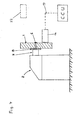
- the parameters detected by the parameter detection system of the present invention can be determined in three-dimensional world coordinates relative to a reference point or the reference plane 9.
- Fig. 2 shows reference plane 9 as an exemplary reference plane which is preferably perpendicular to the wheel axis 7 of the wheel assembly 1 and the measuring shaft 6. This particular reference plane 9 can be used as it is probably adjusted in conjunction with the coupling plate 8 of the mounting mechanism 3.
- the present invention is, however, not limited to the arrangement of the reference plane 9, and any other arbitrary but fixed reference point or reference plane can be used.
- the detection result of the parameter detection system of the present invention has to be interpreted in conjunction with the selected or calibrated reference point or reference plane.
- the present invention is further not limited to the detection of parameters related to a vehicle wheel assembly forming the object of interest, based on the detection of three-dimensional positions. It is possible to perform a corresponding measurement with any arbitrary object mounted at a fixed position and having a more or less irregular surface so that arbitrary positions on the surface of the object can be marked with the beam spot 19 and can be evaluated and, as a final result of the evaluation, be presented as precise parameters related to the object of interest.
- the invention can be used for supporting any manufacturing process, and specifically the manufacturing process of tires and rims of a vehicle wheel assembly or any other product.
- the parameter detection system comprises a mounting device 2 to which a wheel assembly (object of interest; vehicle wheel assembly) 1 is mounted.
- the mounting process of the wheel assembly 1 to the mounting device 2 involves a mounting mechanism 3 which includes a coupling plate 8 to which the wheel assembly 1 is pressed.
- the wheel assembly 1 is fixedly mounted to the mounting mechanism 3 specifically on a shaft 6, and can be rotated in a plane perpendicular to the shaft 6 which is identical to the wheel axis 7 (see Fig. 2 , not shown in Fig. 3 ) of the wheel assembly 1.
- the mounting device 2 is preferably provided in the form of a wheel balancing apparatus for carrying out a wheel balancing process to determine the balancing weight for the wheel assembly 1, as well as the position for applying the balancing weight (not shown) to the wheel assembly 1.
- the mounting device 2 can also be designed as a tyre changer onto its shaft the wheel assembly 1 is fixed for the tyre changing operation.
- the parameter detection system for detecting the necessary parameters related to the wheel assembly 1 as well as the specific position for applying the balancing weight, and for obtaining detailed coordinates of these positions or points of interest, the parameter detection system according to the present invention further comprises a mobile unit 14 which is (similar to the mobile unit 14 of the first embodiment, Figs. 1 and 2 ) freely movable in the space around the wheel assembly 1 mounted to the mounting device 2.
- the mobile unit 14 includes an emitting means (not shown) for emitting in a wireless manner any radiation, which can be sensed and received by corresponding receivers 20.
- Fig. 3 shows at least three receivers 20 which are arranged on holders 21 to be at the position for undisturbed reception of the radiation (signals) transmitted by the mobile unit 14.
- the locations of the holders 21 and the receivers 20 are preferably predetermined positions and the receivers 20 have the function of a sensing means.
- the mobile unit 14 may be adapted to emit an ultrasonic sound, and the receivers 20 are provided as ultrasonic transducers.
- the present invention is not limited to the use of ultrasonic signals transmitted from the mobile unit 14 to the receivers 20, but any radiation such as radio frequency (RF) can be used as long as the receivers 20 are adapted to the kind of radiation and frequency for undisturbed and untroubled reception of the corresponding signals.
- RF radio frequency
- the at least three receivers 20 are connected typically by a wired connection to a central control unit 13 which includes a corresponding program based on a control concept for providing the overall control of the parameter detection system of the present invention according to the second embodiment thereof.
- the detection signals generated by the plurality of receivers 20 are supplied to the central control unit 13 (calculation means).
- the central control unit 13 performs the data evaluation and provides as a final result the parameters related to the wheel assembly 1 measured by the received signals of the receivers 20.
- a confirmation button (not shown in Fig. 3 ) can be operated by the user and the parameter detection system according to the present invention starts operation and measurement of the parameters of interest by transmitting preferably ultrasonic signals from the mobile unit 14 to the plurality of receivers 20. Based on the received signals spatial coordinates of the position of interest are determined and finally the parameters in conjunction with this position of interest can be calculated.
- the central control unit 13 may instruct storage and display of the final results to inform the user or operator accordingly.
- the mobile unit 14 may also have a wireless or wired connection 17 to the central control unit 13 for in a bidirectional manner communicating signals and instructions to and from the mobile unit 14 from and to the central control unit 13.
- the parameter detection system according to the second embodiment of the present invention requires an initial setting (presetting) or calibration, and for obtaining a proper calibration a reference position 22 for disposing the mobile unit 14 is provided.
- This reference position 22 may constitute a rest position as well as a calibration position.
- the parameter detection system according the present invention can be controlled by the central control unit 13 to automatically perform calibration and basical setting of the entire system.
- the basical setting includes the storage of basic parameters related to the wheel assembly 1 (object to be examined) for carrying out a specific data matching operation to determine, for example, the kind of rim or tire.
- the initial position or rest position 22 is shown in Fig. 3 as a dashed block.
- the position of the mobile unit 14 relative to the positions of the plural receivers 20 is defined when specifically the mobile unit 14 is placed at the reference position 22 (initial position or rest position).
- Basic data can then be obtained, and when the mobile unit 14 is moved to any other arbitrary position in space the relative position of the mobile unit 14 to the plural receivers 20 can be determined.
- the detection and determination of the actual arbitrary position of the mobile unit 14 can be carried out provided that the mobile unit 14 is located within the detection range of the parameter detection system of the present invention. This possible detection range is basically defined by the arrangement of the plural receivers 20.
- the detection and determination of the actual arbitrary position of the mobile unit 14 can be carried out continuously or intermittently, that is, every predetermined period of time.
- the at least three receivers (transponder) 20 are placed in known positions relative to the mounting device 2 (for example a wheel balancing apparatus) and the position of the mobile unit 14 in the working position (close to the object to be examined) or in the rest position 22.
- the radiation emitting means in the mobile unit 14 may preferably be an ultrasonic emitter, and the receivers may be ultrasonic transducers.
- the distance of the mobile unit 14 (including the emitter) from each of the plural receivers 20 will be determined by means of a time-of-flight technique, wherein distance is found by the time it takes for the ultrasonic signals (radiation, ultrasonic pulses) to proceed from the mobile unit 14 to each of the plural receivers 20 and multiplying by the speed of the sound.
- synchronisation between the emitter of the mobile unit 14 and each of the at least three receivers 20 is required.
- This can be achieved by means of a dedicated wire, by means of a light emitter-receiver pair, typically by using infrared light (IR), by means of a radio frequency emitter-receiver pair (RF emitter-receiver pair), or in the manner based on the exchange of ultrasonic pulse signals between the emitter of the (handheld) mobile unit 14 and the plurality of receivers 20.
- IR infrared light
- RF emitter-receiver pair radio frequency emitter-receiver pair
- synchronisation between the emitter of the mobile unit 14 and the plural receivers 20 is achieved by a request-response handshake protocol.
- the 3D world coordinates of the mobile unit 14 that is, the (x, y, z) positions in three degrees of freedom, can be determined by means of trilateration.
- a phase-coherence method can be used in theory.
- This principle uses a signal phase difference to determine a position. Based on the use of ultrasonic signals, since sound travelled by means of a sinusoidal waveform is performed, the signal phase angle at a fixed position of the receiver 20 and the mobile unit 14 will always remain constant. As the receivers 20 relatively move away from the emitter of the mobile unit 14 when the mobile unit 14 is moved, the signal phase angle will change because sound waves need to travel further to get to each of the receivers 20. This change in the signal phase angle can be converted into a change in distance from the mobile unit 14 (emitter, transmitter), since the ultrasonic signal wavelength is known.
- RF radio frequency
- the use of the ultrasonic trilateration is immune to electrical and magnetic interference. Electrical and magnetic fields do not affect ultrasonic sound waves, therefore, the environment does not need to be free of electrical cables, monitors, computers, and ferrous metal fixtures.
- tracking of the mobile unit and, thus, of a position where the mobile unit 14 is actually located is not affected by any nearby objects. Ultrasonic sound waves do not change their properties or waveform when other objects are in the vicinity of the tracked mobile unit 14.
- the mobile unit 14 is preferably a light weight unit including the emitter or transmitter and can easily be carried or held by a person (such as an operator).
- the performance of the parameter detection system of the second embodiment can be maintained due to the easy handling and save operation, even when less-qualified staff operates the system.
- the initial position or rest position 22 of the mobile unit which serves for calibration is schematically shown in Fig. 3 at a predetermined location (dashed block).
- the present invention is however not restricted to this arrangement or positioning of the mobile unit 14, but any position can constitute the rest position for the mobile unit 14 for calibration, provided that it completely lies within the general detection range of the system.
- an object to be examined is provided in the form of a wheel assembly 1 (vehicle wheel assembly) which is mounted to a mounting device 2 by means of a mounting mechanism 3.
- the wheel assembly 1 is specifically positioned on a shaft 6 and is urged against a coupling plate 8 forming part of the mounting mechanism 3, by a specific lock means (not shown) to obtain the desired fixed position on the mounting device 2.
- the wheel assembly 1 forming the object to be examined is fixedly mounted in view of its position and can only be rotated around the axis of the wheel assembly 1 (wheel axis 7 which is identical to the extension of the shaft 6).
- the shaft 6 can be the measuring shaft of a balancing apparatus or the shaft of the rotation device of a tyre changer.
- the parameter detection system according to the third embodiment further comprises a mobile unit 14 which is like in the first and second embodiments freely movable within an allowable working space around the mounting device 2 where the wheel assembly 1 of a vehicle is under examination. Specifically, parameters and further properties of the wheel assembly 1 are of interest and are to be detected.
- the wheel assembly 1 consists of a rim 4 and a tire 5. This is not shown in Figs. 4 and 5 , and it is referred to the details shown in Fig. 2 .
- the mobile unit 14 which can be moved freely within the working space around the mounting device 2 has an initial position or a reference position 22 (which may also be a rest position) as shown in Fig. 4 by means of a dashed block.
- the reference position 22 is a predetermined and a known position which serves for calibration and presetting of the position detection process to be performed according to the parameter detection system of the present invention. That is, after calibration of the position of the mobile unit 14 being placed to this end at the reference position 22, the mobile unit 14 is moved to any position on or at the object to be examined, preferably in the form of the wheel assembly 1, and the detected position of the mobile unit 14 placed at the wheel assembly 1 provides the basis for the detection of this particular position on or at the wheel assembly 1.
- At least one parameter of the wheel assembly 1 (parameters related to size, shape and further properties of the wheel assembly 1) can be derived there from.
- This performance or function corresponds to the performance or function of the parameter detection system of the first and second embodiments of the present invention.
- the mobile unit 14 is connected to a central control unit 13 which has the function of a calculation means and serves for an overall control of the parameter detection system of the present invention, including the storage and performance of corresponding control and data evaluation software, handling and storing data, receiving and transmitting data and instructions to and from the mobile unit 14.
- connection between the mobile unit 14 and the central control unit 13 may be a flexible wire such as, for example, a multi-conductor wire, or may be provided in the form of a wireless data communication link based, for example, on a radio frequency (RF) data communication link.
- RF radio frequency
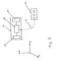
- Fig. 5 there are shown further details of the mobile unit 14 connected in a wired or wireless manner to the central control unit 13.
- the mobile unit 14 is a handheld device to be manually positioned by an operator.
- the mobile unit 14 includes at least a first sensor means 23 and at least a second sensor means 24 which are arranged in the mobile unit 14 and are connected to a controller 25 for driving the at least first and second sensor means 23 and 24 and for inputting detection signals of these sensor means 23 and 24.
- the controller 25 of the mobile unit 14 is further adapted for respectively transmitting in a wired or wireless manner by means of a wire 17 or a wireless data communication link (including transmitters and receivers) the detection signals for further detailed data evaluation to the central control unit 13.
- the at least first and second sensor means 23 and 24 are arranged to detect any movement of the mobile unit 14 such as a linear movement or any rotational movement or any combination thereof in all directions x, y and z (three axes), so that the position and orientation of the mobile unit 14 can be determined according to the 6 degrees of freedom. That is, at least first and second sensor means 23 and 24 are provided for sensing a linear and an angular orientation of the mobile unit 14 which is freely movable in all degrees of freedom in the predetermined working space around the object to be examined.
- the at least first and second sensor means 23 and 24 are preferably provided in the form of accelerometers to measure the linear and angular orientation rates, such as movement of the mobile unit 14 in a linear or curved manner.
- accelerometers it is necessary in order to measure the acceleration along the three axes of the mobile unit 14 (object to be tracked) simultaneously, to have three accelerometer movements, each arranged perpendicular to one of the axes.
- Integrated circuit technology has advanced to the point where these sensor means are small enough to be used in position tracking, i.e. in detection of the actual position of the mobile unit 14 including such sensor means.
- Sensors are available as of off-the-shelf parts for measuring in the three axes configured as a single package, usually based on MEMS technology (micro-electro-mechanical system).
- the output signals of a linear accelerometer need to be integrated twice to derive an actual position. Integration causes the actual positions and orientations to be sensitive to drift, and it is necessary to re-calibrate the parameter detection system periodically. This can be done at any time when the mobile unit 14 is placed at the reference position 22 as shown in Fig. 4 .
- the reference position 22 may form an initial position (or rest position) relative to which the position during an actual movement of the mobile unit 14 is detected or measured.
- the reference position 22 therefore allows presetting and calibration of the at least first and second sensors means 23 and 24.
- the parameter detection system (3-D tracking system) according to the third embodiment of the present invention provides the following advantages.
- the parameter detection system of the present invention detects parameters related to the wheel assembly 1 which is the object to be examined, and when the parameters are detected and are thereby input to the system, the further operation of, for example, a wheel balancing apparatus or of a tyre changer can be controlled on the basis of the detected parameters.
- These parameters may relate to the shape, size and further properties of a rim or a tire of the wheel assembly 1.
- the parameter detection system of the present invention also serves as a data input means which can be operated in a semi-automatic manner.
- the parameter detection system according to the third embodiment needs no emitting means for emitting any signals, such as ultrasonic signals, and no corresponding receivers.
- the lack of an artificial radiation source means that the inertial tracking mode does not suffer from any signal (noise) or metallic object interference or shadowing.
- the mobile unit 14 can be moved around without limitation (within the allowable detection range), and when transmitting of detected data (tracking data) can be carried out in a wireless manner, a communication cable (connection wire 17) can be omitted.
- the user handling the mobile unit 14 is free to move the mobile unit 14 around in the real world with no restrictions.
- the use of advanced micro-machine inertial sensors as the at least first and second sensor means 23 and 24 and application specific integration circuits can further minimize dimensions (size), costs and weight of the mobile unit 14.
- Application of the parameter detection system according to the third embodiment can be used in a large working volume or workspace since it does not need any emitter for emitting any radiation to perform the tracking of the movement (position) of the mobile unit 14, and no hardware or cabling is required when a wireless data communication link between the mobile unit 14 and the central control unit 13 is preferred.
- the parameter detection system as described above involves low latency, as the position detection based on inertial navigation by means of accelerators is able to derive positional and orientation changes instantaneously by performing integration and double integration directly on the output signals of the linear accelerometers, thereby performing an immediate reaction and a reliable monitoring of the actual position of the mobile unit 14.
- the position can be detected reliably so that the position at the wheel assembly 1 can easily and reliably be detected within a short period of time.
- the system provides an easy handling and operation so that even less-qualified personal can obtain reliable detection results very quickly.
- the fourth embodiment of the present invention referring to a parameter detection system involves at least two of the parameter detection systems described previously in the form of a first, a second and a third embodiment thereof.
- this may increase costs and technical effort, but provides a further increase in precision and flexibility.
- the precision can be increased, and also the working range (allowable space) for operating the parameter detection system can be increased.
- the parameter detection system according to the present invention is applied not only to a wheel balancing apparatus or tire changer and a wheel assembly mounted thereon, which requires a certain working space, but is applied to the general detection of regular or irregular shapes of any product the dimensions of which are to be monitored and input for data evaluation or test.
- the parameter detection system according to the fourth embodiment involves the detection systems as described in the second and third embodiments. That is, the detection systems according to the second and third embodiments are structured as described above and exhibit the corresponding function.
- the detection system according to the second embodiment (TOF, time-of-flight trilateration), which involves the mobile unit 14 emitting in a wireless manner any variation, as well as at least three receivers 20 for receiving the emitted signals, and the detection system according to the fourth embodiment having the mobile unit 14 to be freely moved around the object to be examined and including the first and second sensor means to detect any movement of the mobile unit 14 can both be connected to one and the same central control unit 13 combining the structural and functional properties (software and hardware) of the individual central control units 13 of the second and third embodiments.
- This configuration allows that based on the connection of both parameter detection systems to the same central control unit 13 that a common data handling, such as data evaluation and data storage, can be performed within the same circuit arrangement.
- each of the parameter detection systems according to the second and third embodiments are provided with their own central control unit 13, and both central control units 13 are connected with an external host computer or any other external system suitable for collecting data detected by the parameter detection systems involved, carrying out a corresponding data evaluation, as well as a control of each of the parameter detection systems.
- the combined parameter detection system operates one of the detection systems to provide a first measurement or a preliminary measurement to at least roughly define the position of the mobile unit 14. Based on the rough preliminary detected position (position in space, three dimensions) during the movement of the mobile unit 14 by the user from (for example) a rest or initial position to a position close to the object to be examined, the corresponding rough position information will be subject to a subsequent update, fine-tuning or in general a correction on the basis of the further detection process and corresponding detection result of the respective other parameter detection system to obtain an increased precision or accuracy in comparison to only one detection by any of the parameter detection systems.
- the first detection process can be carried out by any parameter detection system of the second and third embodiments, and the subsequent detection process can be carried out by the respective other of the parameter detection systems.
- a resulting subsequent or continuous data evaluation will provide in combination or interaction a specific improved result, thus increasing accuracy and simultaneously reducing detection errors.
- the first detection process can preferably be carried out by the parameter detection system according to the third embodiment performing a 3-D-tracking with evaluating the output signals of the at least first and second sensor means 23 and 34 arranged in the mobile unit 14.
- a preliminary data evaluation can be carried out by the controller 25 which is also arranged in the mobile unit 14, and the controller 25 is further adapted for transmitting in a wireless manner or by means of a wire 17 on the basis of an established data communication link the detection signals for further detailed data evaluation to the central control unit 13. This constitutes a first detection process resulting in a first detection signal.
- the parameter detection system according to the third embodiment is considered to form the first sensing unit of the fourth embodiment and as mentioned in the claims.
- the first detection process (first measurement) is carried out on the basis of the parameter detection system according to the third embodiment (first sensing unit), this parameter detection system being in general continuously operated during the movement of the mobile unit 14.
- the detection result which may be considered to be a preliminary detection result obtained by the operation of the parameter detection system according to the third embodiment under the first detection process can be stored and according to a specific data evaluation a current position of the mobile unit 14 was reached can be defined as the preliminary information in the form of the first detection signal.
- a second measurement to constitute a second detection process can be carried out by the parameter detection system according to the second embodiment involving time-of-flight trilateration, and the detection result in the form of a second detection signal can also be stored and can be subject to a further data evaluation.
- the parameter detection system according to the second embodiment constitutes in the fourth embodiment a second sensing unit. In the claims, it is also referred the second sensing unit.
- both parameter detection systems are connected to the same central control unit 13 forming a central controller of the data evaluation and of the control of each of the parameter detection systems, or since a central control unit 13 individually assigned to each of the parameter detection systems is connected to a central computer for combined data evaluation, the detection results of both parameter detection systems (first and second sensing units) can be treated according to a predetermined software, according to a manual setting of the conditions for data evaluation and depending upon the detection situation resulting from a correlation of the detection results obtained under the first and second detection processes.
- the first and second detection process are carried out.
- the expressions "first" and “second” distinguish between different and basically independent detection processes.
- the reference to a first and a second detection process does not exclude that both detection processes can be carried out in parallel, i.e. at the same time.
- the first and second detection process can be carried out according to a predetermined sequence or in an automatic manner (for example under a time control) or on a manual request to obtain a specific detection result under the first and the second detection process, respectively.
- the central control unit 13 is adapted for performing the complete data evaluation as well as the control the operation of the detection system (first and second sensing units in view of their timing of operation. That is, central control unit 13 may control the start of the operation of both detection systems individually and independently, the duration of the operation and the stopping thereof.
- the detection of the position of the mobile unit 14 can independently be carried out by the two different detection systems according to the second and third embodiments of the present invention.
- Two separate detection results being independent form each other can be obtained and can be subject to any data evaluation, such as the data matching, a comparison of data of the two measurements (first and second detection processes) or with pre-stored or previously stored values, a correlation of the detection results, to obtain a true and accurate position of the mobile unit 14.
- the parameter detection system according to the fourth embodiment operates as follows.
- the parameter detection system according to the third embodiment (the first sensing unit) for carrying out the first detection process can be operated continuously or can mainly be operated for detecting the current position of the mobile unit 14 during movement thereof.
- the operation of the parameter detection system for carrying out the first detection process is described in detail above in conjunction with the third embodiment.
- the parameter detection system according to the third embodiment and including first and second sensor means 23 and 24 in the mobile unit 14 can be continuously operated as this parameter detection system can be operated with low power consumption, and the system does not suffer of a restricted work space volume and a direct line-of-sight.
- the parameter detection system according to the third embodiment can be operated without such limitations, and the output signals of the respective first and second sensor means 23 and 24 can be obtained continuously or intermittently with longer periods of being switched on for detecting the current position of the mobile unit 14 and outputting the first detection signal indicative of the desired position.
- the parameter detection system in general performs a tracking of the position of the mobile unit 14 on the basis of the first and second sensor means 23 and 24 (provided in the form of acceleration sensors) a relative measurement is performed for determining the position and the orientation of the mobile unit 14 according to the six degrees of freedom. A continuous operation is necessary to keep track of the actual or current position and orientation of the mobile unit 14 when moved.
- the position and orientation of the mobile unit 14 detected by the parameter detection system according to the third embodiment in the present fourth embodiment constitutes a kind of first or preliminary information about the operation parameters of the mobile unit 14, but any tracking of a position and orientation of the mobile unit 14 based on acceleration sensors such as the first and second sensor means 23 and 24 tends to accumulate errors over the time of operation.
- the mobile unit 14 must periodically be returned to a known position such as a home position (rest position) or any other known reference positions 22 as shown in figure 4 .
- the reference position 22 may also constitute an initial position relative to which the position and the orientation of the mobile unit during an actual movement is detected or measured by the parameter detection system according to the third embodiment.
- a periodical return of the mobile unit 14 to the home position or reference position 22 allows to again implement a predetermined position as a precise basic position or to correct any offset (the continuously accumulated error).
- a periodical measurement under the second detection process involving the parameter detection system according to the second embodiment may be carried out and the corresponding detection result may be used for automatically, or on request, provide the necessary resetting or offset correction of the detection result obtained under the first detection process involving the parameter detection system according to the third embodiment.
- the periodical offset correction may be performed according to a predetermined and manually adjustable time condition, that is, points of time at which the offset correction is to be carried out, or may be provided in conjunction with a predetermined space around the object 1 to be examined (the mounting device 2 holding the object 1, see Figures 1 , 3 and 4 ), that is, when the preliminarily detected position (obtained under the first detection process) has been evaluated and it is determined that the mobile unit 14 is actually located within a predetermined space around the object 1 to be examined.
- a predetermined and manually adjustable time condition that is, points of time at which the offset correction is to be carried out
- an offset correction can be carried out, based on the measurement performed under the second detection process and based on the detection result (second detection signal) of the second sensing unit, so that the detection result obtained under the first detection process is modified or in general influenced by the frequently obtained detection result under the second detection process under predetermined conditions (such as for example time conditions or geometrical conditions).
- the predetermined conditions may be for example the time duration of a movement of the mobile unit 14 longer than a certain period of time, the entrance into a predetermined space around the object to be examined or a manual operation by the user which may have the highest priority and when operated provides an override.
- the corresponding control is carried out by the central control unit 13.
- the first and second sensing units are therefore under control of the central control unit 13 which also has the function of a calculation unit.
- the predetermined conditions in the form of a time-based conditions may form every now and then (adjustable) a trigger to activate the parameter detection system according to the second embodiment to perform the second detection process to obtain fresh and updated measurement or detection results (second detection signal), that is, to determine a "fresh" absolute actual position to correct and re-feed the 3-D-tracking with acceleration.
- the mobile unit 14 can be provided with a proximity sensor (not shown) for detecting the presence of the mobile unit 14 close to any object under test, such as the object 1 as shown in Figures 3 and 4 .
- the detection result of the proximity sensor can be used to automatically activate the fine-tuning concept (offset correction) of the detection results obtained under the first detection process by the detection result obtained under the second detection process when a position of the mobile unit 14 close to the object is reached. This basically corresponds to the predetermined space defined around the object to be examined.
- the second measurement under the second detection process is provided temporarily or on request or under fulfillment of the predetermined conditions, and the offset correction can be performed to obtain an accurate position of the mobile unit 14 only under the specified predetermined conditions.
- a continuous data evaluation is provided in conjunction with the first detection process and the parameter detection system according to the third embodiment (first sensing unit) and on the other hand a temporary measurement and data evaluation is provided under the second detection process in conjunction with the parameter detection system according to the second embodiment (second sensing unit), and the continuous data evaluation in combination with an intermittent or temporal data evaluation will provide a combination or interaction of the results, that is, a predetermined influence of a particular measurement on the other measurement, thereby increasing accuracy of the detection result and considerably reducing detection errors.
- the parameter detection system according to the fourth embodiment thus, provides a predetermined interaction between both measurement systems and detection results, as well as a predetermined interaction of the detection results to obtain after the data evaluation a highly accurate detection result.
- the combination of, for example, the parameter detection system according to the first and third embodiments exhibits an increased working space since the working space of the parameter detection system of the third embodiment is only limited by the wireless transmission capability of data between the mobile unit 14 and the central control unit 13 when a wireless data communication link is preferred.
- the parameter detection system involves defining (according to the second and third embodiments) that the position to be detected is relative to, for example, a front end of the mobile unit 14 which is positioned as close as possible to the position of interest on or at the wheel assembly 1.
Landscapes
- Physics & Mathematics (AREA)
- General Physics & Mathematics (AREA)
- Length Measuring Devices By Optical Means (AREA)
- Arrangements For Transmission Of Measured Signals (AREA)
- Length Measuring Devices With Unspecified Measuring Means (AREA)
Priority Applications (1)
| Application Number | Priority Date | Filing Date | Title |
|---|---|---|---|
| EP09005767A EP2112468A1 (de) | 2008-04-24 | 2009-04-24 | Parametererfassungssystem und Steuerungsverfahren |
Applications Claiming Priority (2)
| Application Number | Priority Date | Filing Date | Title |
|---|---|---|---|
| EP08007932A EP2112465A1 (de) | 2008-04-24 | 2008-04-24 | Parametererkennungssystem für Räder |
| EP09005767A EP2112468A1 (de) | 2008-04-24 | 2009-04-24 | Parametererfassungssystem und Steuerungsverfahren |
Publications (1)
| Publication Number | Publication Date |
|---|---|
| EP2112468A1 true EP2112468A1 (de) | 2009-10-28 |
Family
ID=39564238
Family Applications (2)
| Application Number | Title | Priority Date | Filing Date |
|---|---|---|---|
| EP08007932A Withdrawn EP2112465A1 (de) | 2008-04-24 | 2008-04-24 | Parametererkennungssystem für Räder |
| EP09005767A Withdrawn EP2112468A1 (de) | 2008-04-24 | 2009-04-24 | Parametererfassungssystem und Steuerungsverfahren |
Family Applications Before (1)
| Application Number | Title | Priority Date | Filing Date |
|---|---|---|---|
| EP08007932A Withdrawn EP2112465A1 (de) | 2008-04-24 | 2008-04-24 | Parametererkennungssystem für Räder |
Country Status (3)
| Country | Link |
|---|---|
| US (1) | US8169604B2 (de) |
| EP (2) | EP2112465A1 (de) |
| CN (1) | CN101566528A (de) |
Cited By (1)
| Publication number | Priority date | Publication date | Assignee | Title |
|---|---|---|---|---|
| CN109643871A (zh) * | 2016-08-24 | 2019-04-16 | 凯萨系统股份有限公司 | 具有集成的无接触通信单元的充电端口 |
Families Citing this family (29)
| Publication number | Priority date | Publication date | Assignee | Title |
|---|---|---|---|---|
| IT1397079B1 (it) * | 2009-11-23 | 2012-12-28 | Alfautomazione Spa | Metodo ed apparato per il controllo di pneumatici |
| EP2517189B1 (de) | 2009-12-22 | 2014-03-19 | Leddartech Inc. | Aktives 3d-überwachungssystem für verkehrsdetektion |
| CN102620943B (zh) * | 2011-01-30 | 2015-06-03 | 国际商业机器公司 | 在车轮检测中调整卡尔曼滤波器的参数的方法及装置 |
| US8908159B2 (en) | 2011-05-11 | 2014-12-09 | Leddartech Inc. | Multiple-field-of-view scannerless optical rangefinder in high ambient background light |
| WO2012172526A1 (en) | 2011-06-17 | 2012-12-20 | Leddartech Inc. | System and method for traffic side detection and characterization |
| WO2013003739A2 (en) * | 2011-06-30 | 2013-01-03 | Hennessy Industries, Inc. | Sonar method and apparatus for determining material interfaces in wheel servicing equipment |
| ITMI20112253A1 (it) * | 2011-12-13 | 2013-06-14 | Pirelli | Metodo per controllare la deposizione di semilavorati elementari in un processo di confezione di pneumatici per ruote di veicoli |
| EP2820632B8 (de) | 2012-03-02 | 2017-07-26 | Leddartech Inc. | System und verfahren zur mehrzweck-verkehrserkennung und -charakterisierung |
| WO2014048831A1 (en) * | 2012-09-27 | 2014-04-03 | Snap-On Equipment Srl A Unico Socio | Method and system for inspection, maintenance or repair of a vehicle or of a part of a vehicle |
| EP3060879B1 (de) * | 2013-10-22 | 2021-09-22 | Arora, Pooja | Optische vorrichtung und verfahren zur radausrichtung |
| JP6938371B2 (ja) | 2014-09-09 | 2021-09-22 | レッダーテック インコーポレイテッド | 検出ゾーンの離散化 |
| NL2014195B1 (en) * | 2015-01-27 | 2017-01-11 | Vmi Holland Bv | Validation tool and method for validating optical equipment. |
| JP7353757B2 (ja) * | 2015-07-13 | 2023-10-02 | レニショウ パブリック リミテッド カンパニー | アーチファクトを測定するための方法 |
| CN105136030A (zh) * | 2015-08-24 | 2015-12-09 | 苏州市博得立电源科技有限公司 | 一种自动检测系统 |
| US10429272B2 (en) | 2015-09-30 | 2019-10-01 | Caterpillar Inc. | Command-driven automatic and semi-automatic mobile wear detection |
| WO2017103809A1 (en) * | 2015-12-16 | 2017-06-22 | Pirelli Tyre S.P.A. | Apparatus and method for the analysis of tyres |
| EP3397934B1 (de) * | 2015-12-28 | 2020-02-12 | Pirelli Tyre S.p.A. | Verfahren zur einstellung eines reifenkontrollevorrichtungs, einstellvorrichtung zur durchführung des verfahrens |
| US10794789B2 (en) * | 2016-02-09 | 2020-10-06 | Carlo Buzzi | Method and machine for balancing a vehicle wheel |
| AU2017294796B2 (en) | 2016-07-15 | 2019-05-30 | Fastbrick Ip Pty Ltd | Brick/block laying machine incorporated in a vehicle |
| AU2017294795B2 (en) | 2016-07-15 | 2019-06-13 | Fastbrick Ip Pty Ltd | Boom for material transport |
| US10302532B2 (en) * | 2016-10-03 | 2019-05-28 | Akron Special Machinery, Inc. | Test wheel for use in a tire analysis machine |
| WO2018229805A1 (en) | 2017-06-12 | 2018-12-20 | Pirelli Tyre S.P.A. | Method for checking tyres |
| EP3649616A4 (de) | 2017-07-05 | 2021-04-07 | Fastbrick IP Pty Ltd | Positions- und orientierungsverfolger in echtzeit |
| CN107561092A (zh) * | 2017-07-26 | 2018-01-09 | 天津大学 | 一种钢材表面质量检测方法 |
| CN111226090B (zh) | 2017-08-17 | 2023-05-23 | 快砖知识产权私人有限公司 | 具有改进的横滚角测量的激光跟踪器 |
| CN111246976B (zh) | 2017-08-17 | 2024-03-15 | 快砖知识产权私人有限公司 | 交互系统配置 |
| WO2019071313A1 (en) | 2017-10-11 | 2019-04-18 | Fastbrick Ip Pty Ltd | MACHINE FOR CARRYING OBJECTS AND CARROUSEL WITH SEVERAL COMPARTMENTS FOR USE WITH THE SAME |
| DE102017219407A1 (de) * | 2017-10-27 | 2019-05-02 | Robert Bosch Gmbh | Erfassungsvorrichtung |
| CN116100227B (zh) * | 2023-01-04 | 2023-09-29 | 武汉成华汽车饰件有限公司 | 一种汽车钢轮毂动平衡工艺及焊接设备 |
Citations (4)
| Publication number | Priority date | Publication date | Assignee | Title |
|---|---|---|---|---|
| US6584378B1 (en) | 1999-10-29 | 2003-06-24 | Abb Flexible Automation | Device and a method for determining coordinates and orientation |
| US20060265177A1 (en) | 2005-05-18 | 2006-11-23 | Steinbichler Optotechnik Gmbh | Method for determining the 3D coordinates of the surface of an object |
| WO2007030026A1 (en) | 2005-09-09 | 2007-03-15 | Industrial Research Limited | A 3d scene scanner and a position and orientation system |
| US7269997B2 (en) | 2004-06-03 | 2007-09-18 | Snap-On Incorporated | Non-contact method and system for tire analysis |
Family Cites Families (12)
| Publication number | Priority date | Publication date | Assignee | Title |
|---|---|---|---|---|
| FI74556C (fi) * | 1986-04-11 | 1988-02-08 | Valtion Teknillinen | Foerfarande foer tredimensionell oevervakning av ett maolutrymme. |
| US4957369A (en) * | 1989-01-23 | 1990-09-18 | California Institute Of Technology | Apparatus for measuring three-dimensional surface geometries |
| CA2253085A1 (en) * | 1998-11-06 | 2000-05-06 | Industrial Metrics Inc. | Methods and system for measuring three dimensional spatial coordinates and for external camera calibration necessary for that measurement |
| GB9904653D0 (en) * | 1999-03-02 | 1999-04-21 | Spx United Kingdom Limited | Vehicle poisoning |
| DE19921650C2 (de) * | 1999-05-10 | 2001-09-20 | Continental Ag | Vorrichtung und Verfahren zur Demonstration und/oder zur Ermittlung der Bewegung von mit farblichen Markierungen versehenen Profilelementen eines Reifens mit profilierter Lauffläche |
| FI113293B (fi) * | 2001-04-19 | 2004-03-31 | Mapvision Oy | Menetelmä pisteen osoittamiseksi mittausavaruudessa |
| JP2003240521A (ja) * | 2002-02-21 | 2003-08-27 | Bridgestone Corp | 被検体の外観・形状検査方法とその装置、及び、被検体の外観・形状検出装置 |
| EP1398610B1 (de) * | 2002-09-13 | 2005-05-25 | Snap-on Equipment Srl a unico socio. | Verfahren und Vorrichtung zur Bestimmung der geometrischen Daten eines auf einer Welle drehbar montierten Kraftfahrzeugrades |
| EP1512953B1 (de) * | 2003-09-04 | 2008-12-10 | Snap-on Equipment Srl a unico socio. | Verfahren und Vorrichtung zum optischen Abtasten eines Fahrzeugrades |
| ATE303587T1 (de) * | 2003-09-04 | 2005-09-15 | Snap On Equip Srl Unico Socio | Verfahren zur abstimmung eines fahrzeugrades |
| US7454841B2 (en) * | 2005-11-01 | 2008-11-25 | Hunter Engineering Company | Method and apparatus for wheel alignment system target projection and illumination |
| DE102006014663A1 (de) | 2006-03-28 | 2007-10-04 | Att Automotive Testing Technologies Gmbh | Verfahren und Vorrichtung zum Auswuchten von Rädern |
-
2008
- 2008-04-24 EP EP08007932A patent/EP2112465A1/de not_active Withdrawn
-
2009
- 2009-03-11 US US12/402,069 patent/US8169604B2/en not_active Expired - Fee Related
- 2009-03-24 CN CNA2009101268793A patent/CN101566528A/zh active Pending
- 2009-04-24 EP EP09005767A patent/EP2112468A1/de not_active Withdrawn
Patent Citations (4)
| Publication number | Priority date | Publication date | Assignee | Title |
|---|---|---|---|---|
| US6584378B1 (en) | 1999-10-29 | 2003-06-24 | Abb Flexible Automation | Device and a method for determining coordinates and orientation |
| US7269997B2 (en) | 2004-06-03 | 2007-09-18 | Snap-On Incorporated | Non-contact method and system for tire analysis |
| US20060265177A1 (en) | 2005-05-18 | 2006-11-23 | Steinbichler Optotechnik Gmbh | Method for determining the 3D coordinates of the surface of an object |
| WO2007030026A1 (en) | 2005-09-09 | 2007-03-15 | Industrial Research Limited | A 3d scene scanner and a position and orientation system |
Cited By (2)
| Publication number | Priority date | Publication date | Assignee | Title |
|---|---|---|---|---|
| CN109643871A (zh) * | 2016-08-24 | 2019-04-16 | 凯萨系统股份有限公司 | 具有集成的无接触通信单元的充电端口 |
| US11427097B2 (en) | 2016-08-24 | 2022-08-30 | Molex, Llc | Charging ports with integrated contactless communication units |
Also Published As
| Publication number | Publication date |
|---|---|
| US20090267784A1 (en) | 2009-10-29 |
| US8169604B2 (en) | 2012-05-01 |
| CN101566528A (zh) | 2009-10-28 |
| EP2112465A1 (de) | 2009-10-28 |
Similar Documents
| Publication | Publication Date | Title |
|---|---|---|
| EP2112468A1 (de) | Parametererfassungssystem und Steuerungsverfahren | |
| US8352212B2 (en) | Manipulable aid for dimensional metrology | |
| US7230689B2 (en) | Multi-dimensional measuring system | |
| US9739595B2 (en) | Multi-dimensional measuring system with measuring instrument having 360° angular working range | |
| US8639471B2 (en) | Wireless position sensing in three dimensions using ultrasound | |
| US20150346319A1 (en) | Method and Device for Determining the Position Coordinates of a Target Object | |
| US8199316B2 (en) | Device and method for tracking the movement of a tool of a handling unit | |
| CA2541635A1 (en) | Hybrid sensing apparatus for adaptive robotic processes | |
| WO2003019231A1 (en) | Six dimensional laser tracking system and method | |
| US8848052B2 (en) | Processing method using an electric tool | |
| JP7145851B2 (ja) | 作業システム | |
| CN110850430B (zh) | 激光扫描系统 | |
| US20210190483A1 (en) | Optical sensor with overview camera | |
| KR100616774B1 (ko) | 무선통신을 이용한 이동체의 위치인식시스템 및위치인식방법 | |
| US20130162971A1 (en) | Optical system | |
| KR101921113B1 (ko) | 탐지용 하이브리드 가시광 rfid 태그 및 이에 사용되는 로봇시스템 | |
| US8717579B2 (en) | Distance measuring device using a method of spanning separately targeted endpoints | |
| CN111336915B (zh) | 在工业对象测量期间粗略定位可移动协作目标的系统 | |
| EP3360652B1 (de) | Erkennung des eingriffs eines roboters mit einem objekt | |
| WO2011084136A2 (en) | Method and device for measuring the speed of a movable member relative a fixed member | |
| EP4354079A1 (de) | Positionsmessvorrichtung und positionsmessverfahren | |
| KR101194073B1 (ko) | Igps를 이용한 비젼 트래킹 시스템 및 방법 | |
| CN113749770A (zh) | 医疗设备定位系统 | |
| CN117642598A (zh) | 车辆维修装置和用于执行车辆维修的方法 |
Legal Events
| Date | Code | Title | Description |
|---|---|---|---|
| PUAI | Public reference made under article 153(3) epc to a published international application that has entered the european phase |
Free format text: ORIGINAL CODE: 0009012 |
|
| AK | Designated contracting states |
Kind code of ref document: A1 Designated state(s): AT BE BG CH CY CZ DE DK EE ES FI FR GB GR HR HU IE IS IT LI LT LU LV MC MK MT NL NO PL PT RO SE SI SK TR |
|
| 17P | Request for examination filed |
Effective date: 20100428 |
|
| 17Q | First examination report despatched |
Effective date: 20100525 |
|
| STAA | Information on the status of an ep patent application or granted ep patent |
Free format text: STATUS: THE APPLICATION IS DEEMED TO BE WITHDRAWN |
|
| 18D | Application deemed to be withdrawn |
Effective date: 20151103 |