EP2112121A1 - Vorrichtung zum Handhaben von Behältern - Google Patents
Vorrichtung zum Handhaben von Behältern Download PDFInfo
- Publication number
- EP2112121A1 EP2112121A1 EP09003119A EP09003119A EP2112121A1 EP 2112121 A1 EP2112121 A1 EP 2112121A1 EP 09003119 A EP09003119 A EP 09003119A EP 09003119 A EP09003119 A EP 09003119A EP 2112121 A1 EP2112121 A1 EP 2112121A1
- Authority
- EP
- European Patent Office
- Prior art keywords
- filling
- flushing
- containers
- rinsing
- filling device
- Prior art date
- Legal status (The legal status is an assumption and is not a legal conclusion. Google has not performed a legal analysis and makes no representation as to the accuracy of the status listed.)
- Granted
Links
Images

Classifications
-
- B—PERFORMING OPERATIONS; TRANSPORTING
- B67—OPENING, CLOSING OR CLEANING BOTTLES, JARS OR SIMILAR CONTAINERS; LIQUID HANDLING
- B67C—CLEANING, FILLING WITH LIQUIDS OR SEMILIQUIDS, OR EMPTYING, OF BOTTLES, JARS, CANS, CASKS, BARRELS, OR SIMILAR CONTAINERS, NOT OTHERWISE PROVIDED FOR; FUNNELS
- B67C3/00—Bottling liquids or semiliquids; Filling jars or cans with liquids or semiliquids using bottling or like apparatus; Filling casks or barrels with liquids or semiliquids
- B67C3/02—Bottling liquids or semiliquids; Filling jars or cans with liquids or semiliquids using bottling or like apparatus
- B67C3/06—Bottling liquids or semiliquids; Filling jars or cans with liquids or semiliquids using bottling or like apparatus using counterpressure, i.e. filling while the container is under pressure
- B67C3/10—Bottling liquids or semiliquids; Filling jars or cans with liquids or semiliquids using bottling or like apparatus using counterpressure, i.e. filling while the container is under pressure preliminary filling with inert gases, e.g. carbon dioxide
-
- B—PERFORMING OPERATIONS; TRANSPORTING
- B67—OPENING, CLOSING OR CLEANING BOTTLES, JARS OR SIMILAR CONTAINERS; LIQUID HANDLING
- B67C—CLEANING, FILLING WITH LIQUIDS OR SEMILIQUIDS, OR EMPTYING, OF BOTTLES, JARS, CANS, CASKS, BARRELS, OR SIMILAR CONTAINERS, NOT OTHERWISE PROVIDED FOR; FUNNELS
- B67C3/00—Bottling liquids or semiliquids; Filling jars or cans with liquids or semiliquids using bottling or like apparatus; Filling casks or barrels with liquids or semiliquids
- B67C3/02—Bottling liquids or semiliquids; Filling jars or cans with liquids or semiliquids using bottling or like apparatus
-
- B—PERFORMING OPERATIONS; TRANSPORTING
- B67—OPENING, CLOSING OR CLEANING BOTTLES, JARS OR SIMILAR CONTAINERS; LIQUID HANDLING
- B67C—CLEANING, FILLING WITH LIQUIDS OR SEMILIQUIDS, OR EMPTYING, OF BOTTLES, JARS, CANS, CASKS, BARRELS, OR SIMILAR CONTAINERS, NOT OTHERWISE PROVIDED FOR; FUNNELS
- B67C7/00—Concurrent cleaning, filling, and closing of bottles; Processes or devices for at least two of these operations
Definitions
- the invention relates to a device for handling containers of the type explained in the preamble of claim 1.
- Such a device is known from DE 10 2005 014 076 A1 known.
- the known device is used for internal flushing of containers immediately before filling and serves primarily the purpose of displacing the air from the containers to be filled prior to filling of oxygen-sensitive drinks, so that the beverage can be filled substantially free of oxygen.
- the interior rinsing is carried out with gas and / or steam, in particular CO 2 is used.
- the inner flushing is done directly in the filling, which offers the greatest temporal proximity to the filling.
- the filling head of the filling device is modified, so that the purge gas can be injected directly in front of the beverage by means integrated in the filling head.
- the invention has for its object to provide a device for handling containers, with the economic and easy indoor flushing can be made.
- the filling device Due to the spatial decoupling of filling and internal flushing the filling device must be designed only to the time necessary for filling, which saves investment costs and parking space. In addition, it is rinsed dry, using annoying product residues are not to be feared. In addition, the CO 2 consumption can be optimized and minimized.
- the arrangement of the device for flushing directly before the inlet of the filling the time between the inner rinsing and the placement of the filling is reduced to a minimum, so that the risk that atmospheric oxygen gets back into the container is greatly reduced.
- the device for internal rinsing is located on an inlet star of the filling device, which then passes the rinsed containers directly to the filling device, wherein preferably a plurality of internal rinsing devices are provided per filling device.
- the flushing head can also perform a pivoting movement in addition to a lifting and lowering movement, so that it can be pivoted over the container opening and swung away after flushing in order to make room for the filling head.
- This movement is preferably effected by a single drive means, for example a lift-swing cylinder.
- the flushing is optimized when the flushing head has an obliquely inclined to the center line of the container Ein Albanyö réelle, as for example in the generic DE 10 2005 014 076 is shown.
- a flexible connection line allows the various movements of the flushing head.
- the device according to the invention is particularly suitable for filling bottles with an oxygen-sensitive beverage, the bottles before filling with CO 2 be rinsed.
- the invention is also useful with other container handling devices.
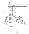
- Fig. 1 shows a highly schematic representation of a device 1 for handling containers 2 ( Fig. 2 ), which is formed in the illustrated embodiment as Be Daveer Her Healthll Road.
- the apparatus 1 includes a filling device 3, which may be of any conventional construction but is not provided with a means for internal flushing.
- the filling device 3 is designed as a filling carousel, in which the containers, in the illustrated embodiment plastic bottles, are filled in a circular circulation path.
- the filling device 3, the containers are fed by a first conveyor 4, which is a linear conveyor in the illustrated embodiment.
- a second conveyor 5 removes the containers 2 from the first conveyor and forwards them.
- the second conveyor 5 is preferably designed as a star conveyor.
- the inlet 2 into the filling device 3 is formed in the illustrated embodiment of an inlet star 6, which takes over the container 2 from the second conveyor 5 and forwards directly to the filling device 3.
- the filled containers 2 reach after passing through the filling device 3 via further conveyor 7, which are also designed here as a star conveyor, which then transfer them to a linear conveyor 8, which promotes the container 2 for further processing, for example, for packaging or the like.
- the inlet star 6 is provided with a device 9 for flushing the container 2, which is arranged immediately in front of the filling device 3.
- the term "immediate” is intended to define an arrangement in front of the filling device 3 that is so close to the filling device 3 that the effect of the internal flushing until it is transferred to the filling device is not lost or uneconomically reduced.
- the inlet star 6 contains at its periphery a plurality of equidistant successive brackets 10, which are formed in the illustrated embodiment like a tongs for engaging under a bead 2a at the neck of the container 2, as is usual.
- the containers 2 are thereby transported with upwardly facing filling opening, as they must be transported in the filling device 3.
- the inlet star 6 removes the containers 2 from the second conveyor 5 and transports them in the direction of the filling device 3.
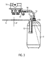
- a flushing head 11 is placed on the upwardly open container mouth, so that it substantially closes them.
- the flushing head 11 is provided with an oblique introduction of the rinsing agent, preferably CO 2 , as described in more detail in the DE 10 2005 014 076 A1 can be seen.
- the placement in a substantially vertical direction of movement A via an actuating mechanism 12, which is a lifting pivot cylinder in the illustrated embodiment and in addition to the placement movement in the direction of the double arrow A also performs a pivoting movement in the direction of the double arrow S, so that the flushing head 11, the container mouth can release, so that immediately after the inlet into the filling device 3, the filling head can be placed.
- first conduit 14 through which the detergent is sprayed from a suitable source 15 into the container 2 and there obliquely in the direction of the inner walls.
- This first line 14 may be equipped with means 17 (eg the membrane valve shown) for controlling the detergent flow.
- another line 16 passes through which the displaced from the container 2 air can escape and preferably via in an air or Spülstoffsammelkanal (not shown) another Use supplied or discharged through a silencer to the environment.
- both lines 14, 16 are flexible or movable and are preferably hoses.
- the actuating mechanism 12 is also attached to the inlet star in a suitable mounting opening 18 and rotates together with the inlet star 6 and the container 2 about the axis 6 'of the inlet star.
- a suitable mounting opening 18 and rotates together with the inlet star 6 and the container 2 about the axis 6 'of the inlet star.
- the circumferential length of the inlet or rinsing star 6, the distance between the second conveyor 5 and the filling device 3 on the circumference of the inlet star 6 and the speed of the inlet star 6 can be optimally adapted to the necessary rinsing time or the size of the container 2, without that changes to the filling device 3 are required.
- the inventive device for flushing on other inlet conveyors may be provided.
- Per filling device may also be provided with the inventive device for internal flushing inlet conveyor or inlet stars. If it is ensured that the flush does not become ineffective, the device for internal flushing can also be arranged at a certain distance from the filling device.
- any suitable means can be used as a rinsing agent.
Landscapes
- Chemical & Material Sciences (AREA)
- Chemical Kinetics & Catalysis (AREA)
- Filling Of Jars Or Cans And Processes For Cleaning And Sealing Jars (AREA)
Abstract
Description
- Die Erfindung bezieht sich auf eine Vorrichtung zum Handhaben von Behältern der im Oberbegriff von Anspruch 1 erläuterten Art.
- Eine derartige Vorrichtung ist aus der
DE 10 2005 014 076 A1 bekannt. Die bekannte Vorrichtung dient zum Innenspülen von Behältern unmittelbar vor dem Befüllen und dient vorrangig dem Zweck, vor dem Abfüllen von sauerstoffempfindlichen Getränken die Luft aus den zu befüllenden Behältern zu verdrängen, so dass das Getränk im Wesentlichen sauerstofffrei abgefüllt werden kann. Das Innenspülen erfolgt mit Gas und/oder Dampf, wobei insbesondere CO2 zum Einsatz kommt. Bei der bekannten Vorrichtung wird das Innenspülen direkt in der Befüllvorrichtung vorgenommen, was die größte zeitliche Nähe zum Befüllen bietet. Zum Innenspülen wird der Befüllkopf der Befülleinrichtung modifiziert, so dass unmittelbar vor dem Getränk durch eine in den Befüllkopf integrierte Einrichtung das Spülgas eingeblasen werden kann. Das Innenspülen nimmt jedoch eine gewisse Zeit in Anspruch, vor allen Dingen, wenn es darum geht, großvolumige Behälter zu spülen. Diese Zeit zum Innenspülen muss bei der Umlaufgeschwindigkeit bzw. dem Umlaufradius der Befülleinrichtung berücksichtigt werden. Da dabei die Spülzeit auf den größten zu befüllenden Behälter ausgelegt werden muss, arbeitet die Befülleinrichtung bei kleineren Behältern unwirtschaftlich. Ein weiterer Nachteil ergibt sich aus der Integration der Innenspül-Einrichtung in den Befüllkopf, wobei nicht auszuschließen ist, dass am Befüllkopf noch haftende Flüssigkeiten (vom Reinigen und Klarspülen) oder gar Produktreste durch das Innenspülen in den Behälter gelangen. - Der Erfindung liegt die Aufgabe zugrunde, eine Vorrichtung zum Handhaben von Behältern bereitzustellen, mit der ökonomisch und problemlos ein Innenspülen vorgenommen werden kann.
- Die Aufgabe wird durch die im Anspruch 1 angegebenen Merkmale gelöst.
- Durch die räumliche Entkopplung von Befüllvorgang und Innenspülung muss die Befüllvorrichtung nur auf die zum Befüllen notwendige Zeit ausgelegt werden, was Investitionskosten und Stellplatz spart. Darüber hinaus wird trocken gespült, wobei störende Produktreste nicht zu befürchten sind. Darüber hinaus kann auch der CO2-Verbrauch optimiert und minimiert werden.
- Vorteilhafte Weiterbildungen der Erfindung sind den Unteransprüchen zu entnehmen.
- Durch die Anordnung der Einrichtung zum Innenspülen direkt vor dem Einlauf der Befüllvorrichtung wird die Zeit zwischen dem Innenspülen und dem Aufsetzen des Befüllkopfes auf ein Minimum reduziert, so dass die Gefahr, dass Luftsauerstoff wieder in die Behälter gelangt, stark verringert wird.
- Bevorzugt befindet sich die Einrichtung zum Innenspülen an einem Einlaufstern der Befüllvorrichtung, der die gespülten Behälter anschließend direkt der Befüllvorrichtung übergibt, wobei bevorzugt pro Befüllvorrichtung mehrere Innenspül-Einrichtungen vorgesehen sind.
- Durch die Verwendung eines auf die Behältermündung aufsetzbaren Spülkopfs kann angepresst in einem geschlossenen System gespült werden, so dass die Lärm- und CO2-Belastung an der Befüllvorrichtung minimiert wird.
- Der Spülkopf kann außer einer Anheb- und Absenkbewegung auch eine Schwenkbewegung ausführen, so dass er über die Behälteröffnung geschwenkt und nach dem Spülen weggeschwenkt werden kann, um Platz für den Befüllkopf zu schaffen.
- Diese Bewegung wird bevorzugt durch ein einziges Antriebsmittel, beispielsweise einen Hebe-Schwenkzylinder bewirkt.
- Die Spülung wird optimiert, wenn der Spülkopf eine schräg zur Mittellinie des Behälters geneigte Einspülöffnung aufweist, wie dies beispielsweise in der gattungsbildenden
DE 10 2005 014 076 gezeigt ist. - Eine flexible Verbindungsleitung erlaubt die verschiedenen Bewegungen des Spülkopfs.
- Die erfindungsgemäße Vorrichtung eignet sich besonders zum Befüllen von Flaschen mit einem sauerstoffempfindlichen Getränk, wobei die Flaschen vor dem Befüllen mit CO2 gespült werden. Die Erfindung ist jedoch auch bei anderen Vorrichtungen zum Handhaben von Behältern brauchbar.
- Ein Ausführungsbeispiel der Erfindung wird nachfolgend anhand der Zeichnungen näher erläutert. Es zeigen:
- Fig. 1
- eine schematische Draufsicht auf eine erfindungsgemäße Vorrichtung,
- Fig. 2
- eine perspektivische Darstellung eines Einlaufsterns mit der erfindungsgemäßen Vorrichtung, und
- Fig. 3
- die Seitenansicht der
Fig. 2 . -
Fig. 1 zeigt in stark schematisierter Darstellung eine Vorrichtung 1 zum Handhaben von Behältern 2 (Fig. 2 ), die im dargestellten Ausführungsbeispiel als Behälterfülleinrichtung ausgebildet ist. Die Vorrichtung 1 enthält eine Befüllvorrichtung 3, die jede herkömmliche Konstruktion aufweisen kann, jedoch nicht mit einer Einrichtung zum Innenspülen versehen ist. Die Befüllvorrichtung 3 ist als Befüllkarussell ausgebildet, bei dem die Behälter, im dargestellten Ausführungsbeispiel Kunststoff-Flaschen, in einem kreisförmigen Umlaufweg befüllt werden. - Der Befüllvorrichtung 3 werden die Behälter durch einen ersten Förderer 4 zugeführt, der im dargestellten Ausführungsbeispiel ein Linearförderer ist. Ein zweiter Förderer 5 nimmt die Behälter 2 vom ersten Förderer ab und leitet sie weiter. Der zweite Förderer 5 ist bevorzugt als Sternförderer ausgebildet.
- Der zweite Förderer 5 übergibt die Behälter 2 dem Einlauf in die Befüllvorrichtung 3. Der Einlauf in die Befüllvorrichtung 3 wird im dargestellten Ausführungsbeispiel von einem Einlaufstern 6 gebildet, der die Behälter 2 vom zweiten Förderer 5 übernimmt und direkt an die Befüllvorrichtung 3 weiterleitet. Die befüllten Behälter 2 gelangen nach dem Durchlaufen der Befüllvorrichtung 3 über weitere Förderer 7, die auch hier als Sternförderer ausgebildet sind, die sie dann auf einen Linearförderer 8 übergeben, der die Behälter 2 zur Weiterverarbeitung, beispielsweise zur Verpackung oder dergleichen, fördert.
- Der Einlaufstern 6 ist mit einer Einrichtung 9 zum Innenspülen der Behälter 2 versehen, die unmittelbar vor der Befülleinrichtung 3 angeordnet ist. Der Begriff "unmittelbar" soll eine Anordnung vor der Befüllvorrichtung 3 definieren, die so nahe an der Befüllvorrichtung 3 liegt, dass die Wirkung der Innenspülung bis zur Übergabe an die Befüllvorrichtung nicht verloren geht oder unökonomisch reduziert wird.
- Der Einlaufstern 6 enthält an seinem Umfang eine Mehrzahl in gleichem Abstand aufeinanderfolgende Halterungen 10, die im dargestellten Ausführungsbeispiel zangenartig zum Untergreifen einer Wulst 2a am Hals des Behälters 2 ausgebildet sind, wie dies üblich ist. Die Behälter 2 werden dadurch mit nach oben weisender Befüllöffnung transportiert, wie sie auch in der Befülleinrichtung 3 transportiert werden müssen. Der Einlaufstern 6 nimmt die Behälter 2 vom zweiten Förderer 5 ab und transportiert sie in Richtung auf die Befüllvorrichtung 3.
- Während sich die Behälter 2 auf dem Sternförderer 6 befinden, vor der Übergabe an die Befüllvorrichtung 3, wird ein Spülkopf 11 auf die nach oben offene Behältermündung aufgesetzt, so dass er diese im Wesentlichen verschließt. Der Spülkopf 11 ist mit einer schrägen Einleitung des Spülmittels, bevorzugt CO2, versehen, wie dies in näheren Einzelheiten der
DE 10 2005 014 076 A1 zu entnehmen ist. Das Aufsetzen in einer im Wesentlichen senkrechten Bewegungsrichtung A erfolgt über einen Betätigungsmechanismus 12, der im dargestellten Ausführungsbeispiel ein Hebe-Schwenkzylinder ist und außer der Aufsetzbewegung in Richtung des Doppelpfeils A auch eine Schwenkbewegung in Richtung des Doppelpfeils S ausführt, so dass der Spülkopf 11 die Behältermündung freigeben kann, so dass unmittelbar nach dem Einlauf in die Befüllvorrichtung 3 der Befüllkopf aufgesetzt werden kann. Die Schwenkbewegung wird durch einen Arm 13 ermöglicht, der mit einem Ende mit dem Betätigungsmechanismus 12 und mit dem anderen Ende mit dem Spülkopf 11 verbunden ist. Durch den Spülkopf tritt eine erste Leitung 14 hindurch, durch die das Spülmittel aus einer geeigneten Quelle 15 in den Behälter 2 und dort schräg in Richtung auf die Innenwände gesprüht wird. Diese erste Leitung 14 kann mit Mitteln 17 (z. B. das dargestellte Membranventil) zur Regelung des Spülmitteldurchflusses ausgestattet sein. Durch den Sprühkopf 11 tritt eine weitere Leitung 16 hindurch, durch welche die aus dem Behälter 2 verdrängte Luft entweichen kann und bevorzugt über in einen Luft- oder Spülmittelsammelkanal (nicht gezeigt) einer weiteren Verwendung zugeführt oder über einen Schalldämpfer an die Umgebung abgegeben wird. Um die Bewegungen in den Richtungen A und S zu gestatten, sind beide Leitungen 14, 16 flexibel bzw. bewegbar ausgebildet und sind bevorzugt Schläuche. - Der Betätigungsmechanismus 12 ist ebenfalls am Einlaufstern in einer geeigneten Montageöffnung 18 befestigt und dreht sich zusammen mit dem Einlaufstern 6 und dem Behälter 2 um die Achse 6' des Einlaufsterns. Obwohl in
Fig. 2 nur ein Behälter und ein Betätigungsmechanismus zu sehen ist, kann jede der Halterungen 10 des Einlaufsternes 6 zwischen dem zweiten Förderer 5 und der Befüllvorrichtung 3 im ordnungsgemäßen Betrieb mit jeweils einem Behälter 2 besetzt sein, wobei jede Montageöffnung 18 des Einlaufsterns 6 einen Betätigungsmechanismus 12 trägt. Die Umfangslänge des Einlauf- bzw. Spülsterns 6, der Abstand zwischen dem zweiten Förderer 5 und der Befülleinrichtung 3 auf dem Umfang des Einlaufsterns 6 und die Geschwindigkeit des Einlaufsterns 6 können auf die notwendige Spülzeit bzw. die Größe der Behälter 2 optimal abgestimmt werden, ohne dass es Änderungen an der Befüllvorrichtung 3 bedarf. - In Abwandlung des beschriebenen und gezeichneten Ausführungsbeispiels kann die erfindungsgemäße Einrichtung zum Innenspülen auch auf anderen Einlaufförderern, und nicht nur auf Einlaufsternen, vorgesehen sein. Pro Befüllvorrichtung können auch mehrere mit der erfindungsgemäßen Einrichtung zum Innenspülen versehene Einlaufförderer bzw. Einlaufsterne vorgesehen sein. Wenn sichergestellt ist, dass die Spülung nicht unwirksam wird, kann die Einrichtung zum Innenspülen auch in einem gewissen Abstand zur Befüllvorrichtung angeordnet sein. Als Spülmittel kann jedes geeignete Mittel eingesetzt werden.
Claims (11)
- Vorrichtung (1) zum Handhaben von Behältern (2), mit einer Befüllvorrichtung (3) zum Befüllen der Behälter (2), einem Transportweg (4, 5, 6) auf dem die Behälter (2) der Befülleinrichtung (3) zuführbar sind, und einer Einrichtung (9) zum Innenspülen der Behälter, dadurch gekennzeichnet, dass die Einrichtung (9) zum Innenspülen im Transportweg (4, 5, 6) unmittelbar vor der Befülleinrichtung (3) vorgesehen ist.
- Vorrichtung nach Anspruch 1, dadurch gekennzeichnet, dass die Einrichtung (9) zum Innenspülen dem Einlauf der Befüllvorrichtung (3) vorgeschaltet ist.
- Vorrichtung nach Anspruch 1, dadurch gekennzeichnet, dass die Einrichtung (9) zum Innenspülen an einem Einlaufstern (6) der Befüllvorrichtung (3) vorgesehen ist.
- Vorrichtung nach einem der Ansprüche 1 bis 3, dadurch gekennzeichnet, dass der Befüllvorrichtung (3) eine Mehrzahl von Einrichtungen (9) zum Innenspülen zugeordnet ist.
- Vorrichtung nach einem der Ansprüche 1 bis 4, dadurch gekennzeichnet, dass die Einrichtung (9) zum Innenspülen einen auf die Behältermündung aufsetzbaren Spülkopf (11) enthält.
- Vorrichtung nach einem der Ansprüche 1 bis 5, dadurch gekennzeichnet, dass die Einrichtung (9) zum Innenspülen einen über die Behältermündung schwenkbaren Spülkopf (11) enthält.
- Vorrichtung nach Anspruch 5 oder 6, dadurch gekennzeichnet, dass der Spülkopf (11) mittels Hebe-Schwenkzylinder (12) auf die Behältermündung aufsetzbar ist.
- Vorrichtung nach einem der Ansprüche 5 bis 7, dadurch gekennzeichnet, dass der Spülkopf (11) eine schräg zur Mittellinie des Behälters (2) geneigte Einspülöffnung aufweist.
- Vorrichtung nach einem der Ansprüche 5 bis 8, dadurch gekennzeichnet, dass der Spülkopf (11) über eine flexible Leitung (14) mit einer Spülmittelquelle (15) verbunden ist.
- Vorrichtung nach einem der Ansprüche 1 bis 9, dadurch gekennzeichnet, dass die Einrichtung (9) zum Innenspülen zum Spülen der Behälter mit CO2 ausgebildet ist.
- Vorrichtung nach einem der Ansprüche 1 bis 10, gekennzeichnet durch ihre Ausgestaltung zum Handhaben von Flaschen zum Befüllen mit einem sauerstoffempfindlichen Getränk.
Priority Applications (1)
| Application Number | Priority Date | Filing Date | Title |
|---|---|---|---|
| SI200930685T SI2112121T1 (sl) | 2008-04-22 | 2009-03-04 | Naprava za rokovanje s posodami |
Applications Claiming Priority (1)
| Application Number | Priority Date | Filing Date | Title |
|---|---|---|---|
| DE102008020118A DE102008020118A1 (de) | 2008-04-22 | 2008-04-22 | Vorrichtung zum Handhaben von Behältern |
Publications (2)
| Publication Number | Publication Date |
|---|---|
| EP2112121A1 true EP2112121A1 (de) | 2009-10-28 |
| EP2112121B1 EP2112121B1 (de) | 2013-06-12 |
Family
ID=40935021
Family Applications (1)
| Application Number | Title | Priority Date | Filing Date |
|---|---|---|---|
| EP20090003119 Active EP2112121B1 (de) | 2008-04-22 | 2009-03-04 | Vorrichtung zum Handhaben von Behältern |
Country Status (3)
| Country | Link |
|---|---|
| EP (1) | EP2112121B1 (de) |
| DE (1) | DE102008020118A1 (de) |
| SI (1) | SI2112121T1 (de) |
Citations (4)
| Publication number | Priority date | Publication date | Assignee | Title |
|---|---|---|---|---|
| DE1782777A1 (de) * | 1965-12-13 | 1972-10-26 | Evers Heinz Dipl Ing Dr | Vorrichtung zum Fuellen und Verschliessen und gegebenenfalls vorherigen Evakuieren und Vorspuelen von Kunststoffflaschen |
| EP0319504A1 (de) | 1987-12-04 | 1989-06-07 | KabiVitrum AB | Vorrichtung zum Füllen und Verschliessen von Flaschen |
| EP0448245A1 (de) * | 1990-03-14 | 1991-09-25 | The BOC Group plc | Gasabgabevorrichtung und Verfahren |
| DE4427577A1 (de) * | 1994-08-04 | 1996-02-08 | Kronseder Maschf Krones | Verfahren und Vorrichtung zur Kontrolle einer thermischen Behandlung von Flaschen o. dgl. |
Family Cites Families (2)
| Publication number | Priority date | Publication date | Assignee | Title |
|---|---|---|---|---|
| DE7202299U (de) * | 1974-06-12 | Holstein & Kappert Maschinenfabrik Phoenix Gmbh | Füllmaschine zum Abfüllen luftempfindlicher Getränke | |
| DE102005014076A1 (de) | 2005-03-23 | 2006-10-05 | Krones Ag | Verfahren und Vorrichtung zum Spülen von Gefässen, insbesondere von Flaschen, mit einem gasförmigen Medium |
-
2008
- 2008-04-22 DE DE102008020118A patent/DE102008020118A1/de not_active Withdrawn
-
2009
- 2009-03-04 EP EP20090003119 patent/EP2112121B1/de active Active
- 2009-03-04 SI SI200930685T patent/SI2112121T1/sl unknown
Patent Citations (4)
| Publication number | Priority date | Publication date | Assignee | Title |
|---|---|---|---|---|
| DE1782777A1 (de) * | 1965-12-13 | 1972-10-26 | Evers Heinz Dipl Ing Dr | Vorrichtung zum Fuellen und Verschliessen und gegebenenfalls vorherigen Evakuieren und Vorspuelen von Kunststoffflaschen |
| EP0319504A1 (de) | 1987-12-04 | 1989-06-07 | KabiVitrum AB | Vorrichtung zum Füllen und Verschliessen von Flaschen |
| EP0448245A1 (de) * | 1990-03-14 | 1991-09-25 | The BOC Group plc | Gasabgabevorrichtung und Verfahren |
| DE4427577A1 (de) * | 1994-08-04 | 1996-02-08 | Kronseder Maschf Krones | Verfahren und Vorrichtung zur Kontrolle einer thermischen Behandlung von Flaschen o. dgl. |
Also Published As
| Publication number | Publication date |
|---|---|
| EP2112121B1 (de) | 2013-06-12 |
| SI2112121T1 (sl) | 2013-09-30 |
| DE102008020118A1 (de) | 2009-10-29 |
Similar Documents
| Publication | Publication Date | Title |
|---|---|---|
| EP2628707B1 (de) | Verfahren und Vorrichtung zum Transportieren von Behältern | |
| EP2797834B1 (de) | Vorrichtung und verfahren zum befüllen, verschliessen und etikettieren von behältnissen | |
| EP3094590A1 (de) | Behälterbehandlungsmaschine zum behandeln von behältern | |
| WO2014139641A1 (de) | Verfahren sowie füllmaschine zum füllen von dosen oder dgl. behältern mit einem flüssigen füllgut | |
| DE102020116779A1 (de) | Behälterbehandlungsvorrichtung | |
| EP3137410B1 (de) | Behälterbehandlungsmaschine sowie verfahren zum behandeln von behältern | |
| EP2429728B1 (de) | Verfahren und vorrichtung zur innenreinigung von dosen mit jeweiliger öffnung | |
| WO2010009796A2 (de) | Verfahren zur handhabung von behältern während des transportes durch abfüllanlagen | |
| EP2340131B1 (de) | Vorrichtung zum verschwenken einer in einem greifer geförderten flasche | |
| EP0623527A1 (de) | Schüttgutbehälter mit Bodenauslaufventil | |
| EP2218648A2 (de) | Vorrichtung und Verfahren zum Etikettieren von Behältern | |
| EP2669200B1 (de) | Vorrichtung zum Verschließen von Behältern mit integrierter Kopfraumbegasung | |
| EP2112121B1 (de) | Vorrichtung zum Handhaben von Behältern | |
| EP2688689B1 (de) | Vorrichtung zum abblasen von flaschenböden | |
| DE2948633A1 (de) | Vorrichtung zum verschliessen von gefaessen | |
| EP2821151B1 (de) | Vorrichtung zum Transport eines Behälters in einer Behälterreinigungsanlage | |
| EP3310400B1 (de) | Vorrichtung zur sterilbehandlung | |
| EP3516964B1 (de) | Haltevorrichtung zum halten von entweideten geflügelkörpern oder teilen davon während der bearbeitung in einer vorrichtung zur verarbeitung von entweideten geflügelkörpern oder teilen davon | |
| DE102014114268A1 (de) | Vorrichtung zum Behandeln von Behältern | |
| EP2559640B1 (de) | Greifer für Flaschen sowie Bearbeitungsmaschine mit einer Anzahl von Greifern und Verfahren zur Handhabung von Flaschen | |
| EP3642521B1 (de) | Anschlusskopf und ventilknoten | |
| EP1729053B1 (de) | Molchbare Vorrichtung für eine Förderanlage zum Fördern eines Produktes durch eine Rohrleitung | |
| EP1899258B1 (de) | Vorrichtung zur vermeidung des überschwappens gefüllter gefässe beim fördern derselben | |
| DE102024114038A1 (de) | Vorrichtung zum Füllen von Behältern und zugehöriges Betriebsverfahren | |
| DE102023109009A1 (de) | Greifereinrichtung zum Greifen von Behältern |
Legal Events
| Date | Code | Title | Description |
|---|---|---|---|
| PUAI | Public reference made under article 153(3) epc to a published international application that has entered the european phase |
Free format text: ORIGINAL CODE: 0009012 |
|
| AK | Designated contracting states |
Kind code of ref document: A1 Designated state(s): AT BE BG CH CY CZ DE DK EE ES FI FR GB GR HR HU IE IS IT LI LT LU LV MC MK MT NL NO PL PT RO SE SI SK TR |
|
| AX | Request for extension of the european patent |
Extension state: AL BA RS |
|
| 17P | Request for examination filed |
Effective date: 20091123 |
|
| AKX | Designation fees paid |
Designated state(s): AT BE BG CH CY CZ DE DK EE ES FI FR GB GR HR HU IE IS IT LI LT LU LV MC MK MT NL NO PL PT RO SE SI SK TR |
|
| GRAP | Despatch of communication of intention to grant a patent |
Free format text: ORIGINAL CODE: EPIDOSNIGR1 |
|
| GRAS | Grant fee paid |
Free format text: ORIGINAL CODE: EPIDOSNIGR3 |
|
| GRAA | (expected) grant |
Free format text: ORIGINAL CODE: 0009210 |
|
| AK | Designated contracting states |
Kind code of ref document: B1 Designated state(s): AT BE BG CH CY CZ DE DK EE ES FI FR GB GR HR HU IE IS IT LI LT LU LV MC MK MT NL NO PL PT RO SE SI SK TR |
|
| REG | Reference to a national code |
Ref country code: GB Ref legal event code: FG4D Free format text: NOT ENGLISH |
|
| REG | Reference to a national code |
Ref country code: CH Ref legal event code: EP |
|
| REG | Reference to a national code |
Ref country code: AT Ref legal event code: REF Ref document number: 616623 Country of ref document: AT Kind code of ref document: T Effective date: 20130615 |
|
| REG | Reference to a national code |
Ref country code: IE Ref legal event code: FG4D Free format text: LANGUAGE OF EP DOCUMENT: GERMAN |
|
| REG | Reference to a national code |
Ref country code: DE Ref legal event code: R096 Ref document number: 502009007312 Country of ref document: DE Effective date: 20130808 |
|
| PG25 | Lapsed in a contracting state [announced via postgrant information from national office to epo] |
Ref country code: LT Free format text: LAPSE BECAUSE OF FAILURE TO SUBMIT A TRANSLATION OF THE DESCRIPTION OR TO PAY THE FEE WITHIN THE PRESCRIBED TIME-LIMIT Effective date: 20130612 Ref country code: SE Free format text: LAPSE BECAUSE OF FAILURE TO SUBMIT A TRANSLATION OF THE DESCRIPTION OR TO PAY THE FEE WITHIN THE PRESCRIBED TIME-LIMIT Effective date: 20130612 Ref country code: FI Free format text: LAPSE BECAUSE OF FAILURE TO SUBMIT A TRANSLATION OF THE DESCRIPTION OR TO PAY THE FEE WITHIN THE PRESCRIBED TIME-LIMIT Effective date: 20130612 Ref country code: NO Free format text: LAPSE BECAUSE OF FAILURE TO SUBMIT A TRANSLATION OF THE DESCRIPTION OR TO PAY THE FEE WITHIN THE PRESCRIBED TIME-LIMIT Effective date: 20130912 Ref country code: ES Free format text: LAPSE BECAUSE OF FAILURE TO SUBMIT A TRANSLATION OF THE DESCRIPTION OR TO PAY THE FEE WITHIN THE PRESCRIBED TIME-LIMIT Effective date: 20130923 Ref country code: GR Free format text: LAPSE BECAUSE OF FAILURE TO SUBMIT A TRANSLATION OF THE DESCRIPTION OR TO PAY THE FEE WITHIN THE PRESCRIBED TIME-LIMIT Effective date: 20130913 |
|
| REG | Reference to a national code |
Ref country code: NL Ref legal event code: VDEP Effective date: 20130612 |
|
| REG | Reference to a national code |
Ref country code: LT Ref legal event code: MG4D |
|
| PG25 | Lapsed in a contracting state [announced via postgrant information from national office to epo] |
Ref country code: BG Free format text: LAPSE BECAUSE OF FAILURE TO SUBMIT A TRANSLATION OF THE DESCRIPTION OR TO PAY THE FEE WITHIN THE PRESCRIBED TIME-LIMIT Effective date: 20130912 Ref country code: HR Free format text: LAPSE BECAUSE OF FAILURE TO SUBMIT A TRANSLATION OF THE DESCRIPTION OR TO PAY THE FEE WITHIN THE PRESCRIBED TIME-LIMIT Effective date: 20130612 |
|
| PG25 | Lapsed in a contracting state [announced via postgrant information from national office to epo] |
Ref country code: LV Free format text: LAPSE BECAUSE OF FAILURE TO SUBMIT A TRANSLATION OF THE DESCRIPTION OR TO PAY THE FEE WITHIN THE PRESCRIBED TIME-LIMIT Effective date: 20130612 |
|
| PG25 | Lapsed in a contracting state [announced via postgrant information from national office to epo] |
Ref country code: CZ Free format text: LAPSE BECAUSE OF FAILURE TO SUBMIT A TRANSLATION OF THE DESCRIPTION OR TO PAY THE FEE WITHIN THE PRESCRIBED TIME-LIMIT Effective date: 20130612 Ref country code: PT Free format text: LAPSE BECAUSE OF FAILURE TO SUBMIT A TRANSLATION OF THE DESCRIPTION OR TO PAY THE FEE WITHIN THE PRESCRIBED TIME-LIMIT Effective date: 20131014 Ref country code: IS Free format text: LAPSE BECAUSE OF FAILURE TO SUBMIT A TRANSLATION OF THE DESCRIPTION OR TO PAY THE FEE WITHIN THE PRESCRIBED TIME-LIMIT Effective date: 20131012 Ref country code: EE Free format text: LAPSE BECAUSE OF FAILURE TO SUBMIT A TRANSLATION OF THE DESCRIPTION OR TO PAY THE FEE WITHIN THE PRESCRIBED TIME-LIMIT Effective date: 20130612 Ref country code: SK Free format text: LAPSE BECAUSE OF FAILURE TO SUBMIT A TRANSLATION OF THE DESCRIPTION OR TO PAY THE FEE WITHIN THE PRESCRIBED TIME-LIMIT Effective date: 20130612 |
|
| PG25 | Lapsed in a contracting state [announced via postgrant information from national office to epo] |
Ref country code: NL Free format text: LAPSE BECAUSE OF FAILURE TO SUBMIT A TRANSLATION OF THE DESCRIPTION OR TO PAY THE FEE WITHIN THE PRESCRIBED TIME-LIMIT Effective date: 20130612 Ref country code: PL Free format text: LAPSE BECAUSE OF FAILURE TO SUBMIT A TRANSLATION OF THE DESCRIPTION OR TO PAY THE FEE WITHIN THE PRESCRIBED TIME-LIMIT Effective date: 20130612 Ref country code: RO Free format text: LAPSE BECAUSE OF FAILURE TO SUBMIT A TRANSLATION OF THE DESCRIPTION OR TO PAY THE FEE WITHIN THE PRESCRIBED TIME-LIMIT Effective date: 20130612 |
|
| PLBE | No opposition filed within time limit |
Free format text: ORIGINAL CODE: 0009261 |
|
| STAA | Information on the status of an ep patent application or granted ep patent |
Free format text: STATUS: NO OPPOSITION FILED WITHIN TIME LIMIT |
|
| PG25 | Lapsed in a contracting state [announced via postgrant information from national office to epo] |
Ref country code: DK Free format text: LAPSE BECAUSE OF FAILURE TO SUBMIT A TRANSLATION OF THE DESCRIPTION OR TO PAY THE FEE WITHIN THE PRESCRIBED TIME-LIMIT Effective date: 20130612 |
|
| 26N | No opposition filed |
Effective date: 20140313 |
|
| REG | Reference to a national code |
Ref country code: DE Ref legal event code: R097 Ref document number: 502009007312 Country of ref document: DE Effective date: 20140313 |
|
| PG25 | Lapsed in a contracting state [announced via postgrant information from national office to epo] |
Ref country code: LU Free format text: LAPSE BECAUSE OF FAILURE TO SUBMIT A TRANSLATION OF THE DESCRIPTION OR TO PAY THE FEE WITHIN THE PRESCRIBED TIME-LIMIT Effective date: 20140304 |
|
| REG | Reference to a national code |
Ref country code: CH Ref legal event code: PL |
|
| GBPC | Gb: european patent ceased through non-payment of renewal fee |
Effective date: 20140304 |
|
| REG | Reference to a national code |
Ref country code: IE Ref legal event code: MM4A |
|
| PG25 | Lapsed in a contracting state [announced via postgrant information from national office to epo] |
Ref country code: CH Free format text: LAPSE BECAUSE OF NON-PAYMENT OF DUE FEES Effective date: 20140331 Ref country code: GB Free format text: LAPSE BECAUSE OF NON-PAYMENT OF DUE FEES Effective date: 20140304 Ref country code: IE Free format text: LAPSE BECAUSE OF NON-PAYMENT OF DUE FEES Effective date: 20140304 Ref country code: LI Free format text: LAPSE BECAUSE OF NON-PAYMENT OF DUE FEES Effective date: 20140331 |
|
| REG | Reference to a national code |
Ref country code: AT Ref legal event code: MM01 Ref document number: 616623 Country of ref document: AT Kind code of ref document: T Effective date: 20140304 |
|
| PG25 | Lapsed in a contracting state [announced via postgrant information from national office to epo] |
Ref country code: AT Free format text: LAPSE BECAUSE OF NON-PAYMENT OF DUE FEES Effective date: 20140304 |
|
| REG | Reference to a national code |
Ref country code: FR Ref legal event code: PLFP Year of fee payment: 8 |
|
| PG25 | Lapsed in a contracting state [announced via postgrant information from national office to epo] |
Ref country code: MT Free format text: LAPSE BECAUSE OF FAILURE TO SUBMIT A TRANSLATION OF THE DESCRIPTION OR TO PAY THE FEE WITHIN THE PRESCRIBED TIME-LIMIT Effective date: 20130612 |
|
| PG25 | Lapsed in a contracting state [announced via postgrant information from national office to epo] |
Ref country code: MC Free format text: LAPSE BECAUSE OF FAILURE TO SUBMIT A TRANSLATION OF THE DESCRIPTION OR TO PAY THE FEE WITHIN THE PRESCRIBED TIME-LIMIT Effective date: 20130612 |
|
| PGFP | Annual fee paid to national office [announced via postgrant information from national office to epo] |
Ref country code: SI Payment date: 20160216 Year of fee payment: 8 |
|
| PG25 | Lapsed in a contracting state [announced via postgrant information from national office to epo] |
Ref country code: CY Free format text: LAPSE BECAUSE OF FAILURE TO SUBMIT A TRANSLATION OF THE DESCRIPTION OR TO PAY THE FEE WITHIN THE PRESCRIBED TIME-LIMIT Effective date: 20130612 |
|
| PG25 | Lapsed in a contracting state [announced via postgrant information from national office to epo] |
Ref country code: BE Free format text: LAPSE BECAUSE OF FAILURE TO SUBMIT A TRANSLATION OF THE DESCRIPTION OR TO PAY THE FEE WITHIN THE PRESCRIBED TIME-LIMIT Effective date: 20140331 Ref country code: HU Free format text: LAPSE BECAUSE OF FAILURE TO SUBMIT A TRANSLATION OF THE DESCRIPTION OR TO PAY THE FEE WITHIN THE PRESCRIBED TIME-LIMIT; INVALID AB INITIO Effective date: 20090304 Ref country code: TR Free format text: LAPSE BECAUSE OF FAILURE TO SUBMIT A TRANSLATION OF THE DESCRIPTION OR TO PAY THE FEE WITHIN THE PRESCRIBED TIME-LIMIT Effective date: 20130612 |
|
| REG | Reference to a national code |
Ref country code: FR Ref legal event code: PLFP Year of fee payment: 9 |
|
| PG25 | Lapsed in a contracting state [announced via postgrant information from national office to epo] |
Ref country code: SI Free format text: LAPSE BECAUSE OF NON-PAYMENT OF DUE FEES Effective date: 20170305 |
|
| REG | Reference to a national code |
Ref country code: SI Ref legal event code: KO00 Effective date: 20171208 |
|
| REG | Reference to a national code |
Ref country code: FR Ref legal event code: PLFP Year of fee payment: 10 |
|
| PG25 | Lapsed in a contracting state [announced via postgrant information from national office to epo] |
Ref country code: MK Free format text: LAPSE BECAUSE OF FAILURE TO SUBMIT A TRANSLATION OF THE DESCRIPTION OR TO PAY THE FEE WITHIN THE PRESCRIBED TIME-LIMIT Effective date: 20130612 |
|
| P01 | Opt-out of the competence of the unified patent court (upc) registered |
Effective date: 20230523 |
|
| PGFP | Annual fee paid to national office [announced via postgrant information from national office to epo] |
Ref country code: DE Payment date: 20260204 Year of fee payment: 18 |
|
| PGFP | Annual fee paid to national office [announced via postgrant information from national office to epo] |
Ref country code: IT Payment date: 20260220 Year of fee payment: 18 |
|
| PGFP | Annual fee paid to national office [announced via postgrant information from national office to epo] |
Ref country code: FR Payment date: 20260209 Year of fee payment: 18 |