EP2112101A1 - Dispositif et procédé destinés à la palettisation d'assemblages de marchandises au détail - Google Patents
Dispositif et procédé destinés à la palettisation d'assemblages de marchandises au détail Download PDFInfo
- Publication number
- EP2112101A1 EP2112101A1 EP09156008A EP09156008A EP2112101A1 EP 2112101 A1 EP2112101 A1 EP 2112101A1 EP 09156008 A EP09156008 A EP 09156008A EP 09156008 A EP09156008 A EP 09156008A EP 2112101 A1 EP2112101 A1 EP 2112101A1
- Authority
- EP
- European Patent Office
- Prior art keywords
- strip
- piece goods
- transport
- intermediate layers
- unit
- Prior art date
- Legal status (The legal status is an assumption and is not a legal conclusion. Google has not performed a legal analysis and makes no representation as to the accuracy of the status listed.)
- Granted
Links
- 238000000034 method Methods 0.000 title claims abstract description 24
- 239000000463 material Substances 0.000 claims abstract description 78
- 238000005520 cutting process Methods 0.000 claims abstract description 20
- 238000003780 insertion Methods 0.000 claims description 6
- 230000037431 insertion Effects 0.000 claims description 6
- 230000000712 assembly Effects 0.000 claims description 5
- 238000000429 assembly Methods 0.000 claims description 5
- 238000000926 separation method Methods 0.000 claims description 5
- 239000010410 layer Substances 0.000 description 62
- 230000008878 coupling Effects 0.000 description 24
- 238000010168 coupling process Methods 0.000 description 24
- 238000005859 coupling reaction Methods 0.000 description 24
- 238000006073 displacement reaction Methods 0.000 description 4
- 238000009826 distribution Methods 0.000 description 3
- 238000011161 development Methods 0.000 description 2
- 230000018109 developmental process Effects 0.000 description 2
- 238000005096 rolling process Methods 0.000 description 2
- 230000001133 acceleration Effects 0.000 description 1
- 230000005540 biological transmission Effects 0.000 description 1
- 239000011111 cardboard Substances 0.000 description 1
- 238000004891 communication Methods 0.000 description 1
- 230000001419 dependent effect Effects 0.000 description 1
- 239000012530 fluid Substances 0.000 description 1
- 239000011229 interlayer Substances 0.000 description 1
- 238000004806 packaging method and process Methods 0.000 description 1
- 239000011087 paperboard Substances 0.000 description 1
- 238000003860 storage Methods 0.000 description 1
- 230000001360 synchronised effect Effects 0.000 description 1
- 238000012546 transfer Methods 0.000 description 1
- 230000007704 transition Effects 0.000 description 1
- 238000009827 uniform distribution Methods 0.000 description 1
Images


Classifications
-
- B—PERFORMING OPERATIONS; TRANSPORTING
- B65—CONVEYING; PACKING; STORING; HANDLING THIN OR FILAMENTARY MATERIAL
- B65G—TRANSPORT OR STORAGE DEVICES, e.g. CONVEYORS FOR LOADING OR TIPPING, SHOP CONVEYOR SYSTEMS OR PNEUMATIC TUBE CONVEYORS
- B65G57/00—Stacking of articles
- B65G57/005—Stacking of articles by using insertions or spacers between the stacked layers
-
- B—PERFORMING OPERATIONS; TRANSPORTING
- B65—CONVEYING; PACKING; STORING; HANDLING THIN OR FILAMENTARY MATERIAL
- B65G—TRANSPORT OR STORAGE DEVICES, e.g. CONVEYORS FOR LOADING OR TIPPING, SHOP CONVEYOR SYSTEMS OR PNEUMATIC TUBE CONVEYORS
- B65G57/00—Stacking of articles
- B65G57/02—Stacking of articles by adding to the top of the stack
- B65G57/16—Stacking of articles of particular shape
- B65G57/20—Stacking of articles of particular shape three-dimensional, e.g. cubiform, cylindrical
- B65G57/22—Stacking of articles of particular shape three-dimensional, e.g. cubiform, cylindrical in layers each of predetermined arrangement
- B65G57/24—Stacking of articles of particular shape three-dimensional, e.g. cubiform, cylindrical in layers each of predetermined arrangement the layers being transferred as a whole, e.g. on pallets
Definitions
- the present invention relates to an apparatus and a method for palletizing piece goods assemblies.
- Palletizers are known in the art. In this case, an empty pallet is first provided in a loading station for loading a pallet, and then layerwise containers such as crates, disposable containers or the like are placed on them. Usually, interlayers are arranged, for example, made of paper or cardboard between individual bundle layers.
- a device for loading pallets with cargo is known. This device has transverse to a sheet transfer direction extending support rails in which a support plane is guided.
- a device for dissolving and forming piece stacks is known.
- This device has a plurality of vacuum grippers, which grip the piece goods themselves from above.
- a support plane in the form of a roller carpet is provided, which can be moved under the cargo position.
- terminal strips are provided to clamp the cargo items.
- the present invention is therefore based on the object to provide a Palletierstrom available, which allows a higher Palletier effet.
- a device for forming stacks of piece goods compilations has a movable transport device for transporting the piece goods compilation, as well as a pre-insertion unit for bringing intermediate layers to the piece goods compilation.
- the device is designed such that it takes over an elongated strip of material consisting of the material of the intermediate layers, wherein the intermediate layers are separable from this elongated strip of material and preferably the device has a separating device which separates the intermediate layers of the strip of material.
- the device preferably has a first reservoir or a first dispensing device, which receives the elongate strip of material, and the pre-guide unit is designed such that it takes over the elongate strip of material from this reservoir.
- a portion of the delivery unit is located immediately adjacent to the reservoir.
- a reservoir is understood to mean any receiving unit for the intermediate layers.
- the reservoir to a storage unit or the ground on which a stack or the strip of material is stored.
- it is an at least partially open housing or frame from which the strip of material can be pulled out.
- the reservoir receives the strip of material in multiply folded form.
- These are preferably a so-called endless strip, which in each case at regular intervals is again bent over in such a way that the strip turns by 180 ° in each case and in this way a stack is formed.
- the reservoir can be carried out very easily, in particular without unwinding unit such as rollers or the like.
- the reservoir has a cavity whose cross-section is larger than the area which is formed by the width of the strip of material and the distance between two folds on which the strip of material is folded over.
- the cavity can also be formed by limiting rods of a frame. In this cavity, the multi-folded endless strip can be arranged lying.
- the reservoir preferably has a removal region, over which the strip of material is removed, this removal region being arranged above an upper end of a multiply folded strip of material.
- the separating device has a cutting unit, which preferably cuts the strip of material in a direction perpendicular to the transport direction of the strip of material extending direction.
- a heatable wire could be used, which cuts through the strip of material in each case at the predetermined locations.
- the device has a first roller unit with two opposing rollers, between which the strip of material can be guided. Preferably, at least one of the two rollers is driven. However, it would also be possible that the two rollers are not driven and only pulled through by a further drive direction of the strip of material. Through these two rollers, a particularly precise guidance of the material strip is achieved. By feeding the material strip, the position of the strip of material and thus also of the intermediate layers can furthermore be specified very precisely.
- the device has a second roller unit with two opposing rollers, between which the strip of material can be guided. Preferably, these two roller units are arranged one behind the other in the transport direction of the material strip.
- a conveyor belt connects to the two roller units, which introduces the now cut intermediate layers to the piece goods compilation or leads under this piece goods compilation.
- the separating device or a cutting or separating element of the separating device between the first roller unit and the second roller unit is arranged.
- a particularly accurate burning or cutting process of the strip of material is achieved and in this way a precise dimensioning of the intermediate layer can be achieved.
- at least one of the two rollers of the second roller unit is driven to achieve in this way a feed of the intermediate layer.
- the device has a second reservoir, which receives an elongated strip of material.
- a second reservoir which receives an elongated strip of material.
- two mutually parallel reservoirs are provided, which ensure a seamless transition when, for example, one of the two strips of material is over.
- the pre-guide unit is designed such that it takes over the strip of material from the reservoir.
- a support device which is movable under the piece goods compilation and which is substantially completely removable from a lying below the piece item compilation area.
- the transport device has at least one controllable fixing device for temporarily fixing an intermediate layer, wherein this fixing device is movable below the support device for fixing the intermediate layer.
- the transport device for the piece goods assemblies or the package layers is combined with a fixing device for the intermediate layer to be arranged between the package layers.
- a stack can be formed faster with the help of only one device.
- the pallets to be palleted to containers For palletizing, for example, with the aid of the device according to the invention, initially an intermediate layer can be deposited and then a piece-goods combination and then this process can be repeated above the clipboard. Thus, a significant acceleration of this method can be achieved.
- the feeder transversely feeds the piece goods assembly of the transport means, i. the piece goods combination is guided essentially in a horizontal direction.
- the transport device preferably has a lateral opening through which the piece goods compilation can be pushed into the transport device. Moving under the piece-goods compilation means that the fixing device can be moved to a position which is lower than the piece-goods compilation. It is also conceivable that the fixing device within an area which is below the piece goods compilation, is moved.
- a fixing device is understood to mean a device which is capable of holding an intermediate layer at least temporarily on the transport device.
- the fixing device is integrated into the support device such that its movement is coupled to the movement of the support device.
- the fixing device for carrying out the fixing operation is arranged in a region which lies below the support device, so that the intermediate layer can be held below the piece goods compilation.
- the support means on a plurality of rotatable bodies which can be supported against the Indeedgutzzusammengnally.
- the aforementioned rotatable bodies are provided, which allow a rolling against the piece goods compilation.
- the support device in the plane of a bottom surface of the piece goods compilation is movable relative to the piece goods compilation. More specifically, it is possible to move the support device like a curtain against the Indeedgutzzusammengnagna.
- the rotatable bodies or these rotatable body bearing shafts or axles are guided in two-sided rails.
- the fixing device has at least one fixing element, which is arranged between two rotatable bodies. More specifically, the fixing members are integrated in the curtain formed of a plurality of rotatable bodies.
- the fixing device on a strip-shaped body which is movable in two lateral rails together with the rotatable bodies.
- a strip-shaped body for example, can be arranged between two rotatable bodies and thus is displaceable together with these rotatable bodies relative to the piece goods compilation.
- At least one fixing element is a controllable suction head. It is thus proposed to mount at least one such suction head in the support device, which is preferably designed as a blind carpet. In addition, however, it would also be possible to attach a fixing device, for example in the form of a clamping device below the support means.
- a controllable suction head is understood to mean that the fixing operation can be controlled by the user or by a machine control, so that either an intermediate layer to be lifted can be picked up and released.
- the fixing device has two spaced-apart strip-shaped body, wherein at least one fixing element is arranged on each of these strip-shaped body and wherein between these two strip-shaped bodies a plurality of rotatable bodies is provided.
- each of these strip-shaped body has at least two such fixing elements.
- a plurality of such fixing elements are substantially uniformly distributed, so that a particularly efficient hold of the intermediate layers is possible.
- the support device has two mutually substantially symmetrically shaped sections. To open the bottom of the transport device, these two sections slide apart and free in this way the area below the piece goods compilation.
- the transport device is arranged in its entirety on a pivotable arm about a vertical axis. In this way, the transport device can grip piece goods compilations and store them at another location, for example on a pallet.
- the device has a pre-guide unit, which leads the intermediate layers to an underside of the support device. In this way it is achieved that the transport device, without having to be moved over long distances, can accommodate both the piece goods collection position and the intermediate layer.
- the transport device has a coupling device, which is in an operating state in fluid communication with the fixing device and which is separated in a further operating state of the fixing device of this. More precisely, this coupling device serves to provide a vacuum to the fixing elements designed as suction heads on the support device. In a closed state of the support device or of the roller carpet, the coupling device docks onto the suction strips of the support device and then this can be subjected to a vacuum.
- This coupling device is preferably also used to temporarily apply compressed air to the suction cups, in order to release in this way the respective intermediate layer of the suction cups.
- the coupling device is designed to be pivotable and can be created by this pivoting action on the strips or pulled away from them.
- the present invention is further directed to a transporting device for transporting the piece-goods assembly, comprising a support device which is movable under the piece-goods assembly and which is substantially completely removable from a region located vertically below the piece-goods combination.
- the transport device has at least one controllable fixing device for temporarily fixing an intermediate layer, wherein this fixing device for fixing the intermediate layer below the piece goods compilation is movable and wherein the fixing device is integrated into the support device such that its movement and the movement of the support device is coupled.
- a first intermediate layer in a first predetermined region with a pre-insertion unit in a first transport direction is introduced in one step. Subsequently, the Zhangzzusammengnagna is guided with a transport device in the specified area.
- the piece goods compilation is first performed in the area and only then the liner is moved under the piece goods compilation.
- the predefined area is understood in particular to be an area viewed from above in a plan view. It is therefore possible that the strip of material below (or above) of the piece goods compilation brought to this or spent in the area.
- an elongated strip of material, from which the intermediate layers can be separated is fed to the pre-insertion unit and the intermediate layers are separated from this strip of material by means of a separating device.
- a separating device it is also proposed in the method according to the invention not to supply the intermediate layers individually, but by means of an endless strip.
- the strip of material is supplied from a reservoir.
- the intermediate layers and the Simplygutzusammenstelllept be performed in each case the same area and there each arranged simultaneously ie first one Zhangzzusammen ein then an intermediate layer and then again a piece goods compilation, etc.
- the Shawgutzzusammengnagna herein is transported in a direction that is not parallel to the first transport direction.
- the direction in which the Selfgutzzusammen ein is transported perpendicular to the transport device in which the intermediate layer is transported.
- the strip of material in the form of a multiply folded strip is taken over by the pre-insertion unit.
- the strip of material in the form of a multiply folded strip is taken over by the pre-insertion unit.
- the strip of material has a plurality of folds and the separation of the intermediate layers is spaced from these drop locations. In this way it can be avoided that slippage of the respective separating or cutting devices occurs when the separating line is arranged too close to the folding points.
- the separating device cuts the strip of material in a direction perpendicular to the transport direction.
- the supply of the material strip is clocked at the pre-drive unit. This means that, for example, in the actual separation process, the material strip can be stopped in order to achieve a straight-line separation in a particularly simple manner in this way.
- a cutting blade can be used, but it would also be possible, for example, to use laser units for cutting.
- an intermediate layer is at least temporarily taken up by the transport device by means of a fixing device arranged on the transport device and preferably on the support device.
- the transport device itself is moved with the piece goods compilation and with the intermediate layer by a lifting movement and possibly also by a pivoting movement to store the intermediate layer and the piece goods compilation, for example, on a pallet.
- the fixing device is moved together with the support device relative to the piece goods compilation.
- the fixing device is also coupled to the support device so that in this way the entire movement process can be simplified.
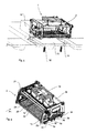
- FIG. 1 shows a device 1 according to the invention for forming stacks of Indeedgutzzusammen einen 10.
- the reference numeral 4 refers to a shifter, which is part of a feeder 5 and which pushes the piece goods compartments 10 in a transport device 2 into it.
- intermediate layers 13 are brought from below to this transport device 2.
- the transport device 2 is preferably rotatably arranged on an arm 7.
- This arm 7 is in turn arranged on a central rotatable frame 8.
- Another corresponding arm 7, on which a further transport device 2 is provided, is approaching on the right in FIG. 1 recognizable.
- FIG. 2 shows another view of the in FIG. 1
- a reservoir 11 for intermediate layers 13 can be seen.
- a cutting device (not shown) is preferably also provided, which cuts the individual intermediate layers, so that they can be guided under the transport device 2.
- the piece goods assemblies 10 are inserted from the side into the transport device 2.
- the transport device 2 has a lateral opening 2a.
- the transport device 2 itself is brought from above to the intermediate layers 13.
- the reservoir 11 is designed here as a frame, within which a strip of material 19 is arranged.
- This strip of material 19 is folded several times, wherein the reference numeral 21 shows a single fold. In this way, the material strip 19 can be stored in a very space-saving manner.
- the material strip 19 is at the in Fig. 2 embodiment shown pulled over the frame 11, so that an occurrence of tilting can be avoided.
- the back of the frame 11 acts here as a second reservoir for a second strip of material.
- the two strips of material 19 can alternatively be supplied to a pre-guide unit 17, so that it also bridges periods of time which arise when a strip of material 19 is used up and a new strip of material 19 has to be supplied.
- the pre-drive unit has here a circulating conveyor belt, which conveys the intermediate layers 13, which are separated in each case from the material strip 19, under the transport device 2.
- Figure 3 shows a plan view of a device according to the invention. It can be seen here that two arms 7 each having a transport device 2 are arranged on the frame 8. This frame 8 can be rotated to move the arms 7 with the transport means between a conveyor belt 80 and the pre-drive unit 17.
- the reference numeral 61 refers to a separator disposed between the reservoir 11 and the pre-lead unit 17.
- the strip of material (not shown) is transported in the direction of the transport path T to the feeding unit 17, and the separating device 61 cuts intermediate layers from the strip of material.
- the length of these intermediate layers in the direction T can be adjusted by the user.
- the strip of material is transported in cycles and the transport of the already cut intermediate layers is clocked on the pre-guide unit 17.
- a separation process or cutting process preferably takes place while the strip of material rests.
- Fig. 4 shows a representation of a separator 61.
- This separator 61 comprises a first roller unit 70 with two rollers 72, 74, between which the intermediate layer or the strip of material can be guided.
- the reference numeral 75 refers to a second roller unit, which also has two rollers 76, 77, between which the strip of material can be guided.
- the two lower rollers 74 and 77 preferably have the same outer diameter and preferably also the two upper rollers 72 and 76 have the same diameter.
- the diameters of all rolls are the same size. It is also possible that the rotations of the individual rollers 72, 74, 76, 77 are synchronized with each other.
- a cutting unit is arranged between the two roller units 70, 75, wherein this cutting unit has a carrier 65 and a cutting blade 62 arranged on this carrier 65, which is movable in the direction of the arrow P3.
- the reference numeral 66 refers to a cutting table over which the strip of material is laid to be cut.
- FIG. 5 shows a further illustration of a device according to the invention 1. it can be seen here that the intermediate layers 13 are temporarily stored on a table 14, before they are gripped by a transport device 2. This table 14 can be adjusted by means of height-adjustable feet 16 in height.
- FIG. 6 shows a transport device 2. This has two side parts 15, between which a support device 6 is arranged.
- This support device 6 has a plurality of rotatable bodies 12. For transporting a piece goods compilation or package layer is pushed laterally in the direction of the arrow P in the transport device 2 and during this process, the rotatable body 12, which are rollers, rotated. After the piece goods compilation is pushed into the transport device 2, the transport device can transport the piece goods compilation.
- a displaceable rod 28 is provided, which can align the Indeedgutzzusammengnagna in the interior of the transport device 2 in the direction of the arrow P1.
- the rod 28 can move in a rail along the arrow P1. While the piece goods compilation is introduced, the bar 28 is moved up to the side, so as not to hinder the insertion of the piece goods compilation.
- Reference numeral 26 refers to a shaft arranged between the two side parts 15. This shaft is rotated by a motor 24 and a gear 25. By means of this shaft 26 and two arranged on her gears 27 (only one gear is visible), the support means 6 can be moved over an open chain and thus free the area below the piece goods compilation. A corresponding shaft 26 is also on the in Fig. 6 rear side of the transport device 2 is provided.
- the transport device 2 can be arranged on a pivot arm.
- the device further comprises a rail, in which the support means 6 can be moved to the in FIG. 1 open by the support means 6 closed area.
- the reference numeral 34 refers to the above-mentioned coupling devices to provide the strip-shaped body or suction bars 20 with vacuum. In this case, these coupling devices 34 are designed so that they only in the in FIG. 1 shown closed state of the support a vacuum on the suction pads apply.
- the suction bars 20 are activated to suck in a below the conveyor 2 intermediate layer or record and then transport this intermediate layer together with the piece goods compilation 2.
- FIG. 7 shows a plan view from below of a transport device 2 according to the invention. It can be seen that here four strip-shaped body or suction bars 20 are incorporated into the support means 6. In this case, these strip-shaped body 20 are each arranged between rotatable bodies 12. Preferably, the strip-shaped body 20 are arranged with respect to the rotatable body, that in the upward direction of the strip-shaped body 20 does not come into contact with the Indeedgutzzusammen einen.
- the support device 6 is composed of two sub-sections 6a and 6b, which are formed substantially symmetrically relative to each other.
- the two sections 6a, 6b are pulled apart, so that between the two sections 6a, 6b, an opening 9 is released, through which the Indeedgutzzusammen ein can fall down.
- a total of four strip-shaped body 20 are provided on which in turn a plurality of fixing elements or suction elements 22 is provided.
- the louver head i.e., the conveyor 2
- the conveyor 2 directly under the loading surface.
- the reference numeral 34 also shows a coupling device to pressurize the strip-shaped body 20 and thus also the individual suction elements 22 with vacuum.
- the reference numeral 23 refers to sensor devices which detect the presence of intermediate layers. These may be, for example, touch sensors or light sensors.
- the individual suction elements 22 can be actuated separately.
- the suction elements 22 can also be acted upon by compressed air in order to be able to release the intermediate layers from them.
- FIG. 8 shows a side view of a transport device 2 according to the invention. It also recognizes support body 36, which serve as a transport lock to prevent damage, in particular of the coupling devices 34. After this has been done, the liners are replaced by the in FIG. 5 sucked suction.
- the reference numeral 40 refers to a vacuum distribution device, which the individual in FIG. 2 shown strip-shaped body 20 applied with vacuum. In addition, compressed air can also be output to the coupling devices 34 and thus the suction elements 22 via this vacuum distribution device 40.
- FIG. 9 shows a further side view of a transport device according to the invention.
- a further displacement device 38 which serves for the lateral alignment of the container assembly, can be seen here in particular.
- This further displacement device 38 is arranged on a carrier 39.
- Another (not shown) displacement device is provided on the opposite side of the transport device 2.
- the reference numeral 28 refers back to the rod, which prevents falling out of the container from the transport device 2.
- FIG. 10 illustrates the delivery of the vacuum to the strip-shaped bodies (not shown) FIG. 2 ,
- a total of four coupling devices are provided, which act on the strip-shaped body 20 with the vacuum.
- These coupling devices 34 are in the process FIG. 5 shown embodiment on a common carrier 41.
- This carrier 41 in turn is connected via connecting devices 54 on the side parts 15 of FIG FIG. 1 arranged transport device arranged.
- the coupling devices 34 have coupling heads 42, which are pivotable downwards.
- these coupling heads 42 are arranged on a Auslegearm 44, which in turn is arranged pivotably relative to a carrier 46.
- the reference numeral 48 refers to a connection with which, for example via a hose, the coupling head 42 can be subjected to vacuum. Also, air can be supplied via this hose (pressure).
- the reference numeral 40 also shows the Vakuumverteilinnate here, but not at the FIG. 8 is shown, but preferably below the carrier 41.
- This Vakuumverteil listening 40 has a plurality of outputs 52, to which the above-mentioned tubes for supplying the individual coupling heads 42 may be connected.
- a vacuum By applying the coupling heads 42 with a vacuum, as mentioned above, an intermediate layer can be tightened. In order to lower the intermediate layer, this vacuum is removed and preferably additionally compressed air is output. Subsequently, the support device 6 can be moved relative to the coupling heads 42. This makes it possible to keep the coupling heads 42 and the entire coupling device 34 stationary and thus less susceptible to wear.
- the reference numeral 56 refers to a filter, which is followed by a venturi 58 downstream.
- the vacuum distribution device 40 is supplied with compressed air via a connection 60.
Landscapes
- Engineering & Computer Science (AREA)
- Mechanical Engineering (AREA)
- De-Stacking Of Articles (AREA)
- Making Paper Articles (AREA)
Applications Claiming Priority (1)
| Application Number | Priority Date | Filing Date | Title |
|---|---|---|---|
| DE102008020486.2A DE102008020486B4 (de) | 2008-04-23 | 2008-04-23 | Vorrichtung und Verfahren zum Palettieren von Stückgutzusammenstellungen |
Publications (2)
| Publication Number | Publication Date |
|---|---|
| EP2112101A1 true EP2112101A1 (fr) | 2009-10-28 |
| EP2112101B1 EP2112101B1 (fr) | 2011-10-19 |
Family
ID=40827205
Family Applications (1)
| Application Number | Title | Priority Date | Filing Date |
|---|---|---|---|
| EP09156008A Ceased EP2112101B1 (fr) | 2008-04-23 | 2009-03-24 | Dispositif et procédé destinés à la palettisation d'assemblages de marchandises au détail |
Country Status (2)
| Country | Link |
|---|---|
| EP (1) | EP2112101B1 (fr) |
| DE (1) | DE102008020486B4 (fr) |
Cited By (4)
| Publication number | Priority date | Publication date | Assignee | Title |
|---|---|---|---|---|
| WO2013038102A1 (fr) | 2011-09-15 | 2013-03-21 | Sidel Participations | Dispositif de transfert de couches pré-conformées d'objets sur le dessus d'une palette. |
| EP2762428A1 (fr) * | 2013-02-04 | 2014-08-06 | Krones Aktiengesellschaft | Procédé et dispositif de palettisation de couches de produits, d'articles et/ou de récipients |
| CN104925533A (zh) * | 2015-06-09 | 2015-09-23 | 江苏新美星包装机械股份有限公司 | 码垛机中物料的码垛成型装置 |
| WO2021170403A1 (fr) * | 2020-02-25 | 2021-09-02 | Khs Gmbh | Appareil de palettisation et procédé d'empilement de paquets |
Families Citing this family (5)
| Publication number | Priority date | Publication date | Assignee | Title |
|---|---|---|---|---|
| DE102009058785B4 (de) * | 2009-12-18 | 2015-06-25 | Fraunhofer-Gesellschaft zur Förderung der angewandten Forschung e.V. | Vorrichtung zum Greifen von Objekten und Verfahren zum Greifen von Objekten |
| DE202010008173U1 (de) | 2010-04-28 | 2011-11-14 | Autefa Automation Gmbh | Handhabungseinrichtung |
| CN106477310B (zh) * | 2016-10-28 | 2019-07-05 | 江苏新美星液体包装工程技术研究中心有限公司 | 多通道式垛型的成型装置 |
| CN106429470A (zh) * | 2016-10-28 | 2017-02-22 | 江苏新美星液体包装工程技术研究中心有限公司 | 直线输送式垛型成型装置 |
| DE102019128026A1 (de) * | 2019-10-17 | 2021-04-22 | Krones Ag | Zentriereinrichtung, Verfahren zum Anpassen einer Zentriereinrichtung sowie Stapel- und/oder Palettiervorrichtung |
Citations (5)
| Publication number | Priority date | Publication date | Assignee | Title |
|---|---|---|---|---|
| DE2945883A1 (de) | 1979-11-14 | 1981-05-27 | Holstein Und Kappert Gmbh, 4600 Dortmund | Vorrichtung zum beladen von paletten mit stueckguetern |
| DE3627577A1 (de) * | 1986-08-14 | 1988-02-18 | Heinrich Langhammer | Palettenfuellstation |
| US4998399A (en) | 1989-02-06 | 1991-03-12 | Nigrelli Systems, Inc. | PET bottle packer |
| US5375493A (en) * | 1992-03-12 | 1994-12-27 | Focke & Co. (Gmbh & Co.) | Method and apparatus for feeding separator sheets to a stack |
| EP0893379A1 (fr) * | 1997-07-26 | 1999-01-27 | Heinrich Langhammer | Dispositif de palettisation |
Family Cites Families (8)
| Publication number | Priority date | Publication date | Assignee | Title |
|---|---|---|---|---|
| AT260672B (de) | 1963-06-12 | 1968-03-11 | Freiberg Papier Maschwerke | Verfahren und Vorrichtung zur Aufnahme, Bewegung und Ablage feuchter oder nasser Pappebogen |
| CH440130A (de) | 1966-02-07 | 1967-07-15 | Ferag Ag | Kreuzleger |
| DE3720933A1 (de) | 1987-06-25 | 1989-01-05 | Focke & Co | Verfahren und vorrichtung zum lagenweisen beladen von paletten |
| DE9202553U1 (de) | 1992-02-27 | 1992-04-30 | KHS Verpackungstechnik GmbH, 44143 Dortmund | Vorrichtung zum Auflösen und Bilden von Stückgutstapeln |
| DE4208490A1 (de) | 1992-03-17 | 1993-09-23 | Wirth Muehlenbau Dresden Gmbh | Verfahren und einrichtung zur aufrechterhaltung eines ueber die laenge der walzen konstanten walzenspaltes |
| DE19815434A1 (de) | 1998-04-07 | 1999-10-14 | Focke & Co | Hubvorrichtung (Palettierer) mit Schwenkarm |
| DK175297B1 (da) | 2002-10-02 | 2004-08-16 | Majgaard Invest Aps | Fremgangsmåde og maskine til uddispensering af palletteringsark |
| DE102006047554B4 (de) | 2006-10-07 | 2010-08-12 | Kuka Roboter Gmbh | Vorrichtung und Verfahren zum Umsetzen von Gebinden |
-
2008
- 2008-04-23 DE DE102008020486.2A patent/DE102008020486B4/de not_active Expired - Fee Related
-
2009
- 2009-03-24 EP EP09156008A patent/EP2112101B1/fr not_active Ceased
Patent Citations (5)
| Publication number | Priority date | Publication date | Assignee | Title |
|---|---|---|---|---|
| DE2945883A1 (de) | 1979-11-14 | 1981-05-27 | Holstein Und Kappert Gmbh, 4600 Dortmund | Vorrichtung zum beladen von paletten mit stueckguetern |
| DE3627577A1 (de) * | 1986-08-14 | 1988-02-18 | Heinrich Langhammer | Palettenfuellstation |
| US4998399A (en) | 1989-02-06 | 1991-03-12 | Nigrelli Systems, Inc. | PET bottle packer |
| US5375493A (en) * | 1992-03-12 | 1994-12-27 | Focke & Co. (Gmbh & Co.) | Method and apparatus for feeding separator sheets to a stack |
| EP0893379A1 (fr) * | 1997-07-26 | 1999-01-27 | Heinrich Langhammer | Dispositif de palettisation |
Cited By (11)
| Publication number | Priority date | Publication date | Assignee | Title |
|---|---|---|---|---|
| WO2013038102A1 (fr) | 2011-09-15 | 2013-03-21 | Sidel Participations | Dispositif de transfert de couches pré-conformées d'objets sur le dessus d'une palette. |
| FR2980183A1 (fr) * | 2011-09-15 | 2013-03-22 | Sidel Participations | Dispositif de transfert de couches pre-conformees d'objets sur le dessus d'une palette. |
| US9676568B2 (en) | 2011-09-15 | 2017-06-13 | Gebo Packaging Solutions Italy S.R.L. | Device for transferring pre-formed layers of objects to the top of a pallet |
| CN107055107A (zh) * | 2011-09-15 | 2017-08-18 | 意大利致博包装解决方案公司 | 用于将物件预成型层转移至托盘顶部的设备 |
| CN107089518A (zh) * | 2011-09-15 | 2017-08-25 | 意大利致博包装解决方案公司 | 用于将物件预成型层转移至托盘顶部的设备 |
| CN107055107B (zh) * | 2011-09-15 | 2020-08-18 | 意大利致博包装解决方案公司 | 用于将物件预成型层转移至托盘顶部的设备 |
| CN107089518B (zh) * | 2011-09-15 | 2021-01-22 | 意大利致博包装解决方案公司 | 用于将物件预成型层转移至托盘顶部的设备 |
| EP2762428A1 (fr) * | 2013-02-04 | 2014-08-06 | Krones Aktiengesellschaft | Procédé et dispositif de palettisation de couches de produits, d'articles et/ou de récipients |
| CN104925533A (zh) * | 2015-06-09 | 2015-09-23 | 江苏新美星包装机械股份有限公司 | 码垛机中物料的码垛成型装置 |
| WO2021170403A1 (fr) * | 2020-02-25 | 2021-09-02 | Khs Gmbh | Appareil de palettisation et procédé d'empilement de paquets |
| US11999578B2 (en) | 2020-02-25 | 2024-06-04 | Khs Gmbh | Palletizing apparatus and method for stacking packages |
Also Published As
| Publication number | Publication date |
|---|---|
| DE102008020486B4 (de) | 2018-08-09 |
| DE102008020486A1 (de) | 2009-10-29 |
| EP2112101B1 (fr) | 2011-10-19 |
Similar Documents
| Publication | Publication Date | Title |
|---|---|---|
| EP2112101B1 (fr) | Dispositif et procédé destinés à la palettisation d'assemblages de marchandises au détail | |
| EP2144830B1 (fr) | Procédé et dispositif pour emballer des grands emballages pour bouteilles | |
| EP0560112B1 (fr) | Dispositif pour amener des couches intercalaires à une pile | |
| AT13828U1 (de) | Kommissioniersystem und Verfahren zur Beladung von Ladungsträgern | |
| EP0706946B1 (fr) | Méthode et dispositif pour faire la manutention de piles de découpes avec banderole | |
| EP2258618B1 (fr) | Dispositif et procédé destinés à la fabrication d'une unité d'emballage | |
| EP1405809B1 (fr) | Dispositif pour former des colis de produits empilés | |
| DE102005002532A1 (de) | Vorrichtung und Verfahren zum automatisierten und zeitgleichen Bereitstellen und Wechseln von mindestens zwei Rollen aus Papierbahnen oder dergleichen für einen nachgeordneten Formatschneider | |
| EP2243732B1 (fr) | Dispositif et procédé destinés à transférer des gerbes ou des couches d'articles dans une station de chargement | |
| DE102016200581B4 (de) | Verfahren zur Zuförderung, Bereitstellung und zum Austausch von Rollen mit Verpackungsmaterial in einer Verpackungsmaschine | |
| EP1354797B1 (fr) | Machine pour emballer des articles plats dans des conteneurs, en particulier des boîtes pliées à plat, dans des cartons | |
| EP2782836B1 (fr) | Procédé et dispositif permettant de manipuler des sachets regroupés en paquets | |
| EP2119650B1 (fr) | Procédé et dispositif de palettisation de marchandises au détail | |
| WO2009121542A1 (fr) | Équipement et procédé de fabrication de sacs à partir de tronçons de tube souple | |
| AT506539B1 (de) | Fördervorrichtung mit einem aufnahmemittel für eine trennlage | |
| WO2015124750A2 (fr) | Dispositif et procédé de transbordement d'unités de chargement | |
| EP2653417A1 (fr) | Dispositif et procédé de dépôt d'une série de paquets formés à partir d'au moins un paquet sur une palette | |
| EP2243731A1 (fr) | Dispositif de palettisation d'articles par couches | |
| WO1997011899A1 (fr) | Dispositif pour transporter une couche de recipients en verre sur une palette | |
| EP2655197A1 (fr) | Procédé pour l'enlèvement d'une feuille à partir d'unités d'emballage et station d'enlèvement de feuilles | |
| EP2773580B1 (fr) | Dispositif de transport et de manutention de produits | |
| DE19519615A1 (de) | Vorrichtung für das Stapeln von Profilen | |
| EP1400452B1 (fr) | Procédé et dispositif d'emballage de pièces en forme de plaque | |
| DE102014223794A1 (de) | Verfahren zur Steuerung einer Faltschachtelklebemaschine mit einer nachfolgenden Vorrichtung zum Packen | |
| DE102009022249B4 (de) | Übergabevorrichtung zur Übergabe eines durch mehrere Blattlagen gebildeten Stapels |
Legal Events
| Date | Code | Title | Description |
|---|---|---|---|
| PUAI | Public reference made under article 153(3) epc to a published international application that has entered the european phase |
Free format text: ORIGINAL CODE: 0009012 |
|
| AK | Designated contracting states |
Kind code of ref document: A1 Designated state(s): AT BE BG CH CY CZ DE DK EE ES FI FR GB GR HR HU IE IS IT LI LT LU LV MC MK MT NL NO PL PT RO SE SI SK TR |
|
| AX | Request for extension of the european patent |
Extension state: AL BA RS |
|
| 17P | Request for examination filed |
Effective date: 20100303 |
|
| AKX | Designation fees paid |
Designated state(s): DE FR IT |
|
| GRAP | Despatch of communication of intention to grant a patent |
Free format text: ORIGINAL CODE: EPIDOSNIGR1 |
|
| GRAS | Grant fee paid |
Free format text: ORIGINAL CODE: EPIDOSNIGR3 |
|
| RIN1 | Information on inventor provided before grant (corrected) |
Inventor name: PERL, KURT |
|
| GRAA | (expected) grant |
Free format text: ORIGINAL CODE: 0009210 |
|
| AK | Designated contracting states |
Kind code of ref document: B1 Designated state(s): DE FR IT |
|
| REG | Reference to a national code |
Ref country code: DE Ref legal event code: R096 Ref document number: 502009001629 Country of ref document: DE Effective date: 20120119 |
|
| PLBE | No opposition filed within time limit |
Free format text: ORIGINAL CODE: 0009261 |
|
| STAA | Information on the status of an ep patent application or granted ep patent |
Free format text: STATUS: NO OPPOSITION FILED WITHIN TIME LIMIT |
|
| 26N | No opposition filed |
Effective date: 20120720 |
|
| REG | Reference to a national code |
Ref country code: DE Ref legal event code: R097 Ref document number: 502009001629 Country of ref document: DE Effective date: 20120720 |
|
| REG | Reference to a national code |
Ref country code: FR Ref legal event code: PLFP Year of fee payment: 8 |
|
| REG | Reference to a national code |
Ref country code: FR Ref legal event code: PLFP Year of fee payment: 9 |
|
| REG | Reference to a national code |
Ref country code: FR Ref legal event code: PLFP Year of fee payment: 10 |
|
| PGFP | Annual fee paid to national office [announced via postgrant information from national office to epo] |
Ref country code: DE Payment date: 20220203 Year of fee payment: 14 |
|
| PGFP | Annual fee paid to national office [announced via postgrant information from national office to epo] |
Ref country code: IT Payment date: 20220210 Year of fee payment: 14 Ref country code: FR Payment date: 20220209 Year of fee payment: 14 |
|
| REG | Reference to a national code |
Ref country code: DE Ref legal event code: R119 Ref document number: 502009001629 Country of ref document: DE |
|
| PG25 | Lapsed in a contracting state [announced via postgrant information from national office to epo] |
Ref country code: FR Free format text: LAPSE BECAUSE OF NON-PAYMENT OF DUE FEES Effective date: 20230331 Ref country code: DE Free format text: LAPSE BECAUSE OF NON-PAYMENT OF DUE FEES Effective date: 20231003 |
|
| PG25 | Lapsed in a contracting state [announced via postgrant information from national office to epo] |
Ref country code: IT Free format text: LAPSE BECAUSE OF NON-PAYMENT OF DUE FEES Effective date: 20230324 |