EP2111092A2 - Loading head, automatic loader, method for fetching construction elements and method for loading substrates - Google Patents
Loading head, automatic loader, method for fetching construction elements and method for loading substrates Download PDFInfo
- Publication number
- EP2111092A2 EP2111092A2 EP09154944A EP09154944A EP2111092A2 EP 2111092 A2 EP2111092 A2 EP 2111092A2 EP 09154944 A EP09154944 A EP 09154944A EP 09154944 A EP09154944 A EP 09154944A EP 2111092 A2 EP2111092 A2 EP 2111092A2
- Authority
- EP
- European Patent Office
- Prior art keywords
- pipette
- placement
- substrate
- pipettes
- placement head
- Prior art date
- Legal status (The legal status is an assumption and is not a legal conclusion. Google has not performed a legal analysis and makes no representation as to the accuracy of the status listed.)
- Granted
Links
- 239000000758 substrate Substances 0.000 title claims abstract description 106
- 238000000034 method Methods 0.000 title claims abstract description 17
- 238000010276 construction Methods 0.000 title description 3
- 239000000969 carrier Substances 0.000 claims abstract description 35
- 230000000717 retained effect Effects 0.000 claims 1
- 230000001133 acceleration Effects 0.000 description 2
- 230000001419 dependent effect Effects 0.000 description 1
- 230000008021 deposition Effects 0.000 description 1
- 238000005516 engineering process Methods 0.000 description 1
- 230000008092 positive effect Effects 0.000 description 1
Images


Classifications
-
- H—ELECTRICITY
- H05—ELECTRIC TECHNIQUES NOT OTHERWISE PROVIDED FOR
- H05K—PRINTED CIRCUITS; CASINGS OR CONSTRUCTIONAL DETAILS OF ELECTRIC APPARATUS; MANUFACTURE OF ASSEMBLAGES OF ELECTRICAL COMPONENTS
- H05K13/00—Apparatus or processes specially adapted for manufacturing or adjusting assemblages of electric components
- H05K13/04—Mounting of components, e.g. of leadless components
- H05K13/0404—Pick-and-place heads or apparatus, e.g. with jaws
- H05K13/0408—Incorporating a pick-up tool
- H05K13/041—Incorporating a pick-up tool having multiple pick-up tools
-
- H—ELECTRICITY
- H05—ELECTRIC TECHNIQUES NOT OTHERWISE PROVIDED FOR
- H05K—PRINTED CIRCUITS; CASINGS OR CONSTRUCTIONAL DETAILS OF ELECTRIC APPARATUS; MANUFACTURE OF ASSEMBLAGES OF ELECTRICAL COMPONENTS
- H05K13/00—Apparatus or processes specially adapted for manufacturing or adjusting assemblages of electric components
- H05K13/04—Mounting of components, e.g. of leadless components
- H05K13/0404—Pick-and-place heads or apparatus, e.g. with jaws
- H05K13/0413—Pick-and-place heads or apparatus, e.g. with jaws with orientation of the component while holding it; Drive mechanisms for gripping tools, e.g. lifting, lowering or turning of gripping tools
Definitions
- the invention relates to the field of automatic placement of substrates by means of placement machines, which have a placement head for temporarily holding components, so that when a corresponding movement of the placement head, the components can be picked up, transported and placed on a component carrier.
- the present invention relates in particular to a placement head for equipping substrates with components. Furthermore, the present invention relates to a placement, a method for picking up components and a method for loading substrates.
- substrates for example printed circuit boards
- placement machines are equipped with components of various types with the aid of so-called placement machines.
- the components are provided by means arranged on the placement feeders at defined collection positions.
- a placement head of the placement machine which can be moved by a positioning system picks up the components at the pick-up positions and transfers them to a placement area of the placement machine, where they are positioned on provided substrates.
- Substrates to be loaded are fed to the placement area via a transport device, and finished substrates are transported out of the placement area via this transport device.
- a placement machine is for example from the patent DE 10336609 B3 known.
- a placement head with a plurality of grippers which has a longitudinal or a transverse guide for a displaceable therein longitudinal or transverse slide, wherein one of the gripper on the longitudinal slide and the other gripper on the cross slide is fixed so that they are displaceable parallel to a substrate plane.
- the placement head according to the invention for equipping substrates with components for a placement machine has at least one first and one second pipette carrier, which are configured to receive pipettes, wherein at least the first pipette carrier has a plurality of pipettes for handling the components.
- the pipettes are arranged at their respective pipette carrier in a plane parallel to a plane of the substrate and displaceable relative to their respective pipette carrier along their respective axis in a z-direction perpendicular to the plane of the substrate and rotatable about that respective axis.
- At least the first pipette carrier is rotatable about an axis of rotation, which is oriented perpendicular to the plane of the substrate.
- placement of the placement of a positioning of the placement machine is arranged linearly movable, so that a fixed relative to the placement substrate at the same time held relative to the placement machine positioning at least stripwise equippable.
- strip-wise assembly is understood to mean that a strip of the substrate, ie a region having a width other than zero, can be equipped with the stationary substrate and fixed positioning system with the aid of the placement head according to the invention.
- the positioning system is either movable or designed as a fixed linear guide for the placement. Prerequisite for the strip-wise loading is merely that the positioning system rests during the assembly of the stiff with multiple components. Strip-wise loading is then carried out exclusively by the linear movement of the placement head on the positioning system and by the adjustment of individual pipettes or pipette carrier transversely to the direction of travel of the placement.
- the "strip-wise assembly" can be defined such that a plurality of components can be positioned at their placement positions within a strip of the substrate to be loaded, wherein the placement positions may have a different distance to a vertical projection of the travel axis of the placement on the substrate.
- the width of the strip is limited by the maximum operating radius of the pipettes.
- the axis of rotation is arranged eccentrically relative to the respective pipette carrier, so that the respective pipette carrier is pivotable in a plane parallel to the plane of the substrate.
- a swivel axis for the pipette carrier provides an easy way to move the pipettes arranged on the pipette carrier in a plane parallel to the plane of the substrate, without having to use linear axes or guides.
- off-center is understood to mean that the pivot axis, which is oriented perpendicular to the plane of the substrate, is arranged in a sectional plane parallel to the plane of the substrate either in an edge region of the pipette carrier or completely outside the outline of the pipette carrier.
- the pivot axis is by no means arranged at the intersection of the symmetry axes of the pipette carrier.
- At least one of the pipette carriers is linearly movable relative to the other pipette carrier at least in one direction parallel to the plane of the substrate at the placement head.
- the additional degree of freedom realized by the linear movement of one of the two pipette carriers enables independent positioning of two pipettes which are arranged on different pipette carriers. It is thereby possible to position at least two components held by the pipettes in a plane parallel to the plane of the substrate in such a way that they can be deposited simultaneously on their placement positions on the substrate by means of a feed movement in the z direction. As a result, the time proportion for the loading of the substrate can be significantly reduced, which in turn significantly increases the placement performance of the placement machine.
- each pipette carrier has a z-drive for moving at least one of the pipettes along their respective axis in the z-direction, wherein the z-drive thereby at least one any pipette of the respective pipette carrier can be coupled.
- the z-drive With the aid of the z-drive, it is possible to lower and / or raise a single pipette in a targeted manner in the z-direction perpendicular to the plane of the substrate.
- the z-drive can be coupled with the respective pipette.
- the mass accelerated in the z-direction is significantly reduced, which leads to an improved vibration behavior and thus to a higher placement accuracy.
- the lower moving mass higher accelerations are possible, which has a positive effect on the placement.
- each pipette of a pipette carrier is assigned its own, separately controllable z-drive, which allows a movement of the respective pipette in the z-direction.
- each pipette has its own, individually controllable z-drive, the axes of the individual pipettes can already be pre-positioned in the z-direction during the movement of the placement head.
- each pipette of a pipette carrier is associated with its own, separately controllable rotary drive, which allows a rotational movement of the respective pipette about their respective axis.
- each pipette is assigned its own, individually controllable rotary drive, can already during the movement of the placement or during the pre-positioning of the pipette in the z direction, a correction of the angular position of the held component about the respective z-axis of the Pipette.
- the placement can be further increased.
- At least the first pipette carrier has a plurality of pipettes, which are arranged in a straight line, so that the pipette carrier is pivotable in a plane parallel to the plane of the substrate by means of the eccentrically arranged axis of rotation.
- the axis of rotation is arranged eccentrically relative to the pipette carrier.
- the "action radius" of the individual pipettes can be increased around the axis of rotation, which allows greater flexibility in the relative positioning of multiple pipettes of different pipette carriers.
- the placement machine according to the invention for equipping substrates with components has a positioning system, which is arranged on a chassis of the placement and designed to accommodate at least one placement head, and a first placement head according to one of claims 1 to 9.
- the placement of the positioning system is designed as a fixed portal, which is firmly connected to the chassis, so that the placement is exclusively linearly movable by means of the positioning.
- the positioning system is designed as a fixed portal or guide element can be selected as a cost-effective implementation possibility.
- the positioning system is no longer movable relative to a machine base of the placement. All positioning movements within a strip of the substrate to be loaded are carried out by a linear movement of the placement head on the fixed positioning system and by movements of the pipettes and / or pipette carriers on the placement head. For equipping another Strip of the substrate is this cross, preferably orthogonal, proceeded to the direction of travel of the placement on the positioning system.
- a plurality of components can be positioned simultaneously on the substrate.
- the use of the placement head according to the invention allows a positioning of several pipettes relative to one another in a plane parallel to the plane of the substrate. This allows simultaneous deposition of several components on the substrate. The placement of the placement can be significantly increased.
- At least one further placement head is movably arranged on the positioning system.
- Each of the placement heads is assigned its own drive unit, which allow independent movement of the placement heads on the positioning system.
- a placement head which is designed according to one of claims 1 to 9 for a placement machine having feed means by which the components are provided at pickup positions
- pipettes of multiple pipette carriers are pre-positioned such that a plurality of components simultaneously by a feed movement of the respective pipettes in a z-direction perpendicular to a Level of the substrate to be picked up from their respective pickup positions.
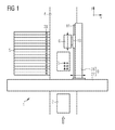
- FIG. 1 schematically shows the general structure of a placement machine 1 for equipping substrates 2 with components 3, which is suitable for receiving the placement head 6 according to the invention.
- the placement machine 1 has a cross member 27, which extends in a y-direction and fixed to a machine frame (not shown) is connected.
- a portal arm 28 is mounted, which extends in the x direction and is slidably mounted in the y direction on the cross member 27.
- Cross member 27 and portal arm 28 together form the positioning system 9, wherein an orthogonal reference frame is formed by the x-axis and the y-axis.
- a placement head 6 is mounted displaceably in the x direction, which can be moved defined by means of a drive unit 10 in the x direction along a arranged on the portal arm 28 guide member 11. Furthermore, a transport path 4 for transporting the substrates 2 in an assembly area of the placement machine 1 provided. Side of the transport path 4 are arranged in the vicinity of the placement area feeders 5, which provide the components 3 at their respective pick-up positions 26.
- the placement head 6 For loading a substrate 2, this is transported via the transport path 4 in the placement area.
- the electrical components 3 provided by the feed device 5 are picked up by the placement head 6 and transferred to the placement area, where they are positioned on the substrate 2 at their respective placement positions.
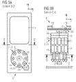
- FIGS. 2 to 4 show in each case only the first pipette support 7-1x concretely executed in all three embodiments, the second pipette support 7-2 is shown only schematically and can be configured arbitrarily. Since the first pipette carrier 7-1x in the FIGS. 2 to 4 is executed differently, the last digit of the respective reference refers to the respective figure. If the first pipette carrier is addressed in general, this is indicated by the placeholder x.
- the first pipette carrier 7-1x has a plurality of pipettes 8, which are arranged on the first pipette carrier 7-1x in an x / y plane.
- the x / y plane is parallel to a substrate plane, which is determined by the surface of the substrate 2 to be equipped, on which the components 3 are deposited.
- the individual pipettes 8 are displaceable along a z-direction perpendicular to the substrate plane and rotatable about their respective pipette axis 18, so that components 3 held by the pipettes can be positioned with regard to their angular position and can be deposited on the substrate 2.
- each pipette 8 is assigned its own z-drive 15 and its own rotary drive 14.
- first pipette carrier 7-1x also has an axis of rotation 12, which is likewise oriented in the z-direction perpendicular to the substrate plane.
- first pipette carrier 7-1x with the pipettes arranged thereon can be rotated or pivoted in a plane parallel to the plane of the substrate 2.
- FIGS. 2a and 2b show a first embodiment of the placement head 6, wherein FIG. 2a a sectional view taken along the line BB, and FIG. 2b show a sectional view along the line AA.
- the first pipette carrier 7-12 is designed to rotate horizontally and has a stator 16 and a rotor 13 on which the individual pipettes 8 are arranged. While the stator 16 is fixedly arranged on the placement head 6, the rotor 13 is rotatably mounted about an axis of rotation 12. Thus, the pipettes 8 can be moved in a plane parallel to the substrate plane.
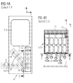
- FIGS. 3a and 3b show a second embodiment of the placement head 6, wherein FIG. 3a a sectional view taken along the line DD, and FIG. 3b a sectional view along the line CC show.
- the first pipette carrier 7-13 is in turn designed to rotate horizontally and accordingly also has a stator 16 and a rotor 13 rotating about the stator, on which the pipettes 8 are arranged.
- the rotation axis 12 is arranged off-center, so that the first pipette carrier 7-13 pivots about this axis of rotation 12 by means of a pivoting arm 23 can be.
- FIGS. 4a and 4b show a third embodiment of the placement head 6, wherein FIG. 4a a sectional view taken along the line FF, and FIG. 4b show a sectional view along the line EE.
- the individual pipettes 8 of the first pipette carrier 7-14 are arranged in a straight line in a row.
- the first pipette carrier 7-14 itself is rotatable about the axis of rotation 12, so that the individual pipettes 8 can be moved in the x / y plane, parallel to the substrate plane.
- the first pipette carrier is 7-14 in FIG. 4a still shown in two other possible positions, resulting from a rotation about the axis of rotation 12, shown in dashed lines.
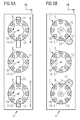
- FIGS. 5a to 5c show further embodiments of the placement head 6 according to the invention, which have more than two pipette carriers 7.
- FIG. 5a shows a placement head 6 with three horizontally rotating pipette carriers 7, which in terms of their construction from that of the FIGS. 2a and 2b correspond to known first pipette carrier 7-12. All three pipette carriers 7 have a rotatable about a rotation axis 12 rotor 13, on which the individual pipettes 8 are arranged. The individual pipettes 8 are displaceable along a z-direction perpendicular to the x / y-plane and rotatable about their respective pipette axis 18. For this purpose, each pipette 8 is assigned its own rotary drive 14 and its own z-drive 15.
- the middle pipette carrier 7 is arranged stationarily on the placement head 6, the two outer pipette carriers 7 are along one Linear guide 22 relative to the placement head 6 slidably.
- This additional degree of freedom enables independent positioning of two pipettes which are arranged on different pipette carriers. While the relative positioning of the two pipettes 8 in the y-direction is achieved by a rotational movement of the respective pipette carrier 7, the positioning in the x-direction is effected by a corresponding movement of the respective pipette carrier 7 along the respective linear guide 22.
- components 3, whose Placement positions are arranged on the substrate 2 immediately adjacent to each other, simultaneously or immediately successively deposited on the substrate 2, without the need for this, the entire placement head 6 must be moved in the meantime.
- FIG. 5b shows a further embodiment of the placement head 6 according to the invention also with three horizontally rotating pipette carriers 7. While the middle pipette carrier 7 is in turn fixedly mounted on the placement head 6, the two outer pipette carrier 7 correspond in terms of their construction from that of the FIGS. 3a and 3b known first pipette support 7-13. Both have an eccentrically arranged axis of rotation 12 about which the respective pipette carrier 7 can be pivoted. Since a relative movement of the individual pipette carriers 7 relative to one another can also be realized by the pivoting movement, there is no additional linear guide 22 for this embodiment, as in FIG FIG. 5a shown embodiment required.
- FIG. 5c shows a third embodiment of the placement head 6 according to the invention with also three pipette carriers 7, the pipettes 8 are each arranged in a straight line in a row.
- the three pipette carriers 7 are identical and correspond to that of the FIGS. 4a and 4b known first pipette support 7-14.
- the pipette carriers 7 are each arranged around their arranged in the edge region of the respective pipette carrier and oriented in the z direction Rotation axis 12 rotatable so that the individual pipettes 8 of the respective pipette carrier 7 in the x / y-plane, parallel to the substrate plane, can be moved.
- each of the pipette carriers 7 is shown in dashed lines in two further possible positions resulting from a rotation about the rotation axis 12 by 45 ° or 90 °. If, in addition, the pitch of the pipettes 8 arranged on the respective pipette carrier 7 corresponds to the pitch of the pick-up positions 26 of the feed devices 5 (see FIG FIG.
- FIGS. 6a and 6b each show a sectional view of the placement machine according to the invention (1) in a plan view, wherein the cutting plane below the positioning system 9 (see FIG. 1 ) was placed so that the placement heads 6 are not obscured by the positioning system 9.
- the positioning system 9 can be designed as a fixed portal, which is firmly connected to a chassis 17 of the placement machine 1, so that the two placement heads 6 are arranged movable only in the x-direction on the portal.
- the two placement heads 6 are thereby guided hanging on the positioning system 9.
- the placement machine 1 further has a transport path 4 for transporting substrates 2 in a y-direction. Furthermore, the placement machine 1 feeders 5, by means of which the components 3 at defined collection positions 26 are provided for pickup by a placement head 6.
- the two in the FIGS. 6a and 6b Placement machines 1 shown differ only in the embodiment of the assembled placement heads. 6
- FIG. 6a the placement machine 1 is equipped with two identical placement heads 6, as they are already out FIG. 5b are known.
- the two placement heads 6 are arranged in mirror image relative to one another on a common positioning system 9 (not shown) so as to be linearly displaceable in the x-direction.
- Both placement heads 6 each have three pipette carriers 7, of which in each case the two outer pivots are arranged on the placement head 6. This makes it possible to equip a significantly wider strip S of the substrate 2 in strips, ie exclusively by positioning movements of the placement head 6, without having to move the positioning system 9 or the substrate 2.
- Placement machine 1 shown is equipped with two different placement heads 6.
- One of the two placement heads 6 has three horizontally rotating pipette carrier 7 and is already from the description FIG. 5a known.
- the other placement head 6 has three pivotable pipette carriers 7, the pipettes 8 are each arranged in a straight line in a row, and is already out of the description to FIG. 5c known. Even with this configuration, it is possible to handle a plurality of components 3 at the same time or to equip a substrate 2 in strips.
- the pipettes 8 of a plurality of pipette carriers 7 are initially prepositioned such that their relative position to one another corresponds to the relative position of the corresponding placement positions on the substrate 2, whereby again only the degrees of freedom of the placement head 6 are utilized , The relative position of the positioning system 9 to the substrate 2 remains unchanged. Subsequently, a plurality of components are simultaneously deposited on their respective placement positions on the substrate 2 by a simultaneous feed movement of the prepositioned pipettes 8 in the z-direction.
- the positioning system 9 can be moved in the y-direction (if it is correspondingly movable) or-if the positioning system 9 is designed as a fixed portal-the substrate 2 is moved along the transport path 4 further transported by a strip width in the y direction.
Abstract
Description
Die Erfindung betrifft das Gebiet der automatischen Bestückung von Substraten mittels Bestückautomaten, welche einen Bestückkopf zum temporären Halten von Bauelementen aufweisen, so dass bei einer entsprechenden Bewegung des Bestückkopfes die Bauelemente aufgenommen, transportiert und auf einem Bauelementeträger aufgesetzt werden können. Die vorliegende Erfindung betrifft insbesondere einen Bestückkopf zum Bestücken von Substraten mit Bauelementen. Ferner betrifft die vorliegende Erfindung einen Bestückautomaten, ein Verfahren zum Abholen von Bauelementen sowie ein Verfahren zum Bestücken von Substraten.The invention relates to the field of automatic placement of substrates by means of placement machines, which have a placement head for temporarily holding components, so that when a corresponding movement of the placement head, the components can be picked up, transported and placed on a component carrier. The present invention relates in particular to a placement head for equipping substrates with components. Furthermore, the present invention relates to a placement, a method for picking up components and a method for loading substrates.
In der Bestücktechnik werden Substrate, beispielsweise Leiterplatten, mit Hilfe sogenannter Bestückautomaten mit Bauelementen verschiedenster Art bestückt. Hierzu werden die Bauelemente durch am Bestückautomaten angeordnete Zuführeinrichtungen an definierten Abholpositionen bereitgestellt. Ein durch ein Positioniersystem verfahrbarer Bestückkopf des Bestückautomaten holt die Bauelemente an den Abholpositionen ab und transferiert sie zu einem Bestückbereich des Bestückautomaten, wo sie auf bereitgestellten Substraten positioniert werden. Zu bestückende Substrate werden über eine Transporteinrichtung dem Bestückbereich zugeführt, fertig bestückte Substrate werden über diese Transporteinrichtung wieder aus dem Bestückbereich heraustransportiert. Ein derartiger Bestückautomat ist beispielsweise aus der Patentschrift
Ferner ist aus der Patentschrift
Es ist die Aufgabe der vorliegenden Erfindung, einen Bestückkopf, einen Bestückautomaten, sowie Verfahren zum Abholen von Bauelementen bzw. zum Bestücken von Substraten bereitzustellen, mittels derer die Bestückleistung erhöht werden kann.It is the object of the present invention to provide a placement head, a placement machine, as well as methods for picking up components or for loading of substrates, by means of which the placement performance can be increased.
Diese Aufgabe wird durch den Bestückkopf, den Bestückautomaten sowie das Verfahren zum Abholen von Bauelementen bzw. zum Bestücken von Substraten gemäß den unabhängigen Ansprüchen gelöst. Vorteilhafte Ausgestaltungen sind Gegenstand der abhängigen Ansprüche.This object is achieved by the placement head, the placement and the method for picking up components or for mounting substrates according to the independent claims. Advantageous embodiments are the subject of the dependent claims.
Der erfindungsgemäße Bestückkopf zum Bestücken von Substraten mit Bauelementen für einen Bestückautomaten weist mindestens einen ersten und einen zweiten Pipettenträger auf, welche zum Aufnehmen von Pipetten ausgestaltet sind, wobei zumindest der erste Pipettenträger mehrere Pipetten zum Handhaben der Bauelemente aufweist. Die Pipetten sind an ihrem jeweiligen Pipettenträger in einer Ebene parallel zu einer Ebene des Substrats angeordnet und relativ zu ihrem jeweiligen Pipettenträger entlang ihrer jeweiligen Achse in einer z-Richtung senkrecht zur Ebene des Substrats verschiebbar sowie um diese jeweilige Achse drehbar. Zumindest der erste Pipettenträger ist dabei um eine Drehachse, welche senkrecht zur Ebene des Substrats orientiert ist, drehbar.The placement head according to the invention for equipping substrates with components for a placement machine has at least one first and one second pipette carrier, which are configured to receive pipettes, wherein at least the first pipette carrier has a plurality of pipettes for handling the components. The pipettes are arranged at their respective pipette carrier in a plane parallel to a plane of the substrate and displaceable relative to their respective pipette carrier along their respective axis in a z-direction perpendicular to the plane of the substrate and rotatable about that respective axis. At least the first pipette carrier is rotatable about an axis of rotation, which is oriented perpendicular to the plane of the substrate.
Mit Hilfe eines derart gestalteten Bestückkopfs ist es möglich, zumindest eine Pipette relativ zum Bestückkopf in einer Ebene parallel zur Ebene des Substrats zu bewegen und auf diese Weise zumindest zwei Pipetten, welche an verschiedenen Pipettenträgern angeordnet sind, relativ zueinander zu positionieren. Damit ist es möglich, mehrere Bauelemente gleichzeitig zu handhaben, beispielsweise von ihren Abholpositionen abzuholen. Die Bauelemente werden mit Hilfe sogenannter Zuführeinrichtungen des Bestückautomaten an definierten Abholpositionen bereitgestellt. Durch eine Überlagerung mit der Verfahrbewegung des Bestückkopfs mit der Positionierbewegung zweier Pipetten relativ zueinander ist es somit möglich, mittels einer Zustellbewegung in z-Richtung, senkrecht zur Ebene des Substrats, mindestens zwei Bauelemente gleichzeitig von ihren Abholpositionen abzuholen. Hierbei ist zu beachten, dass der Teilungsabstand der Abholpositionen dem Abstand derjenigen Pipetten entspricht, welche die Bauelemente aufnehmen sollen. Der Zeitanteil für das Aufnehmen der Bauelemente kann dadurch deutlich verkürzt werden, was eine höhere Bestückleistung des Bestückautomaten ermöglicht.With the aid of a fitting head designed in this way, it is possible to move at least one pipette relative to the placement head in a plane parallel to the plane of the substrate and in this way to position at least two pipettes, which are arranged on different pipette carriers, relative to one another. This makes it possible to handle several components at the same time, for example, pick up from their pickup positions. The components are using so-called feeders of the placement at defined pick-up positions provided. By overlaying the movement of the placement head with the positioning movement of two pipettes relative to one another, it is thus possible to pick up at least two components from their pickup positions simultaneously by means of a feed movement in the z-direction, perpendicular to the plane of the substrate. It should be noted that the pitch of the pickup positions corresponds to the distance of those pipettes, which should receive the components. The time fraction for the recording of the components can be significantly reduced, which allows a higher placement performance of the placement.
In einer vorteilhaften Ausgestaltung des Bestückkopfs ist der Bestückkopf an einem Positioniersystem des Bestückautomaten linear verfahrbar angeordnet, so dass ein relativ zum Bestückautomaten feststehendes Substrat bei gleichzeitig relativ zum Bestückautomaten festgehaltenem Positioniersystem zumindest streifenweise bestückbar ist.In an advantageous embodiment of the placement of the placement of a positioning of the placement machine is arranged linearly movable, so that a fixed relative to the placement substrate at the same time held relative to the placement machine positioning at least stripwise equippable.
Unter der "streifenweisen Bestückung" ist dabei zu verstehen, dass ein Streifen des Substrats, d.h. ein Bereich mit einer von Null verschiedenen Breite, bei ruhendem Substrat und festgehaltenem Positioniersystem mit Hilfe des erfindungsgemäßen Bestückkopfs bestückt werden kann. Daraus ergibt sich der Vorteil, dass die Positionierung der einzelnen Bauelemente innerhalb eines Streifens des Substrats ausschließlich durch Positionierbewegungen des Bestückkopfs erfolgen kann - weder das Substrat noch das Positioniersystem selbst müssen dabei bewegt werden. Demnach muss nicht jede Bestückposition auf dem Substrat mittels einer Relativbewegung zwischen dem Positioniersystem und dem Substrat einzeln angesteuert werden. Vielmehr ist es ausreichend, das Positioniersystem sowie das Substrat derart relativ zueinander zu positionieren, dass allein durch die Positionierbewegungen des Bestückkopfs mehrere Bestückpositionen auf dem Substrat mit Bauelementen bestückbar sind. Indem Verfahrbewegungen des Positioniersystems vermieden werden und lediglich der Bestückkopf (und damit eine deutlich geringere Masse) bewegt wird, lassen sich Schwingungen, welche aus der Beschleunigung des Positioniersystems resultieren, deutlich reduzieren. Die Bestückgenauigkeit wird dadurch deutlich verbessert.The term "strip-wise assembly" is understood to mean that a strip of the substrate, ie a region having a width other than zero, can be equipped with the stationary substrate and fixed positioning system with the aid of the placement head according to the invention. This results in the advantage that the positioning of the individual components within a strip of the substrate can be effected exclusively by positioning movements of the placement head - neither the substrate nor the positioning system itself must be moved. Accordingly, it is not necessary to individually control each placement position on the substrate by means of a relative movement between the positioning system and the substrate. Rather, it is sufficient to position the positioning system and the substrate relative to one another such that a plurality of placement positions on the substrate can be equipped with components solely by the positioning movements of the placement head. By avoiding movements of the positioning system and only the placement head (and thus a significantly lower mass) is moved, can significantly reduce vibrations resulting from the acceleration of the positioning. The placement accuracy is significantly improved.
Das Positioniersystem ist dabei entweder verfahrbar oder auch als feststehende Linearführung für den Bestückkopf ausgebildet. Voraussetzung für das streifenweise Bestücken ist lediglich, dass das Positioniersystem während des Bestückens des Steifens mit mehreren Bauelementen ruht. Das streifenweise Bestücken erfolgt dann ausschließlich durch die lineare Verfahrbewegung des Bestückkopfs am Positioniersystem sowie durch die Verstellmöglichkeiten einzelner Pipetten oder Pipettenträger quer zur Verfahrrichtung des Bestückkopfs.The positioning system is either movable or designed as a fixed linear guide for the placement. Prerequisite for the strip-wise loading is merely that the positioning system rests during the assembly of the stiff with multiple components. Strip-wise loading is then carried out exclusively by the linear movement of the placement head on the positioning system and by the adjustment of individual pipettes or pipette carrier transversely to the direction of travel of the placement.
Gegenüber einer herkömmlichen Split-Axes Bestückung, bei denen unter anderem das Substrat für die Positionierung eines jeden Bauelements verfahren werden muss, resultiert hieraus der Vorteil, dass beim Bestücken eines Streifens das Substrat ruht, so dass bereits bestückte Bauelemente nicht durch die Verfahrbewegungen des Substrats verrutschen können.Compared with a conventional split-axis assembly, in which, inter alia, the substrate for the positioning of each component must be moved, this results in the advantage that the substrate rests when populating a strip, so that already assembled components do not slip through the movements of the substrate can.
Geometrisch betrachtet kann die "streifenweise Bestückung" derart definiert werden, dass mehrere Bauelemente auf ihre Bestückpositionen innerhalb eines zu bestückenden Streifens des Substrats positioniert werden können, wobei die Bestückpositionen einen unterschiedlichen Abstand zu einer senkrechten Projektion der Verfahrachse des Bestückkopfs auf das Substrat aufweisen dürfen. Die Breite des Streifens ist dabei durch den maximalen Aktionsradius der Pipetten begrenzt.Viewed geometrically, the "strip-wise assembly" can be defined such that a plurality of components can be positioned at their placement positions within a strip of the substrate to be loaded, wherein the placement positions may have a different distance to a vertical projection of the travel axis of the placement on the substrate. The width of the strip is limited by the maximum operating radius of the pipettes.
In einer weiteren vorteilhaften Ausgestaltung des Bestückkopfs ist die Drehachse relativ zum jeweiligen Pipettenträger außermittig angeordnet, so dass der jeweilige Pipettenträger in einer Ebene parallel zur Ebene des Substrats schwenkbar ist.In a further advantageous embodiment of the placement head, the axis of rotation is arranged eccentrically relative to the respective pipette carrier, so that the respective pipette carrier is pivotable in a plane parallel to the plane of the substrate.
Eine Schwenkachse für den Pipettenträger stellt eine einfache Möglichkeit dar, die am Pipettenträger angeordneten Pipetten in einer Ebene parallel zur Ebene des Substrats zu bewegen, ohne dabei Linearachsen oder -führungen verwenden zu müssen.A swivel axis for the pipette carrier provides an easy way to move the pipettes arranged on the pipette carrier in a plane parallel to the plane of the substrate, without having to use linear axes or guides.
Unter dem Begriff außermittig ist dabei zu verstehen, dass die Schwenkachse, welche senkrecht zur Ebene des Substrats orientiert ist, in einer Schnittebene parallel zur Ebene des Substrats entweder in einem Randbereich des Pipettenträgers oder vollständig außerhalb des Umrisses des Pipettenträgers angeordnet ist. Im Falle eines rotationssymmetrischen Pipettenträgers ist die Schwenkachse keinesfalls im Schnittpunkt der Symmetrieachsen des Pipettenträgers angeordnet.The term off-center is understood to mean that the pivot axis, which is oriented perpendicular to the plane of the substrate, is arranged in a sectional plane parallel to the plane of the substrate either in an edge region of the pipette carrier or completely outside the outline of the pipette carrier. In the case of a rotationally symmetrical pipette carrier, the pivot axis is by no means arranged at the intersection of the symmetry axes of the pipette carrier.
In einer weiteren vorteilhaften Ausgestaltung des Bestückkopfs ist zumindest einer der Pipettenträger zumindest in einer Richtung parallel zur Ebene des Substrats am Bestückkopf relativ zum anderen Pipettenträger linear verfahrbar.In a further advantageous embodiment of the placement head, at least one of the pipette carriers is linearly movable relative to the other pipette carrier at least in one direction parallel to the plane of the substrate at the placement head.
Der durch die Linearbewegung eines der beiden Pipettenträger realisierte, zusätzliche Freiheitsgrad ermöglicht eine unabhängige Positionierung zweier Pipetten, welche an verschiedenen Pipettenträgern angeordnet sind. Damit ist es möglich, zumindest zwei von den Pipetten gehaltene Bauelemente derart in einer Ebene parallel zur Ebene des Substrats zu positionieren, dass sie mittels einer Zustellbewegung in z-Richtung gleichzeitig auf ihre Bestückpositionen auf dem Substrat abgesetzt werden können. Dadurch kann der Zeitanteil für das Bestücken des Substrats deutlich reduziert werden, was wiederum die Bestückleistung des Bestückautomaten deutlich erhöht.The additional degree of freedom realized by the linear movement of one of the two pipette carriers enables independent positioning of two pipettes which are arranged on different pipette carriers. It is thereby possible to position at least two components held by the pipettes in a plane parallel to the plane of the substrate in such a way that they can be deposited simultaneously on their placement positions on the substrate by means of a feed movement in the z direction. As a result, the time proportion for the loading of the substrate can be significantly reduced, which in turn significantly increases the placement performance of the placement machine.
In einer weiteren vorteilhaften Ausgestaltung des Bestückkopfs weist jeder Pipettenträger einen z-Antrieb zum Bewegen zumindest einer der Pipetten entlang ihrer jeweiligen Achse in z-Richtung auf, wobei der z-Antrieb dabei an zumindest eine beliebige Pipette des jeweiligen Pipettenträgers ankoppelbar ist.In a further advantageous embodiment of the placement head, each pipette carrier has a z-drive for moving at least one of the pipettes along their respective axis in the z-direction, wherein the z-drive thereby at least one any pipette of the respective pipette carrier can be coupled.
Mit Hilfe des z-Antriebs ist es möglich, eine einzelne Pipette gezielt in z-Richtung senkrecht zur Ebene des Substrats abzusenken und/oder anzuheben. Der z-Antrieb kann dazu mit der jeweiligen Pipette gekoppelt werden. Dadurch wird die in z-Richtung beschleunigte Masse deutlich reduziert, was zu einem verbesserten Schwingungsverhalten und damit zu einer höheren Bestückgenauigkeit führt. Ferner sind durch die geringere bewegte Masse höhere Beschleunigungen möglich, was sich positiv auf die Bestückleistung auswirkt.With the aid of the z-drive, it is possible to lower and / or raise a single pipette in a targeted manner in the z-direction perpendicular to the plane of the substrate. The z-drive can be coupled with the respective pipette. As a result, the mass accelerated in the z-direction is significantly reduced, which leads to an improved vibration behavior and thus to a higher placement accuracy. Furthermore, the lower moving mass higher accelerations are possible, which has a positive effect on the placement.
In einer weiteren vorteilhaften Ausgestaltung des Bestückkopfs ist jeder Pipette eines Pipettenträgers ein eigener, separat ansteuerbarer z-Antrieb zugeordnet, welcher eine Bewegung der jeweiligen Pipette in z-Richtung ermöglicht.In a further advantageous embodiment of the placement head, each pipette of a pipette carrier is assigned its own, separately controllable z-drive, which allows a movement of the respective pipette in the z-direction.
Indem jede Pipette einen eigenen, individuell ansteuerbaren z-Antrieb aufweist, können die Achsen der einzelnen Pipetten während der Verfahrbewegung des Bestückkopfs bereits in z-Richtung vorpositioniert werden. Durch diese Parallelisierung der Verfahrbewegung des Bestückkopfs einerseits mit der Zustellbewegung der Pipetten in z-Richtung andererseits kann die Bestückleistung weiter erhöht werden.Since each pipette has its own, individually controllable z-drive, the axes of the individual pipettes can already be pre-positioned in the z-direction during the movement of the placement head. By this parallelization of the movement of the placement on the one hand with the feed movement of the pipettes in the z-direction on the other hand, the placement can be further increased.
In einer weiteren vorteilhaften Ausgestaltung des Bestückkopfs ist jeder Pipette eines Pipettenträgers ein eigener, separat ansteuerbarer Drehantrieb zugeordnet, welcher eine Drehbewegung der jeweiligen Pipette um ihre jeweilige Achse ermöglicht.In a further advantageous embodiment of the placement head each pipette of a pipette carrier is associated with its own, separately controllable rotary drive, which allows a rotational movement of the respective pipette about their respective axis.
Indem jeder Pipette ein eigener, individuell ansteuerbarer Drehantrieb zugeordnet ist, kann bereits während der Verfahrbewegung des Bestückkopfs oder auch während der Vorpositionierung der Pipette in z-Richtung eine Korrektur der Winkellage des gehaltenen Bauelements um die jeweilige z-Achse der Pipette erfolgen. Die Bestückleistung kann dadurch weiter erhöht werden.By each pipette is assigned its own, individually controllable rotary drive, can already during the movement of the placement or during the pre-positioning of the pipette in the z direction, a correction of the angular position of the held component about the respective z-axis of the Pipette. The placement can be further increased.
In einer weiteren vorteilhaften Ausgestaltung des Bestückkopfs weist zumindest der erste Pipettenträger einen Stator sowie einen um die Drehachse drehbaren Rotor auf, an dem die mindestens zwei Pipetten angeordnet sind.In a further advantageous embodiment of the placement head, at least the first pipette carrier on a stator and a rotatable about the axis of rotation rotor on which the at least two pipettes are arranged.
Mit Hilfe eines derartigen, horizontal drehenden Pipettenträgers mit einem um die senkrecht zur Substratebene orientierte Drehachse drehbaren Rotor, können die an dem Pipettenträger in z-Richtung verschiebbar angeordneten Pipetten in einer Ebene parallel zur Ebene des Substrats relativ zum Bestückkopf bewegt und damit relativ zu einer Pipette des anderen Pipettenträgers positioniert werden. Durch eine Überlagerung dieser Bewegung mit der Verfahrbewegung des Bestückkopfs ist es möglich, zumindest zwei Pipetten derart zu positionieren, dass mehrere Bauelemente gleichzeitig von ihren Abholpositionen abgeholt oder auf dem Substrat abgesetzt werden können. Ferner ist es möglich, die Pipetten innerhalb eines Streifens über dem Substrat derart zu positionieren, dass das Substrat streifenweise bestückt werden kann. Die Breite des Streifens entspricht dabei der doppelten Breite des Abstands der Halteeinrichtungen zur Drehachse des Rotors.With the aid of such a horizontally rotating pipette carrier with a rotatable around the axis perpendicular to the substrate plane rotation axis rotatable on the pipette carrier in the z direction arranged pipettes in a plane parallel to the plane of the substrate moves relative to the placement and thus relative to a pipette of the other pipette carrier. By superimposing this movement with the travel movement of the placement head, it is possible to position at least two pipettes in such a way that a plurality of components can be picked up at the same time from their pickup positions or deposited on the substrate. Furthermore, it is possible to position the pipettes within a strip over the substrate in such a way that the substrate can be equipped in strips. The width of the strip corresponds to twice the width of the distance of the holding devices to the axis of rotation of the rotor.
In einer weiteren vorteilhaften Ausgestaltung des Bestückkopfs weist zumindest der erste Pipettenträger mehrere Pipetten auf, welche in einer Reihe geradlinig angeordnet sind, so dass der Pipettenträger mittels der außermittig angeordneten Drehachse in einer Ebene parallel zur Ebene des Substrats schwenkbar ist.In a further advantageous embodiment of the placement head, at least the first pipette carrier has a plurality of pipettes, which are arranged in a straight line, so that the pipette carrier is pivotable in a plane parallel to the plane of the substrate by means of the eccentrically arranged axis of rotation.
Auch durch das Schwenken eines Pipettenträgers, bei dem mehrere Pipetten in einer Reihe angeordnet sind, um die Drehachse, welche senkrecht zur Ebene des Substrats orientiert ist, ist es möglich, die am Pipettenträger angeordneten Pipetten in einer Ebene parallel zur Ebene des Substrats zu bewegen.Also, by pivoting a pipette carrier in which a plurality of pipettes are arranged in a row about the axis of rotation which is oriented perpendicular to the plane of the substrate, it is possible to move the pipettes arranged on the pipette carrier in a plane parallel to the plane of the substrate.
Vorteilhafter Weise ist die Drehachse dabei relativ zum Pipettenträger außermittig angeordnet. Hierdurch kann der "Aktionsradius" der einzelnen Pipetten um die Drehachse vergrößert werden, was eine höhere Flexibilität bei der relativen Positionierung mehrerer Pipetten verschiedener Pipettenträger erlaubt. Hinsichtlich der weiteren Vorteile wird auf die obigen Ausführungen zum horizontal drehenden Pipettenträger verwiesen.Advantageously, the axis of rotation is arranged eccentrically relative to the pipette carrier. In this way, the "action radius" of the individual pipettes can be increased around the axis of rotation, which allows greater flexibility in the relative positioning of multiple pipettes of different pipette carriers. With regard to the further advantages, reference is made to the above statements on the horizontally rotating pipette carrier.
Der erfindungsgemäße Bestückautomat zum Bestücken von Substraten mit Bauelementen weist ein Positioniersystem, das an einem Chassis des Bestückautomaten angeordnet und zum Aufnehmen zumindest eines Bestückkopfs ausgebildet ist, sowie einen ersten Bestückkopf nach einem der Ansprüche 1 bis 9 auf.The placement machine according to the invention for equipping substrates with components has a positioning system, which is arranged on a chassis of the placement and designed to accommodate at least one placement head, and a first placement head according to one of
Hinsichtlich der Vorteile eines derartigen Bestückautomaten wird auf die obigen Ausführungen zu den Vorteilen des erfindungsgemäßen Bestückkopfs verwiesen.With regard to the advantages of such placement machines, reference is made to the above statements on the advantages of the placement head according to the invention.
In einer vorteilhaften Ausgestaltung des Bestückautomaten ist das Positioniersystem als feststehendes Portal ausgebildet, welches fest mit dem Chassis verbunden ist, so dass der Bestückkopf mittels des Positioniersystems ausschließlich linear verfahrbar ist.In an advantageous embodiment of the placement of the positioning system is designed as a fixed portal, which is firmly connected to the chassis, so that the placement is exclusively linearly movable by means of the positioning.
Da es zur Positionierung einer einzelnen Pipette nicht explizit notwendig ist, das Positioniersystem verfahrbar auszubilden, kann eine einfache Ausführungsform, bei der das Positioniersystem als feststehendes Portal oder Führungselement ausgebildet ist, als kostengünstige Realisierungsmöglichkeit gewählt werden. Das Positioniersystem ist dabei gegenüber einem Maschinengrundkörper des Bestückautomaten nicht mehr verfahrbar. Alle Positionierbewegungen innerhalb eines zu bestückenden Streifens des Substrats werden durch eine lineare Verfahrbewegung des Bestückkopfs am feststehenden Positioniersystem sowie durch Bewegungen der Pipetten und/oder Pipettenträger am Bestückkopf ausgeführt. Zur Bestückung eines weiteren Streifens des Substrats wird dieses quer, vorzugsweise orthogonal, zur Verfahrrichtung des Bestückkopfs am Positioniersystem weiter verfahren.Since it is not explicitly necessary for positioning a single pipette to make the positioning system movable, a simple embodiment in which the positioning system is designed as a fixed portal or guide element can be selected as a cost-effective implementation possibility. The positioning system is no longer movable relative to a machine base of the placement. All positioning movements within a strip of the substrate to be loaded are carried out by a linear movement of the placement head on the fixed positioning system and by movements of the pipettes and / or pipette carriers on the placement head. For equipping another Strip of the substrate is this cross, preferably orthogonal, proceeded to the direction of travel of the placement on the positioning system.
In einer weiteren vorteilhaften Ausgestaltung des Bestückautomaten sind mehrere Bauelemente gleichzeitig auf dem Substrat positionierbar.In a further advantageous embodiment of the placement machine, a plurality of components can be positioned simultaneously on the substrate.
Die Verwendung des erfindungsgemäßen Bestückkopfs erlaubt in einer Ebene parallel zur Ebene des Substrats eine Positionierung mehrerer Pipetten relativ zueinander. Damit ist ein gleichzeitiges Absetzen mehrerer Bauelemente auf dem Substrat möglich. Die Bestückleistung des Bestückautomaten kann dadurch deutlich erhöht werden.The use of the placement head according to the invention allows a positioning of several pipettes relative to one another in a plane parallel to the plane of the substrate. This allows simultaneous deposition of several components on the substrate. The placement of the placement can be significantly increased.
In einer weiteren vorteilhaften Ausgestaltung des Bestückautomaten ist mindestens ein weiterer Bestückkopf an dem Positioniersystem verfahrbar angeordnet. Jedem der Bestückköpfe ist dabei eine eigene Antriebseinheit zugeordnet, welche eine voneinander unabhängige Bewegung der Bestückköpfe an dem Positioniersystem ermöglichen.In a further advantageous refinement of the placement machine, at least one further placement head is movably arranged on the positioning system. Each of the placement heads is assigned its own drive unit, which allow independent movement of the placement heads on the positioning system.
Durch die Verwendung eines weiteren Bestückkopfs, welcher an demselben Positioniersystem unabhängig vom ersten Bestückkopf verfahren werden kann, wird die Anzahl an einsetzbaren Pipetten erhöht, ohne dass hierfür ein weiteres Positioniersystem erforderlich wäre. Damit kann ohne großen konstruktiven Aufwand die Bestückleistung weiter erhöht werden.By using a further placement head, which can be moved on the same positioning independently of the first placement head, the number of usable pipettes is increased, without the need for another positioning system would be required. This can be further increased without major design effort the placement.
Bei dem erfindungsgemäßen Verfahren zum Abholen von Bauelementen mit Hilfe eines Bestückkopfs, der nach einem der Ansprüche 1 bis 9 für einen Bestückautomaten ausgebildet ist, welcher Zuführeinrichtungen aufweist, mittels derer die Bauelemente an Abholpositionen bereitgestellt werden, werden Pipetten mehrerer Pipettenträger derart vorpositioniert, dass mehrere Bauelemente gleichzeitig durch eine Zustellbewegung der jeweiligen Pipetten in einer z-Richtung senkrecht zu einer Ebene des Substrats von ihren jeweiligen Abholpositionen abgeholt werden.In the inventive method for picking up components by means of a placement head, which is designed according to one of
Bei dem weiteren erfindungsgemäßen Verfahren zum Bestücken von Substraten mit Bauelementen mit Hilfe eines Bestückkopfs, der nach einem der Ansprüche 1 bis 9 für einen Bestückautomaten ausgebildet ist, werden Pipetten mehrerer Pipettenträger des Bestückkopfs derart vorpositioniert, dass mehrere von den Pipetten gehaltene Bauelemente gleichzeitig auf dem Substrat positioniert werden.In the further inventive method for equipping substrates with components by means of a placement head, which is designed according to one of
Sowohl das gleichzeitige Abholen mehrerer Bauelemente von ihren jeweiligen Abholpositionen als auch das gleichzeitige Positionieren mehrerer Bauelemente auf ihren jeweiligen Bestückpositionen auf dem Substrat führen zu einer deutlichen Steigerung der Bestückleistung des erfindungsgemäßen Bestückautomaten. Hinsichtlich der weiteren Vorteile der beiden erfindungsgemäßen Verfahren wird auf die vorangehenden Ausführungen zu dem erfindungsgemäßen Bestückkopf bzw. zu dem erfindungsgemäßen Bestückautomaten verwiesen.Both the simultaneous picking up of several components from their respective pickup positions and the simultaneous positioning of a plurality of components at their respective placement positions on the substrate lead to a significant increase in the placement performance of the placement machine according to the invention. With regard to the further advantages of the two methods according to the invention, reference is made to the preceding statements on the placement head according to the invention or on the placement machine according to the invention.
Im Folgenden wird ein Ausführungsbeispiel des erfindungsgemäßen Bestückkopfs bzw. des erfindungsgemäßen Bestückautomaten unter Bezug auf die beigefügten Figuren näher erläutert. Dabei zeigt:
- Fig. 1
- eine schematische Darstellung eines Bestückautomaten in einer Draufsicht,
- Fig. 2a und 2b
- Schematische Darstellungen einer ersten Ausführungsform des erfindungsgemäßen Bestückkopfs mit zwei Pipettenträgern in Grund- und Aufriss,
- Fig. 3a und 3b
- schematische Darstellungen einer zweiten Ausführungsform des erfindungsgemäßen Bestückkopfs mit zwei Pipettenträgern in Grund- und Aufriss,
- Fig. 4a und 4b
- schematische Darstellungen einer dritten Ausführungsform des erfindungsgemäßen Bestückkopfs mit zwei Pipettenträgern in Grund- und Aufriss,
- Fig. 5a, 5b und 5c
- schematische Darstellungen verschiedener Ausführungsformen des erfindungsgemäßen Bestückkopfs mit mehr als zwei Pipettenträgern, und
- Fig. 6a und 6b
- schematische Darstellungen des erfindungsgemäßen Bestückautomaten im Grundriss,
- Fig. 1
- a schematic representation of a placement in a plan view,
- Fig. 2a and 2b
- Schematic representations of a first embodiment of the placement head according to the invention with two pipette carriers in plan and elevation,
- Fig. 3a and 3b
- schematic representations of a second embodiment of the placement head according to the invention with two pipette carriers in plan and elevation,
- Fig. 4a and 4b
- schematic representations of a third embodiment of the placement head according to the invention with two pipette carriers in plan and elevation,
- Fig. 5a, 5b and 5c
- schematic representations of various embodiments of the placement head according to the invention with more than two pipette carriers, and
- Fig. 6a and 6b
- schematic representations of the placement machine according to the invention in plan,
Zum Bestücken eines Substrats 2 wird dieses über die Transportstrecke 4 in den Bestückbereich transportiert. Die von der Zuführvorrichtung 5 bereitgestellten elektrischen Bauelemente 3 werden von dem Bestückkopf 6 abgeholt und in den Bestückbereich transferiert, wo sie auf ihren jeweiligen Bestückpositionen auf dem Substrat 2 positioniert werden.For loading a
Die
Allen drei dargestellten Ausführungsformen ist gemein, dass der erste Pipettenträger 7-1x mehrere Pipetten 8 aufweist, welche an dem ersten Pipettenträger 7-1x in einer x/y-Ebene angeordnet sind. Die x/y-Ebene ist dabei parallel zu einer Substratebene, welche durch die Oberfläche des zu bestückenden Substrats 2, auf der die Bauelemente 3 abgesetzt werden, bestimmt wird. Die einzelnen Pipetten 8 sind entlang einer z-Richtung senkrecht zur Substratebene verschiebbar sowie um ihre jeweilige Pipettenachse 18 drehbar, so dass von den Pipetten gehaltene Bauelemente 3 hinsichtlich ihrer Winkellage positionierbar sind und auf dem Substrat 2 abgesetzt werden können. Hierzu sind jeder Pipette 8 ein eigener z-Antrieb 15 sowie ein eigener Drehantrieb 14 zugeordnet. Es ist jedoch auch möglich, einen für alle Pipetten 8 gemeinsamen Drehantrieb zu verwenden, wobei jeweils dasjenige Bauelement 3 hinsichtlich seiner Winkellage positioniert wird, das als nächstes auf das Substrat 2 abgesetzt werden soll. Ferner ist es möglich, einen gemeinsamen z-Antrieb zu verwenden, an den eine oder mehrere Pipetten 8 angekoppelt werden können. Der erste Pipettenträger 7-1x weist ferner noch eine Drehachse 12 auf, welche ebenfalls in z-Richtung senkrecht zur Substratebene orientiert ist. Damit kann der erste Pipettenträger 7-1x mit den daran angeordneten Pipetten in einer Ebene parallel zur Ebene des Substrats 2 gedreht bzw. geschwenkt werden. Mit Hilfe von Führungselementen 11 wird der Bestückkopf 6 an dem Positioniersystem 9 (siehe
Die
Die
Die
Die
Die
Der Bestückautomat 1 verfügt ferner über eine Transportstrecke 4 zum Transport von Substraten 2 in einer y-Richtung. Weiterhin weist der Bestückautomat 1 Zuführeinrichtungen 5 auf, mittels derer die Bauelemente 3 an definierten Abholpositionen 26 zur Abholung durch einen Bestückkopf 6 bereitgestellt werden. Die beiden in den
In
Der in
Anhand der
- Beim Verfahren zum
Abholen von Bauelementen 3 werden zunächst diePipetten 8mehrerer Pipettenträger 7 relativ zueinander derart vorpositioniert, dass sich allein durch eine Verfahrbewegung eines der Bestückköpfe 6 in x-Richtungdie mehreren Pipetten 8 oberhalb der jeweiligen Abholpositionen 26 der abzuholenden Bauelemente 3 befinden. Durch eine gleichzeitige Zustellbewegung der Pipetten 8 in z-Richtung können dieBauelemente 3 anschließend gleichzeitigvon ihren Abholpositionen 26 abgeholt werden. Hierbei bietet der Pipettenträger 7 mit mehreren geradlinig in einer Reihe angeordneten Pipetten den Vorteil, dass bei Übereinstimmung des Teilungsabstands deram Pipettenträger 7angeordneten Pipetten 8 mit dem Teilungsabstand der Abholpositionen 26mehrere Pipetten 8desselben Pipettenträgers 7gleichzeitig Bauelemente 3 aufnehmen können.
- In the method for picking up
components 3, first thepipettes 8 of a plurality ofpipette carriers 7 are prepositioned relative to one another in such a way that themultiple pipettes 8 are above the respective pick-uppositions 26 of thecomponents 3 to be picked up solely by a movement of one of the placement heads 6 in the x-direction. By a simultaneous feed movement of thepipettes 8 in the z-direction, thecomponents 3 can then be picked up from their pick-uppositions 26 at the same time. In this case, thepipette carrier 7 with several straight-line arranged in a row pipettes has the advantage that coincide with the pitch of the arranged on thepipette carrier 7pipettes 8 with the pitch of the pick-up positions 26 a plurality ofpipettes 8 of thesame pipette carrier 7 can simultaneously record 3 components.
Auch beim Verfahren zum Bestücken von Substraten 2 mit Bauelementen 3 werden zunächst die Pipetten 8 mehrerer Pipettenträger 7 derart vorpositioniert, dass ihre relative Lage zueinander der relativen Lage der entsprechenden Bestückpositionen auf dem Substrat 2 entspricht, wobei hierzu wiederum lediglich die Freiheitsgrade des Bestückkopfs 6 ausgenutzt werden. Die relative Lage des Positioniersystems 9 zum Substrat 2 bleibt hierbei unverändert. Anschließend werden durch eine gleichzeitige Zustellbewegung der vorpositionierten Pipetten 8 in z-Richtung mehrere Bauelemente gleichzeitig auf ihre jeweiligen Bestückpositionen auf dem Substrat 2 abgesetzt. Soll ein weiterer Streifen S des Substrats 2 bestückt werden, so kann hierzu entweder das Positioniersystem 9 in y-Richtung verfahren werden (sofern es entsprechend verfahrbar ausgebildet ist), oder - falls das Positioniersystem 9 als feststehendes Portal ausgebildet ist - das Substrat 2 wird entlang der Transportstrecke 4 um eine Streifenbreite in y-Richtung weitertransportiert.Also in the method for equipping
- 11
- Bestückautomatautomatic placement
- 22
- Substratsubstratum
- 33
- Bauelementmodule
- 44
- Transportstrecketransport distance
- 55
- Zuführeinrichtungfeeding
- 66
- Bestückkopfplacement
- 77
- Pipettenträgerpipette carrier
- 7-1x7-1x
- erster Pipettenträgerfirst pipette carrier
- 7-27-2
- zweiter Pipettenträgersecond pipette carrier
- 88th
- Pipettepipette
- 99
- Positioniersystempositioning
- 1010
- Antriebseinheitdrive unit
- 1111
- Führungselementguide element
- 1212
- Achseaxis
- 1313
- Rotorrotor
- 1414
- Drehantriebrotary drive
- 1515
- z-Antriebz drive
- 1616
- Statorstator
- 1717
- Chassischassis
- 1818
- Pipettenachsepipette axis
- 2222
- Linearführunglinear guide
- 2323
- Schwenkarmswivel arm
- 2626
- Abholpositioncollection position
- 2727
- Querträgercrossbeam
- 2828
- Portalarmport alarm
Claims (15)
dass zumindest der erste Pipettenträger (7-1x) um eine Drehachse (12), welche senkrecht zur Ebene des Substrats (2) orientiert ist, drehbar ist.Placement head (6) for equipping substrates (2) with components (3) for a placement machine (1),
in that at least the first pipette carrier (7-1x) is rotatable about an axis of rotation (12) which is oriented perpendicular to the plane of the substrate (2).
dadurch gekennzeichnet,
dass der Bestückkopf (6) an einem Positioniersystem (9) des Bestückautomaten (1) linear verfahrbar angeordnet ist, so dass ein relativ zum Bestückautomaten (1) feststehendes Substrat (2) bei gleichzeitig relativ zum Bestückautomaten (1) festgehaltenem Positioniersystem (9) zumindest streifenweise bestückbar ist.Placement head (6) according to claim 1,
characterized,
in that the placement head (6) is arranged to be linearly displaceable on a positioning system (9) of the placement machine, so that a substrate (2) fixed relative to the placement machine (1) at least simultaneously with the positioning system (9) retained relative to the placement machine (1) can be fitted in strips.
dadurch gekennzeichnet,
dass die Drehachse (12) relativ zum jeweiligen Pipettenträger (7) außermittig angeordnet ist, so dass der jeweilige Pipettenträger (7) in einer Ebene parallel zur Ebene des Substrats (2) schwenkbar ist.Placement head (6) according to one of claims 1 to 2,
characterized,
in that the axis of rotation (12) is arranged eccentrically relative to the respective pipette carrier (7), so that the respective one Pipette carrier (7) in a plane parallel to the plane of the substrate (2) is pivotable.
dadurch gekennzeichnet,
dass zumindest einer der Pipettenträger (7) zumindest in einer Richtung parallel zur Ebene des Substrats (2) am Bestückkopf (6) relativ zum anderen Pipettenträger (7) linear verfahrbar ist.Placement head (6) according to one of claims 1 to 3,
characterized,
in that at least one of the pipette carriers (7) is linearly displaceable relative to the other pipette carrier (7) at least in one direction parallel to the plane of the substrate (2) on the placement head (6).
dadurch gekennzeichnet,
dass jeder Pipettenträger (7) einen z-Antrieb (15) zum Bewegen zumindest einer der Pipetten (8) entlang ihrer jeweiligen Achse (18) in z-Richtung aufweist, wobei der z-Antrieb (15) an zumindest eine beliebige Pipette (8) des jeweiligen Pipettenträgers (7) ankoppelbar ist.Placement head (6) according to one of claims 1 to 4,
characterized,
in that each pipette carrier (7) has a z-drive (15) for moving at least one of the pipettes (8) along its respective axis (z) in the z-direction, the z-drive (15) being connected to at least one pipette (8 ) of the respective pipette carrier (7) can be coupled.
dadurch gekennzeichnet,
dass jeder Pipette (8) eines Pipettenträgers (7) ein eigener, separat ansteuerbarer z-Antrieb (15) zugeordnet ist, welcher eine Bewegung der jeweiligen Pipette (8) in z-Richtung ermöglicht.Placement head (6) according to one of claims 1 to 4,
characterized,
in that each pipette (8) of a pipette carrier (7) is assigned its own, separately controllable z-drive (15), which permits movement of the respective pipette (8) in the z-direction.
dadurch gekennzeichnet,
dass jeder Pipette (8) eines Pipettenträgers (7) ein eigener, separat ansteuerbarer Drehantrieb (14) zugeordnet ist, welcher eine Drehbewegung der jeweiligen Pipette (8) um ihre jeweilige Achse (18) ermöglicht.Placement head (6) according to one of claims 1 to 6,
characterized,
that each pipette (8) of a pipette carrier (7) is assigned its own, separately controllable rotary drive (14), which enables a rotational movement of the respective pipette (8) about its respective axis (18).
dadurch gekennzeichnet,
dass zumindest der erste Pipettenträger (7) einen Stator (16) sowie einen um die Drehachse (12) drehbaren Rotor (13) aufweist, an dem die mindestens zwei Pipetten (8) angeordnet sind.Placement head (6) according to one of claims 1 to 7,
characterized,
in that at least the first pipette carrier (7) has a stator (16) and a rotor rotatable about the axis of rotation (12) (13), on which the at least two pipettes (8) are arranged.
dadurch gekennzeichnet,
dass zumindest der erste Pipettenträger (7) mehrere Pipetten (8) aufweist, welche in einer Reihe geradlinig angeordnet sind, so dass der Pipettenträger (7) mittels der außermittig angeordneten Drehachse (12) in einer Ebene parallel zur Ebene des Substrats (2) schwenkbar ist.Placement head (6) according to one of claims 3 to 8,
characterized,
in that at least the first pipette carrier (7) has a plurality of pipettes (8) arranged in a straight line so that the pipette carrier (7) can be pivoted in a plane parallel to the plane of the substrate (2) by means of the eccentrically arranged axis of rotation (12) is.
dadurch gekennzeichnet,
dass das Positioniersystem (9) als feststehendes Portal ausgebildet ist, welches fest mit dem Chassis (17) verbunden ist, so dass der Bestückkopf (6) mittels des Positioniersystems (9) ausschließlich linear verfahrbar ist.Placement machine (1) according to claim 10,
characterized,
that the positioning system (9) is designed as a fixed portal, which is firmly connected to the chassis (17), so that the placement head (6) by means of the positioning system (9) is exclusively linearly movable.
dadurch gekennzeichnet,
dass mehrere Bauelemente (3) gleichzeitig auf dem Substrat (2) positionierbar sind.Placement machine (1) according to one of claims 9 to 11,
characterized,
that a plurality of components (3) can be positioned simultaneously on the substrate (2).
dadurch gekennzeichnet,
characterized,
wobei der Bestückautomat (1) Zuführeinrichtungen (5) aufweist, mittels derer die Bauelemente (3) an Abholpositionen bereitgestellt werden, bei dem die Pipetten (8) mehrerer Pipettenträger (7) derart vorpositioniert werden, dass mehrere Bauelemente (3) gleichzeitig durch eine Zustellbewegung der jeweiligen Pipetten (8) in einer z-Richtung senkrecht zu einer Ebene des Substrats (2) von ihren jeweiligen Abholpositionen abgeholt werden.Method for picking up components (3) with the aid of a placement head (6), which is designed according to one of claims 1 to 8 for a placement machine (1),
wherein the placement machine (1) has feeding devices (5) by means of which the components (3) are provided at pick-up positions, in which the pipettes (8) of a plurality of pipette carriers (7) are prepositioned such that several components (3) simultaneously by a feed movement the respective pipettes (8) in a z-direction perpendicular to a plane of the substrate (2) are picked up from their respective pickup positions.
wobei Pipetten (8) mehrerer Pipettenträger (7) des Bestückkopfs (6) derart vorpositioniert werden, dass mehrere von den Pipetten (8) gehaltene Bauelemente (3) gleichzeitig auf dem Substrat (2) positioniert werden.Method for equipping substrates (2) with components (3) with the aid of a placement head (6), which is designed according to one of claims 1 to 8 for a placement machine (1),
wherein pipettes (8) of a plurality of pipette carriers (7) of the placement head (6) are prepositioned such that a plurality of components (3) held by the pipettes (8) are simultaneously positioned on the substrate (2).
Applications Claiming Priority (1)
| Application Number | Priority Date | Filing Date | Title |
|---|---|---|---|
| DE102008019100A DE102008019100B3 (en) | 2008-04-16 | 2008-04-16 | Placement head, placement machine, method for picking up components and method for loading substrates |
Publications (3)
| Publication Number | Publication Date |
|---|---|
| EP2111092A2 true EP2111092A2 (en) | 2009-10-21 |
| EP2111092A3 EP2111092A3 (en) | 2011-05-18 |
| EP2111092B1 EP2111092B1 (en) | 2015-05-27 |
Family
ID=40671156
Family Applications (1)
| Application Number | Title | Priority Date | Filing Date |
|---|---|---|---|
| EP09154944.4A Active EP2111092B1 (en) | 2008-04-16 | 2009-03-12 | Loading head, automatic loader, method for fetching construction elements and method for loading substrates |
Country Status (3)
| Country | Link |
|---|---|
| EP (1) | EP2111092B1 (en) |
| CN (1) | CN101562966B (en) |
| DE (1) | DE102008019100B3 (en) |
Cited By (2)
| Publication number | Priority date | Publication date | Assignee | Title |
|---|---|---|---|---|
| EP2012576A3 (en) * | 2007-07-06 | 2011-04-27 | ASM Assembly Systems GmbH & Co. KG | Automatic filling machine and method for handling components |
| EP3930437A1 (en) * | 2020-06-22 | 2021-12-29 | ASM Assembly Systems GmbH & Co. KG | Placement head with two rotor arrangements with individually actuatable handling devices |
Families Citing this family (5)
| Publication number | Priority date | Publication date | Assignee | Title |
|---|---|---|---|---|
| SG10201807849UA (en) * | 2012-06-28 | 2018-10-30 | Universal Instruments Corp | Flexible assembly machine, system and method |
| DE102014103373B4 (en) * | 2014-03-12 | 2021-11-18 | Asm Assembly Systems Gmbh & Co. Kg | Placement head with two groups of quills that can be moved relative to a shaft, placement machine and process for placement |
| KR102416621B1 (en) | 2015-08-31 | 2022-07-05 | 삼성디스플레이 주식회사 | A light emitting diode transfer |
| CN108706341B (en) * | 2018-04-19 | 2023-12-08 | 杭州千龙实业有限公司 | Hickory nut scooping device |
| EP3833174A1 (en) * | 2019-12-06 | 2021-06-09 | Mycronic AB | A mounting tool for a component mounting machine |
Citations (2)
| Publication number | Priority date | Publication date | Assignee | Title |
|---|---|---|---|---|
| DE10336609B3 (en) | 2003-08-08 | 2005-02-17 | Siemens Ag | Apparatus for equipping flat substrates with electrical components |
| DE10236604B4 (en) | 2002-08-09 | 2006-07-06 | Siemens Ag | Placement head with at least two grippers for electrical components |
Family Cites Families (6)
| Publication number | Priority date | Publication date | Assignee | Title |
|---|---|---|---|---|
| JP2620646B2 (en) * | 1989-06-07 | 1997-06-18 | 三洋電機株式会社 | Electronic component automatic mounting device |
| DE59907297D1 (en) * | 1998-04-09 | 2003-11-13 | Siemens Ag | ASSEMBLY DEVICE FOR ASSEMBLING COMPONENT CARRIERS |
| KR100445530B1 (en) * | 1999-05-10 | 2004-08-21 | 미래산업 주식회사 | Semiconductor Device |
| JP2001135993A (en) * | 1999-11-08 | 2001-05-18 | Matsushita Electric Ind Co Ltd | Component-mounting device and component-mounting method |
| US7302755B2 (en) * | 2005-02-07 | 2007-12-04 | Samsung Techwin Co., Ltd. | Head assembly for a component mounter |
| JP4584740B2 (en) * | 2005-02-28 | 2010-11-24 | パナソニック株式会社 | Component mounting method and component mounting apparatus |
-
2008
- 2008-04-16 DE DE102008019100A patent/DE102008019100B3/en active Active
-
2009
- 2009-03-12 EP EP09154944.4A patent/EP2111092B1/en active Active
- 2009-04-16 CN CN200910134470.6A patent/CN101562966B/en active Active
Patent Citations (2)
| Publication number | Priority date | Publication date | Assignee | Title |
|---|---|---|---|---|
| DE10236604B4 (en) | 2002-08-09 | 2006-07-06 | Siemens Ag | Placement head with at least two grippers for electrical components |
| DE10336609B3 (en) | 2003-08-08 | 2005-02-17 | Siemens Ag | Apparatus for equipping flat substrates with electrical components |
Cited By (4)
| Publication number | Priority date | Publication date | Assignee | Title |
|---|---|---|---|---|
| EP2012576A3 (en) * | 2007-07-06 | 2011-04-27 | ASM Assembly Systems GmbH & Co. KG | Automatic filling machine and method for handling components |
| EP3930437A1 (en) * | 2020-06-22 | 2021-12-29 | ASM Assembly Systems GmbH & Co. KG | Placement head with two rotor arrangements with individually actuatable handling devices |
| CN113905605A (en) * | 2020-06-22 | 2022-01-07 | 先进装配系统有限责任两合公司 | Assembly head with two rotor assemblies with individually actuatable operating means |
| CN113905605B (en) * | 2020-06-22 | 2023-04-07 | 先进装配系统有限责任两合公司 | Assembly head with two rotor assemblies with individually actuatable operating means |
Also Published As
| Publication number | Publication date |
|---|---|
| EP2111092A3 (en) | 2011-05-18 |
| DE102008019100B3 (en) | 2009-08-13 |
| CN101562966A (en) | 2009-10-21 |
| EP2111092B1 (en) | 2015-05-27 |
| CN101562966B (en) | 2014-03-05 |
Similar Documents
| Publication | Publication Date | Title |
|---|---|---|
| EP2111092B1 (en) | Loading head, automatic loader, method for fetching construction elements and method for loading substrates | |
| DE3643252C2 (en) | Automatic placement machine with sensor-supported position correction device | |
| EP1935223B1 (en) | Method for populating a substrate with electrical components and automatic placement machine | |
| DE10302103A1 (en) | Mounting device for electronic components and mounting head unit for electronic components | |
| DE19518965C5 (en) | Machining center for wood and plastic materials | |
| EP2073620A1 (en) | Substrate transport device for a filling machine | |
| DE3624416C2 (en) | Device for loading and unloading a press | |
| DE102008010236B4 (en) | Device for transporting substrates in a placement machine, automatic placement machine and method for transporting substrates | |
| EP2012576B1 (en) | Automatic filling machine and method for handling components | |
| EP1511596B1 (en) | Multi-spindle lathe | |
| DE102008019101B4 (en) | Method for loading substrates and placement machine | |
| DE2007266A1 (en) | Device for fastening wire-shaped parts on a carrier part by means of ultrasonic welding | |
| EP1954115B1 (en) | Multiple mounting head with collective rotary drive and adjustable lifting device for component holding devices | |
| EP2140746B1 (en) | Pcb assembly machine and method for mounting components onto substrates | |
| EP1344442B1 (en) | Pick-and-place head and pick-and-place device for placing components | |
| DE102015113396B4 (en) | Automatic placement machine, handling system and placement system with a handling system detachably mounted on a placement machine | |
| EP1330152B1 (en) | Pick-and-place head and method for placing components onto substrates | |
| DE102008023614B3 (en) | Supporting pin positioning method for use in assembly machine, involves moving displacement device in x-direction and y-direction, such that pin is moved to predefined position on table through displacement movement in x and y-directions | |
| DE102008035425B3 (en) | Automatic element assembling machine for basal plate, has basal plate whose element is assembled by assembling end of arm when element of another basal plate is assembled by another assembling end of arm, where elements are same type | |
| EP1269814B1 (en) | Device and method for placing electric components on substrates | |
| WO2003017743A1 (en) | Method and device for modifying the position of electronic components | |
| DE102006046028B4 (en) | Displacement device for a component holding device with central force introduction | |
| DE202024101213U1 (en) | Device for simultaneous processing of book blocks | |
| DE102020127653A1 (en) | Method for operating an arrangement with a machine tool and a tool changer and a corresponding arrangement | |
| DE102016119304A1 (en) | Alignment device for workpieces |
Legal Events
| Date | Code | Title | Description |
|---|---|---|---|
| PUAI | Public reference made under article 153(3) epc to a published international application that has entered the european phase |
Free format text: ORIGINAL CODE: 0009012 |
|
| AK | Designated contracting states |
Kind code of ref document: A2 Designated state(s): AT BE BG CH CY CZ DE DK EE ES FI FR GB GR HR HU IE IS IT LI LT LU LV MC MK MT NL NO PL PT RO SE SI SK TR |
|
| AX | Request for extension of the european patent |
Extension state: AL BA RS |
|
| RAP1 | Party data changed (applicant data changed or rights of an application transferred) |
Owner name: ASM ASSEMBLY SYSTEMS GMBH & CO. KG |
|
| PUAL | Search report despatched |
Free format text: ORIGINAL CODE: 0009013 |
|
| AK | Designated contracting states |
Kind code of ref document: A3 Designated state(s): AT BE BG CH CY CZ DE DK EE ES FI FR GB GR HR HU IE IS IT LI LT LU LV MC MK MT NL NO PL PT RO SE SI SK TR |
|
| AX | Request for extension of the european patent |
Extension state: AL BA RS |
|
| 17P | Request for examination filed |
Effective date: 20111118 |
|
| AKX | Designation fees paid |
Designated state(s): DE NL |
|
| 17Q | First examination report despatched |
Effective date: 20140213 |
|
| GRAP | Despatch of communication of intention to grant a patent |
Free format text: ORIGINAL CODE: EPIDOSNIGR1 |
|
| INTG | Intention to grant announced |
Effective date: 20150120 |
|
| GRAS | Grant fee paid |
Free format text: ORIGINAL CODE: EPIDOSNIGR3 |
|
| GRAA | (expected) grant |
Free format text: ORIGINAL CODE: 0009210 |
|
| AK | Designated contracting states |
Kind code of ref document: B1 Designated state(s): DE NL |
|
| REG | Reference to a national code |
Ref country code: DE Ref legal event code: R096 Ref document number: 502009011065 Country of ref document: DE Effective date: 20150709 |
|
| REG | Reference to a national code |
Ref country code: NL Ref legal event code: T3 |
|
| REG | Reference to a national code |
Ref country code: DE Ref legal event code: R097 Ref document number: 502009011065 Country of ref document: DE |
|
| PLBE | No opposition filed within time limit |
Free format text: ORIGINAL CODE: 0009261 |
|
| STAA | Information on the status of an ep patent application or granted ep patent |
Free format text: STATUS: NO OPPOSITION FILED WITHIN TIME LIMIT |
|
| 26N | No opposition filed |
Effective date: 20160301 |
|
| REG | Reference to a national code |
Ref country code: DE Ref legal event code: R081 Ref document number: 502009011065 Country of ref document: DE Owner name: ASMPT GMBH & CO. KG, DE Free format text: FORMER OWNER: ASM ASSEMBLY SYSTEMS GMBH & CO. KG, 81379 MUENCHEN, DE |
|
| REG | Reference to a national code |
Ref country code: NL Ref legal event code: HC Owner name: ASMPT GMBH & CO. KG; DE Free format text: DETAILS ASSIGNMENT: CHANGE OF OWNER(S), CHANGE OF OWNER(S) NAME; FORMER OWNER NAME: ASM ASSEMBLY SYSTEMS GMBH & CO. KG Effective date: 20230531 |
|
| P01 | Opt-out of the competence of the unified patent court (upc) registered |
Effective date: 20230530 |
|
| PGFP | Annual fee paid to national office [announced via postgrant information from national office to epo] |
Ref country code: NL Payment date: 20240320 Year of fee payment: 16 |
|
| PGFP | Annual fee paid to national office [announced via postgrant information from national office to epo] |
Ref country code: DE Payment date: 20240320 Year of fee payment: 16 |