EP2110664A1 - Temperierung eines Messgutes in einem Stripper durch direkte Dampfinjektion - Google Patents
Temperierung eines Messgutes in einem Stripper durch direkte Dampfinjektion Download PDFInfo
- Publication number
- EP2110664A1 EP2110664A1 EP08154804A EP08154804A EP2110664A1 EP 2110664 A1 EP2110664 A1 EP 2110664A1 EP 08154804 A EP08154804 A EP 08154804A EP 08154804 A EP08154804 A EP 08154804A EP 2110664 A1 EP2110664 A1 EP 2110664A1
- Authority
- EP
- European Patent Office
- Prior art keywords
- measured
- temperature
- medium
- inlet
- stripper
- Prior art date
- Legal status (The legal status is an assumption and is not a legal conclusion. Google has not performed a legal analysis and makes no representation as to the accuracy of the status listed.)
- Granted
Links
- 238000005496 tempering Methods 0.000 title claims abstract description 56
- 238000010793 Steam injection (oil industry) Methods 0.000 title 1
- 239000000463 material Substances 0.000 claims abstract description 162
- 238000000034 method Methods 0.000 claims abstract description 42
- XLYOFNOQVPJJNP-UHFFFAOYSA-N water Chemical compound O XLYOFNOQVPJJNP-UHFFFAOYSA-N 0.000 claims abstract description 26
- 239000000126 substance Substances 0.000 claims description 51
- 238000004458 analytical method Methods 0.000 claims description 38
- 239000002351 wastewater Substances 0.000 claims description 10
- 239000013558 reference substance Substances 0.000 claims description 2
- 239000007789 gas Substances 0.000 description 65
- 239000000523 sample Substances 0.000 description 54
- 239000000306 component Substances 0.000 description 34
- 239000007788 liquid Substances 0.000 description 20
- 238000005259 measurement Methods 0.000 description 19
- 239000000047 product Substances 0.000 description 17
- 239000000203 mixture Substances 0.000 description 14
- 238000010438 heat treatment Methods 0.000 description 12
- WYURNTSHIVDZCO-UHFFFAOYSA-N Tetrahydrofuran Chemical compound C1CCOC1 WYURNTSHIVDZCO-UHFFFAOYSA-N 0.000 description 10
- ATUOYWHBWRKTHZ-UHFFFAOYSA-N Propane Chemical compound CCC ATUOYWHBWRKTHZ-UHFFFAOYSA-N 0.000 description 9
- 238000002156 mixing Methods 0.000 description 9
- 239000012071 phase Substances 0.000 description 9
- 239000007791 liquid phase Substances 0.000 description 8
- 238000010327 methods by industry Methods 0.000 description 6
- 229930195733 hydrocarbon Natural products 0.000 description 5
- 150000002430 hydrocarbons Chemical class 0.000 description 5
- 150000002484 inorganic compounds Chemical class 0.000 description 5
- 229910010272 inorganic material Inorganic materials 0.000 description 5
- 238000012360 testing method Methods 0.000 description 5
- YLQBMQCUIZJEEH-UHFFFAOYSA-N tetrahydrofuran Natural products C=1C=COC=1 YLQBMQCUIZJEEH-UHFFFAOYSA-N 0.000 description 5
- QGZKDVFQNNGYKY-UHFFFAOYSA-N Ammonia Chemical compound N QGZKDVFQNNGYKY-UHFFFAOYSA-N 0.000 description 4
- 238000010586 diagram Methods 0.000 description 4
- 150000002894 organic compounds Chemical class 0.000 description 4
- 238000012546 transfer Methods 0.000 description 4
- LFQSCWFLJHTTHZ-UHFFFAOYSA-N Ethanol Chemical compound CCO LFQSCWFLJHTTHZ-UHFFFAOYSA-N 0.000 description 3
- OKKJLVBELUTLKV-UHFFFAOYSA-N Methanol Chemical compound OC OKKJLVBELUTLKV-UHFFFAOYSA-N 0.000 description 3
- 230000001419 dependent effect Effects 0.000 description 3
- 238000013461 design Methods 0.000 description 3
- 238000001514 detection method Methods 0.000 description 3
- 230000000694 effects Effects 0.000 description 3
- 230000002706 hydrostatic effect Effects 0.000 description 3
- 239000001294 propane Substances 0.000 description 3
- CSCPPACGZOOCGX-UHFFFAOYSA-N Acetone Chemical compound CC(C)=O CSCPPACGZOOCGX-UHFFFAOYSA-N 0.000 description 2
- IJGRMHOSHXDMSA-UHFFFAOYSA-N Atomic nitrogen Chemical compound N#N IJGRMHOSHXDMSA-UHFFFAOYSA-N 0.000 description 2
- RWSOTUBLDIXVET-UHFFFAOYSA-N Dihydrogen sulfide Chemical compound S RWSOTUBLDIXVET-UHFFFAOYSA-N 0.000 description 2
- YNQLUTRBYVCPMQ-UHFFFAOYSA-N Ethylbenzene Chemical compound CCC1=CC=CC=C1 YNQLUTRBYVCPMQ-UHFFFAOYSA-N 0.000 description 2
- BAPJBEWLBFYGME-UHFFFAOYSA-N Methyl acrylate Chemical compound COC(=O)C=C BAPJBEWLBFYGME-UHFFFAOYSA-N 0.000 description 2
- LRHPLDYGYMQRHN-UHFFFAOYSA-N N-Butanol Chemical compound CCCCO LRHPLDYGYMQRHN-UHFFFAOYSA-N 0.000 description 2
- 150000001298 alcohols Chemical class 0.000 description 2
- 229910021529 ammonia Inorganic materials 0.000 description 2
- -1 aromatics Chemical class 0.000 description 2
- 239000007795 chemical reaction product Substances 0.000 description 2
- 238000004587 chromatography analysis Methods 0.000 description 2
- 150000001875 compounds Chemical class 0.000 description 2
- 238000004821 distillation Methods 0.000 description 2
- 238000002474 experimental method Methods 0.000 description 2
- 229910000037 hydrogen sulfide Inorganic materials 0.000 description 2
- 239000010842 industrial wastewater Substances 0.000 description 2
- 238000009434 installation Methods 0.000 description 2
- 239000011344 liquid material Substances 0.000 description 2
- 238000004519 manufacturing process Methods 0.000 description 2
- 239000002245 particle Substances 0.000 description 2
- 239000004033 plastic Substances 0.000 description 2
- 229920003023 plastic Polymers 0.000 description 2
- 238000002360 preparation method Methods 0.000 description 2
- 238000011144 upstream manufacturing Methods 0.000 description 2
- 239000004215 Carbon black (E152) Substances 0.000 description 1
- XDTMQSROBMDMFD-UHFFFAOYSA-N Cyclohexane Chemical compound C1CCCCC1 XDTMQSROBMDMFD-UHFFFAOYSA-N 0.000 description 1
- JIGUQPWFLRLWPJ-UHFFFAOYSA-N Ethyl acrylate Chemical compound CCOC(=O)C=C JIGUQPWFLRLWPJ-UHFFFAOYSA-N 0.000 description 1
- 229910001060 Gray iron Inorganic materials 0.000 description 1
- 229910000831 Steel Inorganic materials 0.000 description 1
- 238000010521 absorption reaction Methods 0.000 description 1
- 150000001252 acrylic acid derivatives Chemical class 0.000 description 1
- 239000000443 aerosol Substances 0.000 description 1
- 229910045601 alloy Inorganic materials 0.000 description 1
- 239000000956 alloy Substances 0.000 description 1
- 150000001412 amines Chemical class 0.000 description 1
- 238000013459 approach Methods 0.000 description 1
- 239000006227 byproduct Substances 0.000 description 1
- 238000006243 chemical reaction Methods 0.000 description 1
- 238000000576 coating method Methods 0.000 description 1
- 238000001816 cooling Methods 0.000 description 1
- 239000000498 cooling water Substances 0.000 description 1
- 239000010779 crude oil Substances 0.000 description 1
- 239000013078 crystal Substances 0.000 description 1
- 230000007423 decrease Effects 0.000 description 1
- 238000010790 dilution Methods 0.000 description 1
- 239000012895 dilution Substances 0.000 description 1
- 238000009826 distribution Methods 0.000 description 1
- 239000003651 drinking water Substances 0.000 description 1
- 235000020188 drinking water Nutrition 0.000 description 1
- 238000005485 electric heating Methods 0.000 description 1
- 238000005516 engineering process Methods 0.000 description 1
- 150000002148 esters Chemical class 0.000 description 1
- 239000012530 fluid Substances 0.000 description 1
- 238000004817 gas chromatography Methods 0.000 description 1
- 239000007792 gaseous phase Substances 0.000 description 1
- 239000011521 glass Substances 0.000 description 1
- 239000012535 impurity Substances 0.000 description 1
- 238000010348 incorporation Methods 0.000 description 1
- 239000011261 inert gas Substances 0.000 description 1
- 238000002347 injection Methods 0.000 description 1
- 239000007924 injection Substances 0.000 description 1
- 239000011810 insulating material Substances 0.000 description 1
- 239000003350 kerosene Substances 0.000 description 1
- 230000014759 maintenance of location Effects 0.000 description 1
- 239000012533 medium component Substances 0.000 description 1
- 238000012544 monitoring process Methods 0.000 description 1
- 229910052757 nitrogen Inorganic materials 0.000 description 1
- 238000005457 optimization Methods 0.000 description 1
- 238000012856 packing Methods 0.000 description 1
- PNJWIWWMYCMZRO-UHFFFAOYSA-N pent‐4‐en‐2‐one Natural products CC(=O)CC=C PNJWIWWMYCMZRO-UHFFFAOYSA-N 0.000 description 1
- 150000002989 phenols Chemical class 0.000 description 1
- 238000005375 photometry Methods 0.000 description 1
- 229920000139 polyethylene terephthalate Polymers 0.000 description 1
- 239000005020 polyethylene terephthalate Substances 0.000 description 1
- 239000004810 polytetrafluoroethylene Substances 0.000 description 1
- 229920001343 polytetrafluoroethylene Polymers 0.000 description 1
- 238000012545 processing Methods 0.000 description 1
- BDERNNFJNOPAEC-UHFFFAOYSA-N propan-1-ol Chemical compound CCCO BDERNNFJNOPAEC-UHFFFAOYSA-N 0.000 description 1
- 238000005086 pumping Methods 0.000 description 1
- 238000000746 purification Methods 0.000 description 1
- 238000010992 reflux Methods 0.000 description 1
- 230000000630 rising effect Effects 0.000 description 1
- 238000000926 separation method Methods 0.000 description 1
- 239000010865 sewage Substances 0.000 description 1
- 239000007787 solid Substances 0.000 description 1
- 238000004611 spectroscopical analysis Methods 0.000 description 1
- 238000001228 spectrum Methods 0.000 description 1
- 229910001220 stainless steel Inorganic materials 0.000 description 1
- 239000010959 steel Substances 0.000 description 1
Images



Classifications
-
- B—PERFORMING OPERATIONS; TRANSPORTING
- B01—PHYSICAL OR CHEMICAL PROCESSES OR APPARATUS IN GENERAL
- B01D—SEPARATION
- B01D19/00—Degasification of liquids
- B01D19/0005—Degasification of liquids with one or more auxiliary substances
-
- B—PERFORMING OPERATIONS; TRANSPORTING
- B01—PHYSICAL OR CHEMICAL PROCESSES OR APPARATUS IN GENERAL
- B01D—SEPARATION
- B01D19/00—Degasification of liquids
- B01D19/0005—Degasification of liquids with one or more auxiliary substances
- B01D19/001—Degasification of liquids with one or more auxiliary substances by bubbling steam through the liquid
-
- G—PHYSICS
- G01—MEASURING; TESTING
- G01N—INVESTIGATING OR ANALYSING MATERIALS BY DETERMINING THEIR CHEMICAL OR PHYSICAL PROPERTIES
- G01N33/00—Investigating or analysing materials by specific methods not covered by groups G01N1/00 - G01N31/00
- G01N33/18—Water
- G01N33/1893—Water using flow cells
Definitions
- the present invention relates to a method for temperature control of a material to be measured in a stripper, in which at least one stripping medium is introduced and components at least partially pass from the material to be measured into the stripping medium.
- the invention relates to a method for analyzing a product to be measured, the material to be measured is fed to a stripper, at least one stripping medium is introduced into the material to be measured, components at least partially pass from the material to be measured in the stripping and the measurement gas thus obtained is passed into an analysis device.
- the invention relates to a device for stripping components from a material to be measured comprising a base member having at least one inlet and at least one outlet for the material to be measured, at least one inlet for at least one stripping medium, at least one outlet for sample gas, which consists of stripping medium and from the material to be measured stripped components composed, at least one further inlet for a tempering medium or more tempering and at least one sensor for receiving the temperature of the measured material.
- a base member having at least one inlet and at least one outlet for the material to be measured, at least one inlet for at least one stripping medium, at least one outlet for sample gas, which consists of stripping medium and from the material to be measured stripped components composed, at least one further inlet for a tempering medium or more tempering and at least one sensor for receiving the temperature of the measured material.
- stripping or "stripper" columns or columns are often used, which are usually tubular in the vertical direction.
- the DC principle the gaseous stripping medium is conducted in the direction of flow with the liquid flow, in the countercurrent principle, the flows move in the opposite direction.
- continuous operation liquid and gas flow continuously through the stripping device.
- discontinuous operation for example, an amount of liquid is initially introduced into the stripping device, through which then a gaseous stripping medium flows over a certain period of time.
- Stripping devices are used for substance separations for different purposes. For example, industrial wastewater in large-scale plants become continuous prepared and cleaned. Strippers are also used to extract or purify valuable products in process engineering plants. Often these are intermediate steps in multi-stage procedures. An example from the petrochemical industry is the steam stripping of naphtha and kerosene fractions in crude oil distillation. Another application of stripping devices is the preparation of samples for analysis. In combination with one or more analysis devices, strippers are used, for example, for monitoring wastewater, cooling water or product streams in process plants. One goal is to detect impurities in the mentioned media, eg by hydrocarbons in the trace range (ppm).
- the range of detectable substances covers a wide range of organic compounds such as light to heavy hydrocarbons, non-polar and polar hydrocarbons, such as aromatics, esters, alcohols, amines, phenols, to inorganic compounds such as hydrogen sulfide or ammonia.
- the substances may have different solubilities in water.
- the stripping process is strongly temperature-dependent. The expulsion of individual substances happens at different temperatures with different efficiency. Some substances can be significantly stripped only at higher temperatures.
- the item " Optimization of the open stripping system for the analysis of trace organics in water by Borén et al (Journal of Chromatography, 348 (1985), pp.
- US 4,154,086 discloses an apparatus and method for detecting traces of volatile organic substances in water.
- the device consists of a column into which water is passed in countercurrent to a stripping gas in the lower part.
- the water is heated by a heat exchanger, which is designed as an example steam-flow heating coil.
- the rising gas which consists of the stripping gas, stripped organic components and possibly water, is passed through a heat exchanger operated to condense the water.
- the remaining gas stream is fed to an analysis device.
- US 6,485,688 describes a countercurrent stripper for separating polar and nonpolar volatile organic substances from wastewater.
- the stripper consists of a column, at the lower end of which joins a U-shaped section, which is designed so that forms a liquid column due to the hydrostatic pressure in the stripper.
- a stripping gas is introduced, which flows upwards against the flow direction of the liquid. This volatile components are stripped from the wastewater sample and passed with the stripping gas from an opening in the upper part of the stripper to analysis facilities.
- the possibility of heating the measured material is generally mentioned, but there are no specific references to the design of a heater.
- US 6,436,710 also describes an apparatus and method for analyzing volatile organic substances in a wastewater sample.
- an inert gas is passed into a liquid sample, dissolves volatile components from the liquid and transferred them into the gas phase.
- a sensor is attached, which forwards measurement information about the volatile organic components to an analysis device.
- the liquid sample can be heated by conventional heating devices.
- German utility model DE 8804409 discloses a device suitable for extracting volatile organic substances from a liquid phase, for example waste water, and making them available for analysis.
- the device can be provided with a temperature control, which can be operated so that the material to be measured is kept at a constant temperature during the stripping process.
- a temperature control which can be operated so that the material to be measured is kept at a constant temperature during the stripping process.
- an electric heater is exemplified.
- DE 601 09 191 describes an apparatus and a method for the continuous treatment of industrial waste water by stripping with steam.
- the device is a stripping column in which the waste water in the upper part and the water vapor in the lower part of the column are supplied.
- the feeds and the reflux ratio at the top of the column can be influenced by actuators so that a measured in the inflow and / or outflow of wastewater concentration of components of interest is set to a desired value.
- the invention described below was based on the object of developing a device and a method by means of which a material to be measured in a stripper can be tempered quickly and efficiently to a desired temperature.
- the device should be structurally simple and inexpensive to operate.
- the method and apparatus should be suitable for both continuous and discontinuous operation.
- the method and the device should be usable in the field of analytics.
- a method for controlling the temperature of a material to be measured in a stripper, in which at least one stripping medium is introduced and components at least partially pass from the material to be measured in the stripping, wherein steam is introduced at least one tempering in the material to be measured.
- a method for the analysis of a material to be measured, the material to be measured is fed to a stripper, at least one stripping medium is introduced into the material to be measured, components at least partially pass from the material to be measured into the stripping medium and the measurement gas thus obtained is passed into an analysis device, wherein the Measured material is tempered by steam is introduced at least one tempering in the material to be measured.
- Tempering is understood below to mean the process of bringing a substance or a mixture of substances to a desired temperature.
- the tempering of a material to be measured takes place in that a tempering medium is introduced directly into the material to be measured or a plurality of tempering media are introduced.
- the temperature control medium or the temperature control media are preferably supplied in vapor form.
- the terms "vapor” and “gaseous” or “vapor” and “gas” are considered equivalent in the following.
- the temperature control medium or the temperature control media are particularly preferably introduced directly into a substantially liquid material to be measured. In the case of several tempering media, on the one hand, this can be a single substance which is supplied via several inlets. On the other hand, this also means different substances that are introduced via one or more feeds.
- the steam condenses partially or completely depending on pressure and temperature conditions and releases heat to the material to be measured.
- the resulting condensate mixes with the liquid phase of the sample.
- the material to be measured can be tempered in addition to the temperature by introducing one or more tempering in a conventional manner, for example by heating the wall of the stripper, by heating elements inside the stripper or the stripper upstream heat exchanger. Often, however, it is sufficient to carry out the temperature control only by introducing one or more tempering media into the material to be measured.
- the sample can consist of different substances.
- most of the material to be measured may consist of a main component which is mixed with various other substances, and of which at least some partially or can be completely removed by stripping from the main component.
- the material to be measured is essentially water, which may be contaminated with organic or inorganic compounds.
- the material to be measured may also be a product of a process engineering process that still contains by-products or other substances.
- the material to be measured is essentially liquid when it is brought into contact with the temperature control medium. "Substantially" in this context means that other phases may be contained in the liquid phase, for example, dissolved or undissolved gas particles or solids such as suspended particles or crystals.
- the stripping medium is preferably a gas or gas mixture which is suitable for taking up substances to be detected from the material to be measured.
- the stripping medium should not contain any substances that can falsify the analysis of the substances to be detected. Preference is given, for example, to air or nitrogen, which are inert towards the substances to be detected.
- purified air proves to be an advantageous stripping medium. The purification of the air can be carried out catalytically, for example.
- the stripping medium used can also be a gas or gas mixture which reacts chemically with one or more substances and converts them into one or more other substances.
- This embodiment of a stripping medium is particularly advantageous for substances which are difficult to detect themselves in an analysis device whose reaction products, which are formed by the reaction with the stripping medium, are more easily detectable.
- this embodiment can be used advantageously if a substance is to be analyzed which can not or only with difficulty be stripped out of the material to be measured, but whose reaction product more easily passes into the gas phase.
- the resulting measuring gas can be fed to an analysis device.
- analysis devices and analysis methods can be used for the detection. Which analysis device is used or which analysis methods are used depends on the parameters to be determined.
- the detection of substances is widely used eg by means of sum flame ionization detectors (FID), gas chromatography, photometry, spectroscopy or gas detectors. It is also possible to use a plurality of analysis devices or combinations of analysis devices.
- the method according to the invention and the device according to the invention can advantageously be used to dispense a wide range of substances from a sample, for example the ones mentioned at the outset, for example cyclohexane, tetrahydrofuran or acetone, alcohols such as methanol, ethanol, butanol or propanol, acrylates such as methyl acrylate or ethyl acrylate .
- Aromatics such as ethylbenzene, but also inorganic compounds such as hydrogen sulfide or ammonia.
- the substances can be present in concentrations of several percent down to the trace range, ie a few ppm or ppb, individually or in total in the sample.
- tempering media at other pressures and temperatures, as long as they are capable of delivering heat to the material to be measured.
- the product to be measured is not essentially water but, for example, a product stream from a process plant, vapors of the almost pure product are suitable as tempering medium. It is also possible to use other substances or substance mixtures which mix well and quickly with the product and do not introduce any substances which can falsify the analysis results.
- the stripping device according to the invention can be designed differently.
- the device comprises a base element which comprises one or more, preferably tubular, components with at least one inlet and at least one outlet for a material to be measured.
- the cross section of the components can be designed differently, for example, square, rectangular or oval.
- the cross section is substantially circular to completely round.
- the cross-sectional shapes and the diameters may be different for the respective components.
- the stripper is arranged substantially vertically.
- the stripper further comprises at least one sensor for receiving the temperature of the material to be measured.
- the stripper has at least one inlet for a stripping medium and at least one outlet for a measurement gas.
- at least one further inlet for at least one tempering medium is provided. All inflows and outflows, for example for the product to be measured, the stripping medium, the tempering medium or the measuring gas, can be provided with devices with the aid of which the respective flow rates can be influenced. Examples of such actuators are ball valves, butterfly valves or control valves.
- an actuator is preferably mounted in at least one inlet of a temperature control medium, whereby the inflow of temperature control medium can be varied in a range from zero to a maximum value. The maximum value depends on the specific design and geometry of the actuator and the pressure difference across the actuator.
- the entry of the tempering medium or the tempering in the stripper can be realized differently.
- a tube with the open end dips into the liquid phase of the stripper.
- Another embodiment is a tube that dips into the liquid phase of the stripper, wherein the immersed in the liquid part of the tube has a plurality of openings from which flows out of the tempering medium.
- inlet nozzles which ensure a uniform and fine distribution of the steam and thus allow a fast and efficient heating of the sample, for example nozzles.
- Particularly preferred embodiments are steam injectors. They consist essentially of a housing in which a Venturi nozzle and a conical diffuser are located.
- the two components are arranged so that they form an annular gap, the surface of which limits the vapor flow rate through the injector depending on the applied pressure difference.
- the steam exits tangentially from the annular gap into the material to be measured, whereby it condenses.
- the outlet is designed in such a way that turbulences are created which ensure rapid mixing of the temperature control medium with the material to be measured. The turbulences also promote the stripping of the components from the liquid to the gaseous phase.
- the stripper according to the invention can have further inlets, for example for the supply of a substance with the aid of which a calibration can be carried out in the analysis device (s) used.
- a reference or marking substance can also be introduced into the material to be measured or the measuring gas through one or more such additional inlets.
- Such a substance can also be supplied to a stripping medium or a tempering medium and pass into the stripper with these media.
- a conveyor is usually used to this pressure difference to overcome and to promote the medium in the stripper.
- an actuator may also be integrated in the respective conveyor, for example in the form of a metering pump.
- the basic element of the stripper comprises one or more tubular components.
- the basic element is advantageously arranged substantially vertically.
- At the lower end of the base element an inlet for a material to be measured is provided.
- Above the product inlet there is at least one inlet for a temperature control medium.
- Above the tempering medium inlet a stripping medium is introduced through at least one inlet.
- the stripping medium can also be supplied between the sample inlet and the temperature medium inlet.
- the material to be measured leaves the base element via an outlet, advantageously through a line which is designed as a siphon.
- Above the measured product outlet there is an outlet for the sample gas at the base element.
- the temperature of the material to be measured is preferably detected by means of one or more temperature sensors.
- the actuator or the actuators of one or more feeds to the temperature control medium is adjusted so that the temperature in the material to be measured approaches a desired setpoint.
- information from the temperature sensor or the temperature sensors is fed to a controller.
- the control device can be designed differently, for example analog or digital, as an independent component or combined with a measuring sensor, an actuator or both. Control principles and algorithms are known to the person skilled in the art.
- a signal for the actuator in the inlet or signals for actuators in several inlets of the temperature control is determined from measurement information and a given setpoint for the temperature.
- the measurement information can come from different types of probes.
- the temperature is detected in the material to be measured by means of at least one temperature sensor. This can already be done in the feed of the material to be measured or at different points in the basic element of the stripper.
- additional sensors may be present, for example for recording the pressure or flow at different media.
- the signals of these sensors can also be supplied to one or more control devices as measurement information. More preferably, more tempering medium is supplied to the material to be measured when the temperature in the material to be measured is lower than the desired value, and less tempering medium when the temperature in the material to be measured is higher than the desired value.
- auxiliary power usually in the form of electrical energy.
- the control device as well as actuator or actuators for the temperature control without the need for auxiliary power.
- the temperature in the material to be measured is detected by a thermostat which combines the functions of a temperature sensor and a control device in one component.
- the desired setpoint can be set on the thermostat.
- an operative connection for example mechanical, hydraulic or pneumatic type, via which a temperature deviation between the product temperature and target value is counteracted.
- the active compound consists of a tube which is filled with liquid.
- actuators preferably control valves are used.
- the liquid expands from the thermostat towards the control valve and presses the valve cone in the direction of the valve seat in the control valve, for example via a control bellows, which means that less temperature control medium can flow through the valve.
- the volume of the liquid decreases and the valve cone moves away from the valve seat, increasing the flow of temperature control medium.
- the setting on the thermostat is selected so that upon reaching the desired temperature setpoint, ie a vanishing deviation between the temperature of the sample and setpoint, a pre-calculated amount of temperature control flows through the control valve.
- the one or more temperature sensors or the thermostats may be attached to different locations of the device according to the invention.
- at least one temperature sensor or thermostat in the flow direction of the material to be measured is mounted behind the inlet of a tempering medium whose actuator is influenced by the sensor or thermostat.
- the sensor is in the first half of the distance between the inlet port of a tempering, whose actuator is influenced by the sensor or thermostat, and the outlet of the measured material. The optimum distance and thus the length of the controlled system can be adapted to the specific flow and temperature conditions of the product to be measured and the temperature control medium.
- a temperature control medium or a plurality of temperature control media is supplied to the inlet of the material to be measured.
- Temperature sensor or thermostat can be mounted according to the invention in the feed of the material to be measured or on the base element of the stripper.
- the stripping device can be made of a material or of different materials. Examples of suitable materials are steel, plastic, glass or combinations thereof. Preference is given to components made of stainless steels, gray cast iron or plastics such as polyethylene terephthalate (PTFE) are used. Depending on the material to be measured, the device according to the invention or parts thereof may also be made of special alloys or provided with special coatings. Some or all of the components of the stripping device according to the invention may be insulated to reduce heat losses across the walls of the components. For example, pipes can be sheathed. Suitable insulating materials are known in the art.
- the method according to the invention and the device according to the invention can, as mentioned above, be used in a wide variety of fields. You will find advantageous application to Messgüter, from which can strip one or more components.
- the material to be measured is essentially water, which may be contaminated with organic or inorganic compounds.
- One area of application of the method according to the invention and of the device according to the invention relates to the control of wastewater or condensate from process engineering plants requiring treatment and which does not require treatment.
- Another field of application is the control of water as a feedstock to process plants, especially when high purity requirements are placed on the water as feedstock.
- the field of application of process engineering is only an example.
- the method according to the invention and the device according to the invention can also find applications in other fields, for example in power plant technology, in sewage treatment plants, in biotechnological plants or in drinking water production.
- the method according to the invention and the device according to the invention can be used in all stripping processes in which an efficient and rapid temperature control of a material to be measured is desired and the supply of tempering medium into the material to be measured is possible.
- Similar devices which may be multiple, are additionally denoted by the letters a, b, c, etc., e.g. several inlets for tempering media (20a, 20b).
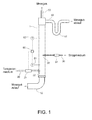
- Fig. 1 an embodiment of a pipe stripper (1) is shown, in which the material to be measured and the stripping medium flow in direct current from bottom to top.
- the material to be measured is introduced via an inlet (10) from below into the tube stripper (1).
- Above the sample feed (10) is the inlet (20) for a temperature control medium.
- the inlet nozzle (22) is designed such that the material to be measured and the temperature control medium mix quickly, so that the material to be measured is tempered quickly and uniformly.
- Meßgutzulauf (10) and inlet of the temperature control medium (20) or preferably above the inlet of the temperature control medium (20) a stripping medium is fed through a further inlet (30).
- the line for Meßgutabschreib (40) is in the form of a siphon (41).
- a hydrostatic pressure is built up which prevents the sample gas from leaving the tube stripper through the siphon.
- the sample gas flows out of the apparatus through the sample gas outlet (50).
- the overpressure of the measurement gas can be influenced so that the measurement gas can overcome flow resistance in the line path to the analysis devices. In such a case, a forced delivery of the measuring gas, for example by pumping or suction, can be dispensed with.
- the lines are heated, through which the sample gas flows from the stripper to the analysis devices (in Fig. 1 not shown), so that no components condense out of the sample gas by cooling, which would falsify the measurement result.
- a similar effect can be achieved by isolating the lines through which the sample gas flows. With very short lines between sample gas outlet (50) and analysis devices can be dispensed with such measures.
- the execution of the line for Meßgutabschreib (40) in the form of a siphon (41) is not mandatory. According to the invention, it merely has to be ensured that the measurement gas can not escape through this line.
- this can also be achieved, for example, by influencing the fill level of the sample in the stripper by means of actuators in the inlet and / or outlet of the material to be measured in such a way that the liquid level is held above the line for removing the product.
- a measuring sensor which detects the level, as well as a control device, which influences the respective actuators in the inlet and / or outlet of the material to be measured, can be provided.
- This alternative embodiment is not shown in the drawings.
- a measuring sensor (61) for detecting the temperature of the measured material is attached above the inlet (20) for the tempering medium.
- Other temperature sensors (62) can be provided.
- the measurement signals of the one or more temperature sensors (61, 62) are fed to a control device (60), which compares these data with a predetermined setpoint for the temperature and calculates a control deviation. On the basis of a given control algorithm, a further signal from the control device (60) is generated from the control deviation, which signal is passed to an actuator (21) in the inlet (20) of the temperature control medium. If the temperature in the material to be measured is lower than the setpoint, the actuator (21) increases the flow of hot tempering medium. If the temperature in the material to be measured is higher than the setpoint, the flow through the actuator (21) is reduced accordingly.
- the supply of stripping medium can also be influenced by an actuator (31).
- the inlet (32) of the stripping medium is advantageously configured such that the stripping medium flows as uniformly as possible through the material to be measured in cross-section.
- This can be done in different ways, for example by a tube which projects into the liquid phase of the stripper and is provided with a plurality of holes from which the stripping medium flows.
- the stripping medium is passed through a frit in the stripper.
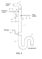
- Fig. 2 shows an embodiment of a stripper (1), in the measured material and stripping medium flow in direct current from top to bottom.
- the material to be measured is fed via an inlet (10) at the top of the stripper.
- a temperature control medium is introduced into the stripper via an inlet (20).
- a stripping medium is fed via an inlet (30).
- the lower end of the stripper (1) is designed in the form of a siphon (41), in which liquid material to be measured collects and ensures a level of material to be measured in the stripper (1).
- the material to be measured leaves the stripper (1) through the siphon (41). Above the height of the upper siphon curvature is located in the stripper (1) an outlet (50) for the sample gas.
- the stripper is partially filled with random packings, which increase the surface area in the stripper (1), whereby an intensification of the mass transfer between the material to be measured and the stripping medium is effected.
- the stripping medium absorbs components from the mixture of sample and temperature control medium and leaves the stripper as sample gas (1).
- a temperature sensor (61) is mounted, which detects the temperature of the material to be measured.
- another temperature sensor (62) may be attached.
- the signals of the or the temperature sensor are fed to a control device (60), in which these data are compared with a predetermined setpoint for the temperature.
- a control device 60
- the deviation from the nominal value and the actual value of the temperature is used to calculate a signal which is sent to an actuator (21) in the inlet (20) of the temperature control medium. If the temperature in the material to be measured is lower than the setpoint, the actuator (21) increases the flow of hot tempering medium. If the temperature in the material to be measured is higher than the setpoint, the flow through the actuator (21) is reduced accordingly.
- Fig. 3 exemplifies an embodiment of a pipe stripper (1), are carried out in the sample and stripping medium in countercurrent.
- the material to be measured is fed via an inlet (10) into the upper part of the stripper and flows downwards.
- a first inlet (20a) is mounted for a temperature control medium.
- a first sensor (61 a) detects the temperature of the supplied material to be measured in the inlet (10), another sensor (63) detects the flow of the inlet.
- the signals of the first temperature sensor (61 a) and the flow sensor (63) are processed in a control algorithm so that the need for temperature control is determined, which is required to heat the material to be measured.
- a corresponding signal is passed from the first control device (60a) to the actuator (21 a) of the first inlet of the tempering medium.
- a second inlet (20b) Below the first inlet (20a) may be provided for the tempering medium, a second inlet (20b).
- Another sensor (61 b) provides a signal for the temperature of the material to be measured in the stripper.
- this signal is compared with a setpoint for the temperature. If the temperature is too low, the control device (60b) sends a signal to an actuator (21b) in the second inlet (20b), which then increases the flow of tempering medium into the stripper. If the temperature at the sensor (61 b) is too high, the flow through the actuator (21 b) is reduced.
- the different control devices (60a, 60b) can also be realized in a common control device which receives all measurement signals and based on an algorithm signals for the actuators (21 a, 21 b) is determined and forwarded. Controllers with such algorithms are also referred to as MIMO (multiple input, multiple output) controllers.
- MIMO multiple input, multiple output controllers.
- the stripping medium is supplied via an inlet (30) and flows from bottom to top through the stripper.
- components are stripped out of the mixture of measurement material and temperature control medium flowing from top to bottom and leave the stripper together with the stripping medium as the measurement gas through an outlet (50) at the upper end.
- the material to be measured leaves the stripper through an outlet (40) at the lower end.
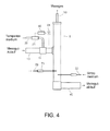
- Fig. 4 shows another embodiment of a countercurrent pipe stripper. Analogous to Fig. 3 the material to be measured is fed into the upper part of the stripper. However, the tempering of the material to be measured takes place before it enters the stripper.
- a mixing device (11) in the inlet (10) of the material to be measured is provided, in which in addition to the material to be measured and the temperature control medium is introduced.
- a measuring sensor (61) determines the mixing temperature after the mixing device and passes a measuring signal to a control device (60). By comparison with a predetermined setpoint, a control algorithm calculates a signal for an actuator (21) in the inlet (20) of the temperature control medium.
- a stripping medium is introduced into the material to be measured through an inlet (30) and flows upwards, counter to the direction of flow of the material being measured, leaving the stripper at the lower end through an outlet (40).
- further substances may be introduced into the stripper through one or more further feeds (70). These substances can be used, for example, as reference substances for an analysis method or for calibration in an analysis device, for example as an internal standard in chromatography.
- the inlet or the inlets (70) can be attached at different locations on the stripper (1) or else at the inlet of the material to be measured (10), for example at the mixing device (11). It only has to be ensured that the substances with the sample gas leave the stripper and are sent to the analysis devices. In the case of incorporation of the additional substances in the sample, for example, this is given when the substances through the stripping medium partially or completely into the sample gas be stripped out. However, the substances can also be introduced, for example, in gaseous form into the gas phase of the stripper or directly into the measurement gas.
- the inlet or the inlets (70) may be provided with an actuator (71) to influence the flow.
- feeds (70) can be attached to other substances.
- the section of the stripping apparatus in which mass transfer between gas and liquid phase takes place, can be provided with internals to promote the mass transfer.
- These can be fixed installations. But it is also possible that these are loose internals. Examples of corresponding installations are baffles or turbulators, which ensure turbulence in particular of the liquid flow.
- ordered or disordered packages or packed beds can be incorporated, as e.g. from the distillation or absorption technique are known.
- the supply of tempering medium may be the only heat source, but it may also be additional heat sources.
- the stripper may be provided with a heating jacket, which is designed as a double tube.
- the product to be measured, the tempering medium and the stripping medium flow in the inner tube while a heating medium flows through the outer tube.
- Suitable heating media may be hot water, hot product or even steam.
- the stripper can also be provided on its outside with a coil or a coil of half-tubes, through which a heating medium flows and releases heat through the wall to the gas and liquid phase in the stripper. If such an additional heat source is used, it makes the basic contribution to the heating of the material to be measured.
- the temperature control to the desired setpoint temperature in the material to be measured is realized as in the variant without additional heat source by supplying a tempering medium into the material to be measured.
- An advantage of the invention is the fact that by means of the method according to the invention or when using the device according to the invention temperature fluctuations, for example in the feed of the material to be measured, can be compensated very quickly. As a result, a substantially uniform temperature in the material to be measured and thus in the sample gas to the analysis devices can be ensured. Furthermore, by increasing the temperature in the material to be measured, the spectrum of detectable substances is widened. In particular, if process steam is available in process engineering plants, the inventive method also has significant cost advantages over alternatives such as electric heating.
- the structure of the stripping device used is schematically shown in FIG Fig. 1 shown.
- the material to be measured passes from below into the stripper by means of a sample pump or by using the hydrostatic pressure (1).
- the material flow is monitored by an upstream Magnetic-Inductive Flowmeter (MID).
- MID Magnetic-Inductive Flowmeter
- About 30 cm above the measuring well inlet (10) is a horizontally installed steam injector (22), which injects steam at a temperature of about 130 ° C directly into the material to be measured and this heated to the desired temperature.
- the sensor (61) used for the temperature control is located at a distance of approx. 20 cm above the injector. Purified air is fed as stripping medium into the stripper approx. 40 cm above the steam injector (30) and led upwards in direct current with the material to be measured.
- a second temperature sensor (62) is located approximately 20 cm above the stripper inlet (32) and serves as a temperature monitor for the safety circuit.
- the material to be measured leaves the stripper at the upper end via an outlet (40) and passes through a siphon (40) into the wastewater.
- the stripping air enriched with components stripped out of the material to be measured leaves the stripper at the highest point as the measuring gas.
- a water column of approx. 30 cm in height in the siphon generates an overpressure of approx. 30 mbar, which ensures that the sample gas can not escape through the siphon.
- the overpressure which can be monitored by a manometer, is designed so that flow resistances of the downstream sample preparation are overcome by the sample gas. Such resistances result in the concrete test arrangement through a filter for the retention of aerosols and a flow meter in the flow path of the sample gas.
- the sample gas line from the stripper to the analysis equipment is continuously heated and insulated. The temperature is chosen so that the sample gas does not condense, so it corresponds at least to the temperature at the outlet from the stripper.
- the analysis device used is a flame ionization detector (FID), in which the sample gas is analyzed for the sum of all hydrocarbon-containing compounds.
- the measurement signal is provided via various outputs (analog and digital) for further processing.
- THF tetrahydrofuran
- Example 1 Water vapor (4 bar absolute, about 130 ° C) introduced into the material to be measured to adjust the respective temperature.
- Fig. 5 shows the results for two different cases: In the first case (square), the sample was pumped into the stripper at 15 ° C, in the second case (circle) at 22 ° C.
- the maximum value of tempering medium which can be supplied to the stripper is limited inter alia by the pressure difference between stripper and source of the tempering medium.
- the steam used as tempering medium originated from a steam network with an approximately constant pressure of 4 bar absolute. At an absolute pressure of about 1 bar in the stripper, the maximum available feed stream of steam was 6 kg / h. Due to this limitation, the measured material in the first case could not be heated as far as in the second case. How out Fig. 5 As can be clearly seen, the height of the FID (arbitrary unit) signal is highly dependent on the temperature of the material being measured. Furthermore, it can be seen that the inlet temperature of the material to be measured hardly plays a role for the material being measured. Although more steam is required to heat the colder material to set the same temperature, the respective signals obtained at that temperature are nearly identical. The dilution effect due to the different amounts of supplied steam is therefore negligible.
- Fig. 6 shows the dependence of the FID signal (arbitrary unit) for two different scenarios: First, the flow of material was kept constant at 60 l / h and the supply of stripping air varied from 20 l / h to 100 l / h. The obtained FID signals are in Fig. 6 marked with a circle.
Landscapes
- Chemical & Material Sciences (AREA)
- Health & Medical Sciences (AREA)
- Life Sciences & Earth Sciences (AREA)
- Chemical Kinetics & Catalysis (AREA)
- Biochemistry (AREA)
- Medicinal Chemistry (AREA)
- Physics & Mathematics (AREA)
- Analytical Chemistry (AREA)
- Food Science & Technology (AREA)
- General Health & Medical Sciences (AREA)
- General Physics & Mathematics (AREA)
- Immunology (AREA)
- Pathology (AREA)
- Engineering & Computer Science (AREA)
- Sampling And Sample Adjustment (AREA)
- Heat Treatment Of Articles (AREA)
Abstract
Description
- Die vorliegende Erfindung betrifft ein Verfahren zur Temperierung eines Messgutes in einem Stripper, in den mindestens ein Strippmedium eingebracht wird und Komponenten zumindest teilweise aus dem Messgut in das Strippmedium übergehen. Daneben betrifft die Erfindung ein Verfahren zur Analyse eines Messgutes, wobei das Messgut einem Stripper zugeführt wird, mindestens ein Strippmedium in das Messgut eingebracht wird, Komponenten zumindest teilweise aus dem Messgut in das Strippmedium übergehen und das so erhaltene Messgas in eine Analyseeinrichtung geleitet wird. Weiterhin betrifft die Erfindung eine Vorrichtung zum Strippen von Komponenten aus einem Messgut umfassend ein Grundelement mit mindestens einem Einlass und mindestens einem Auslass für das Messgut, mindestens einem Einlass für mindestens ein Strippmedium, mindestens einem Auslass für Messgas, das sich aus Strippmedium und aus dem Messgut ausgestrippten Komponenten zusammensetzt, mindestens einem weiteren Einlass für ein Temperiermedium oder mehrere Temperiermedien und mindestens einem Messfühler zur Aufnahme der Temperatur des Messgutes. Bevorzugte Ausführungsformen sind den Unteransprüchen und der Beschreibung zu entnehmen. Vom Rahmen der vorliegenden Erfindung werden selbstverständlich auch Kombinationen bevorzugter Ausführungsformen umfasst.
- Unter "Strippen" wird in der Verfahrenstechnik üblicherweise ein Prozess verstanden, bei dem ein Gas durch eine Flüssigkeit geleitet wird, wobei einige Komponenten aus der Flüssigkeit in die Gasphase übergehen. Ob und in welchem Maße Komponenten in die Gasphase übergehen, hängt im Wesentlichen von den physikalischen und chemischen Eigenschaften der Substanzen in Flüssig- und Gasphase sowie den Prozessbedingungen wie Druck und Temperatur ab.
- Als Strippvorrichtungen oder "Stripper" werden häufig Kolonnen oder Säulen eingesetzt, die meist in vertikaler Richtung röhrenförmig ausgebildet sind. In der Betriebsweise wird zwischen Gleich- und Gegenstromprinzip einerseits sowie kontinuierlichem und diskontinuierlichem Betrieb andererseits unterschieden. Beim Gleichstromprinzip wird das gasförmige Strippmedium in Fließrichtung mit dem Flüssigkeitsstrom geleitet, beim Gegenstromprinzip bewegen sich die Ströme in entgegengesetzter Richtung. Beim kontinuierlichen Betrieb strömen Flüssigkeit und Gas kontinuierlich durch die Strippvorrichtung. Beim diskontinuierlichen Betrieb hingegen wird beispielsweise eine Menge an Flüssigkeit in der Strippvorrichtung vorgelegt, durch die anschließend über eine gewisse Zeitspanne ein gasförmiges Strippmedium strömt.
- Strippvorrichtungen werden für Stofftrennungen zu unterschiedlichen Zwecken eingesetzt. Beispielsweise werden industrielle Abwässer in großtechnischen Anlagen kontinuierlich aufbereitet und gereinigt. Stripper werden auch eingesetzt, um in prozesstechnischen Anlagen Wertprodukte zu gewinnen oder zu reinigen. Häufig handelt es sich dabei um Zwischenschritte bei mehrstufigen Verfahren. Ein Beispiel aus der Petrochemie ist das Dampfstrippen von Naphtha- und Kerosinfraktionen bei der Rohöldestillation. Ein weiteres Einsatzgebiet von Strippvorrichtungen ist die Aufbereitung von Proben zu Analysezwecken. In Kombination mit einer oder mehreren Analyseeinrichtungen werden Stripper beispielsweise zur Überwachung von Abwasser, Kühlwasser oder auch Produktströmen in verfahrenstechnischen Anlagen eingesetzt. Ein Ziel ist dabei, Verunreinigungen der genannten Medien, z.B. durch Kohlenwasserstoffe im Spurenbereich (ppm) nachzuweisen.
- Die Palette an nachweisbaren Substanzen erstreckt sich über einen weiten Bereich von organischen Verbindungen wie leicht- bis schwersiedende Kohlenwasserstoffe, unpolare und polare Kohlenwasserstoffe, z.B. Aromaten, Ester, Alkohole, Amine, Phenole, bis hin zu anorganischen Verbindungen wie Schwefelwasserstoff oder Ammoniak. Die Substanzen können unterschiedliche Löslichkeiten in Wasser aufweisen. Der Strippvorgang ist stark temperaturabhängig. Das Austreiben einzelner Substanzen geschieht bei verschiedenen Temperaturen unterschiedlich effizient. Einige Substanzen lassen sich erst bei höheren Temperaturen signifikant ausstrippen. Der Artikel "Optimization of the open stripping system for the analysis of trace organics in water" von Borén et al. (Journal of Chromatography, 348 (1985), S. 67-78) zeigt die Ergebnisse des Ausstrippens von verschiedenen polaren und unpolaren Substanzen unterschiedlicher Volatilität aus Wasser bei 30°C, 60°C und 90°C. Durch Temperaturschwankungen im Messgut, in obigem Beispiel verunreinigtes Wasser, oder in der Umgebung des Strippers und den Analyseeinrichtungen können erhebliche Ungenauigkeiten bei der Bestimmung der einzelnen Substanzen auftreten. Auch natürliche Änderungen der Umgebungstemperatur im jahreszeitlichen Verlauf und im Tag-Nacht-Zyklus können die Analyseergebnisse erheblich beeinflussen.
- Insbesondere für Strippvorrichtungen, die zu Analysezwecken eingesetzt werden, sind Möglichkeiten bekannt, das Messgut zu temperieren, um die Auswirkungen von Temperaturschwankungen abzuschwächen oder gänzlich auszugleichen.
- In
US 4,154,086 wird eine Vorrichtung und ein Verfahren offenbart zur Detektion von Spuren flüchtiger organischer Substanzen in Wasser. Die Vorrichtung besteht aus einer Kolonne, in die im unteren Teil Wasser im Gegenstrom zu einem Strippgas geführt wird. Das Wasser wird über einen Wärmetauscher temperiert, der beispielhaft als von Dampf durchströmte Heizschlange ausgeführt ist. Das aufsteigende Gas, das aus dem Strippgas, ausgestrippten organischen Komponenten und eventuell Anteilen von Wasser besteht, wird durch einen Wärmetauscher geleitet, der so betrieben wird, dass die Wasseranteile auskondensieren. Der verbleibende Gasstrom wird einer Analyseeinrichtung zugeführt. -
US 6,485,688 beschreibt einen Gegenstrom-Stripper zur Abtrennung von polaren und unpolaren flüchtigen organischen Substanzen aus Abwasser. Der Stripper besteht aus einer Säule, an deren unterem Ende sich ein u-formiger Abschnitt anschließt, der so gestaltet ist, dass sich aufgrund des hydrostatischen Drucks im Stripper eine Flüssigkeitssäule ausbildet. In den unteren Bereich des Strippers wird ein Strippgas eingebracht, das entgegen der Fließrichtung der Flüssigkeit nach oben strömt. Dabei werden flüchtige Komponenten aus der Abwasserprobe ausgestrippt und mit dem Strippgas aus einer Öffnung im oberen Teil des Strippers zu Analyseeinrichtungen geleitet. Die Möglichkeit der Erwärmung des Messgutes wird allgemein erwähnt, es finden sich allerdings keine konkreten Hinweise auf die Ausgestaltung einer Heizung. -
US 6,436,710 beschreibt ebenfalls eine Vorrichtung und ein Verfahren zur Analyse von flüchtigen organischen Substanzen in einer Abwasserprobe. Dabei wird ein Inertgas in eine flüssige Probe geleitet, löst dabei flüchtige Komponenten aus der Flüssigkeit und überführt sie in die Gasphase. Im Gasraum ist ein Sensor angebracht, der Messinformationen über die flüchtigen organischen Komponenten an eine Analyseeinrichtung weiterleitet. Die flüssige Probe kann durch übliche Heizvorrichtungen erhitzt werden. - In dem deutschen Gebrauchsmuster
DE 8804409 wird ein Gerät offenbart, das geeignet ist, flüchtige organische Stoffe aus einer flüssigen Phase, beispielsweise Abwasser, zu extrahieren und einer Analyse zugänglich zu machen. Das Gerät kann mit einer Temperaturregelung versehen sein, die so betrieben werden kann, dass das Messgut während des Strippprozesses auf einer konstanten Temperatur gehalten wird. Als Mittel zum Heizen ist beispielhaft eine elektrische Heizung offenbart. - In
DE 601 09 191 wird eine Vorrichtung und ein Verfahren zur kontinuierlichen Behandlung von Industrieabwasser durch Strippung mit Wasserdampf beschrieben. Bei der Vorrichtung handelt es sich um eine Strippsäule, bei der das Abwasser im oberen Teil und der Wasserdampf im unteren Teil der Säule zugeführt werden. Die Zuläufe und das Rücklaufverhältnis am Kopf der Säule können über Stellorgane so beeinflusst werden, dass eine im Zu- und/ oder Ablauf des Abwassers gemessene Konzentration an interessierenden Komponenten auf einen gewünschten Wert eingestellt wird. - Der im Folgenden beschriebenen Erfindung lag die Aufgabe zugrunde, eine Vorrichtung und ein Verfahren zu entwickeln, mit Hilfe derer ein Messgut in einem Stripper schnell und effizient auf eine gewünschte Temperatur temperiert werden kann. Die Vorrichtung sollte konstruktiv einfach und kostengünstig im Betrieb sein. Dabei sollten das Verfahren und die Vorrichtung sowohl für kontinuierlichen als auch für diskontinuierlichen Betrieb geeignet sein. Außerdem sollten das Verfahren und die Vorrichtung auf dem Gebiet der Analytik einsetzbar sein.
- Zur Lösung dieser Aufgabe wird ein Verfahren vorgeschlagen zur Temperierung eines Messgutes in einem Stripper, in den mindestens ein Strippmedium eingebracht wird und Komponenten zumindest teilweise aus dem Messgut in das Strippmedium übergehen, wobei Dampf mindestens eines Temperiermediums in das Messgut eingebracht wird.
- Daneben wird ein Verfahren vorgeschlagen zur Analyse eines Messgutes, wobei das Messgut einem Stripper zugeführt wird, mindestens ein Strippmedium in das Messgut eingebracht wird, Komponenten zumindest teilweise aus dem Messgut in das Strippmedium übergehen und das so erhaltene Messgas in eine Analyseeinrichtung geleitet wird, wobei das Messgut temperiert wird, indem Dampf mindestens eines Temperiermediums in das Messgut eingebracht wird.
- Weiterhin wird eine Vorrichtung zum Strippen wie eingangs beschrieben vorgeschlagen.
- Unter Temperierung wird im Folgenden der Vorgang verstanden, eine Substanz oder eine Mischung von Substanzen auf eine gewünschte Temperatur zu bringen. Erfindungsgemäß erfolgt die Temperierung eines Messgutes dadurch, dass direkt in das Messgut ein Temperiermedium eingebracht wird oder mehrere Temperiermedien eingebracht werden. Bevorzugt wird das Temperiermedium oder werden die Temperiermedien dampfförmig zugeführt. Die Begriffe "dampfförmig" und "gasförmig" bzw. "Dampf" und "Gas" werden im Folgenden als gleichwertig angesehen. Besonders bevorzugt wird das Temperiermedium oder werden die Temperiermedien direkt in ein im Wesentlichen flüssiges Messgut eingeleitet. Bei mehreren Temperiermedien kann es sich zum einen um eine einzige Substanz handeln, die über mehrere Zuläufe zugeführt wird. Zum anderen werden damit auch unterschiedliche Substanzen bezeichnet, die über einen oder mehrere Zuläufe eingebracht werden. Wird das Temperiermedium oder werden die Temperiermedien dampfförmig in das Messgut eingebracht, so kondensiert der Dampf in Abhängigkeit von Druck- und Temperaturbedingungen teilweise oder vollständig und gibt Wärme an das Messgut ab. Das entstehende Kondensat vermischt sich mit der flüssigen Phase des Messgutes. Selbstverständlich kann das Messgut zusätzlich zur Temperierung mittels Einbringen von einem oder mehreren Temperiermedien auf konventionelle Art temperiert werden, beispielsweise durch eine Beheizung über die Wandung des Strippers, durch Heizelemente im Innern des Strippers oder dem Stripper vorgeschaltete Wärmetauscher. Oft ist es jedoch hinreichend, die Temperierung nur mittels Einbringen eines oder mehrerer Temperiermedien in das Messgut vorzunehmen.
- Das Messgut kann aus unterschiedlichen Substanzen bestehen. Beispielsweise kann das Messgut zum Großteil aus einer Hauptkomponente bestehen, die mit verschiedenen weiteren Substanzen vermischt ist, und von denen zumindest einige teilweise oder vollständig durch Strippen aus der Hauptkomponente entfernt werden können. Bevorzugt handelt es sich bei dem Messgut im Wesentlichen um Wasser, das mit organischen oder anorganischen Verbindungen verunreinigt sein kann. Das Messgut kann auch ein Produkt eines verfahrenstechnischen Prozesses sein, das noch Nebenprodukte oder sonstige Substanzen enthält. Das Messgut ist im Wesentlichen flüssig, wenn es mit dem Temperiermedium in Kontakt gebracht wird. "Im Wesentlichen" bedeutet in diesem Zusammenhang, dass auch andere Phasen in der Flüssigphase enthalten sein können, beispielsweise gelöste oder ungelöste Gaspartikel oder auch Feststoffe wie Schwebeteilchen oder Kristalle.
- Bei dem Strippmedium handelt es sich bevorzugt um ein Gas oder Gasgemisch, das geeignet ist, nachzuweisende Substanzen aus dem Messgut aufzunehmen. Das Strippmedium sollte keine Substanzen enthalten, die die Analyse der nachzuweisenden Substanzen verfälschen können. Bevorzugt sind beispielsweise Luft oder Stickstoff, die sich gegenüber den nachzuweisenden Substanzen inert verhalten. In Abhängigkeit von den zur Analyse eingesetzten Einrichtungen und Methoden erweist sich insbesondere gereinigte Luft als vorteilhaftes Strippmedium. Die Reinigung der Luft kann beispielsweise katalytisch erfolgen. In Abhängigkeit von dem Messgut und den nachzuweisenden Substanzen kann als Strippmedium auch ein Gas oder Gasgemisch eingesetzt werden, das chemisch mit einer oder mehreren Substanzen reagiert und diese in eine oder mehrere andere Substanzen umwandelt. Diese Ausführungsform eines Strippmediums ist insbesondere für solche Substanzen vorteilhaft, die sich selbst nur schwer in einer Analyseeinrichtung erfassen lassen, deren Umsetzungsprodukte, die durch die Reaktion mit dem Strippmedium entstehen, dagegen leichter erfassbar sind. Außerdem lässt sich diese Ausführungsform vorteilhaft anwenden, wenn eine Substanz analysiert werden soll, die sich nicht oder nur schwer aus dem Messgut ausstrippen lässt, deren Reaktionsprodukt aber leichter in die Gasphase übergeht.
- Durch den Stoffaustausch zwischen Messgut und Strippmedium gehen Komponenten zumindest teilweise aus dem Messgut in die Gasphase über und vermischen sich mit dem Strippmedium. Das so entstehende Messgas kann einer Analyseeinrichtung zugeleitet werden. Prinzipiell lassen sich verschiedenste Analyseeinrichtungen und Analysemethoden zum Nachweis verwenden. Welche Analyseeinrichtung eingesetzt wird bzw. welche Analysemethoden verwendet werden, hängt von den zu bestimmenden Parametern ab. Verbreitet ist die Detektion von Substanzen z.B. mittels Summen-Flammenionisationsdetektoren (FID), Gaschromatographie, Photometrie, Spektroskopie oder Gasdetektoren. Es können auch mehrere Analyseeinrichtungen oder Kombinationen von Analyseeinrichtungen Verwendung finden. Das erfindungsgemäße Verfahren und die erfindungsgemäße Vorrichtung lassen sich vorteilhaft anwenden, um eine breite Palette an Substanzen aus einem Messgut auszustrippen, beispielsweise die eingangs erwähnten, z.B. Cyclohexan, Tetrahydrofuran oder Aceton, Alkohole wie Methanol, Ethanol, Butanol oder Propanol, Acrylate wie Methylacrylat oder Ethylacrylat, Aromaten wie Ethylbenzol, aber auch anorganische Verbindungen wie Schwefelwasserstoff oder Ammoniak. Die Substanzen können dabei in Konzentrationen von mehreren Prozent bis in den Spurenbereich, also wenige ppm oder ppb, einzeln oder in Summe im Messgut vorhanden sein.
- Als Temperiermedien kommen unterschiedliche Stoffe oder Stoffgemische in Betracht. Sie sollten so gewählt werden, dass sie sich mit dem Messgut schnell vermischen und keine Substanzen enthalten, die die Analyse des Messgases verfälschen können. Besteht das Messgut beispielsweise im Wesentlichen aus Wasser mit Verunreinigungen durch organische und/oder anorganische Verbindungen, so eignet sich Wasserdampf als Temperiermedium gut. Bei dem Wasserdampf handelt es sich vorteilhaft um Prozessdampf, wie er in Anlagen der chemischen Industrie üblicherweise in verschiedenen Druckstufungen zur Verfügung steht. Geeignete Druckstufungen sind z.B. (Druck als Absolutangaben):
- 1 bis 2 bar, 120 bis 150 °C
- 4 bis 5 bar, 130 bis 200 °C
- 15 bis 18 bar, 200 bis 300 °C
- 40 bis 45 bar, 250 bis 300 °C
- 50 bis 55 bar, 260 bis 300 °C
- Selbstverständlich können erfindungsgemäß auch Temperiermedien bei anderen Drücken und Temperaturen eingesetzt werden, solange sie in der Lage sind, Wärme an das Messgut abzugeben.
- Wenn es sich bei dem Messgut nicht im Wesentlichen um Wasser, sondern beispielsweise einen Produktstrom aus einer verfahrenstechnischen Anlage handelt, so eignen sich besonders Dämpfe des nahezu reinen Produktes als Temperiermedium. Es können auch andere Stoffe oder Stoffgemische eingesetzt werden, die sich mit dem Produkt gut und schnell mischen und keine Substanzen einbringen, die die Analyseergebnisse verfälschen können.
- Die erfindungsgemäße Strippvorrichtung, im Folgenden auch kurz als Stripper bezeichnet, kann unterschiedlich ausgestaltet sein. Allgemein enthält die Vorrichtung ein Grundelement, das ein oder mehrere, vorzugsweise röhrenförmige Bauteile mit mindestens einem Einlass und mindestens einem Auslass für ein Messgut umfasst. Der Querschnitt der Bauteile kann unterschiedlich ausgeführt sein, beispielsweise quadratisch, rechteckig oder oval. Bevorzugt ist der Querschnitt im Wesentlichen kreisförmig bis völlig rund. Die Querschnittsformen sowie die Durchmesser können für die jeweiligen Bauteile unterschiedlich sein. Häufig ist der Stripper im Wesentlichen vertikal angeordnet. Der Stripper umfasst des Weiteren mindestens einen Messfühler zur Aufnahme der Temperatur des Messgutes.
- Weiterhin weist der Stripper mindestens einen Einlass für ein Strippmedium sowie mindestens einen Auslass für ein Messgas auf. Um das Messgut auf eine gewünschte Temperatur bringen zu können, ist mindestens ein weiterer Einlass für mindestens ein Temperiermedium vorgesehen. Sämtliche Zu- und Abläufe, beispielsweise für Messgut, Strippmedium, Temperiermedium oder Messgas, können mit Einrichtungen versehen sein, mit deren Hilfe die jeweiligen Durchflüsse beeinflusst werden können. Beispiele für derartige Stellorgane sind Kugelhähne, Stellklappen oder Stellventile. Erfindungsgemäß bevorzugt ist in mindestens einem Zulauf eines Temperiermediums ein Stellorgan angebracht, wodurch sich der Zufluss an Temperiermedium in einem Bereich von null bis zu einem Maximalwert variieren lässt. Der Maximalwert ist abhängig von der konkreten Ausgestaltung und Geometrie des Stellorgans sowie der Druckdifferenz über das Stellorgan.
- Der Eintritt des Temperiermediums oder der Temperiermedien in den Stripper kann unterschiedlich realisiert sein. In einer einfachen Ausführungsform eines Einlassstutzens taucht ein Rohr mit dem offenen Ende in die Flüssigphase des Strippers. Eine weitere Ausführungsform stellt ein Rohr dar, das in die Flüssigphase des Strippers eintaucht, wobei der in die Flüssigkeit eintauchende Teil des Rohres mehrere Öffnungen aufweist, aus denen das Temperiermedium ausströmt. Bevorzugt sind Einlassstutzen, die eine gleichmäßige und feine Verteilung des Dampfes sicherstellen und damit eine schnelle und effiziente Erwärmung des Messgutes ermöglichen, beispielsweise Düsen. Besonders bevorzugte Ausführungsformen stellen Dampfinjektoren dar. Sie bestehen im Wesentlichen aus einem Gehäuse, in dem sich eine Venturi-Düse sowie ein konisch ausgebildeter Diffusor befinden. Die beiden Bauteile sind so angeordnet, dass sie einen Ringspalt bilden, dessen Fläche abhängig von der anliegenden Druckdifferenz den Dampfdurchsatz durch den Injektor begrenzt. Der Dampf tritt tangential aus dem Ringspalt in das Messgut aus, wobei er kondensiert. Der Auslass ist derart gestaltet, dass Verwirbelungen entstehen, die für eine schnelle Durchmischung des Temperiermediums mit dem Messgut sorgen. Die Verwirbelungen fördern zudem das Ausstrippen der Komponenten von der flüssigen in die gasförmige Phase.
- Der erfindungsgemäße Stripper kann weitere Einlässe aufweisen, beispielsweise zur Zufuhr einer Substanz, mit Hilfe derer in dem oder den verwendeten Analyseeinrichtungen eine Kalibrierung durchgeführt werden kann. Auch eine Referenz- oder Markierungssubstanz kann durch einen oder mehrere solcher zusätzlichen Einlässe in das Messgut oder das Messgas eingebracht werden. Eine solche Substanz kann auch einem Strippmedium oder einem Temperiermedium zugeführt werden und mit diesen Medien in den Stripper gelangen.
- Liegt ein Medium in einem Zulauf nicht bei einem höheren Druck vor als er im Stripper vorherrscht, wird in aller Regel eine Fördereinrichtung eingesetzt, um diesen Druckunterschied zu überwinden und das Medium in den Stripper zu fördern. In einem solchen Fall kann ein Stellorgan auch in die jeweilige Fördereinrichtung integriert sein, beispielsweise in Form einer Dosierpumpe.
- Ein- und Auslässe für Zu- und Abläufe können an unterschiedlichen Stellen am Stripper angebracht sein. Einige vorteilhafte Kombinationen sind unten stehend in den Beschreibungen der
Fig. 1 bis 4 näher ausgeführt. In einer besonders bevorzugten Ausführungsform umfasst das Grundelement des Strippers ein oder mehrere rohrförmige Bauteile. Das Grundelement ist vorteilhaft im Wesentlichen vertikal angeordnet. Am unteren Ende des Grundelementes ist ein Einlass für ein Messgut vorgesehen. Oberhalb des Messguteinlasses ist mindestens ein Einlass für ein Temperiermedium vorhanden. Oberhalb des Temperiermedium-Einlasses wird ein Strippmedium durch mindestens einen Einlass eingebracht. Das Strippmedium kann auch zwischen Messguteinlass und Temperiermedium-Einlass zugeführt werden. Am oberen Ende des Grundelementes verlässt das Messgut das Grundelement über einen Auslass, vorteilhaft durch eine Leitung, die als Siphon ausgeführt ist. Noch oberhalb des Messgutauslasses ist am Grundelement ein Auslass für das Messgas vorhanden. - Die Temperatur des Messgutes wird bevorzugt mit Hilfe eines oder mehrerer Temperatur-Messfühler erfasst. Auf der Basis der Information über die Temperatur im Messgut wird das Stellorgan oder werden die Stellorgane eines Zulaufs oder mehrerer Zuläufe an Temperiermedium so eingestellt, dass sich die Temperatur im Messgut einem gewünschten Sollwert annähert. In einer bevorzugten Ausführungsform werden Informationen aus dem Temperatur-Messfühler oder den Temperatur-Messfühlern einer Regeleinrichtung zugeführt. Die Regeleinrichtung kann unterschiedlich ausgeführt sein, beispielsweise analog oder digital, als eigenständiges Bauteil oder kombiniert mit einem Messfühler, einem Stellorgan oder beidem. Regelprinzipien und -algorithmen sind dem Fachmann bekannt. In einer besonders bevorzugten Ausführungsform einer Regeleinrichtung wird aus Messinformationen und einem gegebenen Sollwert für die Temperatur ein Signal für das Stellorgan im Zulauf oder Signale für Stellorgane in mehreren Zuläufen des Temperiermediums bestimmt. Die Messinformationen können aus unterschiedlichen Arten von Messfühlern stammen. Bevorzugt wird mittels mindestens eines Temperatur-Messfühlers die Temperatur im Messgut erfasst. Dies kann bereits im Zulauf des Messgutes erfolgen oder an unterschiedlichen Stellen im Grundelement des Strippers. Neben den Messfühlern zur Temperaturerfassung können weitere Messfühler vorhanden sein, beispielsweise zur Aufnahme des Drucks oder Durchflusses an unterschiedlichen Medien. Die Signale dieser Messfühler können einer oder mehreren Regeleinrichtungen ebenfalls als Messinformationen zugeführt werden. Besonders bevorzugt wird dem Messgut mehr Temperiermedium zugeführt, wenn die Temperatur im Messgut niedriger als der Sollwert ist, und weniger Temperiermedium, wenn die Temperatur im Messgut höher als der Sollwert ist. Für den Betrieb der Regeleinrichtung und der Stellorgane ist in der Regel Hilfsenergie erforderlich, meist in Form von elektrischer Energie.
- Es ist jedoch auch möglich, dass die Regelungseinrichtung sowie Stellorgan oder Stellorgane für das Temperiermedium ohne Hilfsenergie auskommen. Die Temperatur im Messgut wird in diesem Fall durch einen Thermostaten erfasst, der die Funktionen eines Temperatur-Messfühlers und einer Regeleinrichtung in einem Bauteil vereint. Der gewünschte Sollwert kann an dem Thermostaten eingestellt werden. Zwischen Thermostaten und Stellorgan oder Stellorganen besteht eine Wirkverbindung, beispielsweise mechanischer, hydraulischer oder pneumatischer Art, über die einer Temperaturabweichung zwischen Messguttemperatur und Sollwert entgegen gewirkt wird. Bei einer besonders bevorzugten Ausführungsform besteht die Wirkverbindung aus einem Rohr, das mit Flüssigkeit gefüllt ist. Als Stellorgane kommen bevorzugt Stellventile zum Einsatz. Steigt die Temperatur im Messgut, dehnt sich die Flüssigkeit vom Thermostaten in Richtung Stellventil aus und drückt im Stellventil, beispielsweise über einen Stellbalg, den Ventilkegel in Richtung des Ventilsitzes, was dazu führt, dass weniger Temperiermedium durch das Ventil strömen kann. Geht die Temperatur zurück, verringert sich das Volumen der Flüssigkeit und der Ventilkegel entfernt sich wieder von dem Ventilsitz, der Durchfluss an Temperiermedium steigt. Die Einstellung am Thermostaten wird so gewählt, dass bei Erreichen des gewünschten Temperatursollwertes, also einer verschwindenden Regelabweichung zwischen Temperatur des Messgutes und Sollwert, eine vorab berechnete Menge an Temperiermedium durch das Stellventil fließt.
- Der oder die Temperatur-Messfühler oder der oder die Thermostate können an unterschiedlichen Stellen der erfindungsgemäßen Vorrichtung angebracht sein. In einer bevorzugten Ausführungsform ist mindestens ein Temperatur-Messfühler oder Thermostat in Fließrichtung des Messgutes hinter dem Einlass eines Temperiermediums angebracht, dessen Stellorgan durch den Messfühler oder Thermostat beeinflusst wird. Besonders bevorzugt befindet sich der Messfühler in der ersten Hälfte der Strecke zwischen dem Einlassstutzen eines Temperiermediums, dessen Stellorgan durch den Messfühler oder Thermostat beeinflusst wird, und dem Auslass des Messgutes. Der optimale Abstand und somit die Länge der Regelstrecke kann an die konkreten Strömungs- und Temperaturverhältnisse von Messgut und Temperiermedium angepasst werden.
- In einer weiteren erfindungsgemäßen Ausführungsform wird ein Temperiermedium oder mehrere Temperiermedien dem Zulauf des Messgutes zugeführt. Temperatur-Messfühler oder Thermostat können erfindungsgemäß im Zulauf des Messgutes oder am Grundelement des Strippers angebracht sein.
- Für die Fertigung der Strippvorrichtung steht eine Vielzahl an Materialien prinzipiell zur Verfügung. Die Strippvorrichtung kann aus einem Material oder aus unterschiedlichen Materialien gefertigt sein. Beispiele für geeignete Materialien sind Stahl, Kunststoff, Glas oder auch Kombinationen daraus. Bevorzugt kommen Bauteile aus nichtrostenden Edelstählen, Tempergrauguss oder auch Kunststoffen wie Polyethylenterephthalat (PTFE) zum Einsatz. Abhängig von dem zu behandelnden Messgut können die erfindungsgemäße Vorrichtung oder Teile davon auch aus speziellen Legierungen hergestellt oder mit speziellen Beschichtungen versehen sein. Einige oder auch alle Bauteile der erfindungsgemäßen Strippvorrichtung können isoliert sein, um Wärmeverluste über die Wände der Bauteile zu verringern. Beispielsweise können Rohrleitungen ummantelt sein. Geeignete Isoliermaterialien sind dem Fachmann bekannt.
- Das erfindungsgemäße Verfahren und die erfindungsgemäße Vorrichtung können, wie oben erwähnt, auf den unterschiedlichsten Gebieten zum Einsatz kommen. Sie finden vorteilhaft Anwendung auf Messgüter, aus denen sich eine oder mehrere Komponenten ausstrippen lassen. Bevorzugt handelt es sich bei dem Messgut im Wesentlichen um Wasser, das mit organischen oder anorganischen Verbindungen verunreinigt sein kann. Ein Anwendungsbereich des erfindungsgemäßen Verfahrens und der erfindungsgemäßen Vorrichtung betrifft die Kontrolle von behandlungsbedürftigem und nicht-behandlungsbedürftigem Abwasser oder Kondensat aus verfahrenstechnischen Anlagen. Ein weiterer Anwendungsbereich ist die Kontrolle von Wasser als Einsatzstoff zu verfahrenstechnischen Anlagen, insbesondere wenn hohe Reinheitsanforderungen an das Wasser als Einsatzstoff gestellt werden. Das Anwendungsfeld der Verfahrenstechnik ist nur als Beispiel anzusehen. Selbstverständlich können das erfindungsgemäße Verfahren und die erfindungsgemäße Vorrichtung auch auf anderen Gebieten Anwendungen finden, beispielsweise in der Kraftwerkstechnik, bei Kläranlagen, in biotechnologischen Anlagen oder in der Trinkwassergewinnung.
- Die Liste der Beispiele ist nicht abschließend zu lesen. Prinzipiell lassen sich das erfindungsgemäße Verfahren und die erfindungsgemäße Vorrichtung bei allen Strippprozessen anwenden, bei denen eine effiziente und schnelle Temperierung eines Messgutes gewünscht und die Zufuhr von Temperiermedium in das Messgut möglich ist.
- Anhand der Zeichnungen wird im Folgenden die Erfindung weiter erläutert, wobei die Zeichnungen als Prinzipdarstellungen zu verstehen sind. Sie stellen keine Beschränkung der Erfindung, beispielsweise im Hinblick auf konkrete Abmessungen oder Ausgestaltungsvarianten von Bauteilen des Strippers, dar. Es zeigen:
- Fig. 1:
- Prinzipskizze eines von unten beschickten Gleichstrom-Rohrstrippers
- Fig. 2:
- Prinzipskizze eines von oben beschickten Gleichstrom-Rohrstrippers
- Fig. 3:
- Prinzipskizze eines Gegenstrom-Rohrstrippers
- Fig. 4:
- Prinzipskizze eines Gegenstrom-Rohrstrippers mit zusätzlichem Gaszulauf
- Fig. 5:
- Abhängigkeit eines FID-Signals von der Temperatur des Messgutes
- Fig. 6:
- Abhängigkeit eines FID-Signals von den Durchflussraten an Messgut und Strippmedium für eine konstante Temperatur
-
- 1
- Stripper / Rohrstripper
- 10
- Zulauf Messgut
- 11
- Mischeinrichtung
- 20
- Zulauf Temperiermedium
- 21
- Stellorgan Temperiermedium
- 22
- Einlassstutzen Temperiermedium
- 30
- Zulauf Strippmedium
- 31
- Stellorgan Strippmedium
- 32
- Einlassstutzen Strippmedium
- 40
- Auslass Messgut
- 41
- Siphon
- 50
- Auslass Messgas
- 60
- Regeleinrichtung
- 61
- Temperaturmessfühler
- 62
- Temperaturmessfühler
- 63
- Durchflussmessfühler
- 70
- zusätzlicher Zulauf
- 71
- Stellorgan zusätzlicher Zulauf
- Gleichartige Einrichtungen, die mehrfach vorhanden sein können, werden zusätzlich mit den Buchstaben a, b, c, etc. bezeichnet, z.B. mehrere Zuläufe für Temperiermedien (20a, 20b).
- In
Fig. 1 ist ein Ausführungsbeispiel eines Rohrstrippers (1) dargestellt, bei dem das Messgut und das Strippmedium im Gleichstrom von unten nach oben strömen. Das Messgut wird über einen Zulauf (10) von unten in den Rohrstripper (1) eingebracht. Oberhalb des Messgut-Zulaufes (10) befindet sich der Zulauf (20) für ein Temperiermedium. Der Einlassstutzen (22) ist derart ausgestaltet, dass sich Messgut und Temperiermedium schnell vermischen, sodass das Messgut schnell und gleichmäßig temperiert wird. Zwischen Messgutzulauf (10) und Zulauf des Temperiermediums (20) oder bevorzugt oberhalb des Zulaufs des Temperiermediums (20) wird ein Strippmedium durch einen weiteren Zulauf (30) zugeführt. Durch die Zufuhr des gasförmigen Strippmediums werden Komponenten aus der Mischung aus Messgut und Temperiermedium ausgestrippt. Am oberen Ende des Strippers zweigen zwei Leitungen ab, wovon eine für die Ableitung des Messgutes und die andere für die Abführung des Messgases vorgesehen sind. Die Leitung zur Messgutabfuhr (40) ist in Form eines Siphons (41) ausgebildet. Durch die in dem Siphon sich befindende Flüssigkeit wird ein hydrostatischer Druck aufgebaut, der das Messgas daran hindert, den Rohrstripper durch den Siphon zu verlassen. Stattdessen strömt das Messgas durch den Messgas-Auslass (50) aus der Apparatur. Durch eine geeignete Dimensionierung des Siphons kann der Überdruck des Messgases so beeinflusst werden, dass das Messgas Strömungswiderstände im Leitungsweg zu den Analyseeinrichtungen überwinden kann. In einem solchen Fall kann auf eine Zwangsförderung des Messgases, beispielsweise durch Abpumpen oder Absaugen, verzichtet werden.
Vorteilhaft werden die Leitungen beheizt, durch die das Messgas vom Stripper bis zu den Analyseeinrichtungen strömt (inFig. 1 nicht abgebildet), damit aus dem Messgas keine Komponenten durch Abkühlung auskondensieren, wodurch das Messergebnis verfälscht würde. Ein ähnlicher Effekt kann durch eine Isolierung der Leitungen, durch die das Messgas strömt, erzielt werden. Bei sehr kurzen Leitungen zwischen Messgas-Auslass (50) und Analyseeinrichtungen kann auf derartige Maßnahmen verzichtet werden.
Die Ausführung der Leitung zur Messgutabfuhr (40) in Form eines Siphons (41) ist nicht zwingend. Erfindungsgemäß muss lediglich sichergestellt werden, dass das Messgas nicht durch diese Leitung entweichen kann. Dies kann alternativ beispielsweise auch dadurch erreicht werden, dass durch Stellorgane im Zu- und/oder Ablauf des Messgutes der Füllstand des Messgutes im Stripper derart beeinflusst wird, dass der Flüssigkeitspegel oberhalb der Leitung zur Messgutabfuhr gehalten wird. Hierzu kann ein Messfühler, der den Füllstand erfasst, sowie eine Regeleinrichtung, die die jeweiligen Stellorgane im Zu- und/oder Ablauf des Messgutes beeinflusst, vorgesehen sein. Diese alternative Ausführungsform ist in den Zeichnungen nicht dargestellt. Oberhalb des Zulaufs (20) für das Temperiermedium ist ein Messfühler (61) zur Erfassung der Temperatur des Messgutes angebracht. Es können noch weitere Temperaturmessfühler (62) vorgesehen werden. Die Messsignale des einen oder der mehreren Temperaturmessfühler (61, 62) werden einer Regeleinrichtung (60) zugeführt, die diese Daten mit einem vorgegebenen Sollwert für die Temperatur vergleicht und eine Regelabweichung berechnet. Auf Basis eines gegebenen Regelalgorithmus wird aus der Regelabweichung ein weiteres Signal von der Regeleinrichtung (60) erzeugt, das an ein Stellorgan (21) im Zulauf (20) des Temperiermediums geleitet wird. Ist die Temperatur im Messgut niedriger als der Sollwert, erhöht das Stellorgan (21) den Durchfluss an heißem Temperiermedium. Ist die Temperatur im Messgut höher als der Sollwert, wird der Durchfluss durch das Stellorgan (21) entsprechend reduziert.
Auch die Zufuhr an Strippmedium kann durch ein Stellorgan (31) beeinflusst werden. Der Einlass (32) des Strippmediums ist vorteilhaft derart gestaltet, dass das Strippmedium im Querschnitt möglichst gleichförmig durch das Messgut strömt. Dies kann auf unterschiedliche Arten geschehen, beispielsweise durch ein Rohr, das in die Flüssigphase des Strippers ragt und mit mehreren Löchern versehen ist, aus denen das Strippmedium strömt. Bevorzugt wird das Strippmedium über eine Fritte in den Stripper geleitet. -
Fig. 2 zeigt ein Ausführungsbeispiel eines Strippers (1), bei dem Messgut und Strippmedium im Gleichstrom von oben nach unten strömen. Das Messgut wird über einen Zulauf (10) am oberen Ende dem Stripper zugeführt. Unterhalb des Messgut-Zulaufes (10) wird ein Temperiermedium über einen Zulauf (20) in den Stripper eingebracht. Wiederum unterhalb des Temperiermedium-Zulaufes (20) wird ein Strippmedium über einen Zulauf (30) zugeführt. Das untere Ende des Strippers (1) ist in Form eines Siphons (41) ausgestaltet, in dem sich flüssiges Messgut sammelt und für einen Füllstand an Messgut im Stripper (1) sorgt. Das Messgut verlässt den Stripper (1) durch den Siphon (41). Oberhalb der Höhe der oberen Siphonkrümmung befindet sich im Stripper (1) ein Auslass (50) für das Messgas. Der Flüssigkeitsstand im Stripper (1) sorgt dafür, dass das Messgas nicht durch den Siphon (41) entweicht. Vorteilhaft ist bei dieser Ausführungsform der Stripper teilweise mit Füllkörpern gefüllt, die die Oberfläche im Stripper (1) vergrößern, wodurch eine Intensivierung des Stoffaustausches zwischen Messgut und Strippmedium bewirkt wird. Das Strippmedium nimmt Komponenten aus der Mischung aus Messgut und Temperiermedium auf und verlässt als Messgas den Stripper (1). Bevorzugt unterhalb des Zulaufs (20) für das Temperiermedium ist in dem Stripper (1) ein Temperaturmessfühler (61) angebracht, der die Temperatur des Messgutes erfasst. Im Strömungsverlauf weiter unterhalb kann ein weiterer Temperaturmessfühler (62) angebracht sein. Die Signale des oder der Temperaturmessfühler werden einer Regelungseinrichtung (60) zugeleitet, in der diese Daten mit einem vorgegebenen Sollwert für die Temperatur verglichen werden. Auf Basis eines gegebenen Regelalgorithmus berechnet sich aus der Abweichung von Sollwert und Istwert der Temperatur ein Signal, das an ein Stellorgan (21) im Zulauf (20) des Temperiermediums geleitet wird. Ist die Temperatur im Messgut niedriger als der Sollwert, erhöht das Stellorgan (21) den Durchfluss an heißem Temperiermedium. Ist die Temperatur im Messgut höher als der Sollwert, wird der Durchfluss durch das Stellorgan (21) entsprechend reduziert. -
Fig. 3 stellt beispielhaft eine Ausführungsform eines Rohrstrippers (1) dar, bei dem Messgut und Strippmedium im Gegenstrom geführt werden. Das Messgut wird über einen Zulauf (10) in den oberen Teil des Strippers geleitet und strömt nach unten. Unterhalb des Messgut-Zulaufes (10) ist ein erster Zulauf (20a) für ein Temperiermedium angebracht. Ein erster Messfühler (61 a) erfasst die Temperatur des zugeführten Messgutes im Zulauf (10), ein weiterer Messfühler (63) den Durchfluss des Zulaufs. In einer ersten Regeleinrichtung (60a) werden die Signale des ersten Temperaturmessfühlers (61 a) und des Durchflussmessfühlers (63) in einem Regelalgorithmus so verarbeitet, dass der Bedarf an Temperiermedium bestimmt wird, der zu Aufheizung des Messgut-Zulaufs erforderlich ist. Ein entsprechendes Signal wird von der ersten Regeleinrichtung (60a) an das Stellorgan (21 a) des ersten Zulaufs des Temperiermediums geleitet. Unterhalb des ersten Zulaufs (20a) kann ein zweiter Zulauf (20b) für das Temperiermedium vorgesehen sein. Ein weiterer Messfühler (61 b) liefert ein Signal für die Temperatur des Messgutes im Stripper. In einer zweiten Regeleinrichtung (60b) wird dieses Signal mit einem Sollwert für die Temperatur verglichen. Ist die Temperatur zu niedrig, gibt die Regeleinrichtung (60b) ein Signal an ein Stellorgan (21 b) im zweiten Zulauf (20b), das daraufhin den Durchfluss an Temperiermedium in den Stripper erhöht. Ist die Temperatur an dem Messfühler (61 b) zu hoch, wird der Durchfluss durch das Stellorgan (21 b) verringert.
Die unterschiedlichen Regeleinrichtungen (60a, 60b) können auch in einer gemeinsamen Regeleinrichtung realisiert werden, die sämtliche Messsignale empfängt und auf Basis eines Algorithmus Signale für die Stellorgane (21 a, 21 b) ermittelt und weiterleitet. Regeleinrichtungen mit derartigen Algorithmen werden auch als MIMO-Regler (multiple input, multiple output) bezeichnet.
Am unteren Ende des Rohrstrippers (1) wird das Strippmedium über einen Zulauf (30) zugeführt und strömt von unten nach oben durch den Stripper. Dabei werden Komponenten aus dem von oben nach unten fließenden Gemisch aus Messgut und Temperiermedium ausgestrippt und verlassen zusammen mit dem Strippmedium als Messgas durch einen Auslass (50) am oberen Ende den Stripper. Das Messgut verlässt den Stripper durch einen Auslass (40) am unteren Ende. -
Fig. 4 zeigt eine weitere Ausführungsform eines Gegenstrom-Rohrstrippers. Analog zuFig. 3 wird das Messgut im oberen Teil des Strippers zugeführt. Die Temperierung des Messgutes erfolgt nun allerdings vor dem Eintritt in den Stripper. Dazu ist eine Mischeinrichtung (11) im Zulauf (10) des Messgutes vorgesehen, in die neben dem Messgut auch das Temperiermedium eingebracht wird. Ein Messfühler (61) ermittelt die Mischtemperatur nach der Mischeinrichtung und leitet ein Messsignal an eine Regeleinrichtung (60). Durch Vergleich mit einem vorgegebenen Sollwert berechnet ein Regelalgorithmus daraus ein Signal für ein Stellorgan (21) im Zulauf (20) des Temperiermediums. Ist die Mischtemperatur zu niedrig, wird der Durchfluss des Temperiermediums erhöht, ist sie zu hoch, wird der Durchfluss verringert.
Analog zu der Ausführungsform inFig. 3 wird am unteren Ende des Strippers ein Strippmedium durch einen Zulauf (30) in das Messgut eingebracht und strömt nach oben, entgegen der Fließrichtung des Messgutes, das den Stripper am unteren Ende durch einen Auslass (40) verlässt. Zusätzlich zu dem Strippmedium können weitere Substanzen durch einen oder mehrere weitere Zuläufe (70) in den Stripper eingebracht werden. Diese Substanzen können beispielsweise als Referenzsubstanzen für ein Analyseverfahren oder zur Kalibrierung in einer Analyseeinrichtung Verwendung finden, z.B. als interner Standard in der Chromatographie. Der Zulauf oder die Zuläufe (70) können an unterschiedlichen Stellen am Stripper (1) oder auch am Zulauf des Messgutes (10), beispielsweise an der Mischeinrichtung (11), angebracht sein. Es muss lediglich sichergestellt sein, dass die Substanzen mit dem Messgas den Stripper verlassen und zu den Analyseeinrichtungen geleitet werden. Im Fall der Einbringung der zusätzlichen Substanzen in das Messgut beispielsweise ist dies dann gegeben, wenn die Substanzen durch das Strippmedium teilweise oder vollständig in das Messgas ausgestrippt werden. Die Substanzen können aber z.B. auch gasförmig in die Gasphase des Strippers oder direkt in das Messgas eingeleitet werden. Der Zulauf oder die Zuläufe (70) können mit einem Stellorgan (71) versehen sein, um den Durchfluss zu beeinflussen. - Auch wenn nur in der
Fig. 4 ein zusätzlicher Zulauf (70) dargestellt ist, so können selbstverständlich auch bei anderen Ausführungsformen Zuläufe (70) für weitere Substanzen angebracht werden. - Der Abschnitt der Strippvorrichtung, in der Stoffaustausch zwischen Gas- und Flüssigphase stattfindet, kann mit Einbauten versehen sein, um den Stoffaustausch zu fördern. Diese können fest installierte Einbauten sein. Es ist aber auch möglich, dass es sich dabei um lose Einbauten handelt. Beispiele für entsprechende Einbauten sind Leitbleche oder Turbulatoren, die für eine Verwirbelung insbesondere der Flüssigkeitsströmung sorgen. Weiterhin können geordnete oder ungeordnete Packungen oder Füllkörperschüttungen eingebracht sein, wie sie z.B. aus der Destillations- oder Absorptionstechnik bekannt sind.
- Die Zufuhr von Temperiermedium kann die einzige Wärmequelle sein, es können aber auch zusätzliche Wärmequellen vorhanden sein. Beispielsweise kann der Stripper mit einem Heizmantel versehen sein, der als Doppelrohr ausgeführt ist. Messgut, Temperiermedium und Strippmedium strömen dabei im Innenrohr, währen ein Heizmedium durch das Außenrohr fließt. Geeignete Heizmedien können heißes Wasser, heißes Produkt oder auch Dampf sein. Anstelle eines Doppelrohres kann der Stripper auch auf seiner Außenseite mit einer Rohrschlange oder einer Wendel aus Halbrohren versehen sein, durch die ein Heizmedium fließt und Wärme über die Wand an die Gas- und Flüssigphase im Stripper abgibt. Wird eine solche zusätzliche Wärmequelle verwendet, so leistet sie den Grundbeitrag zur Erwärmung des Messgutes. Die Temperierung auf den gewünschten Sollwert der Temperatur im Messgut wird wie bei der Variante ohne zusätzliche Wärmequelle durch die Zufuhr eines Temperiermediums in das Messgut realisiert.
- Ein Vorteil der Erfindung ist darin zu sehen, dass mittels des erfindungsgemäßen Verfahrens bzw. bei Einsatz der erfindungsgemäßen Vorrichtung Temperaturschwankungen, beispielsweise im Zulauf des Messgutes, sehr schnell ausgeglichen werden können. Dadurch kann eine im Wesentlichen gleichmäßige Temperatur im Messgut und somit im Messgas zu den Analyseeinrichtungen sichergestellt werden. Weiterhin wird durch eine Erhöhung der Temperatur im Messgut das Spektrum der nachweisbaren Substanzen erweitert. Insbesondere wenn Prozessdampf in verfahrenstechnischen Anlagen zur Verfügung steht, weist das erfindungsgemäße Verfahren darüber hinaus deutliche Kostenvorteile gegenüber Alternativen wie elektrischer Beheizung auf.
- Der Aufbau der verwendeten Strippeinrichtung ist schematisch in
Fig. 1 dargestellt. Das Messgut gelangt mittels einer Probenpumpe oder unter Nutzung des hydrostatischen Drucks von unten in den Stripper (1). Der Messgutfluss wird dabei durch einen vorgeschalteten Magnetisch-Induktiven Durchflussmesser (MID) überwacht. Etwa 30 cm oberhalb des Messgutzulaufes (10) befindet sich ein horizontal eingebauter Dampfinjektor (22), der Wasserdampf mit einer Temperatur von ca. 130°C direkt in das Messgut injiziert und dieses auf die gewünschte Temperatur erhitzt. Der für die Temperaturregelung eingesetzte Fühler (61) befindet sich im Abstand von ca. 20 cm oberhalb des Injektors. Gereinigte Luft wird als Strippmedium ca. 40 cm oberhalb des Dampfinjektors in den Stripper zugeführt (30) und im Gleichstrom mit dem Messgut nach oben geführt. Die Strecke vom Ort des Einlasses (32) der Strippluft bis zum oberen Ende des Strippers ist ca. 50 cm lang und bildet den Phasentauscher, in dem sich die Strippluft mit den aus dem Messgut ausgetriebenen Komponenten anreichert. Ein zweiter Temperaturfühler (62) befindet sich ca. 20 cm oberhalb des Stripplufteinlasses (32) und dient als Temperaturüberwachung für die Sicherheitsschaltung. - Das Messgut verlässt den Stripper am oberen Ende über einen Auslass (40) und gelangt durch einen Siphon (40) ins Abwasser. Die mit aus dem Messgut ausgestrippten Komponenten angereicherte Strippluft verlässt im höchsten Punkt den Stripper als Messgas. Durch eine Wassersäule von ca. 30 cm Höhe im Siphon wird ein Überdruck von ca. 30 mbar generiert, der dafür sorgt, dass das Messgas nicht durch den Siphon abströmen kann. Der Überdruck, der durch ein Manometer überwacht werden kann, ist so ausgelegt, dass Strömungswiderstände der nachgeschalteten Probenaufbereitung vom Messgas überwunden werden. Solche Widerstände ergeben sich in der konkreten Versuchsanordnung durch ein Filter zur Rückhaltung von Aerosolen und ein Durchflussmessgeräte im Strömungsweg des Messgases. Die Messgasleitung vom Stripper bis zu den Analyseeinrichtungen ist durchgängig beheizt und isoliert. Die Temperatur ist so gewählt, dass das Messgas nicht kondensiert, sie also mindestens der Temperatur am Austritt aus dem Stripper entspricht.
- Als Analyseeinrichtung wird ein Flammen-lonisationsdektor (FID) eingesetzt, in dem das Messgas auf die Summe alle kohlenwasserstoffhaltigen Verbindungen analysiert wird. Das Messsignal wird über verschiedene Ausgänge (analog und digital) zur weiteren Verarbeitung bereitgestellt.
- Als Versuchssubstanz, die in Wasser nachgewiesen werden soll, wurde Tetrahydrofuran (THF) ausgewählt. THF ist in Wasser gut löslich und lässt sich schwer, aber reproduzierbar ausstrippen.
- Das Messgut wird mit einer Pumpe aus einem 100-Liter-Fass zum Strippsystem gefördert. Das Messgut wird durch direkte Injizierung von Wasserdampf auf eine bestimmte Endtemperatur temperiert, die enthaltenen Kohlenwasserstoffe mit Luft ausgestrippt und mit einem FID detektiert. Ein Siemens-Schreiber erfasst das FID-Messsignal und die Temperatur des Messgutes. Die Dampfmenge wird am Dampfmengenmesser, die Messgutmenge am MID und die Strippluftmenge am Strömungsmesser direkt abgelesen und erfasst. Folgende Geräte wurden verwendet:
- Testa FID 123 kalibriert auf Propan (Prüfgas mit 800 ppm Propan vor jeder Messreihe); FID-Messbereiche (MB): MB1 = 10 ppm; MB2 = 200 ppm; MB3 = 1000 ppm (bezogen jeweils auf Propan); Probemenge zum FID: 14 ml/min
- MID kalibriert auf 0-200 l/h Wasser
- ABB Kopfmessumformer mit Pt100-Temperaturfühler 0-100°C kalibriert
- Messgasweg durchgehend auf mindestens 120°C beheizt
- Zunächst wurde untersucht, welche Dampfmengen nötig sind, um das Messgut auf eine bestimmte Temperatur zu erwärmen. Als Messgut wurde Wasser mit einem THF-Gehalt von 40 ppm bei 15°C verwendet. Der Messgutstrom betrug 60 l/h und wurde während des Versuchs konstant gehalten. In der Tabelle 1 sind die erforderlichen Mengen an Dampf (4 bar absolut, ca. 130 °C) für die jeweilige Mischtemperatur angegeben.
Tabelle 1 Mischtemperatur [°C] 15 30 40 50 60 67 Dampfstrom [kg/h] 0 1,3 2,1 3,2 4,3 5,7 - In einem weiteren Versuch wurde das Messgut mit derselben Zusammensetzung wie in Beispiel 1 mit einem Strom von 60 l/h in den Stripper gepumpt. Als Strippmedium wurde gereinigte Luft mit einer Flussrate von 80 l/h eingesetzt. Untersucht wurde die Abhängigkeit des FID-Signals von der Temperatur des Messgutes. Dazu wurde analog zu Beispiel 1 Wasserdampf (4 bar absolut, ca. 130 °C) in das Messgut eingebracht, um die jeweilige Temperatur einzustellen.
Fig. 5 zeigt die Ergebnisse für zwei unterschiedliche Fälle: Im ersten Fall (Quadrat) wurde das Messgut mit 15°C in den Stripper gepumpt, im zweiten Fall (Kreis) mit 22°C. Wie oben beschrieben ist der Maximalwert an Temperiermedium, das dem Stripper zugeführt werden kann, unter anderem durch die Druckdifferenz zwischen Stripper und Quelle des Temperiermediums begrenzt. Im vorliegenden Fall stammte der als Temperiermedium eingesetzte Dampf aus einem Dampfnetz mit annähernd konstantem Druck von 4 bar absolut. Bei einem Absolutdruck von ca. 1 bar im Stripper betrug der maximal zur Verfügung stehende Einsatzstrom an Dampf 6 kg/h. Aufgrund dieser Begrenzung ließ sich das Messgut im ersten Fall nicht so weit erwärmen wie im zweiten Fall. Wie ausFig. 5 deutliche hervorgeht, ist die Höhe des FID-Signals (willkürliche Einheit, "arbitrary unit") stark von der Temperatur des Messgutes abhängig. Weiterhin ist erkennbar, dass die Eintrittstemperatur des Messgutes für das Messgut kaum eine Rolle spielt. Obwohl zur Erwärmung des kälteren Messgutes mehr Dampf erforderlich ist, um dieselbe Temperatur einzustellen, sind die jeweiligen Signale, die bei dieser Temperatur erhalten werden, nahezu identisch. Der Verdünnungseffekt durch die unterschiedlich großen zugeführten Dampfmengen ist demnach vernachlässigbar. - Untersucht wurde der Einfluss einer Variation der Flussraten an Messgut und an Strippmedium. Dazu wurde wiederum ein Messgut mit derselben Zusammensetzung wie in den vorherigen Beispielen in den Stripper gepumpt und durch Einbringen von Wasserdampf auf eine konstante Temperatur von 40°C temperiert.
Fig. 6 zeigt die Abhängigkeit des FID-Signals (willkürliche Einheit, "arbitrary unit") für zwei unterschiedliche Szenarien: Zunächst wurde der Messgutfluss auf 60 l/h konstant gehalten und die Zufuhr an Strippluft von 20 l/h bis 100 l/h variiert. Die erhaltenen FID-Signale sind inFig. 6 mit einem Kreis gekennzeichnet. Anschließend wurde der Zufluss an Strippluft auf 80 l/h konstant eingestellt und die Menge an zugeführtem Messgut von 35 l/h bis 120 l/h variiert. Die Kurve der entsprechenden FID-Signale sind inFig. 6 mit einem Quadrat markiert. Es ist deutlich zu erkennen, dass trotz signifikanter Änderung der Durchflüsse an Messgut und Strippmedium sich das resultierende FID-Signal in einem sehr engen Bereich (79 bis 81) bewegt.
Claims (13)
- Verfahren zur Temperierung eines Messgutes in einem Stripper (1), in den mindestens ein Strippmedium eingebracht wird und Komponenten zumindest teilweise aus dem Messgut in das Strippmedium übergehen, dadurch gekennzeichnet, dass Dampf mindestens eines Temperiermediums in das Messgut eingebracht wird.
- Verfahren zur Analyse eines Messgutes, wobei das Messgut einem Stripper (1) zugeführt wird, mindestens ein Strippmedium in das Messgut eingebracht wird, Komponenten zumindest teilweise aus dem Messgut in das Strippmedium übergehen und das so erhaltene Messgas in eine Analyseeinrichtung geleitet wird, dadurch gekennzeichnet, dass das Messgut temperiert wird, indem Dampf mindestens eines Temperiermediums in das Messgut eingebracht wird.
- Verfahren nach Anspruch 1 oder 2, dadurch gekennzeichnet, dass die Temperatur des Messgutes durch mindestens einen Messfühler (61) erfasst wird und eine Regeleinrichtung (60) auf der Basis eines Vergleichs der Messguttemperatur mit einem vorgegebenen Sollwert mindestens ein Stellorgan (21) in mindestens einem Zulauf (20) eines Temperiermediums so beeinflusst, dass das Stellorgan (21) einer Abweichung zwischen Messguttemperatur und Sollwert entgegenwirkt.
- Verfahren nach Anspruch 1 oder 2, dadurch gekennzeichnet, dass die Temperatur im Messgut durch einen Thermostaten erfasst wird, dem ein Sollwert für die Temperatur vorgegeben ist und der weiterhin mit einem Stellorgan (21) in Wirkverbindung steht, sodass das Stellorgan (21) einer Temperaturabweichung zwischen Messguttemperatur und Sollwert entgegenwirkt.
- Verfahren nach Anspruch 3 oder 4, dadurch gekennzeichnet, dass mindestens ein Messfühler (61) oder Thermostat in Fließrichtung des Messguts in der ersten Hälfte der Strecke zwischen dem Einlassstutzen (22) eines Temperiermediums, dessen Stellorgan (21) durch den Messfühler (61) oder Thermostat beeinflusst wird, und dem Auslass (40) des Messgutes angebracht ist.
- Verfahren nach einem der Ansprüche 1 bis 5, dadurch gekennzeichnet, dass in das Messgut oder Messgas mindestens eine weitere Substanz eingebracht wird, die in einer Analyseeinrichtung als Referenzsubstanz, zur Markierung oder Kalibrierung Verwendung findet.
- Verfahren nach einem der Ansprüche 1 bis 6, dadurch gekennzeichnet, dass es sich bei dem Messgut um Abwasser handelt.
- Verfahren nach Anspruch 7, dadurch gekennzeichnet, dass es sich bei dem Temperiermedium um Wasserdampf handelt.
- Vorrichtung zum Strippen (1) von Komponenten aus einem Messgut, umfassend ein Grundelement mit mindestens einem Einlass (10) und mindestens einem Auslass (40) für das Messgut, mindestens einem Einlass (30) für mindestens ein Strippmedium, mindestens einem Auslass (50) für Messgas, das sich aus Strippmedium und aus dem Messgut ausgestrippten Komponenten zusammensetzt, mindestens einem weiteren Einlass (20) für ein Temperiermedium oder mehrere Temperiermedien und mindestens einem Messfühler (61) zur Aufnahme der Temperatur des Messgutes.
- Vorrichtung nach Anspruch 9, wobei die Vorrichtung weiterhin eine Regeleinrichtung (60) umfasst, die auf Basis eines Vergleichs der Messguttemperatur mit einem vorgegebenen Sollwert mindestens ein Stellorgan (21) im Zulauf (20) eines Temperiermediums beeinflusst.
- Vorrichtung nach Anspruch 10, wobei der Messfühler (61) und die Regeleinrichtung (60) in Form eines Thermostaten realisiert sind, der mit dem Stellorgan (21) im Zulauf (20) eines Temperiermediums in Wirkverbindung steht.
- Vorrichtung nach einem der Ansprüche 9 bis 11, wobei das Grundelement im Wesentlichen aus einem rohrförmigen Bauteil besteht, an dessen unterem Ende ein Einlass (10) für ein Messgut vorgesehen ist, oberhalb des Messguteinlasses (10) mindestens ein Einlass (20) für ein Temperiermedium vorhanden ist, oberhalb des Temperiermedium-Einlasses (20) ein Strippmedium durch mindestens einen Einlass (30) eingebracht wird, am oberen Ende des rohrförmigen Bauteils das Messgut über einen Siphon (41) abgeführt wird und am obersten Ende des rohrförmigen Bauteils ein Auslass (50) für Messgas vorhanden ist.
- Verwendung der Vorrichtung nach einem der Ansprüche 9 bis 12 zur Analyse eines Messgutes.
Priority Applications (3)
| Application Number | Priority Date | Filing Date | Title |
|---|---|---|---|
| EP08154804A EP2110664B1 (de) | 2008-04-18 | 2008-04-18 | Temperierung eines Messgutes in einem Stripper durch direkte Dampfinjektion |
| AT08154804T ATE521889T1 (de) | 2008-04-18 | 2008-04-18 | Temperierung eines messgutes in einem stripper durch direkte dampfinjektion |
| ES08154804T ES2369311T3 (es) | 2008-04-18 | 2008-04-18 | Templado de un producto a medir en un despojador a través de una inyección directa de vapor. |
Applications Claiming Priority (1)
| Application Number | Priority Date | Filing Date | Title |
|---|---|---|---|
| EP08154804A EP2110664B1 (de) | 2008-04-18 | 2008-04-18 | Temperierung eines Messgutes in einem Stripper durch direkte Dampfinjektion |
Publications (2)
| Publication Number | Publication Date |
|---|---|
| EP2110664A1 true EP2110664A1 (de) | 2009-10-21 |
| EP2110664B1 EP2110664B1 (de) | 2011-08-24 |
Family
ID=39752411
Family Applications (1)
| Application Number | Title | Priority Date | Filing Date |
|---|---|---|---|
| EP08154804A Not-in-force EP2110664B1 (de) | 2008-04-18 | 2008-04-18 | Temperierung eines Messgutes in einem Stripper durch direkte Dampfinjektion |
Country Status (3)
| Country | Link |
|---|---|
| EP (1) | EP2110664B1 (de) |
| AT (1) | ATE521889T1 (de) |
| ES (1) | ES2369311T3 (de) |
Cited By (1)
| Publication number | Priority date | Publication date | Assignee | Title |
|---|---|---|---|---|
| CN115575459A (zh) * | 2022-12-08 | 2023-01-06 | 中国核动力研究设计院 | 小型化模块化水质在线监测系统 |
Citations (7)
| Publication number | Priority date | Publication date | Assignee | Title |
|---|---|---|---|---|
| US3441483A (en) | 1967-06-07 | 1969-04-29 | Phillips Petroleum Co | Method of controlling fractionator or stripper temperature by controlling reboiled vapor flow |
| US4154086A (en) | 1978-04-06 | 1979-05-15 | Petro-Tex Chemical Corporation | Apparatus and method for the discovery of volatile organic compounds in water |
| US4737467A (en) | 1987-02-06 | 1988-04-12 | Rice Richard C | Vapor stripping cell and a method for separating organic vapors from an organic substance |
| DE8804409U1 (de) | 1987-04-06 | 1988-06-30 | Rhone-Poulenc Chimie, Courbevoie | Gerät zum Nachweis und/oder zur Messung durch Phasentrennung und -übergang |
| US6436710B1 (en) | 2000-04-24 | 2002-08-20 | General Electric Company | Headspace sampling and monitoring systems and methods |
| US6485688B1 (en) | 2000-04-24 | 2002-11-26 | General Electric Company | On-line sparging sampling and monitoring systems and methods |
| DE60109191T2 (de) | 2000-12-01 | 2006-02-16 | Totalfinaelf France | Verfahren und vorrichtung zur kontinuierlichen behandlung von industriellem abfallwasser durch strippung mit wasserdampf |
Family Cites Families (1)
| Publication number | Priority date | Publication date | Assignee | Title |
|---|---|---|---|---|
| US3386891A (en) * | 1964-12-31 | 1968-06-04 | Phillips Petroleum Co | Alkylate purification by temperature controlled distillation |
-
2008
- 2008-04-18 ES ES08154804T patent/ES2369311T3/es active Active
- 2008-04-18 AT AT08154804T patent/ATE521889T1/de active
- 2008-04-18 EP EP08154804A patent/EP2110664B1/de not_active Not-in-force
Patent Citations (7)
| Publication number | Priority date | Publication date | Assignee | Title |
|---|---|---|---|---|
| US3441483A (en) | 1967-06-07 | 1969-04-29 | Phillips Petroleum Co | Method of controlling fractionator or stripper temperature by controlling reboiled vapor flow |
| US4154086A (en) | 1978-04-06 | 1979-05-15 | Petro-Tex Chemical Corporation | Apparatus and method for the discovery of volatile organic compounds in water |
| US4737467A (en) | 1987-02-06 | 1988-04-12 | Rice Richard C | Vapor stripping cell and a method for separating organic vapors from an organic substance |
| DE8804409U1 (de) | 1987-04-06 | 1988-06-30 | Rhone-Poulenc Chimie, Courbevoie | Gerät zum Nachweis und/oder zur Messung durch Phasentrennung und -übergang |
| US6436710B1 (en) | 2000-04-24 | 2002-08-20 | General Electric Company | Headspace sampling and monitoring systems and methods |
| US6485688B1 (en) | 2000-04-24 | 2002-11-26 | General Electric Company | On-line sparging sampling and monitoring systems and methods |
| DE60109191T2 (de) | 2000-12-01 | 2006-02-16 | Totalfinaelf France | Verfahren und vorrichtung zur kontinuierlichen behandlung von industriellem abfallwasser durch strippung mit wasserdampf |
Non-Patent Citations (2)
| Title |
|---|
| BOREN ET AL.: "Op- timization of the open stripping system for the analysis of trace organics in water", JOURNAL OF CHROMATOGRAPHY, vol. 348, 1985, pages 67 - 78, XP002497795 |
| H. BORÉN ET AL.: "Optimization of the Open Stripping System for the Analysis of Trace Organics in Water", JOURNAL OF CHROMATOGRAPHY, vol. 348, 1985, Amsterdam, pages 67 - 78, XP002497795 * |
Cited By (1)
| Publication number | Priority date | Publication date | Assignee | Title |
|---|---|---|---|---|
| CN115575459A (zh) * | 2022-12-08 | 2023-01-06 | 中国核动力研究设计院 | 小型化模块化水质在线监测系统 |
Also Published As
| Publication number | Publication date |
|---|---|
| ES2369311T3 (es) | 2011-11-29 |
| EP2110664B1 (de) | 2011-08-24 |
| ATE521889T1 (de) | 2011-09-15 |
Similar Documents
| Publication | Publication Date | Title |
|---|---|---|
| EP3071964B1 (de) | Vorrichtung und verfahren zur detektion von gas | |
| EP2046493B1 (de) | Vorrichtung und verfahren zur handhabung von multikomponenten-gemischen | |
| DE3535029C2 (de) | ||
| DE102011050314A1 (de) | Lösungsmittel-Entgasungs-System für HPLC-Systeme mit geringen Flussraten | |
| EP2110664B1 (de) | Temperierung eines Messgutes in einem Stripper durch direkte Dampfinjektion | |
| EP2163878A1 (de) | Verfahren und Vorrichtung zur Probenahme kryogener Flüssigkeiten | |
| EP3642592B1 (de) | Vorrichtung und verfahren zur partiellen überführung einer mehrere komponenten umfassende flüssigkeitsprobe in die gasphase, und verwendung der vorrichtung in dem verfahren | |
| EP2927681B1 (de) | Vorrichtung zur extraktion und analyse von gasen | |
| WO2003024556A1 (de) | Verfahren zur prozessführung der trennung von mehrstoffgemischen | |
| WO2008055585A1 (de) | Vorrichtung und verfahren zur kontinuierlichen überführung und analyse von fluiden | |
| DE102007049475A1 (de) | Verfahren und Anordnung zum Entgasen und Entkeimen von Kühl- und Heizwasser | |
| EP3374317B1 (de) | Verfahren zum entgasen von wasser sowie entgasungseinrichtung | |
| DE102009000391A1 (de) | Verfahren und Vorrichtung zur Erzeugung komplexer Gasgemische | |
| DE102015208250A1 (de) | On-line Massenspektrometer zur Echtzeiterfassung flüchtiger Komponenten aus der Gas- und Flüssigphase zur Prozessanalyse | |
| EP1685381B1 (de) | Vorrichtung zum abtrennen flüchtiger organischer kohlenstoffverbindungen von einer prozessflüssigkeit | |
| EP0434085A2 (de) | Sensorsystem | |
| EP1794105B1 (de) | Verfahren und vorrichtung zur spurenanalytik von stickstoffmonoxid in olefinreichen gasen | |
| DE102022201629B4 (de) | Verfahren und Vorrichtung zur kontinuierlichen, zumindest teilweisen Entfernung von Fremdstoffen aus einem Fluid, insbesondere aus Abwasser | |
| DE102006006540A1 (de) | Vorrichtung und Verfahren zur Bestimmung des Partialdruckes eines in einer Flüssigkeit gelösten Gases | |
| EP2745089A1 (de) | Mikro-probenentnahmesystem für kleine mengen an fluidproben zur analyse in der dampfphase | |
| DE102022114977A1 (de) | Reinigung von Abgas | |
| WO2008132096A1 (de) | Kolonne mit querstromböden und flüssigkeitsverteiler | |
| EP0551822B1 (de) | Verfahren zur Reinigung von Polymerlösungen | |
| AT513317B1 (de) | Druckreaktor | |
| EP2714260A1 (de) | Vorrichtung zur zufuhr von eduktflüssigkeiten |
Legal Events
| Date | Code | Title | Description |
|---|---|---|---|
| PUAI | Public reference made under article 153(3) epc to a published international application that has entered the european phase |
Free format text: ORIGINAL CODE: 0009012 |
|
| 17P | Request for examination filed |
Effective date: 20080418 |
|
| AK | Designated contracting states |
Kind code of ref document: A1 Designated state(s): AT BE BG CH CY CZ DE DK EE ES FI FR GB GR HR HU IE IS IT LI LT LU LV MC MT NL NO PL PT RO SE SI SK TR |
|
| AX | Request for extension of the european patent |
Extension state: AL BA MK RS |
|
| 17Q | First examination report despatched |
Effective date: 20100408 |
|
| AKX | Designation fees paid |
Designated state(s): AT BE BG CH CY CZ DE DK EE ES FI FR GB GR HR HU IE IS IT LI LT LU LV MC MT NL NO PL PT RO SE SI SK TR |
|
| GRAP | Despatch of communication of intention to grant a patent |
Free format text: ORIGINAL CODE: EPIDOSNIGR1 |
|
| GRAS | Grant fee paid |
Free format text: ORIGINAL CODE: EPIDOSNIGR3 |
|
| GRAA | (expected) grant |
Free format text: ORIGINAL CODE: 0009210 |
|
| RIN1 | Information on inventor provided before grant (corrected) |
Inventor name: LISSNER, BERT Inventor name: SCHOCKER, ALEXANDER Inventor name: KROHN, SVEN Inventor name: KUHL, SIEGFRIED |
|
| AK | Designated contracting states |
Kind code of ref document: B1 Designated state(s): AT BE BG CH CY CZ DE DK EE ES FI FR GB GR HR HU IE IS IT LI LT LU LV MC MT NL NO PL PT RO SE SI SK TR |
|
| REG | Reference to a national code |
Ref country code: GB Ref legal event code: FG4D Free format text: NOT ENGLISH |
|
| REG | Reference to a national code |
Ref country code: CH Ref legal event code: EP |
|
| REG | Reference to a national code |
Ref country code: IE Ref legal event code: FG4D Free format text: LANGUAGE OF EP DOCUMENT: GERMAN |
|
| REG | Reference to a national code |
Ref country code: DE Ref legal event code: R096 Ref document number: 502008004581 Country of ref document: DE Effective date: 20111027 |
|
| REG | Reference to a national code |
Ref country code: NL Ref legal event code: T3 |
|
| REG | Reference to a national code |
Ref country code: ES Ref legal event code: FG2A Ref document number: 2369311 Country of ref document: ES Kind code of ref document: T3 Effective date: 20111129 |
|
| LTIE | Lt: invalidation of european patent or patent extension |
Effective date: 20110824 |
|
| PG25 | Lapsed in a contracting state [announced via postgrant information from national office to epo] |
Ref country code: FI Free format text: LAPSE BECAUSE OF FAILURE TO SUBMIT A TRANSLATION OF THE DESCRIPTION OR TO PAY THE FEE WITHIN THE PRESCRIBED TIME-LIMIT Effective date: 20110824 Ref country code: LT Free format text: LAPSE BECAUSE OF FAILURE TO SUBMIT A TRANSLATION OF THE DESCRIPTION OR TO PAY THE FEE WITHIN THE PRESCRIBED TIME-LIMIT Effective date: 20110824 Ref country code: NO Free format text: LAPSE BECAUSE OF FAILURE TO SUBMIT A TRANSLATION OF THE DESCRIPTION OR TO PAY THE FEE WITHIN THE PRESCRIBED TIME-LIMIT Effective date: 20111124 Ref country code: HR Free format text: LAPSE BECAUSE OF FAILURE TO SUBMIT A TRANSLATION OF THE DESCRIPTION OR TO PAY THE FEE WITHIN THE PRESCRIBED TIME-LIMIT Effective date: 20110824 Ref country code: PT Free format text: LAPSE BECAUSE OF FAILURE TO SUBMIT A TRANSLATION OF THE DESCRIPTION OR TO PAY THE FEE WITHIN THE PRESCRIBED TIME-LIMIT Effective date: 20111226 Ref country code: SE Free format text: LAPSE BECAUSE OF FAILURE TO SUBMIT A TRANSLATION OF THE DESCRIPTION OR TO PAY THE FEE WITHIN THE PRESCRIBED TIME-LIMIT Effective date: 20110824 Ref country code: IS Free format text: LAPSE BECAUSE OF FAILURE TO SUBMIT A TRANSLATION OF THE DESCRIPTION OR TO PAY THE FEE WITHIN THE PRESCRIBED TIME-LIMIT Effective date: 20111224 |
|
| PG25 | Lapsed in a contracting state [announced via postgrant information from national office to epo] |
Ref country code: LV Free format text: LAPSE BECAUSE OF FAILURE TO SUBMIT A TRANSLATION OF THE DESCRIPTION OR TO PAY THE FEE WITHIN THE PRESCRIBED TIME-LIMIT Effective date: 20110824 Ref country code: CY Free format text: LAPSE BECAUSE OF FAILURE TO SUBMIT A TRANSLATION OF THE DESCRIPTION OR TO PAY THE FEE WITHIN THE PRESCRIBED TIME-LIMIT Effective date: 20110824 Ref country code: GR Free format text: LAPSE BECAUSE OF FAILURE TO SUBMIT A TRANSLATION OF THE DESCRIPTION OR TO PAY THE FEE WITHIN THE PRESCRIBED TIME-LIMIT Effective date: 20111125 Ref country code: PL Free format text: LAPSE BECAUSE OF FAILURE TO SUBMIT A TRANSLATION OF THE DESCRIPTION OR TO PAY THE FEE WITHIN THE PRESCRIBED TIME-LIMIT Effective date: 20110824 Ref country code: SI Free format text: LAPSE BECAUSE OF FAILURE TO SUBMIT A TRANSLATION OF THE DESCRIPTION OR TO PAY THE FEE WITHIN THE PRESCRIBED TIME-LIMIT Effective date: 20110824 |
|
| REG | Reference to a national code |
Ref country code: IE Ref legal event code: FD4D |
|
| PG25 | Lapsed in a contracting state [announced via postgrant information from national office to epo] |
Ref country code: IE Free format text: LAPSE BECAUSE OF FAILURE TO SUBMIT A TRANSLATION OF THE DESCRIPTION OR TO PAY THE FEE WITHIN THE PRESCRIBED TIME-LIMIT Effective date: 20110824 Ref country code: SK Free format text: LAPSE BECAUSE OF FAILURE TO SUBMIT A TRANSLATION OF THE DESCRIPTION OR TO PAY THE FEE WITHIN THE PRESCRIBED TIME-LIMIT Effective date: 20110824 Ref country code: CZ Free format text: LAPSE BECAUSE OF FAILURE TO SUBMIT A TRANSLATION OF THE DESCRIPTION OR TO PAY THE FEE WITHIN THE PRESCRIBED TIME-LIMIT Effective date: 20110824 |
|
| PG25 | Lapsed in a contracting state [announced via postgrant information from national office to epo] |
Ref country code: EE Free format text: LAPSE BECAUSE OF FAILURE TO SUBMIT A TRANSLATION OF THE DESCRIPTION OR TO PAY THE FEE WITHIN THE PRESCRIBED TIME-LIMIT Effective date: 20110824 Ref country code: RO Free format text: LAPSE BECAUSE OF FAILURE TO SUBMIT A TRANSLATION OF THE DESCRIPTION OR TO PAY THE FEE WITHIN THE PRESCRIBED TIME-LIMIT Effective date: 20110824 Ref country code: IT Free format text: LAPSE BECAUSE OF FAILURE TO SUBMIT A TRANSLATION OF THE DESCRIPTION OR TO PAY THE FEE WITHIN THE PRESCRIBED TIME-LIMIT Effective date: 20110824 |
|
| PG25 | Lapsed in a contracting state [announced via postgrant information from national office to epo] |
Ref country code: DK Free format text: LAPSE BECAUSE OF FAILURE TO SUBMIT A TRANSLATION OF THE DESCRIPTION OR TO PAY THE FEE WITHIN THE PRESCRIBED TIME-LIMIT Effective date: 20110824 |
|
| PLBE | No opposition filed within time limit |
Free format text: ORIGINAL CODE: 0009261 |
|
| STAA | Information on the status of an ep patent application or granted ep patent |
Free format text: STATUS: NO OPPOSITION FILED WITHIN TIME LIMIT |
|
| 26N | No opposition filed |
Effective date: 20120525 |
|
| REG | Reference to a national code |
Ref country code: DE Ref legal event code: R097 Ref document number: 502008004581 Country of ref document: DE Effective date: 20120525 |
|
| PG25 | Lapsed in a contracting state [announced via postgrant information from national office to epo] |
Ref country code: MC Free format text: LAPSE BECAUSE OF NON-PAYMENT OF DUE FEES Effective date: 20120430 |
|
| PG25 | Lapsed in a contracting state [announced via postgrant information from national office to epo] |
Ref country code: BG Free format text: LAPSE BECAUSE OF FAILURE TO SUBMIT A TRANSLATION OF THE DESCRIPTION OR TO PAY THE FEE WITHIN THE PRESCRIBED TIME-LIMIT Effective date: 20111124 |
|
| PG25 | Lapsed in a contracting state [announced via postgrant information from national office to epo] |
Ref country code: MT Free format text: LAPSE BECAUSE OF FAILURE TO SUBMIT A TRANSLATION OF THE DESCRIPTION OR TO PAY THE FEE WITHIN THE PRESCRIBED TIME-LIMIT Effective date: 20110824 |
|
| PG25 | Lapsed in a contracting state [announced via postgrant information from national office to epo] |
Ref country code: TR Free format text: LAPSE BECAUSE OF FAILURE TO SUBMIT A TRANSLATION OF THE DESCRIPTION OR TO PAY THE FEE WITHIN THE PRESCRIBED TIME-LIMIT Effective date: 20110824 |
|
| PG25 | Lapsed in a contracting state [announced via postgrant information from national office to epo] |
Ref country code: LU Free format text: LAPSE BECAUSE OF NON-PAYMENT OF DUE FEES Effective date: 20120418 |
|
| REG | Reference to a national code |
Ref country code: AT Ref legal event code: MM01 Ref document number: 521889 Country of ref document: AT Kind code of ref document: T Effective date: 20130418 |
|
| PG25 | Lapsed in a contracting state [announced via postgrant information from national office to epo] |
Ref country code: HU Free format text: LAPSE BECAUSE OF FAILURE TO SUBMIT A TRANSLATION OF THE DESCRIPTION OR TO PAY THE FEE WITHIN THE PRESCRIBED TIME-LIMIT Effective date: 20080418 |
|
| PG25 | Lapsed in a contracting state [announced via postgrant information from national office to epo] |
Ref country code: AT Free format text: LAPSE BECAUSE OF NON-PAYMENT OF DUE FEES Effective date: 20130418 |
|
| REG | Reference to a national code |
Ref country code: FR Ref legal event code: PLFP Year of fee payment: 9 |
|
| PGFP | Annual fee paid to national office [announced via postgrant information from national office to epo] |
Ref country code: NL Payment date: 20160426 Year of fee payment: 9 |
|
| PGFP | Annual fee paid to national office [announced via postgrant information from national office to epo] |
Ref country code: CH Payment date: 20160426 Year of fee payment: 9 Ref country code: GB Payment date: 20160502 Year of fee payment: 9 Ref country code: ES Payment date: 20160518 Year of fee payment: 9 |
|
| PGFP | Annual fee paid to national office [announced via postgrant information from national office to epo] |
Ref country code: BE Payment date: 20160427 Year of fee payment: 9 Ref country code: FR Payment date: 20160428 Year of fee payment: 9 |
|
| PGFP | Annual fee paid to national office [announced via postgrant information from national office to epo] |
Ref country code: DE Payment date: 20160630 Year of fee payment: 9 |
|
| REG | Reference to a national code |
Ref country code: DE Ref legal event code: R119 Ref document number: 502008004581 Country of ref document: DE |
|
| REG | Reference to a national code |
Ref country code: CH Ref legal event code: PL |
|
| REG | Reference to a national code |
Ref country code: NL Ref legal event code: MM Effective date: 20170501 |
|
| GBPC | Gb: european patent ceased through non-payment of renewal fee |
Effective date: 20170418 |
|
| REG | Reference to a national code |
Ref country code: FR Ref legal event code: ST Effective date: 20171229 |
|
| PG25 | Lapsed in a contracting state [announced via postgrant information from national office to epo] |
Ref country code: NL Free format text: LAPSE BECAUSE OF NON-PAYMENT OF DUE FEES Effective date: 20170501 Ref country code: DE Free format text: LAPSE BECAUSE OF NON-PAYMENT OF DUE FEES Effective date: 20171103 Ref country code: FR Free format text: LAPSE BECAUSE OF NON-PAYMENT OF DUE FEES Effective date: 20170502 |
|
| PG25 | Lapsed in a contracting state [announced via postgrant information from national office to epo] |
Ref country code: GB Free format text: LAPSE BECAUSE OF NON-PAYMENT OF DUE FEES Effective date: 20170418 Ref country code: LI Free format text: LAPSE BECAUSE OF NON-PAYMENT OF DUE FEES Effective date: 20170430 Ref country code: CH Free format text: LAPSE BECAUSE OF NON-PAYMENT OF DUE FEES Effective date: 20170430 |
|
| REG | Reference to a national code |
Ref country code: BE Ref legal event code: MM Effective date: 20170430 |
|
| PG25 | Lapsed in a contracting state [announced via postgrant information from national office to epo] |
Ref country code: BE Free format text: LAPSE BECAUSE OF NON-PAYMENT OF DUE FEES Effective date: 20170430 |
|
| REG | Reference to a national code |
Ref country code: ES Ref legal event code: FD2A Effective date: 20180710 |
|
| PG25 | Lapsed in a contracting state [announced via postgrant information from national office to epo] |
Ref country code: ES Free format text: LAPSE BECAUSE OF NON-PAYMENT OF DUE FEES Effective date: 20170419 |