EP2109788B1 - Segmented gain-doping of an optical fiber - Google Patents
Segmented gain-doping of an optical fiber Download PDFInfo
- Publication number
- EP2109788B1 EP2109788B1 EP08729054.0A EP08729054A EP2109788B1 EP 2109788 B1 EP2109788 B1 EP 2109788B1 EP 08729054 A EP08729054 A EP 08729054A EP 2109788 B1 EP2109788 B1 EP 2109788B1
- Authority
- EP
- European Patent Office
- Prior art keywords
- signal
- pump
- optical fiber
- gain
- hom
- Prior art date
- Legal status (The legal status is an assumption and is not a legal conclusion. Google has not performed a legal analysis and makes no representation as to the accuracy of the status listed.)
- Active
Links
Images


Classifications
-
- H—ELECTRICITY
- H01—ELECTRIC ELEMENTS
- H01S—DEVICES USING THE PROCESS OF LIGHT AMPLIFICATION BY STIMULATED EMISSION OF RADIATION [LASER] TO AMPLIFY OR GENERATE LIGHT; DEVICES USING STIMULATED EMISSION OF ELECTROMAGNETIC RADIATION IN WAVE RANGES OTHER THAN OPTICAL
- H01S3/00—Lasers, i.e. devices using stimulated emission of electromagnetic radiation in the infrared, visible or ultraviolet wave range
- H01S3/05—Construction or shape of optical resonators; Accommodation of active medium therein; Shape of active medium
- H01S3/06—Construction or shape of active medium
- H01S3/063—Waveguide lasers, i.e. whereby the dimensions of the waveguide are of the order of the light wavelength
- H01S3/067—Fibre lasers
- H01S3/06708—Constructional details of the fibre, e.g. compositions, cross-section, shape or tapering
- H01S3/06729—Peculiar transverse fibre profile
- H01S3/06733—Fibre having more than one cladding
-
- G—PHYSICS
- G02—OPTICS
- G02B—OPTICAL ELEMENTS, SYSTEMS OR APPARATUS
- G02B6/00—Light guides; Structural details of arrangements comprising light guides and other optical elements, e.g. couplings
- G02B6/02—Optical fibres with cladding with or without a coating
- G02B6/02004—Optical fibres with cladding with or without a coating characterised by the core effective area or mode field radius
- G02B6/02009—Large effective area or mode field radius, e.g. to reduce nonlinear effects in single mode fibres
- G02B6/02014—Effective area greater than 60 square microns in the C band, i.e. 1530-1565 nm
- G02B6/02019—Effective area greater than 90 square microns in the C band, i.e. 1530-1565 nm
-
- G—PHYSICS
- G02—OPTICS
- G02B—OPTICAL ELEMENTS, SYSTEMS OR APPARATUS
- G02B6/00—Light guides; Structural details of arrangements comprising light guides and other optical elements, e.g. couplings
- G02B6/02—Optical fibres with cladding with or without a coating
- G02B6/02004—Optical fibres with cladding with or without a coating characterised by the core effective area or mode field radius
- G02B6/02009—Large effective area or mode field radius, e.g. to reduce nonlinear effects in single mode fibres
- G02B6/02023—Based on higher order modes, i.e. propagating modes other than the LP01 or HE11 fundamental mode
-
- G—PHYSICS
- G02—OPTICS
- G02B—OPTICAL ELEMENTS, SYSTEMS OR APPARATUS
- G02B6/00—Light guides; Structural details of arrangements comprising light guides and other optical elements, e.g. couplings
- G02B6/10—Light guides; Structural details of arrangements comprising light guides and other optical elements, e.g. couplings of the optical waveguide type
- G02B6/14—Mode converters
-
- H—ELECTRICITY
- H01—ELECTRIC ELEMENTS
- H01S—DEVICES USING THE PROCESS OF LIGHT AMPLIFICATION BY STIMULATED EMISSION OF RADIATION [LASER] TO AMPLIFY OR GENERATE LIGHT; DEVICES USING STIMULATED EMISSION OF ELECTROMAGNETIC RADIATION IN WAVE RANGES OTHER THAN OPTICAL
- H01S3/00—Lasers, i.e. devices using stimulated emission of electromagnetic radiation in the infrared, visible or ultraviolet wave range
- H01S3/05—Construction or shape of optical resonators; Accommodation of active medium therein; Shape of active medium
- H01S3/06—Construction or shape of active medium
- H01S3/063—Waveguide lasers, i.e. whereby the dimensions of the waveguide are of the order of the light wavelength
- H01S3/067—Fibre lasers
- H01S3/06708—Constructional details of the fibre, e.g. compositions, cross-section, shape or tapering
- H01S3/0672—Non-uniform radial doping
-
- H—ELECTRICITY
- H01—ELECTRIC ELEMENTS
- H01S—DEVICES USING THE PROCESS OF LIGHT AMPLIFICATION BY STIMULATED EMISSION OF RADIATION [LASER] TO AMPLIFY OR GENERATE LIGHT; DEVICES USING STIMULATED EMISSION OF ELECTROMAGNETIC RADIATION IN WAVE RANGES OTHER THAN OPTICAL
- H01S3/00—Lasers, i.e. devices using stimulated emission of electromagnetic radiation in the infrared, visible or ultraviolet wave range
- H01S3/09—Processes or apparatus for excitation, e.g. pumping
- H01S3/091—Processes or apparatus for excitation, e.g. pumping using optical pumping
- H01S3/094—Processes or apparatus for excitation, e.g. pumping using optical pumping by coherent light
- H01S3/094038—End pumping
-
- G—PHYSICS
- G02—OPTICS
- G02B—OPTICAL ELEMENTS, SYSTEMS OR APPARATUS
- G02B6/00—Light guides; Structural details of arrangements comprising light guides and other optical elements, e.g. couplings
- G02B6/02—Optical fibres with cladding with or without a coating
- G02B6/02057—Optical fibres with cladding with or without a coating comprising gratings
- G02B6/02076—Refractive index modulation gratings, e.g. Bragg gratings
- G02B6/0208—Refractive index modulation gratings, e.g. Bragg gratings characterised by their structure, wavelength response
- G02B6/02085—Refractive index modulation gratings, e.g. Bragg gratings characterised by their structure, wavelength response characterised by the grating profile, e.g. chirped, apodised, tilted, helical
- G02B6/02095—Long period gratings, i.e. transmission gratings coupling light between core and cladding modes
-
- G—PHYSICS
- G02—OPTICS
- G02B—OPTICAL ELEMENTS, SYSTEMS OR APPARATUS
- G02B6/00—Light guides; Structural details of arrangements comprising light guides and other optical elements, e.g. couplings
- G02B6/02—Optical fibres with cladding with or without a coating
- G02B6/02295—Microstructured optical fibre
- G02B6/02314—Plurality of longitudinal structures extending along optical fibre axis, e.g. holes
- G02B6/02342—Plurality of longitudinal structures extending along optical fibre axis, e.g. holes characterised by cladding features, i.e. light confining region
- G02B6/02366—Single ring of structures, e.g. "air clad"
-
- G—PHYSICS
- G02—OPTICS
- G02B—OPTICAL ELEMENTS, SYSTEMS OR APPARATUS
- G02B6/00—Light guides; Structural details of arrangements comprising light guides and other optical elements, e.g. couplings
- G02B6/02—Optical fibres with cladding with or without a coating
- G02B6/036—Optical fibres with cladding with or without a coating core or cladding comprising multiple layers
- G02B6/03616—Optical fibres characterised both by the number of different refractive index layers around the central core segment, i.e. around the innermost high index core layer, and their relative refractive index difference
- G02B6/03622—Optical fibres characterised both by the number of different refractive index layers around the central core segment, i.e. around the innermost high index core layer, and their relative refractive index difference having 2 layers only
- G02B6/03633—Optical fibres characterised both by the number of different refractive index layers around the central core segment, i.e. around the innermost high index core layer, and their relative refractive index difference having 2 layers only arranged - -
-
- G—PHYSICS
- G02—OPTICS
- G02B—OPTICAL ELEMENTS, SYSTEMS OR APPARATUS
- G02B6/00—Light guides; Structural details of arrangements comprising light guides and other optical elements, e.g. couplings
- G02B6/24—Coupling light guides
- G02B6/42—Coupling light guides with opto-electronic elements
- G02B6/4296—Coupling light guides with opto-electronic elements coupling with sources of high radiant energy, e.g. high power lasers, high temperature light sources
-
- H—ELECTRICITY
- H01—ELECTRIC ELEMENTS
- H01S—DEVICES USING THE PROCESS OF LIGHT AMPLIFICATION BY STIMULATED EMISSION OF RADIATION [LASER] TO AMPLIFY OR GENERATE LIGHT; DEVICES USING STIMULATED EMISSION OF ELECTROMAGNETIC RADIATION IN WAVE RANGES OTHER THAN OPTICAL
- H01S2301/00—Functional characteristics
- H01S2301/03—Suppression of nonlinear conversion, e.g. specific design to suppress for example stimulated brillouin scattering [SBS], mainly in optical fibres in combination with multimode pumping
-
- H—ELECTRICITY
- H01—ELECTRIC ELEMENTS
- H01S—DEVICES USING THE PROCESS OF LIGHT AMPLIFICATION BY STIMULATED EMISSION OF RADIATION [LASER] TO AMPLIFY OR GENERATE LIGHT; DEVICES USING STIMULATED EMISSION OF ELECTROMAGNETIC RADIATION IN WAVE RANGES OTHER THAN OPTICAL
- H01S2301/00—Functional characteristics
- H01S2301/20—Lasers with a special output beam profile or cross-section, e.g. non-Gaussian
-
- H—ELECTRICITY
- H01—ELECTRIC ELEMENTS
- H01S—DEVICES USING THE PROCESS OF LIGHT AMPLIFICATION BY STIMULATED EMISSION OF RADIATION [LASER] TO AMPLIFY OR GENERATE LIGHT; DEVICES USING STIMULATED EMISSION OF ELECTROMAGNETIC RADIATION IN WAVE RANGES OTHER THAN OPTICAL
- H01S3/00—Lasers, i.e. devices using stimulated emission of electromagnetic radiation in the infrared, visible or ultraviolet wave range
- H01S3/05—Construction or shape of optical resonators; Accommodation of active medium therein; Shape of active medium
- H01S3/06—Construction or shape of active medium
- H01S3/063—Waveguide lasers, i.e. whereby the dimensions of the waveguide are of the order of the light wavelength
- H01S3/067—Fibre lasers
- H01S3/06708—Constructional details of the fibre, e.g. compositions, cross-section, shape or tapering
- H01S3/06729—Peculiar transverse fibre profile
- H01S3/06741—Photonic crystal fibre, i.e. the fibre having a photonic bandgap
-
- H—ELECTRICITY
- H01—ELECTRIC ELEMENTS
- H01S—DEVICES USING THE PROCESS OF LIGHT AMPLIFICATION BY STIMULATED EMISSION OF RADIATION [LASER] TO AMPLIFY OR GENERATE LIGHT; DEVICES USING STIMULATED EMISSION OF ELECTROMAGNETIC RADIATION IN WAVE RANGES OTHER THAN OPTICAL
- H01S3/00—Lasers, i.e. devices using stimulated emission of electromagnetic radiation in the infrared, visible or ultraviolet wave range
- H01S3/05—Construction or shape of optical resonators; Accommodation of active medium therein; Shape of active medium
- H01S3/06—Construction or shape of active medium
- H01S3/063—Waveguide lasers, i.e. whereby the dimensions of the waveguide are of the order of the light wavelength
- H01S3/067—Fibre lasers
- H01S3/06754—Fibre amplifiers
-
- H—ELECTRICITY
- H01—ELECTRIC ELEMENTS
- H01S—DEVICES USING THE PROCESS OF LIGHT AMPLIFICATION BY STIMULATED EMISSION OF RADIATION [LASER] TO AMPLIFY OR GENERATE LIGHT; DEVICES USING STIMULATED EMISSION OF ELECTROMAGNETIC RADIATION IN WAVE RANGES OTHER THAN OPTICAL
- H01S3/00—Lasers, i.e. devices using stimulated emission of electromagnetic radiation in the infrared, visible or ultraviolet wave range
- H01S3/05—Construction or shape of optical resonators; Accommodation of active medium therein; Shape of active medium
- H01S3/08—Construction or shape of optical resonators or components thereof
- H01S3/08018—Mode suppression
- H01S3/0804—Transverse or lateral modes
-
- H—ELECTRICITY
- H01—ELECTRIC ELEMENTS
- H01S—DEVICES USING THE PROCESS OF LIGHT AMPLIFICATION BY STIMULATED EMISSION OF RADIATION [LASER] TO AMPLIFY OR GENERATE LIGHT; DEVICES USING STIMULATED EMISSION OF ELECTROMAGNETIC RADIATION IN WAVE RANGES OTHER THAN OPTICAL
- H01S3/00—Lasers, i.e. devices using stimulated emission of electromagnetic radiation in the infrared, visible or ultraviolet wave range
- H01S3/09—Processes or apparatus for excitation, e.g. pumping
- H01S3/091—Processes or apparatus for excitation, e.g. pumping using optical pumping
- H01S3/094—Processes or apparatus for excitation, e.g. pumping using optical pumping by coherent light
- H01S3/094003—Processes or apparatus for excitation, e.g. pumping using optical pumping by coherent light the pumped medium being a fibre
-
- H—ELECTRICITY
- H01—ELECTRIC ELEMENTS
- H01S—DEVICES USING THE PROCESS OF LIGHT AMPLIFICATION BY STIMULATED EMISSION OF RADIATION [LASER] TO AMPLIFY OR GENERATE LIGHT; DEVICES USING STIMULATED EMISSION OF ELECTROMAGNETIC RADIATION IN WAVE RANGES OTHER THAN OPTICAL
- H01S3/00—Lasers, i.e. devices using stimulated emission of electromagnetic radiation in the infrared, visible or ultraviolet wave range
- H01S3/09—Processes or apparatus for excitation, e.g. pumping
- H01S3/091—Processes or apparatus for excitation, e.g. pumping using optical pumping
- H01S3/094—Processes or apparatus for excitation, e.g. pumping using optical pumping by coherent light
- H01S3/094096—Multi-wavelength pumping
Definitions
- the present disclosure relates generally to optical fibers and, more particularly, to higher-order mode (“HOM”) signal transmission in optical fibers.
- HOM higher-order mode
- US 2005/153449 A1 discloses an amplifying optical fiber doped with a rare earth comprising a plurality of successive segments, presenting a monomode core and a multimode core, presenting at the periphery of the multimode core a peripheral segment of low index so as to increase the numerical aperture of the optical fiber.
- An outer cladding is situated at the periphery of the low index peripheral segment and the multimode core is at least in part above the outer cladding.
- the peripheral segment presents a decreasing gradient shape.
- EP 0 905 834 A2 discloses an optical fiber comprising a core, with an inner cladding surrounding the core, and an outer cladding surrounding the inner one.
- the fiber comprises preform-derived glass.
- the outer cladding comprises a first outer cladding region between the inner cladding region and a second outer cladding region.
- the first outer cladding region is selected to have an effective refractive index less than 1.35, and such that the optical characteristics of the optical fiber are essentially independent of the second outer cladding, and/or such that the fiber is re-coat insensitive.
- the first outer cladding typically comprises elongate features extending in the fiber axial direction, with a web material joining the inner cladding to the second outer cladding.
- the elongate features are filled with a low-index material, exemplarily air, but could be evacuated.
- Rare-earth-doped amplifiers e.g., those doped by Erbium (Er) or Ytterbium (Yb)
- Er Erbium
- Yb Ytterbium
- the pump light in the cladding through various known reflective and refractive mechanisms, eventually enters the gain-doped region of the optical fiber, thereby resulting in population inversion in the gain-doped region.
- a cascaded Raman resonator (CRR) is used to pump the core (or other gain-doped region). It should be appreciated that the invention is not limited to the use of CRR. Rather, other fiber lasers can be used to pump the gain-doped region of the optical fiber.
- FIGS. 1A , 1B , 2A , and 2B are various approaches to further increase the conversion efficiency by suitably tailoring the pump to match the spatial intensity profile of the signal that is being amplified.
- By matching the spatial intensity profile of the pump to the spatial intensity profile of the signal more effective energy extraction is achieved. The reason being that, when the pump energy is not transferred to the signal, this results in amplified spontaneous emissions (ASE), which, as is known in the art, is an undesired effect.
- ASE amplified spontaneous emissions
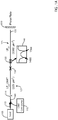
- FIG. 1A shows an example architecture for converting both a pump and a signal to a higher-order mode (HOM).
- FIG. 1A shows an embodiment using a cascaded Raman resonator (CRR) 115 as the pump source.
- the pump is multiplexed with the signal 110 at an input fiber 160 and the multiplexed light is launched into a gain-doped fiber 155, which is spliced 120 to the input fiber 160.
- CTR cascaded Raman resonator
- this configuration increases power efficiency, compared to conventional cladding pumping, by confining the pump light to the gain-doped area where the energy conversion occurs.
- the gain fiber 155 has a profile similar to that shown in FIG. 3 . Since one having ordinary skill in the art is familiar with these index profiles, FIG. 3 is not discussed in great detail herein. Suffice it to say that, in the embodiment of FIG. 1A , the core (d core ) and the inner cladding (d iclad ) are both gain-doped so that signals traveling through core and the inner cladding will be amplified.
- the mode converter 135 can be designed to have multiple peaks in conversion efficiency, thereby accommodating both the pump wavelength and the signal wavelength. Due to the high extinction of mode converters, light that is not resonant with the mode converter 135 will pass through the converter 135 with little attenuation or distortion.
- mode converter 135 can be designed to accommodate virtually any wavelength combinations. Since mode converters can be designed and fabricated with wideband operation, especially when operating at the turn-around point (TAP), if the pump and the signal wavelengths are within the conversion bandwidth, then both the signal and the pump will be converted to the same HOM as the light 145 continues to propagate down the gain-fiber 155.
- TAP turn-around point
- FIGS. 7A and 7B are diagrams showing near-field images of an example signal 610 and pump 720, respectively, which have both been converted to a HOM such that the intensity profile of the pump 720 substantially overlaps with the intensity profile of the signal 610. While FIGS. 7A and 7B show the HOM being the LP 06 mode, it should be appreciated that the pump and signal can be converted to other HOMs as desired or needed. Since, as shown in FIGS. 7A and 7B , the LP 06 pump 720 now overlaps with the LP 06 signal 610, the pump energy is more efficiently converted and there is less likelihood of ASE from the "dark" regions.
- multiple converters can be used to separately convert the pump and the signal.
- the signal and the pump need not be converted to the same HOM. Rather, the signal may be converted to one HOM while the pump is converted to another HOM.
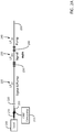
- FIG. 2A shows one embodiment in which the signal and the pump are converted to different HOMs, using two separate, serially-placed mode converters.
- the architecture comprises a signal source 205 that launches the signal 210 and a CRR 215 for the pump.
- the signal 210 and the pump are multiplexed onto an input fiber 255, which is spliced 220 to a gain-doped fiber 250.
- the gain-doped fiber of FIG. 2A has a gain-doped core and a gain-doped inner cladding.
- the multiplexed LP 01 light 225 travels some distance along the fiber 250, thereby allowing the signal to be amplified in the fundamental LP 01 mode.
- a signal mode converter converts the signal to LP 0m mode 235, while passing the pump with little-to-no distortion or attenuation.
- the resulting LP 06 signal will appear similar to that shown in FIG. 6A while the pump, which passes through the signal mode converter 230 without conversion, appears similar to that shown in FIG. 6B .
- the HOM signal 610 and the pump 620 pass through a pump mode converter 240, which is specifically configured to affect only the pump wavelength.
- the HOM signal 610 passes through the pump mode converter with little-to-no distortion or attenuation, while the LP 01 pump gets converted to a HOM.
- the signal mode converter 230 and the pump mode converter 240 are shown in FIG. 2A as being located serially along the gain fiber 250, it should be appreciated that, if the mode converters are constructed of LPGs or other comparable structures, the mode converters 230, 240 may be written at the same physical location in the gain fiber 250. Alternatively, the serial order of the mode converters can be rearranged without detrimental effect on the operation of the apparatus. Also, as shown in the embodiment of FIG. 2A , the HOM of the pump (n) need not be the same as the HOM of the signal (m).
- the pump mode converter 240 could be a wide-band converter constructed near the grating TAP to accommodate uncertainty or drift in pump wavelength or wavelength-multiplexing of several pumps.
- the signal mode converter 230 may be a narrow-band device to filter unwanted wavelength components. For this particular circumstance, it may be desirable to have the pump mode (n) be different from the signal mode (m).
- FIG. 1A To improve mode extinction, unwanted modes from splices and scattering can be stripped by strategically placing an optional HOM mode stripper 130 prior to the mode converter 135.
- FIG. 1B Another embodiment without the HOM mode stripper 130 is shown as FIG. 1B . Since the architecture of FIG. 1A is substantially similar to the architecture of FIG. 1B , with the exception of the mode stripper 130, a description of any duplicative items is omitted herein.
- the mode stripper 130 which is shown in FIG. 1A , can be fabricated as a short length of fiber, over which the coating is removed and the fiber is tapered or etched to cause light in the cladding to be stripped away. As such, only the light that is guided by the central core (which includes both the pump and signal) will be retained. In other words, the mode stripper 130 removes (or strips away) various undesired HOMs that may be present in the system, and the mode stripper 130 in combination with the mode converter 135 fulfills all filtering functions except that of in-band ASE in the same mode.
- light may reside in any number of HOMs that propagate backward (or counter to the signal). These unwanted HOMs can result from ASE, or stimulated Brllouin scattering (SBS) arising in the HOM gain fiber 155, or reflected light. Such backward propagating light will not be resonant with the mode converter 135 and will remain in the cladding, to be removed by the mode stripper 130.
- SBS stimulated Brllouin scattering
- Forward-propagating HOM light may originate at splices or from scattering in or before the segment on the signal-side of the mode stripper 130.
- the mode stripper 130 will also remove this forward-propagating HOM light.
- any ASE generated in the desired HOM, but out-of-band with the mode converter 135 will also not convert to the fundamental mode. As such, this out-of-band HOM will also be removed.
- backward-propagating in-band ASE that is generated in the LP 01 fundamental mode of the HOM section will convert to LP 07 and will also be removed by the mode stripper 130.
- the mode stripper 130 will remove all but the in-band HOM and the out-of-band fundamental mode.
- the in-band ASE is typically not a problem.
- the out-of-band fundamental mode may not be problematic because the pump profile will, by definition, match that of the signal. As such, much of the problematic portions of the light will be removed by the mode stripper 130, and any light that remains unaffected by the mode stripper 130 will likely be benign.
- FIG. 2A Given the functionality of the mode stripper 130 in FIG. 1A , similar improvements can be achieved in the embodiment of FIG. 2A by strategically placing an optional HOM mode stripper 130 prior to the mode converter 230. Such an embodiment, which includes the HOM mode stripper 130, is shown in FIG. 2B . Since the remaining architecture of FIG. 2B is substantially similar to the architecture of FIG. 2A , further discussion of other similar components in FIG. 2B is omitted here.
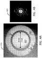
- FIG. 4A is a diagram showing a near-field image of a cross-section of an optical fiber
- FIG. 4B is a diagram showing a near-field image of an example signal that is transmitted along the fiber of FIG. 4A .
- conventional double-clad amplifiers including HOM amplifiers, are cladding pumped.
- These cladding-pumped amplifiers include a region that guides the signal (typically a core, which is gain-doped) and a region that guides the pump light (typically a cladding, which is not gain-doped).
- the cross-sectional area of the cladding is normally much greater than the cross-sectional area of the core. This difference in area accommodates low-brightness pumps that are used for high-power operation, which means that the rate of absorption of pump light is reduced by an amount that is roughly proportional to the ratio of the two areas. This results in a corresponding increase in the fiber length.
- LMA large-mode area
- the core has a relatively low numerical aperture (NA) to reduce the number of guided modes and maintain a large mode area.
- NA numerical aperture
- the pump guide e.g., cladding
- the signal guide e.g., core
- FIG. 4A shows a cross-sectional image 410 of a fiber (or waveguide) that can propagate HOM signals.
- the fiber comprises a central core (not visible in the image 410) and an inner cladding 430 that surrounds the core.
- Radially-exterior to the inner cladding 430 is a ring of air holes 440, which, in turn, is surrounded by a silica ring 450.
- a polymer layer surrounds the entire structure.
- the refractive index profile of such a fiber is shown in FIG. 3 .
- the inner cladding 430 is supported by a thin silica web, which defines the air holes.
- the thickness of the web is small enough to effectively confine the light to the inner cladding 430 and prevent leakage of light to the silica ring 450.
- the inner cladding 430 is a high NA guide (approximately 0.6 to 0.8), suitable for containing pump light.
- the NA can be significantly higher than conventional double-clad fiber, which is constructed of low-index polymer rather than air holes, the light-carrying capacity of the fiber in FIG. 4A is equivalent to a fiber that is about 50% larger in diameter.
- the pump guide can be pumped using free-space optics.
- FIG. 4B shows a near-field image 420 of an example HOM signal that is transmitted along the fiber of FIG. 4A .
- the scale of FIG. 4B is matched to the scale of FIG. 4A to show the correspondence between the diameter of the outer-most ring on the LP 06 HOM signal and the diameter of the inner cladding 430.
- the inner cladding 430 when gain-doped, is suitable for guiding HOMs.
- the pump and the signal can have high spatial overlap and be guided by the same gain-doped region 430 (core and inner cladding).
- the same waveguide confines both the signal and pump, even though the signal and pump may reside in different spatial modes.
- the intensity pattern on the HOM image 420 exhibits slight modulation due to the shape of the perimeter of the inner cladding 430.
- significant effort is expended to create a noncircular pump waveguide or induce mode distortion within the pump waveguide to more effectively couple pump light to the smaller gain (or core) region.
- the pump and signal are co-located, and, hence, the pump waveguide can be circular and undistorted.
- noncircular inner claddings can be configured.
- rectangular inner claddings can be used, due to their improved heat-transfer characteristics over thin dimensions.
- the core-pumping concept can be extended to polymer-clad fibers and glass-clad fibers.
- the trench area (d dd of FIG. 3 ) can be enlarged.
- the outer region (d oclad of FIG. 3 ) can be eliminated altogether.
- FIGS. 1 and 2 show various approaches to matching the intensity profile of the signal with the intensity profile of the pump.
- ASE from the "dark” regions can be reduced.
- Another alternative to reducing the ASE in these so-called “dark” regions is by selectively doping the gain-doped fiber so that the fiber regions that correspond to the "dark” regions of the signal will have no gain dopant. This is described in greater detail with reference to FIGS. 5A and 5B .
- FIG. 5A is a chart 500 showing an index profile 510 of an optical fiber and a corresponding HOM signal 520 that can be transmitted along the optical fiber.
- an LP 08 HOM signal 520 is carried along an inner cladding, which, in this particular embodiment, extends radially outward to approximately 40 micrometers. The "dark" regions correspond to the zero intensities on the HOM signal 520 plot.
- FIG. 5B is a chart showing the HOM signal 520 of FIG. 5A and a corresponding fiber-gain-doping profile 560.
- the fiber is doped with rare-earth (RE) dopants at distinct radial locations. Specifically, the location of the gain-dopants corresponds to each intensity peak of the LP 08 HOM signal 520.
- RE rare-earth
- FIG. 5B shows segmented doping of the fiber to correspond with the particular HOM signal that will be transmitted along that particular fiber.
- segmented doping as compared to simply converting the pump to a HOM, is a reduced flexibility in mode selection. Once a fiber has been gain-doped in specific regions, the intensity profile of the signal cannot be changed without destroying the signal's spatial correspondence with the gain-doped fiber profile. Additionally, any anomalous doping can result in imperfect overlap of the gain-doped region and the HOM signal. For this reason, it may be preferable to employ the approaches taught with reference to FIGS. 1 and 2 , rather than the segmented-doping approach of FIGS. 5A and 5B .
Description
- The present disclosure relates generally to optical fibers and, more particularly, to higher-order mode ("HOM") signal transmission in optical fibers.
- Ever since silica-based optical fibers have been used for high-power lasers and amplifiers, there have been ongoing efforts to increase the power of the signal that is transmitted through the fibers, and also to improve energy efficiency during signal amplification.
- In conventional laser pumping, energy is transferred from an external source to a gain-doped fiber (or other laser gain medium). That transferred energy is absorbed in the fiber, thereby producing excited states in the atoms within the fiber. At a given point, the number of particles in one excited state exceeds the number of particles in the ground state (or another less-excited state). In this condition, known as population inversion, stimulated emission can occur, and the fiber can act as a laser or an optical amplifier. Thus, when a signal is injected into the fiber, the pump energy is transferred from the gain medium to the injected signal, thereby amplifying the injected signal as it propagates along the fiber.
-
US 2005/153449 A1 discloses an amplifying optical fiber doped with a rare earth comprising a plurality of successive segments, presenting a monomode core and a multimode core, presenting at the periphery of the multimode core a peripheral segment of low index so as to increase the numerical aperture of the optical fiber. An outer cladding is situated at the periphery of the low index peripheral segment and the multimode core is at least in part above the outer cladding. The peripheral segment presents a decreasing gradient shape. -
EP 0 905 834 A2 - Efforts have been made to alter the profile for the injected signal. However, what has not been extensively studied is the effect of shaping the pump.
- Many aspects of the disclosure can be better understood with reference to the following drawings. The components in the drawings are not necessarily to scale, emphasis instead being placed upon clearly illustrating the principles of the present disclosure. Moreover, in the drawings, like reference numerals designate corresponding parts throughout the several views.
- FIG. IA is a schematic showing an example setup for converting both a pump and a signal to a higher-order mode (HOM).
- FIG. IB is a schematic showing another example setup for converting both a pump and a signal to a HOM.
-
FIG. 2A is a schematic showing a third example setup for converting both a pump and a signal to a HOM. -
FIG. 2B is a schematic showing a fourth example setup for converting both a pump and a signal to a HOM. -
FIG. 3 is a chart showing an example index profile of an optical fiber. -
FIG. 4A is a diagram showing a near-field image of a cross-section of an optical fiber. -
FIG. 4B is a diagram showing a near-field image of an example signal that is transmitted along the fiber ofFIG. 4A . -
FIG. 5A is a chart showing an index profile of an optical fiber and a corresponding HOM signal that can be transmitted along the optical fiber. -
FIG. 5B is a chart showing a signal profile of a HOM signal and a corresponding fiber-gain-doping profile. -
FIG. 6A is a diagram showing a near-field image of an example HOM signal. -
FIG. 6B is a diagram showing the pumped region that corresponds to the HOM signal ofFIG. 6A . -
FIG. 7A is a diagram showing a near-field image of an example HOM signal. -
FIG. 7B is a diagram showing the pumped region that corresponds to the HOM signal ofFIG. 7A . - Reference is now made in detail to the description of the embodiments as illustrated in the drawings. While several embodiments are described in connection with these drawings, there is no intent to limit the disclosure to the embodiment or embodiments disclosed herein. On the contrary, the intent is to cover all alternatives, modifications, and equivalents.
- As noted above, in conventional laser pumping, energy is transferred from an external source to a gain-doped fiber, thereby producing excited states in the atoms within the fiber. When population inversion is achieved, stimulated emission can occur, and the fiber can act as a laser or an optical amplifier. Thus, when a signal is injected into the fiber, the pump energy is transferred from the gain medium to the injected signal, thereby amplifying the injected signal as it propagates along the fiber.
- Rare-earth-doped amplifiers (e.g., those doped by Erbium (Er) or Ytterbium (Yb)), which produce high-power signals at around the 1.5-micrometer wavelength, are often cladding pumped, meaning that the pump is introduced into the cladding, which is not gain-doped. The pump light in the cladding, through various known reflective and refractive mechanisms, eventually enters the gain-doped region of the optical fiber, thereby resulting in population inversion in the gain-doped region.
- Unfortunately, for fibers that have a very small gain-doped cross-sectional area as compared to the cladding region, which is not gain-doped, the pump absorption length becomes large. The increase in absorption length results in lower excitation levels and, also, a compromised power efficiency.
- To remedy this problem, it is desirable to pump the core (or other gain-doped region), rather than the cladding, which is typically not gain-doped. However, suitable pump diodes, which can directly couple into the gain-doped region, do not have sufficient power. In some embodiments of the invention, as shown in
FIGS. 1 and2 herein, a cascaded Raman resonator (CRR) is used to pump the core (or other gain-doped region). It should be appreciated that the invention is not limited to the use of CRR. Rather, other fiber lasers can be used to pump the gain-doped region of the optical fiber. - Also shown in
FIGS. 1A ,1B ,2A , and2B are various approaches to further increase the conversion efficiency by suitably tailoring the pump to match the spatial intensity profile of the signal that is being amplified. By matching the spatial intensity profile of the pump to the spatial intensity profile of the signal, more effective energy extraction is achieved. The reason being that, when the pump energy is not transferred to the signal, this results in amplified spontaneous emissions (ASE), which, as is known in the art, is an undesired effect. - Referring now to the diagrams,
FIG. 1A shows an example architecture for converting both a pump and a signal to a higher-order mode (HOM). In particular,FIG. 1A shows an embodiment using a cascaded Raman resonator (CRR) 115 as the pump source. The pump is multiplexed with thesignal 110 at aninput fiber 160 and the multiplexed light is launched into a gain-dopedfiber 155, which is spliced 120 to theinput fiber 160. Since theCRR 115 pumps the gain-doped region at the launch end, rather than pumping the outer cladding (which is not gain-doped), this configuration increases power efficiency, compared to conventional cladding pumping, by confining the pump light to the gain-doped area where the energy conversion occurs. - In
FIG. 1A , amode converter 135, such as a long-period grating (LPG), is placed some distance along thegain fiber 155, allowing the signal to be amplified in the fundamental LP01 mode 125 before conversion to a higher-order mode (HOM) signal. Thegain fiber 155 has a profile similar to that shown inFIG. 3 . Since one having ordinary skill in the art is familiar with these index profiles,FIG. 3 is not discussed in great detail herein. Suffice it to say that, in the embodiment ofFIG. 1A , the core (dcore) and the inner cladding (diclad) are both gain-doped so that signals traveling through core and the inner cladding will be amplified. - Continuing with
FIG. 1A , themode converter 135 can be designed to have multiple peaks in conversion efficiency, thereby accommodating both the pump wavelength and the signal wavelength. Due to the high extinction of mode converters, light that is not resonant with themode converter 135 will pass through theconverter 135 with little attenuation or distortion. - While peaks are shown for wavelengths of 1480 and a range between 1500-1600 (shown here as 15xx)), it should be appreciated that the
mode converter 135 can be designed to accommodate virtually any wavelength combinations. Since mode converters can be designed and fabricated with wideband operation, especially when operating at the turn-around point (TAP), if the pump and the signal wavelengths are within the conversion bandwidth, then both the signal and the pump will be converted to the same HOM as the light 145 continues to propagate down the gain-fiber 155. -
FIGS. 7A and 7B are diagrams showing near-field images of anexample signal 610 and pump 720, respectively, which have both been converted to a HOM such that the intensity profile of thepump 720 substantially overlaps with the intensity profile of thesignal 610. WhileFIGS. 7A and 7B show the HOM being the LP06 mode, it should be appreciated that the pump and signal can be converted to other HOMs as desired or needed. Since, as shown inFIGS. 7A and 7B , the LP06 pump 720 now overlaps with the LP06 signal 610, the pump energy is more efficiently converted and there is less likelihood of ASE from the "dark" regions. - In other embodiments, multiple converters can be used to separately convert the pump and the signal. Also, for other embodiments, the signal and the pump need not be converted to the same HOM. Rather, the signal may be converted to one HOM while the pump is converted to another HOM.
FIG. 2A shows one embodiment in which the signal and the pump are converted to different HOMs, using two separate, serially-placed mode converters. - The architecture, as shown in
FIG. 2A , comprises asignal source 205 that launches thesignal 210 and aCRR 215 for the pump. Thesignal 210 and the pump are multiplexed onto aninput fiber 255, which is spliced 220 to a gain-dopedfiber 250. Similar to the embodiment described with reference toFIG. 1A , the gain-doped fiber ofFIG. 2A has a gain-doped core and a gain-doped inner cladding. - The multiplexed LP01 light 225 travels some distance along the
fiber 250, thereby allowing the signal to be amplified in the fundamental LP01 mode. At some point, a signal mode converter converts the signal to LP0m mode 235, while passing the pump with little-to-no distortion or attenuation.FIGS. 6A and 6B show a specific example where m = 6. Upon passing through thesignal mode converter 230, the resulting LP06 signal will appear similar to that shown inFIG. 6A while the pump, which passes through thesignal mode converter 230 without conversion, appears similar to that shown inFIG. 6B . - Subsequent to passing through the
signal mode converter 230, theHOM signal 610 and thepump 620 pass through apump mode converter 240, which is specifically configured to affect only the pump wavelength. As such, the HOM signal 610 passes through the pump mode converter with little-to-no distortion or attenuation, while the LP01 pump gets converted to a HOM. The convertedlight 245, which now includes the HOM signal and the HOM pump, continues to propagate down thegain fiber 250. - While the
signal mode converter 230 and thepump mode converter 240 are shown inFIG. 2A as being located serially along thegain fiber 250, it should be appreciated that, if the mode converters are constructed of LPGs or other comparable structures, themode converters gain fiber 250. Alternatively, the serial order of the mode converters can be rearranged without detrimental effect on the operation of the apparatus. Also, as shown in the embodiment ofFIG. 2A , the HOM of the pump (n) need not be the same as the HOM of the signal (m). - Reasons exist for converting the signal and the pump to different HOMs (i.e., m ≠ n). For example, the
pump mode converter 240 could be a wide-band converter constructed near the grating TAP to accommodate uncertainty or drift in pump wavelength or wavelength-multiplexing of several pumps. Thesignal mode converter 230 may be a narrow-band device to filter unwanted wavelength components. For this particular circumstance, it may be desirable to have the pump mode (n) be different from the signal mode (m). - Returning to the embodiment of
FIG. 1A , to improve mode extinction, unwanted modes from splices and scattering can be stripped by strategically placing an optionalHOM mode stripper 130 prior to themode converter 135. Another embodiment without theHOM mode stripper 130 is shown asFIG. 1B . Since the architecture ofFIG. 1A is substantially similar to the architecture ofFIG. 1B , with the exception of themode stripper 130, a description of any duplicative items is omitted herein. - Continuing, the
mode stripper 130, which is shown inFIG. 1A , can be fabricated as a short length of fiber, over which the coating is removed and the fiber is tapered or etched to cause light in the cladding to be stripped away. As such, only the light that is guided by the central core (which includes both the pump and signal) will be retained. In other words, themode stripper 130 removes (or strips away) various undesired HOMs that may be present in the system, and themode stripper 130 in combination with themode converter 135 fulfills all filtering functions except that of in-band ASE in the same mode. - For example, light may reside in any number of HOMs that propagate backward (or counter to the signal). These unwanted HOMs can result from ASE, or stimulated Brllouin scattering (SBS) arising in the
HOM gain fiber 155, or reflected light. Such backward propagating light will not be resonant with themode converter 135 and will remain in the cladding, to be removed by themode stripper 130. - Forward-propagating HOM light may originate at splices or from scattering in or before the segment on the signal-side of the
mode stripper 130. Themode stripper 130 will also remove this forward-propagating HOM light. - Additionally, any ASE generated in the desired HOM, but out-of-band with the
mode converter 135 will also not convert to the fundamental mode. As such, this out-of-band HOM will also be removed. - Also, backward-propagating in-band ASE that is generated in the LP01 fundamental mode of the HOM section will convert to LP07 and will also be removed by the
mode stripper 130. - In short, the
mode stripper 130 will remove all but the in-band HOM and the out-of-band fundamental mode. The in-band ASE, however, is typically not a problem. Also, the out-of-band fundamental mode may not be problematic because the pump profile will, by definition, match that of the signal. As such, much of the problematic portions of the light will be removed by themode stripper 130, and any light that remains unaffected by themode stripper 130 will likely be benign. - Given the functionality of the
mode stripper 130 inFIG. 1A , similar improvements can be achieved in the embodiment ofFIG. 2A by strategically placing an optionalHOM mode stripper 130 prior to themode converter 230. Such an embodiment, which includes theHOM mode stripper 130, is shown inFIG. 2B . Since the remaining architecture ofFIG. 2B is substantially similar to the architecture ofFIG. 2A , further discussion of other similar components inFIG. 2B is omitted here. - Since the
CRR -
FIG. 4A is a diagram showing a near-field image of a cross-section of an optical fiber, andFIG. 4B is a diagram showing a near-field image of an example signal that is transmitted along the fiber ofFIG. 4A . - As background, conventional double-clad amplifiers, including HOM amplifiers, are cladding pumped. These cladding-pumped amplifiers include a region that guides the signal (typically a core, which is gain-doped) and a region that guides the pump light (typically a cladding, which is not gain-doped). The cross-sectional area of the cladding is normally much greater than the cross-sectional area of the core. This difference in area accommodates low-brightness pumps that are used for high-power operation, which means that the rate of absorption of pump light is reduced by an amount that is roughly proportional to the ratio of the two areas. This results in a corresponding increase in the fiber length.
- Unfortunately, for high power amplifiers, this increase in length concomitantly increases the amount of undesired length-dependent nonlinear effects. For this reason, it is desirable to guide the pump in the same spatial region as the signal to increase the overlap.
- In conventional large-mode area (LMA) fibers with low-brightness pumps, this is typically not possible because the core has a relatively low numerical aperture (NA) to reduce the number of guided modes and maintain a large mode area. In such designs, the pump guide (e.g., cladding) has different characteristics, and therefore must be in a different spatial region that the signal guide (e.g., core).
- For HOM propagation, this need not be so. Because the mode is robustly guided and resistant to mode coupling, and because it can be excited with high extinction, the NA of the guide can be large. In fact, the pump guide and the HOM guide can be in the same region. Turning to the drawings,
FIG. 4A shows across-sectional image 410 of a fiber (or waveguide) that can propagate HOM signals. The fiber comprises a central core (not visible in the image 410) and aninner cladding 430 that surrounds the core. Radially-exterior to theinner cladding 430 is a ring ofair holes 440, which, in turn, is surrounded by asilica ring 450. While not shown, a polymer layer surrounds the entire structure. The refractive index profile of such a fiber is shown inFIG. 3 . - The
inner cladding 430 is supported by a thin silica web, which defines the air holes. The thickness of the web is small enough to effectively confine the light to theinner cladding 430 and prevent leakage of light to thesilica ring 450. Due to the large contrast in index between air and silica (shown as ΔNdd inFIG. 3 ), theinner cladding 430 is a high NA guide (approximately 0.6 to 0.8), suitable for containing pump light. - Moreover, since the NA can be significantly higher than conventional double-clad fiber, which is constructed of low-index polymer rather than air holes, the light-carrying capacity of the fiber in
FIG. 4A is equivalent to a fiber that is about 50% larger in diameter. For some HOM designs, the pump guide can be pumped using free-space optics. -
FIG. 4B shows a near-field image 420 of an example HOM signal that is transmitted along the fiber ofFIG. 4A . In particular, the scale ofFIG. 4B is matched to the scale ofFIG. 4A to show the correspondence between the diameter of the outer-most ring on the LP06 HOM signal and the diameter of theinner cladding 430. Given this correspondence, one can see that theinner cladding 430, when gain-doped, is suitable for guiding HOMs. As such, the pump and the signal can have high spatial overlap and be guided by the same gain-doped region 430 (core and inner cladding). In other words, the same waveguide confines both the signal and pump, even though the signal and pump may reside in different spatial modes. - Continuing with
FIG. 4B , the intensity pattern on theHOM image 420 exhibits slight modulation due to the shape of the perimeter of theinner cladding 430. In conventional double-clad fibers, significant effort is expended to create a noncircular pump waveguide or induce mode distortion within the pump waveguide to more effectively couple pump light to the smaller gain (or core) region. Unlike conventional double-clad fibers, inFIG. 4A , the pump and signal are co-located, and, hence, the pump waveguide can be circular and undistorted. - For other embodiments, noncircular inner claddings can be configured. For example, rectangular inner claddings can be used, due to their improved heat-transfer characteristics over thin dimensions.
- It is worthwhile to note that, while air-clad fibers are specifically shown in
FIG. 4A , the core-pumping concept can be extended to polymer-clad fibers and glass-clad fibers. For some embodiments that have a very deep trench (ΔNdd ofFIG. 3 is very large), the trench area (ddd ofFIG. 3 ) can be enlarged. As a consequence, the outer region (doclad ofFIG. 3 ) can be eliminated altogether. - As noted above, the embodiments of
FIGS. 1 and2 show various approaches to matching the intensity profile of the signal with the intensity profile of the pump. By matching the intensity profiles, ASE from the "dark" regions can be reduced. Another alternative to reducing the ASE in these so-called "dark" regions is by selectively doping the gain-doped fiber so that the fiber regions that correspond to the "dark" regions of the signal will have no gain dopant. This is described in greater detail with reference toFIGS. 5A and 5B . -
FIG. 5A is achart 500 showing anindex profile 510 of an optical fiber and acorresponding HOM signal 520 that can be transmitted along the optical fiber. As shown inFIG. 5A , an LP08 HOM signal 520 is carried along an inner cladding, which, in this particular embodiment, extends radially outward to approximately 40 micrometers. The "dark" regions correspond to the zero intensities on the HOM signal 520 plot. -
FIG. 5B is a chart showing the HOM signal 520 ofFIG. 5A and a corresponding fiber-gain-doping profile 560. As one can see, the fiber is doped with rare-earth (RE) dopants at distinct radial locations. Specifically, the location of the gain-dopants corresponds to each intensity peak of the LP08 HOM signal 520. Thus, unlike conventional gain-doped fibers, which largely have a uniform distribution of RE-dopants within the entire inner cladding, the embodiment ofFIG. 5B shows segmented doping of the fiber to correspond with the particular HOM signal that will be transmitted along that particular fiber. - One disadvantage of segmented doping, as compared to simply converting the pump to a HOM, is a reduced flexibility in mode selection. Once a fiber has been gain-doped in specific regions, the intensity profile of the signal cannot be changed without destroying the signal's spatial correspondence with the gain-doped fiber profile. Additionally, any anomalous doping can result in imperfect overlap of the gain-doped region and the HOM signal. For this reason, it may be preferable to employ the approaches taught with reference to
FIGS. 1 and2 , rather than the segmented-doping approach ofFIGS. 5A and 5B . - Although exemplary embodiments have been shown and described, it will be clear to those of ordinary skill in the art that a number of changes, modifications, or alterations to the disclosure as described may be made. For example, while specific HOMs have been shown in the drawings and described in detail, it should be appreciated that other mode orders (in addition to those that are expressly shown) can be used to accommodate various other design parameters. Additionally, while specific examples of doping profiles have been shown and described, it should be appreciated that these specific doping profiles may be altered to correspond, in varying degrees, to different HOM signals. All such changes, modifications, and alterations should therefore be seen as within the scope of the disclosure.
Claims (8)
- An optical fiber, comprising:a core having a first index of refraction;an inner cladding located radially-exterior to the core, the inner cladding having a second index of refraction, the second index of refraction being less than the first index of refraction and a trench located radially-exterior to the inner cladding, the trench having an index of refraction that is less than the second index of refraction; andsegmented doping of gain-dopants at distinct radial locations in the inner cladding at predefined locations, the predefined locations corresponding to concentric rings, each distinct radial location corresponding to an intensity peak of a higher-order mode (HOM) that will be transmitted along the optical fiber.
- The optical fiber of claim 1, the inner cladding being a waveguide having a high numerical aperture.
- The optical fiber of claim 1 the trench comprising air.
- The optical fiber of claim 1, the trench comprising a silica web.
- The optical fiber of claim 1, the trench comprising a low index polymer.
- The optical fiber of claim 1, the gain-dopants comprising rare-earth dopants.
- The optical fiber of claim 6, the rare-earth dopants comprising Erbium.
- The optical fiber of claim 6, the rare-earth dopants comprising Ytterbium.
Applications Claiming Priority (2)
| Application Number | Priority Date | Filing Date | Title |
|---|---|---|---|
| US88811407P | 2007-02-05 | 2007-02-05 | |
| PCT/US2008/053057 WO2008097977A2 (en) | 2007-02-05 | 2008-02-05 | Segmented gain-doping of an optical fiber |
Publications (3)
| Publication Number | Publication Date |
|---|---|
| EP2109788A2 EP2109788A2 (en) | 2009-10-21 |
| EP2109788A4 EP2109788A4 (en) | 2014-02-26 |
| EP2109788B1 true EP2109788B1 (en) | 2018-10-31 |
Family
ID=39682088
Family Applications (6)
| Application Number | Title | Priority Date | Filing Date |
|---|---|---|---|
| EP08729054.0A Active EP2109788B1 (en) | 2007-02-05 | 2008-02-05 | Segmented gain-doping of an optical fiber |
| EP08729061.5A Ceased EP2109789A4 (en) | 2007-02-05 | 2008-02-05 | Selectively pumping a gain-doped region of an optical fiber |
| EP08729045.8A Active EP2109790B1 (en) | 2007-02-05 | 2008-02-05 | Pumping in a higher-order mode that is different from a signal mode |
| EP08729039.1A Ceased EP2109787A4 (en) | 2007-02-05 | 2008-02-05 | Sequentially increasing effective area in higher-order mode (hom) signal propagation |
| EP08729063.1A Withdrawn EP2109785A4 (en) | 2007-02-05 | 2008-02-05 | Pumping in a higher- order mode that is substantially identical to a signal mode |
| EP08729033.4A Withdrawn EP2109786A4 (en) | 2007-02-05 | 2008-02-05 | Preventing dielectric breakdown in optical fibers |
Family Applications After (5)
| Application Number | Title | Priority Date | Filing Date |
|---|---|---|---|
| EP08729061.5A Ceased EP2109789A4 (en) | 2007-02-05 | 2008-02-05 | Selectively pumping a gain-doped region of an optical fiber |
| EP08729045.8A Active EP2109790B1 (en) | 2007-02-05 | 2008-02-05 | Pumping in a higher-order mode that is different from a signal mode |
| EP08729039.1A Ceased EP2109787A4 (en) | 2007-02-05 | 2008-02-05 | Sequentially increasing effective area in higher-order mode (hom) signal propagation |
| EP08729063.1A Withdrawn EP2109785A4 (en) | 2007-02-05 | 2008-02-05 | Pumping in a higher- order mode that is substantially identical to a signal mode |
| EP08729033.4A Withdrawn EP2109786A4 (en) | 2007-02-05 | 2008-02-05 | Preventing dielectric breakdown in optical fibers |
Country Status (6)
| Country | Link |
|---|---|
| US (6) | US8412015B2 (en) |
| EP (6) | EP2109788B1 (en) |
| JP (6) | JP5250564B2 (en) |
| CN (6) | CN101688984B (en) |
| AU (6) | AU2008213944B2 (en) |
| WO (6) | WO2008097988A2 (en) |
Families Citing this family (32)
| Publication number | Priority date | Publication date | Assignee | Title |
|---|---|---|---|---|
| AU2008213944B2 (en) * | 2007-02-05 | 2013-04-04 | Ofs Fitel, Llc | Sequentially increasing effective area in higher-order mode (HOM) signal propagation |
| JP5299959B2 (en) * | 2008-12-02 | 2013-09-25 | 国立大学法人東北大学 | Light beam amplification method and light beam amplification apparatus |
| US8428409B2 (en) * | 2009-05-11 | 2013-04-23 | Ofs Fitel, Llc | Filter fiber for use in Raman lasing applications and techniques for manufacturing same |
| FR2952243B1 (en) * | 2009-11-03 | 2012-05-11 | Univ Bordeaux 1 | OPTICAL SOURCE USING A DOPED FIBER, FIBER FOR SUCH AN OPTICAL SOURCE AND METHOD FOR MANUFACTURING SUCH A FIBER |
| US8498044B2 (en) * | 2009-12-22 | 2013-07-30 | Fujikura Ltd. | Amplification optical fiber, and optical fiber amplifier and resonator using the same |
| US9207395B2 (en) * | 2010-12-03 | 2015-12-08 | Ofs Fitel, Llc | Large mode area optical fibers with bend compensation |
| CN103547953A (en) * | 2011-02-24 | 2014-01-29 | Ofs飞泰尔公司 | Multicore fiber designs for spatial multiplexing |
| CN103460525B (en) * | 2011-03-31 | 2015-04-08 | 株式会社藤仓 | Amplification optical fibre, and optical fibre amplifier and resonator using same |
| JP5727305B2 (en) * | 2011-06-13 | 2015-06-03 | 日本電信電話株式会社 | Optical fiber amplifier |
| WO2013023193A1 (en) * | 2011-08-10 | 2013-02-14 | Ofs Fitel, Llc | Few moded fiber device employing mode conversion |
| US9502852B2 (en) * | 2011-10-06 | 2016-11-22 | Ofs Fitel, Llc | Fiber designs for wavelength tunable ultra-short pulse lasers |
| WO2013169626A1 (en) | 2012-05-05 | 2013-11-14 | Trustees Of Boston University | High-power fiber laser employing nonlinear wave mixing with higher-order modes |
| US9197030B2 (en) * | 2012-07-31 | 2015-11-24 | Corning Incorporated | Few mode rare earth doped optical fibers for optical amplifiers, and amplifiers using such fibers |
| US9093815B2 (en) * | 2012-08-29 | 2015-07-28 | Ofs Fitel, Llc | Optical fiber amplifier including rare-earth-doped cladding region |
| JP6059560B2 (en) * | 2013-03-04 | 2017-01-11 | 日本電信電話株式会社 | Multimode transmission optical amplifier |
| US9356416B2 (en) * | 2013-03-15 | 2016-05-31 | Ofs Fitel, Llc | Suppression of stimulated brillouin scattering in higher-order-mode optical fiber amplifiers |
| JP6109774B2 (en) * | 2013-03-15 | 2017-04-05 | オーエフエス ファイテル,エルエルシー | Suppression of stimulated Brillouin scattering in high-order mode fiber amplifiers. |
| US9537282B2 (en) * | 2013-09-20 | 2017-01-03 | Alcatel Lucent | System and method for a multi-mode pump in an optical amplifier |
| JP6265863B2 (en) * | 2014-08-12 | 2018-01-24 | 日本電信電話株式会社 | Optical amplifier and optical amplifier design method |
| JP6323913B2 (en) * | 2015-03-30 | 2018-05-16 | 日本電信電話株式会社 | Optical amplifier and transmission system |
| DE112016002585T5 (en) * | 2015-06-10 | 2018-05-24 | Furukawa Electric Co., Ltd. | Pulse laser device |
| US9871338B2 (en) * | 2015-12-31 | 2018-01-16 | Nlight, Inc. | Pump combiner for multi-clad fibers |
| JP6654064B2 (en) * | 2016-03-03 | 2020-02-26 | 日本電信電話株式会社 | Mode converter, optical amplifier and optical transmission system |
| US10261246B2 (en) * | 2016-12-14 | 2019-04-16 | Ofs Fitel, Llc | Polarization-maintaining fiber device supporting propagation in large mode field diameters |
| WO2019026906A1 (en) * | 2017-08-01 | 2019-02-07 | 日本電信電話株式会社 | Optical fiber and optical transmission system |
| CN107749557B (en) * | 2017-11-08 | 2019-08-30 | 合肥工业大学 | The middle tunable IR Fiber-optic parameter oscillator of high-order mode signal injection |
| JP2019145895A (en) * | 2018-02-16 | 2019-08-29 | 株式会社村田製作所 | Acoustic wave device, multiplexer, high frequency front end circuit and communication apparatus |
| CN109412000B (en) | 2018-12-13 | 2020-02-07 | 华南理工大学 | Ultra-wideband high-gain optical fiber and device preparation technology |
| CN113227847A (en) * | 2018-12-28 | 2021-08-06 | 恩耐公司 | Optical fiber apparatus and method for directing Stimulated Raman Scattering (SRS) light out of a core and into a cladding |
| EP3903133A4 (en) * | 2018-12-28 | 2022-09-21 | NLIGHT, Inc. | Optical fiber devices and methods for suppressing stimulated raman scattering (srs) |
| JP6785901B2 (en) * | 2019-02-21 | 2020-11-18 | 株式会社フジクラ | Filter device, laser device |
| CN113189696A (en) * | 2020-01-14 | 2021-07-30 | 华为技术有限公司 | Optical fiber filter and optical fiber amplifier |
Citations (1)
| Publication number | Priority date | Publication date | Assignee | Title |
|---|---|---|---|---|
| US5966481A (en) * | 1997-12-23 | 1999-10-12 | Northern Telecom Limited | Optically pumped optical waveguide amplifier |
Family Cites Families (92)
| Publication number | Priority date | Publication date | Assignee | Title |
|---|---|---|---|---|
| US3790902A (en) * | 1972-09-05 | 1974-02-05 | Bell Telephone Labor Inc | Fundamental transverse mode operation in solid state lasers |
| US3875422A (en) * | 1974-07-24 | 1975-04-01 | Bell Telephone Labor Inc | Four photon parametric amplification in glassy optical waveguides |
| US5363463A (en) * | 1982-08-06 | 1994-11-08 | Kleinerman Marcos Y | Remote sensing of physical variables with fiber optic systems |
| US4741586A (en) * | 1987-02-20 | 1988-05-03 | The Board Of Trustees Of The Leland Stanford Junior University | Dynamic coupler using two-mode optical waveguides |
| GB8724736D0 (en) * | 1987-10-22 | 1987-11-25 | British Telecomm | Optical fibre |
| FR2638854B1 (en) * | 1988-11-10 | 1992-09-04 | Comp Generale Electricite | DOPED FIBER OPTIC LASER AMPLIFIER |
| GB2239983A (en) * | 1989-12-22 | 1991-07-17 | Univ Southampton | Optical fibre laser |
| US5185827A (en) * | 1991-09-26 | 1993-02-09 | At&T Bell Laboratories | Apparatus for compensating chromatic dispersion in optical fibers |
| JP2713031B2 (en) * | 1992-07-17 | 1998-02-16 | 日立電線株式会社 | Rare earth doped multi-core fiber and optical amplifier using the same |
| US6373868B1 (en) * | 1993-05-28 | 2002-04-16 | Tong Zhang | Single-mode operation and frequency conversions for diode-pumped solid-state lasers |
| US5638388A (en) * | 1995-02-04 | 1997-06-10 | Spectra-Physics Lasers, Inc. | Diode pumped, multi axial mode intracavity doubled laser |
| US6018533A (en) * | 1995-04-21 | 2000-01-25 | Ceramoptec Industries, Inc. | Optical fiber and integrated optic lasers with enhanced output power |
| US5703978A (en) * | 1995-10-04 | 1997-12-30 | Lucent Technologies Inc. | Temperature insensitive long-period fiber grating devices |
| US5708669A (en) * | 1996-09-24 | 1998-01-13 | Lucent Technologies Inc. | Article comprising a cladding-pumped optical fiber laser |
| US5877890A (en) * | 1996-10-30 | 1999-03-02 | Rutgers, The State University Of New Jersey | Optical-fiber amplifier having high-saturation output |
| GB9625231D0 (en) * | 1996-12-04 | 1997-01-22 | Univ Southampton | Optical amplifiers & lasers |
| US5880877A (en) * | 1997-01-28 | 1999-03-09 | Imra America, Inc. | Apparatus and method for the generation of high-power femtosecond pulses from a fiber amplifier |
| US5907647A (en) * | 1997-02-18 | 1999-05-25 | Lucent Technologies Inc. | Long-period grating switches and devices using them |
| US5815518A (en) * | 1997-06-06 | 1998-09-29 | Lucent Technologies Inc. | Article comprising a cascaded raman fiber laser |
| US5907652A (en) * | 1997-09-11 | 1999-05-25 | Lucent Technologies Inc. | Article comprising an air-clad optical fiber |
| US6011886A (en) * | 1997-10-16 | 2000-01-04 | Lucent Technologies Inc. | Recoatable temperature-insensitive long-period gratings |
| JP4075113B2 (en) * | 1997-11-07 | 2008-04-16 | 住友電気工業株式会社 | Optical fiber amplifier and erbium-doped optical fiber |
| US6404951B2 (en) * | 1998-03-26 | 2002-06-11 | Lasercomm Inc. | Transverse spatial mode transformer for optical communication |
| US6084996A (en) * | 1998-04-01 | 2000-07-04 | Lucent Technologies, Inc. | Broadband long-period gratings |
| EP1108235A4 (en) * | 1998-06-04 | 2005-11-09 | California Inst Of Techn | Optical devices based on energy transfer between different modes in optical waveguide |
| JP2002519729A (en) * | 1998-06-29 | 2002-07-02 | コーニング インコーポレイテッド | Monolithic coaxial device |
| US6163552A (en) * | 1998-08-14 | 2000-12-19 | Lucent Technologies Inc. | Article comprising an optical fiber cascaded Raman resonator |
| FR2784197B1 (en) * | 1998-10-05 | 2000-12-15 | Cit Alcatel | MONOMODE FIBER OPTICAL WITH OFFSET DISPERSION WITH LARGE EFFECTIVE AREA |
| US6275512B1 (en) * | 1998-11-25 | 2001-08-14 | Imra America, Inc. | Mode-locked multimode fiber laser pulse source |
| US6360045B1 (en) * | 1999-02-23 | 2002-03-19 | Lasercomm Inc. | High order spatial mode transmission system |
| US6327403B1 (en) * | 1999-06-10 | 2001-12-04 | Lasercomm Inc. | Reducing mode interference in transmission of LP02 Mode in optical fibers |
| CN1190677C (en) * | 1999-09-02 | 2005-02-23 | 国际商业机器公司 | Widening of array waveguide raster pass-band response |
| US20020164140A1 (en) * | 2000-01-12 | 2002-11-07 | Michael Lysiansky | Few-mode fiber profile |
| US6453102B1 (en) * | 2000-02-07 | 2002-09-17 | Corning Incorporated | Dispersion compensating module and mode converter, coupler and dispersion compensating optical waveguide therein |
| US20010043388A1 (en) * | 2000-02-29 | 2001-11-22 | Yochay Danziger | High order mode erbium-doped fiber amplifier |
| JP2001267665A (en) * | 2000-03-16 | 2001-09-28 | Sumitomo Electric Ind Ltd | Optical fiber for light amplification and optical fiber amplifier and optical fiber laser oscillator |
| US6483974B1 (en) * | 2000-10-24 | 2002-11-19 | Jds Uniphase Corporation | Optical fiber with improved cross-sectional profile and optical gain media using same |
| AUPR196400A0 (en) * | 2000-12-07 | 2001-01-04 | Defence Science And Technology Organisation | Rare-earth-doped waveguide |
| US6724964B2 (en) * | 2001-01-30 | 2004-04-20 | Lasercomm Inc. | Optical waveguide exhibiting strongly positive dispersion, and system utilizing same |
| US6807338B2 (en) * | 2001-03-12 | 2004-10-19 | Fitel Usa Corp. | Multiwavelength cascaded raman resonator |
| FR2822243B1 (en) | 2001-03-16 | 2003-06-20 | Cit Alcatel | DUAL SHEATH PHOTONIC OPTICAL FIBER |
| EP1393105A4 (en) * | 2001-04-12 | 2006-03-22 | Omniguide Inc | High index-contrast fiber waveguides and applications |
| US6483975B1 (en) * | 2001-04-27 | 2002-11-19 | Fitel Usa Corp. | Positive dispersion optical fiber having large effective area |
| DE60107666T2 (en) * | 2001-06-11 | 2005-10-06 | Avanex Corp., Fremont | An optical waveguide and manufacturing method for an asymmetric optical filter device |
| JP3875597B2 (en) * | 2001-06-27 | 2007-01-31 | フルカワ エレクトリック ノース アメリカ インコーポレーテッド | Optical bandpass filter using a long-period grating. |
| US6845194B2 (en) * | 2001-06-27 | 2005-01-18 | Furukawa Electric North America Inc. | Optical bandpass filter using long period gratings |
| EP1421419B1 (en) * | 2001-07-12 | 2007-09-12 | OCG Technology Licensing, LLC | Optical fiber |
| ATE251352T1 (en) * | 2001-07-23 | 2003-10-15 | Cit Alcatel | OPTICAL FIBER AMPLIFIER AND COMMUNICATIONS SYSTEM USING THE SAME |
| JP2003114350A (en) * | 2001-07-31 | 2003-04-18 | Furukawa Electric Co Ltd:The | Optical fiber, optical fiber component, and optical transmission method |
| US6480659B1 (en) * | 2001-11-14 | 2002-11-12 | Rayteq Photonic Solutions Ltd. | Optic fiber structure for efficient use of optical pump energy in three-level rare-earth doped fiber laser |
| JP2003158324A (en) * | 2001-11-26 | 2003-05-30 | Nikon Corp | Light source and light irradiator |
| EP1318579A1 (en) * | 2001-12-10 | 2003-06-11 | Corning Incorporated | Multi-wavelength raman laser |
| JP4007812B2 (en) * | 2002-01-18 | 2007-11-14 | 富士通株式会社 | Raman amplifier, wavelength division multiplexing optical communication system, and control method of Raman amplification |
| FR2838261B1 (en) * | 2002-04-05 | 2004-07-09 | Cit Alcatel | DISPERSION COMPENSATION FIBER USING HIGHER ORDER MODE |
| CA2486297A1 (en) * | 2002-05-17 | 2003-11-27 | The Board Of Trustees Of The Leland Stanford Junior University | Double-clad fiber lasers and amplifiers having long-period fiber gratings |
| US7321705B2 (en) * | 2002-05-28 | 2008-01-22 | Optun (Bvi) Ltd. | Method and device for optical switching and variable optical attenuation |
| US6937788B2 (en) * | 2002-09-04 | 2005-08-30 | Furukawa Electric North America | Adjustable dispersion compensator with few mode fibers and switchable mode converters |
| US6768835B2 (en) * | 2002-09-04 | 2004-07-27 | Fitel Usa Corp | Tunable mode-converters using few mode fibers |
| WO2004049012A2 (en) * | 2002-10-16 | 2004-06-10 | Lake Shore Cryotronics, Inc. | Method of manufacturing a spectral filter for green and longer wavelengths |
| WO2004054050A1 (en) * | 2002-12-10 | 2004-06-24 | Nikon Corporation | Ultraviolet light source, phototherapy apparatus using ultraviolet light source, and exposure system using ultraviolet light source |
| WO2004066458A2 (en) | 2003-01-24 | 2004-08-05 | Trumpf, Inc. | Fiber laser |
| FR2854249B1 (en) * | 2003-04-25 | 2005-07-08 | Cit Alcatel | DEVICE AND METHOD FOR SIGNAL PROPAGATION MODE TRANSFORMATION BY INTERFERENCE |
| FR2855619B1 (en) * | 2003-05-27 | 2005-07-22 | Cit Alcatel | OPTICAL FIBER FOR AMPLIFICATION OR LASER EMISSION |
| JP4047232B2 (en) * | 2003-06-18 | 2008-02-13 | 株式会社フジクラ | Mode converter for high-order mode fiber |
| US7120340B2 (en) * | 2003-06-19 | 2006-10-10 | Corning Incorporated | Single polarization optical fiber laser and amplifier |
| JP4152813B2 (en) * | 2003-06-24 | 2008-09-17 | 株式会社フジクラ | Mode converter fiber, mode converter, optical transmission line |
| JP2005084386A (en) * | 2003-09-09 | 2005-03-31 | Mitsubishi Cable Ind Ltd | Double clad fiber and optical device provided with the same, and optical amplifier |
| FR2860598B1 (en) * | 2003-10-03 | 2005-12-16 | Cit Alcatel | SUPRESSION OF MODE (S) FOR PROPAGATION OF UNDESIRABLE SIGNALS BEFORE A MODE CONVERTER |
| JP2005129863A (en) * | 2003-10-27 | 2005-05-19 | Mitsubishi Cable Ind Ltd | Exciting light incident method to double cladding fiber |
| US20050123241A1 (en) * | 2003-12-03 | 2005-06-09 | Moti Margalit | Polarization independent frequency selective optical coupler |
| US7343098B2 (en) * | 2003-12-17 | 2008-03-11 | The Boeing Company | Fiber optic phased array and associated method for accommodating atmospheric perturbations with phase and amplitude control |
| FR2864254B1 (en) * | 2003-12-23 | 2006-03-03 | Cit Alcatel | HOM MULTIMODE OPTICAL FIBER WITH DISPERSION MANAGEMENT |
| US7724422B2 (en) * | 2004-01-30 | 2010-05-25 | Nufern | Method and apparatus for providing light having a selected polarization with an optical fiber |
| US7742512B2 (en) * | 2004-02-02 | 2010-06-22 | Raytheon Company | Scalable laser with robust phase locking |
| FR2867865B1 (en) * | 2004-03-16 | 2008-05-30 | Cit Alcatel | CHROMATIC BAND DISPERSION COMPENSATION OPTICAL FIBER USING HIGHER ORDER MODE |
| US7082243B2 (en) * | 2004-04-05 | 2006-07-25 | Corning Incorporated | Large effective area high SBS threshold optical fiber |
| US6950578B1 (en) * | 2004-05-28 | 2005-09-27 | Fitel Usa Corp. | Highly index-sensitive optical devices including long period fiber gratings |
| US7424193B2 (en) * | 2004-07-14 | 2008-09-09 | The Regents Of The University Of Michigan | Composite waveguide |
| WO2006010798A1 (en) * | 2004-07-26 | 2006-02-02 | Photonium Oy | Multimode optical fiber with low differential mode delay |
| US7177510B2 (en) * | 2004-08-09 | 2007-02-13 | Fitel Usa Corp. | Polarization insensitive microbend fiber gratings and devices using the same |
| FR2875016B1 (en) * | 2004-09-08 | 2006-11-24 | Cit Alcatel | MODE CONVERTER |
| JP4561314B2 (en) * | 2004-10-28 | 2010-10-13 | 日立電線株式会社 | Optical fiber for fiber laser, fiber laser, and laser oscillation method |
| US7171074B2 (en) * | 2004-11-16 | 2007-01-30 | Furakawa Electric North America Inc. | Large mode area fibers using higher order modes |
| GB0500277D0 (en) * | 2005-01-07 | 2005-02-16 | Southampton Photonics Ltd | Apparatus for propagating optical radiation |
| US20060233554A1 (en) | 2005-04-14 | 2006-10-19 | Siddharth Ramachandran | Optical fiber systems for delivering short high power pulses |
| US7200308B2 (en) * | 2005-06-28 | 2007-04-03 | California Institute Of Technology | Frequency conversion with nonlinear optical polymers and high index contrast waveguides |
| US7228029B1 (en) * | 2005-09-20 | 2007-06-05 | Furukawa Electric North America Inc. | Short pulse lasers using large mode area fibers and higher order modes |
| FR2893149B1 (en) * | 2005-11-10 | 2008-01-11 | Draka Comteq France | OPTICAL FIBER MONOMODE. |
| US20070206910A1 (en) | 2006-03-04 | 2007-09-06 | Siddharth Ramachandran | Optical fibers and optical fiber devices with total dispersion greater than material dispersion |
| US7257293B1 (en) | 2006-07-14 | 2007-08-14 | Furukawa Electric North America, Inc. | Fiber structure with improved bend resistance |
| US7356232B1 (en) * | 2006-08-01 | 2008-04-08 | Furukawa Electric North America | Optical fibers for high power applications |
| AU2008213944B2 (en) | 2007-02-05 | 2013-04-04 | Ofs Fitel, Llc | Sequentially increasing effective area in higher-order mode (HOM) signal propagation |
-
2008
- 2008-02-05 AU AU2008213944A patent/AU2008213944B2/en active Active
- 2008-02-05 WO PCT/US2008/053071 patent/WO2008097988A2/en active Application Filing
- 2008-02-05 JP JP2009549199A patent/JP5250564B2/en active Active
- 2008-02-05 CN CN2008800041362A patent/CN101688984B/en active Active
- 2008-02-05 CN CN200880004135A patent/CN101702959A/en active Pending
- 2008-02-05 WO PCT/US2008/053048 patent/WO2008097968A2/en active Application Filing
- 2008-02-05 EP EP08729054.0A patent/EP2109788B1/en active Active
- 2008-02-05 EP EP08729061.5A patent/EP2109789A4/en not_active Ceased
- 2008-02-05 EP EP08729045.8A patent/EP2109790B1/en active Active
- 2008-02-05 US US12/525,122 patent/US8412015B2/en active Active
- 2008-02-05 EP EP08729039.1A patent/EP2109787A4/en not_active Ceased
- 2008-02-05 CN CN2008800041663A patent/CN101688950B/en active Active
- 2008-02-05 WO PCT/US2008/053057 patent/WO2008097977A2/en active Application Filing
- 2008-02-05 JP JP2009549207A patent/JP2010518634A/en active Pending
- 2008-02-05 US US12/525,138 patent/US20100027938A1/en not_active Abandoned
- 2008-02-05 JP JP2009549198A patent/JP5276021B2/en active Active
- 2008-02-05 JP JP2009549201A patent/JP2010518632A/en active Pending
- 2008-02-05 US US12/525,124 patent/US8520299B2/en active Active
- 2008-02-05 AU AU2008213822A patent/AU2008213822B2/en not_active Ceased
- 2008-02-05 JP JP2009549206A patent/JP5484073B2/en active Active
- 2008-02-05 US US12/523,348 patent/US8000570B2/en active Active
- 2008-02-05 CN CN200880004176.7A patent/CN101688944B/en active Active
- 2008-02-05 EP EP08729063.1A patent/EP2109785A4/en not_active Withdrawn
- 2008-02-05 WO PCT/US2008/053036 patent/WO2008097958A1/en active Application Filing
- 2008-02-05 JP JP2009549204A patent/JP5250565B2/en active Active
- 2008-02-05 WO PCT/US2008/053042 patent/WO2008097963A1/en active Application Filing
- 2008-02-05 EP EP08729033.4A patent/EP2109786A4/en not_active Withdrawn
- 2008-02-05 US US12/525,339 patent/US7925128B2/en active Active
- 2008-02-05 AU AU2008213831A patent/AU2008213831B2/en not_active Ceased
- 2008-02-05 CN CN2008800041502A patent/CN101688949B/en active Active
- 2008-02-05 AU AU2008213949A patent/AU2008213949B2/en not_active Ceased
- 2008-02-05 WO PCT/US2008/053069 patent/WO2008097986A2/en active Application Filing
- 2008-02-05 AU AU2008213833A patent/AU2008213833B2/en not_active Ceased
- 2008-02-05 CN CN2008800041165A patent/CN101688948B/en active Active
- 2008-02-05 AU AU2008213939A patent/AU2008213939B2/en not_active Ceased
- 2008-02-05 US US12/525,332 patent/US8103142B2/en active Active
Patent Citations (1)
| Publication number | Priority date | Publication date | Assignee | Title |
|---|---|---|---|---|
| US5966481A (en) * | 1997-12-23 | 1999-10-12 | Northern Telecom Limited | Optically pumped optical waveguide amplifier |
Also Published As
Similar Documents
| Publication | Publication Date | Title |
|---|---|---|
| EP2109788B1 (en) | Segmented gain-doping of an optical fiber | |
| US8045259B2 (en) | Active optical fibers with wavelength-selective filtering mechanism, method of production and their use | |
| US9164230B2 (en) | High-power double-cladding-pumped (DC) erbium-doped fiber amplifier (EDFA) | |
| WO2003055017A1 (en) | Raman amplification using a microstructured fiber | |
| WO2010057288A1 (en) | Pump combiner including a multi-clad waveguide | |
| US7120339B2 (en) | Polarization-dependent optical fibre amplifier |
Legal Events
| Date | Code | Title | Description |
|---|---|---|---|
| PUAI | Public reference made under article 153(3) epc to a published international application that has entered the european phase |
Free format text: ORIGINAL CODE: 0009012 |
|
| 17P | Request for examination filed |
Effective date: 20090707 |
|
| AK | Designated contracting states |
Kind code of ref document: A2 Designated state(s): AT BE BG CH CY CZ DE DK EE ES FI FR GB GR HR HU IE IS IT LI LT LU LV MC MT NL NO PL PT RO SE SI SK TR |
|
| DAX | Request for extension of the european patent (deleted) | ||
| A4 | Supplementary search report drawn up and despatched |
Effective date: 20140124 |
|
| RIC1 | Information provided on ipc code assigned before grant |
Ipc: G02B 6/036 20060101ALI20140120BHEP Ipc: G02B 6/02 20060101AFI20140120BHEP Ipc: H01S 3/067 20060101ALN20140120BHEP Ipc: H01S 3/094 20060101ALN20140120BHEP |
|
| STAA | Information on the status of an ep patent application or granted ep patent |
Free format text: STATUS: EXAMINATION IS IN PROGRESS |
|
| 17Q | First examination report despatched |
Effective date: 20170224 |
|
| REG | Reference to a national code |
Ref country code: DE Ref legal event code: R079 Ref document number: 602008057670 Country of ref document: DE Free format text: PREVIOUS MAIN CLASS: G02B0006260000 Ipc: G02B0006020000 |
|
| RIC1 | Information provided on ipc code assigned before grant |
Ipc: G02B 6/14 20060101ALI20180126BHEP Ipc: G02B 6/036 20060101ALI20180126BHEP Ipc: H01S 3/094 20060101ALN20180126BHEP Ipc: G02B 6/02 20060101AFI20180126BHEP Ipc: H01S 3/067 20060101ALN20180126BHEP Ipc: G02B 6/42 20060101ALN20180126BHEP |
|
| GRAP | Despatch of communication of intention to grant a patent |
Free format text: ORIGINAL CODE: EPIDOSNIGR1 |
|
| STAA | Information on the status of an ep patent application or granted ep patent |
Free format text: STATUS: GRANT OF PATENT IS INTENDED |
|
| INTG | Intention to grant announced |
Effective date: 20180514 |
|
| GRAS | Grant fee paid |
Free format text: ORIGINAL CODE: EPIDOSNIGR3 |
|
| GRAA | (expected) grant |
Free format text: ORIGINAL CODE: 0009210 |
|
| STAA | Information on the status of an ep patent application or granted ep patent |
Free format text: STATUS: THE PATENT HAS BEEN GRANTED |
|
| AK | Designated contracting states |
Kind code of ref document: B1 Designated state(s): AT BE BG CH CY CZ DE DK EE ES FI FR GB GR HR HU IE IS IT LI LT LU LV MC MT NL NO PL PT RO SE SI SK TR |
|
| REG | Reference to a national code |
Ref country code: CH Ref legal event code: EP Ref country code: GB Ref legal event code: FG4D |
|
| REG | Reference to a national code |
Ref country code: AT Ref legal event code: REF Ref document number: 1060072 Country of ref document: AT Kind code of ref document: T Effective date: 20181115 |
|
| REG | Reference to a national code |
Ref country code: DE Ref legal event code: R096 Ref document number: 602008057670 Country of ref document: DE |
|
| REG | Reference to a national code |
Ref country code: IE Ref legal event code: FG4D |
|
| REG | Reference to a national code |
Ref country code: NL Ref legal event code: MP Effective date: 20181031 |
|
| REG | Reference to a national code |
Ref country code: LT Ref legal event code: MG4D |
|
| REG | Reference to a national code |
Ref country code: AT Ref legal event code: MK05 Ref document number: 1060072 Country of ref document: AT Kind code of ref document: T Effective date: 20181031 |
|
| PG25 | Lapsed in a contracting state [announced via postgrant information from national office to epo] |
Ref country code: HR Free format text: LAPSE BECAUSE OF FAILURE TO SUBMIT A TRANSLATION OF THE DESCRIPTION OR TO PAY THE FEE WITHIN THE PRESCRIBED TIME-LIMIT Effective date: 20181031 Ref country code: AT Free format text: LAPSE BECAUSE OF FAILURE TO SUBMIT A TRANSLATION OF THE DESCRIPTION OR TO PAY THE FEE WITHIN THE PRESCRIBED TIME-LIMIT Effective date: 20181031 Ref country code: PL Free format text: LAPSE BECAUSE OF FAILURE TO SUBMIT A TRANSLATION OF THE DESCRIPTION OR TO PAY THE FEE WITHIN THE PRESCRIBED TIME-LIMIT Effective date: 20181031 Ref country code: BG Free format text: LAPSE BECAUSE OF FAILURE TO SUBMIT A TRANSLATION OF THE DESCRIPTION OR TO PAY THE FEE WITHIN THE PRESCRIBED TIME-LIMIT Effective date: 20190131 Ref country code: LT Free format text: LAPSE BECAUSE OF FAILURE TO SUBMIT A TRANSLATION OF THE DESCRIPTION OR TO PAY THE FEE WITHIN THE PRESCRIBED TIME-LIMIT Effective date: 20181031 Ref country code: ES Free format text: LAPSE BECAUSE OF FAILURE TO SUBMIT A TRANSLATION OF THE DESCRIPTION OR TO PAY THE FEE WITHIN THE PRESCRIBED TIME-LIMIT Effective date: 20181031 Ref country code: IS Free format text: LAPSE BECAUSE OF FAILURE TO SUBMIT A TRANSLATION OF THE DESCRIPTION OR TO PAY THE FEE WITHIN THE PRESCRIBED TIME-LIMIT Effective date: 20190228 Ref country code: NO Free format text: LAPSE BECAUSE OF FAILURE TO SUBMIT A TRANSLATION OF THE DESCRIPTION OR TO PAY THE FEE WITHIN THE PRESCRIBED TIME-LIMIT Effective date: 20190131 Ref country code: FI Free format text: LAPSE BECAUSE OF FAILURE TO SUBMIT A TRANSLATION OF THE DESCRIPTION OR TO PAY THE FEE WITHIN THE PRESCRIBED TIME-LIMIT Effective date: 20181031 Ref country code: LV Free format text: LAPSE BECAUSE OF FAILURE TO SUBMIT A TRANSLATION OF THE DESCRIPTION OR TO PAY THE FEE WITHIN THE PRESCRIBED TIME-LIMIT Effective date: 20181031 |
|
| PG25 | Lapsed in a contracting state [announced via postgrant information from national office to epo] |
Ref country code: GR Free format text: LAPSE BECAUSE OF FAILURE TO SUBMIT A TRANSLATION OF THE DESCRIPTION OR TO PAY THE FEE WITHIN THE PRESCRIBED TIME-LIMIT Effective date: 20190201 Ref country code: SE Free format text: LAPSE BECAUSE OF FAILURE TO SUBMIT A TRANSLATION OF THE DESCRIPTION OR TO PAY THE FEE WITHIN THE PRESCRIBED TIME-LIMIT Effective date: 20181031 Ref country code: NL Free format text: LAPSE BECAUSE OF FAILURE TO SUBMIT A TRANSLATION OF THE DESCRIPTION OR TO PAY THE FEE WITHIN THE PRESCRIBED TIME-LIMIT Effective date: 20181031 Ref country code: PT Free format text: LAPSE BECAUSE OF FAILURE TO SUBMIT A TRANSLATION OF THE DESCRIPTION OR TO PAY THE FEE WITHIN THE PRESCRIBED TIME-LIMIT Effective date: 20190301 |
|
| PG25 | Lapsed in a contracting state [announced via postgrant information from national office to epo] |
Ref country code: DK Free format text: LAPSE BECAUSE OF FAILURE TO SUBMIT A TRANSLATION OF THE DESCRIPTION OR TO PAY THE FEE WITHIN THE PRESCRIBED TIME-LIMIT Effective date: 20181031 Ref country code: CZ Free format text: LAPSE BECAUSE OF FAILURE TO SUBMIT A TRANSLATION OF THE DESCRIPTION OR TO PAY THE FEE WITHIN THE PRESCRIBED TIME-LIMIT Effective date: 20181031 Ref country code: IT Free format text: LAPSE BECAUSE OF FAILURE TO SUBMIT A TRANSLATION OF THE DESCRIPTION OR TO PAY THE FEE WITHIN THE PRESCRIBED TIME-LIMIT Effective date: 20181031 |
|
| REG | Reference to a national code |
Ref country code: DE Ref legal event code: R097 Ref document number: 602008057670 Country of ref document: DE |
|
| PG25 | Lapsed in a contracting state [announced via postgrant information from national office to epo] |
Ref country code: RO Free format text: LAPSE BECAUSE OF FAILURE TO SUBMIT A TRANSLATION OF THE DESCRIPTION OR TO PAY THE FEE WITHIN THE PRESCRIBED TIME-LIMIT Effective date: 20181031 Ref country code: EE Free format text: LAPSE BECAUSE OF FAILURE TO SUBMIT A TRANSLATION OF THE DESCRIPTION OR TO PAY THE FEE WITHIN THE PRESCRIBED TIME-LIMIT Effective date: 20181031 Ref country code: SK Free format text: LAPSE BECAUSE OF FAILURE TO SUBMIT A TRANSLATION OF THE DESCRIPTION OR TO PAY THE FEE WITHIN THE PRESCRIBED TIME-LIMIT Effective date: 20181031 |
|
| PLBE | No opposition filed within time limit |
Free format text: ORIGINAL CODE: 0009261 |
|
| STAA | Information on the status of an ep patent application or granted ep patent |
Free format text: STATUS: NO OPPOSITION FILED WITHIN TIME LIMIT |
|
| REG | Reference to a national code |
Ref country code: CH Ref legal event code: PL |
|
| 26N | No opposition filed |
Effective date: 20190801 |
|
| PG25 | Lapsed in a contracting state [announced via postgrant information from national office to epo] |
Ref country code: LU Free format text: LAPSE BECAUSE OF NON-PAYMENT OF DUE FEES Effective date: 20190205 Ref country code: MC Free format text: LAPSE BECAUSE OF FAILURE TO SUBMIT A TRANSLATION OF THE DESCRIPTION OR TO PAY THE FEE WITHIN THE PRESCRIBED TIME-LIMIT Effective date: 20181031 Ref country code: SI Free format text: LAPSE BECAUSE OF FAILURE TO SUBMIT A TRANSLATION OF THE DESCRIPTION OR TO PAY THE FEE WITHIN THE PRESCRIBED TIME-LIMIT Effective date: 20181031 |
|
| REG | Reference to a national code |
Ref country code: BE Ref legal event code: MM Effective date: 20190228 |
|
| REG | Reference to a national code |
Ref country code: IE Ref legal event code: MM4A |
|
| PG25 | Lapsed in a contracting state [announced via postgrant information from national office to epo] |
Ref country code: CH Free format text: LAPSE BECAUSE OF NON-PAYMENT OF DUE FEES Effective date: 20190228 Ref country code: LI Free format text: LAPSE BECAUSE OF NON-PAYMENT OF DUE FEES Effective date: 20190228 |
|
| PG25 | Lapsed in a contracting state [announced via postgrant information from national office to epo] |
Ref country code: IE Free format text: LAPSE BECAUSE OF NON-PAYMENT OF DUE FEES Effective date: 20190205 |
|
| PG25 | Lapsed in a contracting state [announced via postgrant information from national office to epo] |
Ref country code: BE Free format text: LAPSE BECAUSE OF NON-PAYMENT OF DUE FEES Effective date: 20190228 |
|
| PG25 | Lapsed in a contracting state [announced via postgrant information from national office to epo] |
Ref country code: TR Free format text: LAPSE BECAUSE OF FAILURE TO SUBMIT A TRANSLATION OF THE DESCRIPTION OR TO PAY THE FEE WITHIN THE PRESCRIBED TIME-LIMIT Effective date: 20181031 |
|
| PG25 | Lapsed in a contracting state [announced via postgrant information from national office to epo] |
Ref country code: MT Free format text: LAPSE BECAUSE OF NON-PAYMENT OF DUE FEES Effective date: 20190205 |
|
| PG25 | Lapsed in a contracting state [announced via postgrant information from national office to epo] |
Ref country code: CY Free format text: LAPSE BECAUSE OF FAILURE TO SUBMIT A TRANSLATION OF THE DESCRIPTION OR TO PAY THE FEE WITHIN THE PRESCRIBED TIME-LIMIT Effective date: 20181031 |
|
| PG25 | Lapsed in a contracting state [announced via postgrant information from national office to epo] |
Ref country code: HU Free format text: LAPSE BECAUSE OF FAILURE TO SUBMIT A TRANSLATION OF THE DESCRIPTION OR TO PAY THE FEE WITHIN THE PRESCRIBED TIME-LIMIT; INVALID AB INITIO Effective date: 20080205 |
|
| PGFP | Annual fee paid to national office [announced via postgrant information from national office to epo] |
Ref country code: FR Payment date: 20220118 Year of fee payment: 15 |
|
| PGFP | Annual fee paid to national office [announced via postgrant information from national office to epo] |
Ref country code: GB Payment date: 20221230 Year of fee payment: 16 |
|
| PGFP | Annual fee paid to national office [announced via postgrant information from national office to epo] |
Ref country code: DE Payment date: 20221229 Year of fee payment: 16 |
|
| P01 | Opt-out of the competence of the unified patent court (upc) registered |
Effective date: 20230425 |