EP2108794A1 - Cooling system for internal combustion engine - Google Patents
Cooling system for internal combustion engine Download PDFInfo
- Publication number
- EP2108794A1 EP2108794A1 EP09000234A EP09000234A EP2108794A1 EP 2108794 A1 EP2108794 A1 EP 2108794A1 EP 09000234 A EP09000234 A EP 09000234A EP 09000234 A EP09000234 A EP 09000234A EP 2108794 A1 EP2108794 A1 EP 2108794A1
- Authority
- EP
- European Patent Office
- Prior art keywords
- oil
- cooling
- passage
- internal combustion
- combustion engine
- Prior art date
- Legal status (The legal status is an assumption and is not a legal conclusion. Google has not performed a legal analysis and makes no representation as to the accuracy of the status listed.)
- Granted
Links
Images


Classifications
-
- F—MECHANICAL ENGINEERING; LIGHTING; HEATING; WEAPONS; BLASTING
- F01—MACHINES OR ENGINES IN GENERAL; ENGINE PLANTS IN GENERAL; STEAM ENGINES
- F01P—COOLING OF MACHINES OR ENGINES IN GENERAL; COOLING OF INTERNAL-COMBUSTION ENGINES
- F01P3/00—Liquid cooling
-
- F—MECHANICAL ENGINEERING; LIGHTING; HEATING; WEAPONS; BLASTING
- F01—MACHINES OR ENGINES IN GENERAL; ENGINE PLANTS IN GENERAL; STEAM ENGINES
- F01P—COOLING OF MACHINES OR ENGINES IN GENERAL; COOLING OF INTERNAL-COMBUSTION ENGINES
- F01P3/00—Liquid cooling
- F01P2003/006—Liquid cooling the liquid being oil
-
- F—MECHANICAL ENGINEERING; LIGHTING; HEATING; WEAPONS; BLASTING
- F01—MACHINES OR ENGINES IN GENERAL; ENGINE PLANTS IN GENERAL; STEAM ENGINES
- F01P—COOLING OF MACHINES OR ENGINES IN GENERAL; COOLING OF INTERNAL-COMBUSTION ENGINES
- F01P2050/00—Applications
- F01P2050/16—Motor-cycles
Definitions
- the present invention relates generally to a cooling system of an internal combustion engine, and particularly, to a cooling system of an internal combustion engine for a motorcycle.
- a traditional cooling system of an internal combustion engine which includes a generally forwardly inclined cylinder provided in the engine; an oil jacket formed in a cylinder head joined to the cylinder and adapted to cool the cylinder head; an oil cooler disposed forward of the engine; and a thermostat that exercises such control as to introduce or divert oil to or from the oil cooler.
- the thermostat is directly attached to the front of the crankcase. Oil having passed through the oil jacket is discharged to the front of the cylinder head, i.e., of the engine. The oil discharged forward of the engine is passed through the thermostat and then delivered to the oil cooler or to a bypass passage bypassing the oil cooler depending on temperature conditions (See e.g. Japanese Patent Document No. JP 2006-976121 A ).
- the present invention has been made to eliminate such a disadvantage and aims to provide a cooling system of an internal combustion engine that can improve the cooling efficiency of a cooling portion.
- the invention recited in claim 1 is characterized in that in a cooling system of an internal combustion engine, including: an oil pump for supplying oil under pressure; a cylinder head forming part of a combustion chamber; a cooling portion formed in the cylinder head and adapted to allow circulating oil to cool heat transmitted from the combustion chamber; an oil cooler for cooling oil; and a thermostat for switching between an oil passage routed through the oil cooler and a bypass passage bypassing the oil cooler; the thermostat is disposed in an oil passage between the oil pump and the cooling portion.
- the invention recited in claim 2 is characterized in that, in addition to the configuration of the invention recited in claim 1, a return oil passage of the oil cooler is connected to an oil passage between the thermostat and the cooling portion.
- the invention recited in claim 3 is characterized, in addition to the configuration of the invention recited in claim 2, by further including a lubricating system oil passage adapted to supply oil to a lubrication portion of the internal combustion engine; a cooling system oil passage adapted to supply oil to the cooling portion; and an oil pan for storing oil; and in that the lubricating system oil passage and the cooling system oil passage are provided independently of each other so as to use the oil pan as a source.
- the invention recited in claim 4 is characterized in that, in addition to the configuration of the invention recited in claim 1, 2 or 3, the internal combustion engine is an internal combustion engine for a small-sized vehicle, and includes a transmission chamber provided on the rear side of a cylinder block with respect to a traveling direction of the vehicle, and the thermostat is disposed rearward of the cylinder block and above the transmission chamber.
- the internal combustion engine is an internal combustion engine for a small-sized vehicle, and includes a transmission chamber provided on the rear side of a cylinder block with respect to a traveling direction of the vehicle, and the thermostat is disposed rearward of the cylinder block and above the transmission chamber.
- the invention recited in claim 5 is characterized in that , in addition to the configuration of the invention recited in claim 4, the cylinder block and the cylinder head are formed with a bulging portion as part of a cam chain chamber at a cylinder-arrangement directional central portion, and the thermostat is provided adjacently to the bulging portion.
- the thermostat is disposed in the oil passage between the oil pump and the cooling portion and provided upstream of the cooling portion, the temperature of oil supplied to the cooling portion can accurately controlled to thereby improve the cooling efficiency of the cooling portion.
- the cooling system further includes the lubricating system oil passage adapted to supply oil to a lubrication portion of the internal combustion engine; the cooling system oil passage adapted to supply oil to the cooling portion; and the oil pan for storing oil; and the lubricating system oil passage and the cooling system oil passage are provided independently of each other with the oil pan used as a source. Therefore, the oil cooler is disposed in the cooling system oil passage where oil largely rises in temperature. Thus, the cooling efficiency of the cooling portion can further be improved.
- the internal combustion engine is an internal combustion engine for a small-sized vehicle, and includes the transmission chamber provided on the rear side of the cylinder block with respect to a traveling direction of the vehicle, and the thermostat is disposed rearward of the cylinder block and above the transmission chamber. Therefore, exposure of the thermostat can be prevented when the internal combustion engine is viewed from the front of the vehicle, thereby improving external appearance.
- the number of component parts can be reduced to reduce the weight of the internal combustion engine as compared with the case where the thermostat is disposed forward of the internal combustion engine.
- the cylinder block and the cylinder head are formed with the bulging portion as part of the cam chain chamber at a cylinder-arrangement directional central portion, and the thermostat is provided adjacently to the bulging portion. Therefore, the bulging portions of the internal combustion engine can be collected to thereby improve the flexibility of arrangement of other auxiliary machinery or peripheral structures of the engine.
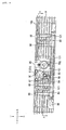
- the internal combustion engine 10 of the present embodiment is an in-line four-cylinder engine as shown in Fig. 1 .
- An outer shell of the engine mainly includes a crankcase 11 composed of an upper crankcase 12 and a lower crankcase 13; a cylinder block 14 mounted to the front upper end of the crankcase 11; a cylinder head 15 mounted to the upper end of the cylinder block 14; a cylinder head cover 16 covering the upper opening of the cylinder head 15; an oil pan 17 covering the lower end opening of the crankcase 11 and storing oil; and a crankcase side cover not shown covering the openings of the left and right lateral surfaces of the crankcase 11.
- the cylinder head 15 is formed at a rear surface with an intake port 18 joined with a throttle body not shown and at a front surface with an exhaust port 19 joined with an exhaust pipe not shown.
- a combustion chamber 20 is formed below the lower surface of the cylinder head 15.
- a spark plug 20a is attached to a plug seat 15a of the cylinder head 15 so as to face the combustion chamber 20.
- the crankcase 11 includes a crank chamber 21 at a front portion and a transmission chamber 22 at a rear portion.
- a crankshaft 23 is rotatably journaled inside the crank chamber 21 via bearings not shown at a mating surface between the upper crankcase 12 and the lower crankcase 13.
- a piston 25 is connected to the crankshaft 23 via a connecting rod 24.
- the piston 25 is reciprocated in a cylinder axial direction in each of cylinder bores 14a of in-line four cylinders included in the cylinder block 14.
- the cylinder axis is arranged to be inclined forwardly of a vehicle traveling direction.
- the transmission chamber 22 is disposed on the rear side of the cylinder block 14.
- a constant-mesh type transmission 26 is housed in the transmission chamber 22.
- This transmission 26 includes a main shaft 27, a countershaft 28, a plurality of drive gears 29, a plurality of driven gears 30, a plurality of shift forks 31 and a shift drum 32.
- the main shaft 27 and countershaft 28 are rotatably journaled via bearings not shown provided at a mating surface between the upper crankcase 12 and the lower crankcase 13.
- the drive gears 29 are provided on the main shaft 27.
- the driven gears 30 are provided on the countershaft 28 so as to mesh with the drive gears 29.
- the shift forks 31 are engaged with the drive gears 29 and with the driven gears 30.
- the shift drum 32 is turnably carried by the crankcase 11 so as to slidably move the shift forks 31 in an axial direction.
- the rotational drive force of the crankshaft 23 is transmitted to the transmission 26 via a primary drive gear 33 provided on the crankshaft 23, a primary driven gear 34 provided on the main shaft 27 so as to mesh with the primary drive gear 33, and a clutch device 35 provided on the main shaft 27.
- a balancer gear 36 meshed with the primary drive gear 33 is housed in the crank chamber 21.
- a cam chain chamber 37 is formed in the cylinder block 14 and cylinder head 15 at a cylinder-arrangement directional central portion so as to house a drive transmission device 38 of a valve train provided in the cylinder head 15.
- This cam chain chamber 37 communicates with the crank chamber 21.
- the drive transmission device 38 includes a cam drive gear 38a provided on the crankshaft 23; cam driven gears 38c, 38c provided on two respective cam shafts 38b, 38b rotatably journaled by the cylinder head 15; and a cam chain 38d wound around the cam drive gear 38a and around the cam driven gears 38c, 38c.
- the drive transmission device 38 further includes a chain tensioner 38e in contact with an upward outer circumferential surface of the cam chain 38d; a chain guide 38f in contact with a downward outer circumferential surface of the cam chain 38d; and a tensioner lifter 38g adapted to press the chain tensioner 38e from the rear side thereof and apply appropriate tensile force to the cam chain 38d.
- the internal combustion engine 10 of the embodiment is provided with a cooling system 40 for cooling the engine 10.
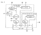
- the cooling system 40 mainly includes an oil pump unit 50, a thermostat 60, an oil jacket (a cooling portion) 70, an oil cooler 41 (see Fig. 8 ), and a cooling system oil passage 80.
- the oil pump unit 50 sucks oil in the oil pan 17 and supplies it under pressure therefrom.
- the thermostat 60 is disposed on the rear surface portion of the cylinder block 14.
- the oil jacket 70 is formed inside the cylinder head 15 to allow circulating oil to cool heat transmitted from the combustion chamber 20.
- the oil cooler 41 is adapted to cool oil.
- the cooling system oil passage 80 interconnects the oil pump unit 50, the thermostat 60, the oil jacket 70, the oil cooler 41 and the crank chamber 21 for communication with one another.
- the oil pump unit 50 is mounted to the right lateral surface of the lower crankcase 13.
- the oil pump unit 50 includes a cooling oil pump 51 and a lubricating oil pump 52 horizontally juxtaposed to each other; a strainer 53 disposed close to the bottom of the oil pan 17; and an oil suction pipe 54 connecting each of the cooling oil pump 51 and the lubricating oil pump 52 with the strainer 53.
- the oil pump unit 50 is driven by the rotational driving force of the crankshaft 23 transmitted via a pump drive gear 55, a pump driven gear 57, and a pump chain 58.
- the pump drive gear 55 is provided on the crankshaft 23.
- the pump driven gear 57 is provided on a pump shaft 56 shared by the cooling oil pump 51 and the lubricating oil pump 52.
- the pump chain 58 is spanned between and wound around the pump drive gear 55 and the pump driven gear 57.
- the thermostat 60 includes a thermostat case 61 disposed on the rear surface portion of the cylinder block 14 and a thermostat valve 63 housed in a thermostat chamber 62 formed in the thermostat case 61.
- the thermostat case 61 has a case main body 64 formed integrally with the cylinder block 14 and a lid portion 65 closing an upper end opening of the case body 64.
- the thermostat 60 switches between opening and closing of an oil discharge side connecting portion 87 which is an oil passage routed through an oil cooler 41 described later and of a bypass passage 84 bypassing the oil cooler 41, in response to the temperature of oil flowing into the thermostat chamber 62.
- the thermostat 60 is disposed rearward of the cylinder block 14 and above the transmission chamber 22.
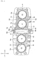
- the oil jacket 70 includes first jacket passages 71, 71, second jacket passages 72, 72, and jacket bypass passages 73, 73.
- the first jacket passages 71, 71 are respectively formed to be routed through the peripheries of plug seats 15a of two inside cylinders IC, IC from the sides of the intake ports 18 of the cylinder head 15 toward the exhaust ports 19.
- the second jacket passages 72, 72 are respectively formed to be routed through the peripheries of plug seats 15a of two outside cylinders OC, OC from the sides of the intake ports 18 of the cylinder head 15 toward the exhaust ports 19. Then, the second jacket passages 72, 72 merge at downstream ends with the corresponding downstream ends of the first jacket passages 71.
- the jacket bypass passages 73, 73 each allow the first jacket passage 71 and the second jacket passage 72 to communicate with each other on the periphery of the plug seat 15a.
- a sand-stripping hole 74 is formed in the lower surface of an almost-central portion of the jacket bypass passage 73 included in the cylinder head 15 so as to draw collapsing sand of a core used to form the oil jacket 70.
- a sand-drawing plug 75 is fitted into the sand-stripping hole 74 so as to project into the jacket bypass passage 73.
- the cooling system oil passage 80 includes a cooling oil supply pipe 81, a first oil supply passage 82, a second oil supply passage 83, a bypass passage 84, an oil distribution passage 85, oil branch passages 86, 86, 86, 86, an oil discharge side connecting portion 87, an oil return side connecting portion 88, and an oil discharge passage (an oil return passage) 89.
- the cooling oil supply pipe 81 is connected to a discharge port 51 a of the cooling oil pump 51.
- the first oil supply passage 82 is formed at the front upper end of the upper crankcase 12 so as to extend upward and connects with the cooling oil supply pipe 81.
- the second oil supply passage 83 is formed in the rear surface portion of the cylinder block 14 so as to extend upward and communicate at its lower end with the first block oil supply passage 82 and at its upper end with the thermostat chamber 62.
- the bypass passage 84 is formed in the rear surface portion of the cylinder block 14 to extend downward and communicate with the thermostat chamber 62 at its upper end.
- the oil distribution passage 85 is formed in the rear surface portion of the cylinder block 14 to extend along the cylinder-arrangement direction and communicate with the lower end of the bypass passage 84.
- the oil branch passages 86, 86, 86, 86 are formed in the rear surface portion of the cylinder block 14 so as to extend upward and communicate with the oil distribution passage 85 at its lower end and with the corresponding respective upstream ends of the first and second jacket passages 71, 71, 72, 72 at its upper end.
- the oil discharge side connecting portion 87 is formed in the lid portion 65 of the thermostat case 61 to communicate with the thermostat chamber 62 and connect with a pipe led to the oil cooler 41.
- the oil return side connecting portion 88 is formed in the rear surface portion of the cylinder block 14 so as to connect with a return pipe led from the oil cooler 41 and communicate with the bypass passage 84.
- the oil discharge passage (the oil return passage) 89 is formed in the cylinder block 14, adapted to draw out oil from the oil jacket 70 and formed with a discharge port 89a opening in the cam chain chamber 37.
- the oil discharge passage 89 communicates with the downstream end of the first jacket passage 71 and functions to return oil from the oil jacket 70 to the oil pan 17 which is the oil supply side.
- the oil discharge passage 89 is formed in the upper surface of the cylinder block 14 and close to the inside cylinder IC and to the exhaust port 19 so as to extend toward the cam chain chamber 37 like a groove. In this way, the exhaust ports 19, 19 of the inside cylinders IC, IC can efficiently be cooled.
- the discharge ports 89a of the oil discharge passages 89 are each provided to face the downward (the front of Fig. 2 ) lateral surface of the cam chain 38d of the drive transmission device 38.
- the oil discharged from the discharge port 89a is transferred to the downside of the internal combustion engine 10 by the cam chain 38d and returned into the oil pan 17.
- the chain guide 38f is provided to extend downward from the discharge port 89a.
- the oil discharged from the discharge port 89a hits the cam chain 38d, and then is led downward of the internal combustion engine 10 by the chain guide 38f and returned into the oil pan 17.
- the oil discharge passage 89 is formed like a groove in the mating surface 14b between the cylinder block 14 and the cylinder head 15 to extend from the downstream end of the first jacket passage 71 toward the cam chain chamber 37.
- the oil discharge passage 89 communicates with the downstream end of the first jacket passages 71 at its upstream end. Thus, oil is transferred from the downstream end of the first jacket passage 71 to the upstream end of the oil discharge passage 89.
- the cylinder axis of the cylinder bore 14a is forwardly inclined along the downward side of the cam chain 38d.
- the oil discharge passage 89 is formed to communicate with the discharge port 89a from the inclined-directional upside toward the inclined-directional downside.
- a cooling system oil passage 90 adapted to supply oil to lubrication portions (various rotating shafts, gears, etc.) of the internal combustion engine 10 is connected to the discharge port 52a of the lubricating oil pump 52.
- the lubricating system oil passage 90 includes a lubricating oil supply pipe 91 connected to the discharge port 52a of the lubricating oil pump 52; and a lubricating oil passage 92 adapted to supply oil to the lubrication portions of the internal combustion engine 10.
- the cooling system oil passage 80 and the lubricating system oil passage 90 are provided independently of each other so as to extend from the oil pan 17 as a source.
- the thermostat valve 63 of the thermostat 60 is disposed in the thermostat chamber 62 which is an oil passage between the cooling oil pump 51 and the oil jacket 70.
- the oil return side connecting portion 88 which is a return oil passage of the oil cooler 41 is connected to the bypass passage 84 which is an oil passage between the thermostat chamber 62 of the thermostat 60 and the oil jacket 70.
- a bulging portion 95 resulting from the cam chain chamber 37 is formed at the cylinder-arrangement directional central portion of the rear surface of the cylinder block 14 and cylinder head 15.
- the thermostat 60 is provided adjacently to the left of the bulging portion 95.
- the tensioner lifter 38g for applying adequate tensile force to the cam chain 38d is attached to the bulging portion 95 of the cylinder block 14 at the horizontally central position thereof.
- the thermostat 60 is disposed at a position overlapping the tensioner lifter 38g as viewed from the side.
- the following are formed to be exposed to the mating surface 15b of the cylinder head 15 with the cylinder block 14: the upstream end of the first jacket passage 71 which is an end of the first jacket passage 71 close to the intake port 18; the downstream end of the first jacket passage 71 which is an end of the first jacket passage 71 close to the exhaust port 19; the upstream end of the second jacket passage 72 which an end of the second jacket passage 72 close to the intake port 18; and an through-hole 76 adapted to receive a leg portion, passed therethrough, of the core used to form the oil jacket 70, the through-hole 76 being an end of the second jacket passage 72 close to the exhaust port 19.
- the through-hole 76 is closed with a plug member 77.
- an oil temperature sensor 96 is disposed at the rearward of the cylinder block 14 in the vehicle traveling direction.
- This oil temperature sensor 96 is attached from the axial direction of the oil distribution passage 85 to a screw portion not shown formed on the internal circumference of the left end of the oil distribution passage 85.
- the oil temperature sensor 96 is disposed inwardly of the cylinder-arrangement directional end of the cylinder block 14.
- the oil branch passages 86 are formed in the rear surface portion of the cylinder block 14 so as to be separate from the corresponding cylinder bores 14a. Therefore, the oil passing through the oil branch passages 86 can be prevented from being heated by the cylinder bores 14a and the like. This makes it possible to improve the cooling efficiency of the oil jacket 70.
- a cooling air passage 101 is formed between the adjacent cylinder bores 14a of the respective cylinders of the cylinder block 14 so as to lead cooling air (running air) from the front to rear of the vehicle.
- the oil branch passages 86 are formed in the rear surface portion of the cylinder block 14 independently of each other for each cylinder.
- the oil branch passages 86 are arranged in the vicinity of the cooling air passages 101, specifically, adjacently to rear left and right portions of the respective external cooling air passages 101.
- the cooling air that has passed through the cooling air passages 101 smoothly flows along the inside surfaces between the adjacent oil branch passages 86, 86 and is discharged rearward.
- a first cooling air introduction passage 104 is formed to longitudinally pass through a portion close to the exhaust port 19 and between the inside cylinder IC and the cam chain chamber 37 of the cylinder block 14 and of the cylinder head 15.
- This first cooling air introduction passage 104 communicates from the internal cooling air passage 101 to a recessed portion 39 (see Fig. 1 ) formed above the cylinder head 15.
- Second cooling air introduction passages 105, 105 are formed to longitudinally pass through respective portions forward of and rearward of a line connecting the respective cylinder centers of the inside cylinder IC and outside cylinder OC included in the cylinder block 14 and in the cylinder head 15.
- the second cooling air introduction passages 105, 105 communicate from the front and rear ends of the external cooling air passage 101 to the recessed portion 39.
- a portion of cooling air led to the internal cooling air passage 101 is led to the first cooling air introduction passage 104 to cool between the cam chain chamber 37 and the inside cylinder IC and is then led into the recessed portion 39.
- a portion of cooling air led to the external cooling air passage 101 and a portion of cooling air having passed through the external cooling air passage 101 are led into the second cooling air introduction passages 105, 105 to cool between the inside cylinder IC and outside cylinder OC and is then led into the recessed portion 39.
- the cooling air led into the recessed portion 39 cools the portions inside the recessed portion 39 and the peripheries of the plug seat 15a and then is led to the outside from the opening portion at the cylinder-arrangement directional outer ends of the recessed portion 39.
- the oil supplied under pressure from the cooling oil pump 51 because of the bypass passage 84 opened by the thermostat valve 63, circulates in the following order: the cooling oil supply pipe 81 ⁇ the first oil supply passage 82 ⁇ the second oil supply passage 83 ⁇ the thermostat chamber 62 ⁇ the bypass passage 84 ⁇ the oil distribution passage 85 ⁇ the oil branch passage 86 ⁇ the oil jacket 70 ⁇ the oil discharge passage 89 ⁇ the cam chain chamber 37 ⁇ the crank chamber 21 ⁇ the oil pan 17 ⁇ the cooling oil pump 51.
- the oil supplied under pressure from the cooling oil pump 51 because of the oil discharge side connecting portion 87 opened by the thermostat valve 63, circulates in the following order: the cooling oil supply pipe 81 ⁇ the first oil supply passage 82 ⁇ the second oil supply passage 83 ⁇ the thermostat chamber 62 ⁇ the oil discharge side connecting portion 87 ⁇ the oil cooler 41 ⁇ the oil return side connecting portion 88 ⁇ the bypass passage 84 ⁇ the oil distribution passage 85 ⁇ the oil branch passage 86 ⁇ the oil jacket 70 ⁇ the oil discharge passage 89 ⁇ the cam chain chamber 37 ⁇ the crank chamber 21 ⁇ the oil pan 21 ⁇ the cooling oil pump 51.
- the thermostat 60 is disposed in the oil passage between the cooling oil pump 51 and the oil jacket 70 and upstream of the oil jacket 70. Therefore, the temperature of the oil supplied to the oil jacket 70 can appropriately be controlled to thereby improve the cooling efficiency of the oil jacket 70.
- the oil return side connecting portion 88 or return oil passage of the oil cooler 41 is connected to the oil passage between the thermostat 60 and the oil jacket 70. Therefore, oil cooled by the oil cooler 41 can directly be supplied to the oil jacket 70. This can prevent oil from being heated by other portions of the internal combustion engine 10 to further improve the cooling efficiency of the oil jacket 70.
- the cooling system 40 of the internal combustion engine 10 of the present embodiment includes the lubricating system oil passage 90 adapted to supply oil to the lubrication portions of the engine 10, the cooling system oil passage 80 adapted to supply oil to the oil jacket 70, and the oil pan 17 for storing oil.
- the lubricating system oil passage 90 and the cooling system oil passage 80 are provided independently of each other with the oil pan 17 serving as a source.
- the oil cooler 41 is disposed in the cooling system oil passage 80 where oil largely rises in temperature. Thus, the cooling efficiency of the oil jacket 70 can further be improved.
- the internal combustion engine 10 is an internal combustion engine for small-sized vehicles and includes the transmission 20 on the rear side of the cylinder block 14 with respect to the vehicle traveling direction, and the thermostat 60 is disposed rearward of the cylinder block 14 and above the transmission chamber 20. Therefore, the exposure of the thermostat 60 can be suppressed if the internal combustion engine 10 is viewed from the front of the vehicle, thereby improving external appearance. It is not necessary to additionally prepare a member for protecting the thermostat 60 as compared with the case where the thermostat is disposed forward of the internal combustion engine 10. Therefore, the number of component parts can be reduced to thereby reduce the weight of the internal combustion engine 10.
- the bulging portion 95 disposed at the cylinder-arrangement directional central portion is formed as the cam chain chamber 37 in the cylinder block 14 and in the cylinder head 15.
- the thermostat 60 is provided adjacently to the bulging portion 95. Therefore, the bulging portions of the internal combustion engine 10 can be collected to thereby improve the flexibility of arrangement of other auxiliary machinery or peripheral structures of the internal combustion engine 10.
- the present invention is directed to provide a cooling system of an internal combustion engine that can improve the cooling efficiency of a cooling portion.
- a cooling system includes: an oil pump 51 for supplying oil under pressure; a cylinder head 15 forming part of a combustion chamber 20; a cooling portion 70 formed in the cylinder head 15 and adapted to allow circulating oil to cool heat transmitted from the combustion chamber 20; an oil cooler 41 for cooling oil; and a thermostat 60 for switching between an oil passage 87 routed through the oil cooler 41 and a bypass passage 84 bypassing the oil cooler 41.
- the thermostat 60 is disposed in an oil passage between the oil pump 51 and the cooling portion 70.
Landscapes
- Engineering & Computer Science (AREA)
- Chemical & Material Sciences (AREA)
- Combustion & Propulsion (AREA)
- Mechanical Engineering (AREA)
- General Engineering & Computer Science (AREA)
- Lubrication Of Internal Combustion Engines (AREA)
Abstract
Description
- The present invention relates generally to a cooling system of an internal combustion engine, and particularly, to a cooling system of an internal combustion engine for a motorcycle.
- There is known a traditional cooling system of an internal combustion engine, which includes a generally forwardly inclined cylinder provided in the engine; an oil jacket formed in a cylinder head joined to the cylinder and adapted to cool the cylinder head; an oil cooler disposed forward of the engine; and a thermostat that exercises such control as to introduce or divert oil to or from the oil cooler. In addition, the thermostat is directly attached to the front of the crankcase. Oil having passed through the oil jacket is discharged to the front of the cylinder head, i.e., of the engine. The oil discharged forward of the engine is passed through the thermostat and then delivered to the oil cooler or to a bypass passage bypassing the oil cooler depending on temperature conditions (See e.g. Japanese Patent Document No.
JP 2006-976121 A - However, in the cooling system of the internal combustion engine described in Japanese Patent Document No.
JP 2006-976121 A - The present invention has been made to eliminate such a disadvantage and aims to provide a cooling system of an internal combustion engine that can improve the cooling efficiency of a cooling portion.
- To achieve the above object, the invention recited in claim 1 is characterized in that in a cooling system of an internal combustion engine, including: an oil pump for supplying oil under pressure; a cylinder head forming part of a combustion chamber; a cooling portion formed in the cylinder head and adapted to allow circulating oil to cool heat transmitted from the combustion chamber; an oil cooler for cooling oil; and a thermostat for switching between an oil passage routed through the oil cooler and a bypass passage bypassing the oil cooler; the thermostat is disposed in an oil passage between the oil pump and the cooling portion.
- The invention recited in claim 2 is characterized in that, in addition to the configuration of the invention recited in claim 1, a return oil passage of the oil cooler is connected to an oil passage between the thermostat and the cooling portion.
- The invention recited in claim 3 is characterized, in addition to the configuration of the invention recited in claim 2, by further including a lubricating system oil passage adapted to supply oil to a lubrication portion of the internal combustion engine; a cooling system oil passage adapted to supply oil to the cooling portion; and an oil pan for storing oil; and in that the lubricating system oil passage and the cooling system oil passage are provided independently of each other so as to use the oil pan as a source.
- The invention recited in claim 4 is characterized in that, in addition to the configuration of the invention recited in claim 1, 2 or 3, the internal combustion engine is an internal combustion engine for a small-sized vehicle, and includes a transmission chamber provided on the rear side of a cylinder block with respect to a traveling direction of the vehicle, and the thermostat is disposed rearward of the cylinder block and above the transmission chamber.
- The invention recited in claim 5 is characterized in that, in addition to the configuration of the invention recited in claim 4, the cylinder block and the cylinder head are formed with a bulging portion as part of a cam chain chamber at a cylinder-arrangement directional central portion, and the thermostat is provided adjacently to the bulging portion.
- According to the cooling system of an internal combustion engine recited in claim 1, since the thermostat is disposed in the oil passage between the oil pump and the cooling portion and provided upstream of the cooling portion, the temperature of oil supplied to the cooling portion can accurately controlled to thereby improve the cooling efficiency of the cooling portion.
- According to the cooling system of an internal combustion engine recited in claim 2, since the return oil passage of the oil cooler is connected to the oil passage between the thermostat and the cooling portion, oil cooled by the oil cooler can directly be supplied to the cooling portion. Thus, oil can be prevented from being heated by other portions of the internal combustion engine to thereby further improving the cooling efficiency of the cooling portion.
- According to the cooling system of an internal combustion engine recited in claim 3, the cooling system further includes the lubricating system oil passage adapted to supply oil to a lubrication portion of the internal combustion engine; the cooling system oil passage adapted to supply oil to the cooling portion; and the oil pan for storing oil; and the lubricating system oil passage and the cooling system oil passage are provided independently of each other with the oil pan used as a source. Therefore, the oil cooler is disposed in the cooling system oil passage where oil largely rises in temperature. Thus, the cooling efficiency of the cooling portion can further be improved.
- According to the cooling system of an internal combustion engine recited in claim 4, the internal combustion engine is an internal combustion engine for a small-sized vehicle, and includes the transmission chamber provided on the rear side of the cylinder block with respect to a traveling direction of the vehicle, and the thermostat is disposed rearward of the cylinder block and above the transmission chamber. Therefore, exposure of the thermostat can be prevented when the internal combustion engine is viewed from the front of the vehicle, thereby improving external appearance. In addition, since it is not necessary to additionally prepare a member for protecting the thermostat, the number of component parts can be reduced to reduce the weight of the internal combustion engine as compared with the case where the thermostat is disposed forward of the internal combustion engine.
- According to the cooling system of an internal combustion engine recited in claim 5, the cylinder block and the cylinder head are formed with the bulging portion as part of the cam chain chamber at a cylinder-arrangement directional central portion, and the thermostat is provided adjacently to the bulging portion. Therefore, the bulging portions of the internal combustion engine can be collected to thereby improve the flexibility of arrangement of other auxiliary machinery or peripheral structures of the engine.
-
-
Fig. 1 is a partial cutout right lateral view for assistance in explaining an embodiment of a cooling system of an internal combustion engine according to the present invention. -
Fig. 2 is a partial cutout right lateral view for assistance in explaining a drive transmission device of a valve train of the internal combustion engine according to the invention. -
Fig. 3 is an enlarged right lateral view illustrating the periphery of a thermostat shown inFig. 1 . -
Fig. 4 is a rear view of a cylinder block shown inFig. 1 . -
Fig. 5 is a plan view of the cylinder block shown inFig. 4 . -
Fig. 6 is a cross-sectional view taken along line A-A ofFig. 4 . -
Fig. 7 is a bottom view of a cylinder head shown inFig. 1 . -
Fig. 8 is a schematic diagram for assistance in explaining an oil circulation circuit of the cooling system of the internal combustion engine according to the present invention. - An embodiment of a cooling system of an internal combustion engine according to the present invention will hereinafter be described in detail with reference to the accompanying drawings. Incidentally, the internal combustion engine of the present embodiment is mounted on a motorcycle not shown. In the following description, the front and back or rear, the left and right, and upside and downside are based on the direction a rider faces. In the drawings, the front, back or rear, left, right, upside and downside of a motorcycle are denoted with Fr, Rr, L, R, U and D, respectively.
- The
internal combustion engine 10 of the present embodiment is an in-line four-cylinder engine as shown inFig. 1 . An outer shell of the engine mainly includes acrankcase 11 composed of anupper crankcase 12 and alower crankcase 13; acylinder block 14 mounted to the front upper end of thecrankcase 11; acylinder head 15 mounted to the upper end of thecylinder block 14; acylinder head cover 16 covering the upper opening of thecylinder head 15; anoil pan 17 covering the lower end opening of thecrankcase 11 and storing oil; and a crankcase side cover not shown covering the openings of the left and right lateral surfaces of thecrankcase 11. - The
cylinder head 15 is formed at a rear surface with anintake port 18 joined with a throttle body not shown and at a front surface with anexhaust port 19 joined with an exhaust pipe not shown. Acombustion chamber 20 is formed below the lower surface of thecylinder head 15. Aspark plug 20a is attached to aplug seat 15a of thecylinder head 15 so as to face thecombustion chamber 20. - As shown in
Fig. 1 , thecrankcase 11 includes acrank chamber 21 at a front portion and atransmission chamber 22 at a rear portion. Acrankshaft 23 is rotatably journaled inside thecrank chamber 21 via bearings not shown at a mating surface between theupper crankcase 12 and thelower crankcase 13. Apiston 25 is connected to thecrankshaft 23 via a connectingrod 24. Thepiston 25 is reciprocated in a cylinder axial direction in each ofcylinder bores 14a of in-line four cylinders included in thecylinder block 14. In the embodiment, the cylinder axis is arranged to be inclined forwardly of a vehicle traveling direction. - The
transmission chamber 22 is disposed on the rear side of thecylinder block 14. A constant-mesh type transmission 26 is housed in thetransmission chamber 22. Thistransmission 26 includes amain shaft 27, acountershaft 28, a plurality ofdrive gears 29, a plurality of drivengears 30, a plurality ofshift forks 31 and ashift drum 32. Themain shaft 27 andcountershaft 28 are rotatably journaled via bearings not shown provided at a mating surface between theupper crankcase 12 and thelower crankcase 13. Thedrive gears 29 are provided on themain shaft 27. The drivengears 30 are provided on thecountershaft 28 so as to mesh with thedrive gears 29. Theshift forks 31 are engaged with thedrive gears 29 and with the drivengears 30. Theshift drum 32 is turnably carried by thecrankcase 11 so as to slidably move theshift forks 31 in an axial direction. - The rotational drive force of the
crankshaft 23 is transmitted to thetransmission 26 via aprimary drive gear 33 provided on thecrankshaft 23, a primary drivengear 34 provided on themain shaft 27 so as to mesh with theprimary drive gear 33, and aclutch device 35 provided on themain shaft 27. Abalancer gear 36 meshed with theprimary drive gear 33 is housed in thecrank chamber 21. - As shown in
Figs. 2 and5 through 7 , acam chain chamber 37 is formed in thecylinder block 14 andcylinder head 15 at a cylinder-arrangement directional central portion so as to house adrive transmission device 38 of a valve train provided in thecylinder head 15. Thiscam chain chamber 37 communicates with thecrank chamber 21. - As shown in
Fig. 2 , thedrive transmission device 38 includes acam drive gear 38a provided on thecrankshaft 23; cam drivengears respective cam shafts cylinder head 15; and acam chain 38d wound around thecam drive gear 38a and around the cam drivengears drive transmission device 38 further includes achain tensioner 38e in contact with an upward outer circumferential surface of thecam chain 38d; achain guide 38f in contact with a downward outer circumferential surface of thecam chain 38d; and atensioner lifter 38g adapted to press thechain tensioner 38e from the rear side thereof and apply appropriate tensile force to thecam chain 38d. - The
internal combustion engine 10 of the embodiment is provided with acooling system 40 for cooling theengine 10. As shown inFigs. 1 through 8 , thecooling system 40 mainly includes anoil pump unit 50, athermostat 60, an oil jacket (a cooling portion) 70, an oil cooler 41 (seeFig. 8 ), and a coolingsystem oil passage 80. Theoil pump unit 50 sucks oil in theoil pan 17 and supplies it under pressure therefrom. Thethermostat 60 is disposed on the rear surface portion of thecylinder block 14. Theoil jacket 70 is formed inside thecylinder head 15 to allow circulating oil to cool heat transmitted from thecombustion chamber 20. Theoil cooler 41 is adapted to cool oil. The coolingsystem oil passage 80 interconnects theoil pump unit 50, thethermostat 60, theoil jacket 70, theoil cooler 41 and thecrank chamber 21 for communication with one another. - As shown in
Fig. 1 , theoil pump unit 50 is mounted to the right lateral surface of thelower crankcase 13. In addition, theoil pump unit 50 includes a coolingoil pump 51 and alubricating oil pump 52 horizontally juxtaposed to each other; astrainer 53 disposed close to the bottom of theoil pan 17; and anoil suction pipe 54 connecting each of the coolingoil pump 51 and the lubricatingoil pump 52 with thestrainer 53. - The
oil pump unit 50 is driven by the rotational driving force of thecrankshaft 23 transmitted via apump drive gear 55, a pump drivengear 57, and apump chain 58. Thepump drive gear 55 is provided on thecrankshaft 23. The pump drivengear 57 is provided on apump shaft 56 shared by the coolingoil pump 51 and the lubricatingoil pump 52. Thepump chain 58 is spanned between and wound around thepump drive gear 55 and the pump drivengear 57. - The
thermostat 60 includes athermostat case 61 disposed on the rear surface portion of thecylinder block 14 and athermostat valve 63 housed in athermostat chamber 62 formed in thethermostat case 61. Thethermostat case 61 has a casemain body 64 formed integrally with thecylinder block 14 and alid portion 65 closing an upper end opening of thecase body 64. Thethermostat 60 switches between opening and closing of an oil dischargeside connecting portion 87 which is an oil passage routed through an oil cooler 41 described later and of abypass passage 84 bypassing theoil cooler 41, in response to the temperature of oil flowing into thethermostat chamber 62. In the present embodiment, thethermostat 60 is disposed rearward of thecylinder block 14 and above thetransmission chamber 22. - Referring to
Fig. 7 , theoil jacket 70 includesfirst jacket passages second jacket passages jacket bypass passages first jacket passages plug seats 15a of two inside cylinders IC, IC from the sides of theintake ports 18 of thecylinder head 15 toward theexhaust ports 19. Thesecond jacket passages plug seats 15a of two outside cylinders OC, OC from the sides of theintake ports 18 of thecylinder head 15 toward theexhaust ports 19. Then, thesecond jacket passages first jacket passages 71. Thejacket bypass passages first jacket passage 71 and thesecond jacket passage 72 to communicate with each other on the periphery of theplug seat 15a. - A sand-stripping
hole 74 is formed in the lower surface of an almost-central portion of thejacket bypass passage 73 included in thecylinder head 15 so as to draw collapsing sand of a core used to form theoil jacket 70. A sand-drawingplug 75 is fitted into the sand-strippinghole 74 so as to project into thejacket bypass passage 73. - As shown in
Figs. 1 through 8 , the coolingsystem oil passage 80 includes a coolingoil supply pipe 81, a firstoil supply passage 82, a secondoil supply passage 83, abypass passage 84, anoil distribution passage 85,oil branch passages side connecting portion 87, an oil returnside connecting portion 88, and an oil discharge passage (an oil return passage) 89. The coolingoil supply pipe 81 is connected to adischarge port 51 a of the coolingoil pump 51. The firstoil supply passage 82 is formed at the front upper end of theupper crankcase 12 so as to extend upward and connects with the coolingoil supply pipe 81. The secondoil supply passage 83 is formed in the rear surface portion of thecylinder block 14 so as to extend upward and communicate at its lower end with the first blockoil supply passage 82 and at its upper end with thethermostat chamber 62. Thebypass passage 84 is formed in the rear surface portion of thecylinder block 14 to extend downward and communicate with thethermostat chamber 62 at its upper end. Theoil distribution passage 85 is formed in the rear surface portion of thecylinder block 14 to extend along the cylinder-arrangement direction and communicate with the lower end of thebypass passage 84. Theoil branch passages cylinder block 14 so as to extend upward and communicate with theoil distribution passage 85 at its lower end and with the corresponding respective upstream ends of the first andsecond jacket passages side connecting portion 87 is formed in thelid portion 65 of thethermostat case 61 to communicate with thethermostat chamber 62 and connect with a pipe led to theoil cooler 41. The oil returnside connecting portion 88 is formed in the rear surface portion of thecylinder block 14 so as to connect with a return pipe led from theoil cooler 41 and communicate with thebypass passage 84. The oil discharge passage (the oil return passage) 89 is formed in thecylinder block 14, adapted to draw out oil from theoil jacket 70 and formed with adischarge port 89a opening in thecam chain chamber 37. - In the embodiment, as shown in
Fig. 5 , theoil discharge passage 89 communicates with the downstream end of thefirst jacket passage 71 and functions to return oil from theoil jacket 70 to theoil pan 17 which is the oil supply side. In addition, theoil discharge passage 89 is formed in the upper surface of thecylinder block 14 and close to the inside cylinder IC and to theexhaust port 19 so as to extend toward thecam chain chamber 37 like a groove. In this way, theexhaust ports - In the embodiment, as shown in
Figs. 2 and5 , thedischarge ports 89a of theoil discharge passages 89 are each provided to face the downward (the front ofFig. 2 ) lateral surface of thecam chain 38d of thedrive transmission device 38. Thus, the oil discharged from thedischarge port 89a is transferred to the downside of theinternal combustion engine 10 by thecam chain 38d and returned into theoil pan 17. - In the embodiment, as shown in
Fig. 2 , thechain guide 38f is provided to extend downward from thedischarge port 89a. Thus, the oil discharged from thedischarge port 89a hits thecam chain 38d, and then is led downward of theinternal combustion engine 10 by thechain guide 38f and returned into theoil pan 17. - In the embodiment, as shown in
Fig. 5 , theoil discharge passage 89 is formed like a groove in themating surface 14b between thecylinder block 14 and thecylinder head 15 to extend from the downstream end of thefirst jacket passage 71 toward thecam chain chamber 37. Theoil discharge passage 89 communicates with the downstream end of thefirst jacket passages 71 at its upstream end. Thus, oil is transferred from the downstream end of thefirst jacket passage 71 to the upstream end of theoil discharge passage 89. - In the embodiment, as shown in
Figs. 2 and5 , the cylinder axis of thecylinder bore 14a is forwardly inclined along the downward side of thecam chain 38d. Theoil discharge passage 89 is formed to communicate with thedischarge port 89a from the inclined-directional upside toward the inclined-directional downside. - As shown in
Fig. 1 , a coolingsystem oil passage 90 adapted to supply oil to lubrication portions (various rotating shafts, gears, etc.) of theinternal combustion engine 10 is connected to thedischarge port 52a of the lubricatingoil pump 52. The lubricatingsystem oil passage 90 includes a lubricatingoil supply pipe 91 connected to thedischarge port 52a of the lubricatingoil pump 52; and alubricating oil passage 92 adapted to supply oil to the lubrication portions of theinternal combustion engine 10. In this way, the coolingsystem oil passage 80 and the lubricatingsystem oil passage 90 are provided independently of each other so as to extend from theoil pan 17 as a source. - In the embodiment, as shown in
Fig. 3 , thethermostat valve 63 of thethermostat 60 is disposed in thethermostat chamber 62 which is an oil passage between the coolingoil pump 51 and theoil jacket 70. - In the embodiment, as shown in
Fig. 3 , the oil returnside connecting portion 88 which is a return oil passage of theoil cooler 41 is connected to thebypass passage 84 which is an oil passage between thethermostat chamber 62 of thethermostat 60 and theoil jacket 70. - In the embodiment, as shown in
Figs. 4 through 7 , a bulgingportion 95 resulting from thecam chain chamber 37 is formed at the cylinder-arrangement directional central portion of the rear surface of thecylinder block 14 andcylinder head 15. Thethermostat 60 is provided adjacently to the left of the bulgingportion 95. - In the embodiment, as shown in
Figs. 2 and3 , thetensioner lifter 38g for applying adequate tensile force to thecam chain 38d is attached to the bulgingportion 95 of thecylinder block 14 at the horizontally central position thereof. Thethermostat 60 is disposed at a position overlapping thetensioner lifter 38g as viewed from the side. - In the embodiment, as shown in
Fig. 7 , the following are formed to be exposed to themating surface 15b of thecylinder head 15 with the cylinder block 14: the upstream end of thefirst jacket passage 71 which is an end of thefirst jacket passage 71 close to theintake port 18; the downstream end of thefirst jacket passage 71 which is an end of thefirst jacket passage 71 close to theexhaust port 19; the upstream end of thesecond jacket passage 72 which an end of thesecond jacket passage 72 close to theintake port 18; and an through-hole 76 adapted to receive a leg portion, passed therethrough, of the core used to form theoil jacket 70, the through-hole 76 being an end of thesecond jacket passage 72 close to theexhaust port 19. The through-hole 76 is closed with aplug member 77. - In the embodiment, as shown in
Fig. 4 , anoil temperature sensor 96 is disposed at the rearward of thecylinder block 14 in the vehicle traveling direction. Thisoil temperature sensor 96 is attached from the axial direction of theoil distribution passage 85 to a screw portion not shown formed on the internal circumference of the left end of theoil distribution passage 85. In addition, theoil temperature sensor 96 is disposed inwardly of the cylinder-arrangement directional end of thecylinder block 14. - In the embodiment, the
oil branch passages 86 are formed in the rear surface portion of thecylinder block 14 so as to be separate from the corresponding cylinder bores 14a. Therefore, the oil passing through theoil branch passages 86 can be prevented from being heated by the cylinder bores 14a and the like. This makes it possible to improve the cooling efficiency of theoil jacket 70. - In the embodiment, as shown in
Figs. 4 and6 , a coolingair passage 101 is formed between the adjacent cylinder bores 14a of the respective cylinders of thecylinder block 14 so as to lead cooling air (running air) from the front to rear of the vehicle. Theoil branch passages 86 are formed in the rear surface portion of thecylinder block 14 independently of each other for each cylinder. In addition, theoil branch passages 86 are arranged in the vicinity of the coolingair passages 101, specifically, adjacently to rear left and right portions of the respective externalcooling air passages 101. The cooling air that has passed through the coolingair passages 101 smoothly flows along the inside surfaces between the adjacentoil branch passages - In the embodiment, as shown in
Figs. 1 and5 to 7 , a first coolingair introduction passage 104 is formed to longitudinally pass through a portion close to theexhaust port 19 and between the inside cylinder IC and thecam chain chamber 37 of thecylinder block 14 and of thecylinder head 15. This first coolingair introduction passage 104 communicates from the internalcooling air passage 101 to a recessed portion 39 (seeFig. 1 ) formed above thecylinder head 15. Second coolingair introduction passages cylinder block 14 and in thecylinder head 15. The second coolingair introduction passages cooling air passage 101 to the recessedportion 39. - In this way, a portion of cooling air led to the internal
cooling air passage 101 is led to the first coolingair introduction passage 104 to cool between thecam chain chamber 37 and the inside cylinder IC and is then led into the recessedportion 39. A portion of cooling air led to the externalcooling air passage 101 and a portion of cooling air having passed through the externalcooling air passage 101 are led into the second coolingair introduction passages portion 39. The cooling air led into the recessedportion 39 cools the portions inside the recessedportion 39 and the peripheries of theplug seat 15a and then is led to the outside from the opening portion at the cylinder-arrangement directional outer ends of the recessedportion 39. - In the
cooling system 40 of theinternal combustion engine 10 configured described above, during warm-up operation, the oil supplied under pressure from the coolingoil pump 51, because of thebypass passage 84 opened by thethermostat valve 63, circulates in the following order: the coolingoil supply pipe 81 → the firstoil supply passage 82 → the secondoil supply passage 83 → thethermostat chamber 62 → thebypass passage 84 → theoil distribution passage 85 → theoil branch passage 86 → theoil jacket 70 → theoil discharge passage 89 → thecam chain chamber 37 → thecrank chamber 21 → theoil pan 17 → the coolingoil pump 51. - After the warm-up operation is completed, the oil supplied under pressure from the cooling
oil pump 51, because of the oil dischargeside connecting portion 87 opened by thethermostat valve 63, circulates in the following order: the coolingoil supply pipe 81 → the firstoil supply passage 82 → the secondoil supply passage 83 → thethermostat chamber 62 → the oil dischargeside connecting portion 87 → theoil cooler 41 → the oil returnside connecting portion 88 → thebypass passage 84 → theoil distribution passage 85 → theoil branch passage 86 → theoil jacket 70 → theoil discharge passage 89 → thecam chain chamber 37 → thecrank chamber 21 → theoil pan 21 → the coolingoil pump 51. - As described above, according to the
cooling system 40 of theinternal combustion engine 10 of the present embodiment, thethermostat 60 is disposed in the oil passage between the coolingoil pump 51 and theoil jacket 70 and upstream of theoil jacket 70. Therefore, the temperature of the oil supplied to theoil jacket 70 can appropriately be controlled to thereby improve the cooling efficiency of theoil jacket 70. - According to the
cooling system 40 of theinternal combustion engine 10 of the present embodiment, the oil returnside connecting portion 88 or return oil passage of theoil cooler 41 is connected to the oil passage between thethermostat 60 and theoil jacket 70. Therefore, oil cooled by theoil cooler 41 can directly be supplied to theoil jacket 70. This can prevent oil from being heated by other portions of theinternal combustion engine 10 to further improve the cooling efficiency of theoil jacket 70. - The
cooling system 40 of theinternal combustion engine 10 of the present embodiment includes the lubricatingsystem oil passage 90 adapted to supply oil to the lubrication portions of theengine 10, the coolingsystem oil passage 80 adapted to supply oil to theoil jacket 70, and theoil pan 17 for storing oil. In addition, the lubricatingsystem oil passage 90 and the coolingsystem oil passage 80 are provided independently of each other with theoil pan 17 serving as a source. Further, theoil cooler 41 is disposed in the coolingsystem oil passage 80 where oil largely rises in temperature. Thus, the cooling efficiency of theoil jacket 70 can further be improved. - According to the
cooling system 40 of theinternal combustion engine 10 of the present embodiment, theinternal combustion engine 10 is an internal combustion engine for small-sized vehicles and includes thetransmission 20 on the rear side of thecylinder block 14 with respect to the vehicle traveling direction, and thethermostat 60 is disposed rearward of thecylinder block 14 and above thetransmission chamber 20. Therefore, the exposure of thethermostat 60 can be suppressed if theinternal combustion engine 10 is viewed from the front of the vehicle, thereby improving external appearance. It is not necessary to additionally prepare a member for protecting thethermostat 60 as compared with the case where the thermostat is disposed forward of theinternal combustion engine 10. Therefore, the number of component parts can be reduced to thereby reduce the weight of theinternal combustion engine 10. - According to the
cooling system 40 of theinternal combustion engine 10 of the present embodiment, the bulgingportion 95 disposed at the cylinder-arrangement directional central portion is formed as thecam chain chamber 37 in thecylinder block 14 and in thecylinder head 15. In addition, thethermostat 60 is provided adjacently to the bulgingportion 95. Therefore, the bulging portions of theinternal combustion engine 10 can be collected to thereby improve the flexibility of arrangement of other auxiliary machinery or peripheral structures of theinternal combustion engine 10. - The present invention is directed to provide a cooling system of an internal combustion engine that can improve the cooling efficiency of a cooling portion.
- A cooling system includes: an
oil pump 51 for supplying oil under pressure; acylinder head 15 forming part of acombustion chamber 20; a coolingportion 70 formed in thecylinder head 15 and adapted to allow circulating oil to cool heat transmitted from thecombustion chamber 20; an oil cooler 41 for cooling oil; and athermostat 60 for switching between anoil passage 87 routed through theoil cooler 41 and abypass passage 84 bypassing theoil cooler 41. Thethermostat 60 is disposed in an oil passage between theoil pump 51 and the coolingportion 70.
Claims (5)
- A cooling system (40) of an internal combustion engine (10), comprising:an oil pump for supplying oil under pressure;a cylinder head (15) forming part of a combustion chamber (20);a cooling portion (70) formed in the cylinder head (15) and adapted to allow circulating oil to cool heat transmitted from the combustion chamber (20);an oil cooler (41) for cooling oil; anda thermostat (60) for switching between an oil passage routed through the oil cooler (41) and a bypass passage (84) bypassing the oil cooler (41);wherein the thermostat (60) is disposed in an oil passage between the oil pump and the cooling portion (70).
- The cooling system (40) of an internal combustion engine (10) according to claim 1, wherein a return oil passage (88) of the oil cooler (41) is connected to an oil passage between the thermostat (60) and the cooling portion (70).
- The cooling system (40) of an internal combustion engine (10) according to claim 2, further comprising:a lubricating system oil passage (90) adapted to supply oil to a lubrication portion of the internal combustion engine (10);a cooling system oil passage (80) adapted to supply oil to the cooling portion (70); andan oil pan (17) for storing oil;wherein the lubricating system oil passage (90) and the cooling system oil passage (80) are provided independently of each other so as to use the oil pan (17) as a source.
- The cooling system (40) of an internal combustion engine (10) according to claim 1, 2 or 3, wherein
the internal combustion engine (10) is an internal combustion engine for a small-sized vehicle, and includes a transmission chamber (22) provided on the rear side of a cylinder block (14) with respect to a traveling direction of the vehicle, and
the thermostat (60) is disposed rearward of the cylinder block (14) and above the transmission chamber (22). - The cooling system (40) of an internal combustion engine (10) according to claim 4, wherein the cylinder block (14) and the cylinder head (15) are formed with a bulging portion (95) as part of a cam chain chamber (37) at a cylinder-arrangement directional central portion, and
the thermostat (60) is provided adjacently to the bulging portion (95).
Applications Claiming Priority (1)
| Application Number | Priority Date | Filing Date | Title |
|---|---|---|---|
| JP2008084704A JP5046036B2 (en) | 2008-03-27 | 2008-03-27 | Cooling device for internal combustion engine |
Publications (3)
| Publication Number | Publication Date |
|---|---|
| EP2108794A1 true EP2108794A1 (en) | 2009-10-14 |
| EP2108794A8 EP2108794A8 (en) | 2010-02-17 |
| EP2108794B1 EP2108794B1 (en) | 2014-07-16 |
Family
ID=40532626
Family Applications (1)
| Application Number | Title | Priority Date | Filing Date |
|---|---|---|---|
| EP09000234.6A Ceased EP2108794B1 (en) | 2008-03-27 | 2009-01-09 | Cooling system for internal combustion engine |
Country Status (4)
| Country | Link |
|---|---|
| US (1) | US8082893B2 (en) |
| EP (1) | EP2108794B1 (en) |
| JP (1) | JP5046036B2 (en) |
| ES (1) | ES2485906T3 (en) |
Families Citing this family (4)
| Publication number | Priority date | Publication date | Assignee | Title |
|---|---|---|---|---|
| US9169801B2 (en) * | 2012-07-31 | 2015-10-27 | Ford Global Technologies, Llc | Internal combustion engine with oil-cooled cylinder block and method for operating an internal combustion engine of said type |
| US9644506B2 (en) * | 2014-03-25 | 2017-05-09 | Ford Global Technologies, Llc | Method and system of oil delivery in a combustion engine |
| US9897046B2 (en) * | 2014-07-23 | 2018-02-20 | Hyundai Motor Company | Integrated short path equal distribution EGR system |
| JP6607232B2 (en) * | 2017-05-31 | 2019-11-20 | トヨタ自動車株式会社 | Oil circulation device for internal combustion engine |
Citations (6)
| Publication number | Priority date | Publication date | Assignee | Title |
|---|---|---|---|---|
| EP0239997A2 (en) * | 1986-04-01 | 1987-10-07 | Mitsubishi Jidosha Kogyo Kabushiki Kaisha | Engine cooling device |
| DE3618794A1 (en) * | 1986-06-04 | 1987-12-10 | Daimler Benz Ag | Oil-cooled internal combustion engine |
| DE3732164A1 (en) * | 1987-09-24 | 1989-05-11 | Kloeckner Humboldt Deutz Ag | Internal combustion engine with a lubricating oil cooling circuit |
| JP2002213216A (en) * | 2001-12-03 | 2002-07-31 | Honda Motor Co Ltd | Parallel four cylinder engine |
| US20060065218A1 (en) * | 2004-09-30 | 2006-03-30 | Honda Motor Co., Ltd. | Cylinder head cooling structure for an internal combustion engine, including an oil temperature sensor and an oil temperature control system |
| JP2006097612A (en) | 2004-09-30 | 2006-04-13 | Honda Motor Co Ltd | Oil temperature controller of internal combustion engine |
Family Cites Families (7)
| Publication number | Priority date | Publication date | Assignee | Title |
|---|---|---|---|---|
| JPS5910726A (en) * | 1982-07-07 | 1984-01-20 | Fuji Heavy Ind Ltd | Cooling device for internal-combustion engine |
| JPS62251458A (en) * | 1986-04-25 | 1987-11-02 | Mazda Motor Corp | Engine cylinder block structure |
| US4708095A (en) * | 1986-06-16 | 1987-11-24 | Deere & Company | Combined engine cooling and lube system |
| DE3638437A1 (en) * | 1986-11-11 | 1988-05-26 | Elsbett L | COOLING AND LUBRICATING CIRCUIT OF AN OIL-COOLED INTERNAL COMBUSTION ENGINE |
| AT5132U1 (en) * | 2000-08-03 | 2002-03-25 | Avl List Gmbh | INTERNAL COMBUSTION ENGINE |
| JP4375045B2 (en) * | 2004-02-16 | 2009-12-02 | 株式会社デンソー | Heat exchanger |
| JP2007262931A (en) * | 2006-03-27 | 2007-10-11 | Honda Motor Co Ltd | Cooling water pipe structure of internal combustion engine |
-
2008
- 2008-03-27 JP JP2008084704A patent/JP5046036B2/en not_active Expired - Fee Related
-
2009
- 2009-01-09 ES ES09000234.6T patent/ES2485906T3/en active Active
- 2009-01-09 EP EP09000234.6A patent/EP2108794B1/en not_active Ceased
- 2009-02-26 US US12/393,600 patent/US8082893B2/en not_active Expired - Fee Related
Patent Citations (6)
| Publication number | Priority date | Publication date | Assignee | Title |
|---|---|---|---|---|
| EP0239997A2 (en) * | 1986-04-01 | 1987-10-07 | Mitsubishi Jidosha Kogyo Kabushiki Kaisha | Engine cooling device |
| DE3618794A1 (en) * | 1986-06-04 | 1987-12-10 | Daimler Benz Ag | Oil-cooled internal combustion engine |
| DE3732164A1 (en) * | 1987-09-24 | 1989-05-11 | Kloeckner Humboldt Deutz Ag | Internal combustion engine with a lubricating oil cooling circuit |
| JP2002213216A (en) * | 2001-12-03 | 2002-07-31 | Honda Motor Co Ltd | Parallel four cylinder engine |
| US20060065218A1 (en) * | 2004-09-30 | 2006-03-30 | Honda Motor Co., Ltd. | Cylinder head cooling structure for an internal combustion engine, including an oil temperature sensor and an oil temperature control system |
| JP2006097612A (en) | 2004-09-30 | 2006-04-13 | Honda Motor Co Ltd | Oil temperature controller of internal combustion engine |
Also Published As
| Publication number | Publication date |
|---|---|
| US20090241864A1 (en) | 2009-10-01 |
| EP2108794B1 (en) | 2014-07-16 |
| JP2009236050A (en) | 2009-10-15 |
| US8082893B2 (en) | 2011-12-27 |
| ES2485906T3 (en) | 2014-08-14 |
| EP2108794A8 (en) | 2010-02-17 |
| JP5046036B2 (en) | 2012-10-10 |
Similar Documents
| Publication | Publication Date | Title |
|---|---|---|
| US8291882B2 (en) | Cooling system of internal combustion engine | |
| US10036311B2 (en) | Engine | |
| CA2476811C (en) | Engine | |
| US7637236B2 (en) | Cylinder head for an overhead-cam internal combustion engine, engine incorporating same, and vehicle incorporating the engine | |
| JP2002276318A (en) | Structure for arranging lubricating device for engine | |
| US20080184956A1 (en) | Internal combustion engine | |
| US8181614B2 (en) | Internal combustion engine and vehicle incorporating same | |
| JP2016176443A (en) | Cooling water passage structure for internal combustion engine | |
| EP2108794B1 (en) | Cooling system for internal combustion engine | |
| US8171897B2 (en) | Cooling structure of internal combustion engine | |
| JP5175768B2 (en) | Cylinder head cooling oil passage for multi-cylinder engines | |
| US10082075B2 (en) | Oil filter layout structure for internal combustion engine for motorcycle | |
| US8607761B2 (en) | Lubrication structure for bearing section | |
| JP2013072353A (en) | Oil passage structure of air-oil-cooled internal combustion engine | |
| US8960684B2 (en) | Internal combustion engine having positioning pins disposed within fluid communication ports | |
| JP2010196566A (en) | Oil path for cooling cylinder head of multi-cylinder engine | |
| JP5019065B2 (en) | Cooling device for internal combustion engine | |
| JP2009236050A5 (en) | ||
| JP5061390B2 (en) | Cooling device for internal combustion engine | |
| JP2005036776A (en) | Internal combustion engine | |
| JP4990249B2 (en) | 4-cycle air-oil cooled engine | |
| JPH05272321A (en) | Engine lubricating structure | |
| JP2010196564A (en) | Oil path for cooling cylinder head of multicylinder engine |
Legal Events
| Date | Code | Title | Description |
|---|---|---|---|
| PUAI | Public reference made under article 153(3) epc to a published international application that has entered the european phase |
Free format text: ORIGINAL CODE: 0009012 |
|
| 17P | Request for examination filed |
Effective date: 20090109 |
|
| AK | Designated contracting states |
Kind code of ref document: A1 Designated state(s): AT BE BG CH CY CZ DE DK EE ES FI FR GB GR HR HU IE IS IT LI LT LU LV MC MK MT NL NO PL PT RO SE SI SK TR |
|
| AX | Request for extension of the european patent |
Extension state: AL BA RS |
|
| RIN1 | Information on inventor provided before grant (corrected) |
Inventor name: SUGIURA, HIROYUKIC/O HONDA R&D CO., LTD. |
|
| 17Q | First examination report despatched |
Effective date: 20091117 |
|
| AKX | Designation fees paid |
Designated state(s): DE ES IT |
|
| GRAP | Despatch of communication of intention to grant a patent |
Free format text: ORIGINAL CODE: EPIDOSNIGR1 |
|
| INTG | Intention to grant announced |
Effective date: 20140328 |
|
| GRAS | Grant fee paid |
Free format text: ORIGINAL CODE: EPIDOSNIGR3 |
|
| GRAA | (expected) grant |
Free format text: ORIGINAL CODE: 0009210 |
|
| AK | Designated contracting states |
Kind code of ref document: B1 Designated state(s): DE ES IT |
|
| REG | Reference to a national code |
Ref country code: ES Ref legal event code: FG2A Ref document number: 2485906 Country of ref document: ES Kind code of ref document: T3 Effective date: 20140814 |
|
| REG | Reference to a national code |
Ref country code: DE Ref legal event code: R096 Ref document number: 602009025267 Country of ref document: DE Effective date: 20140828 |
|
| PGFP | Annual fee paid to national office [announced via postgrant information from national office to epo] |
Ref country code: ES Payment date: 20141211 Year of fee payment: 7 |
|
| REG | Reference to a national code |
Ref country code: DE Ref legal event code: R097 Ref document number: 602009025267 Country of ref document: DE |
|
| PGFP | Annual fee paid to national office [announced via postgrant information from national office to epo] |
Ref country code: DE Payment date: 20150106 Year of fee payment: 7 Ref country code: IT Payment date: 20150115 Year of fee payment: 7 |
|
| PLBE | No opposition filed within time limit |
Free format text: ORIGINAL CODE: 0009261 |
|
| STAA | Information on the status of an ep patent application or granted ep patent |
Free format text: STATUS: NO OPPOSITION FILED WITHIN TIME LIMIT |
|
| 26N | No opposition filed |
Effective date: 20150417 |
|
| REG | Reference to a national code |
Ref country code: DE Ref legal event code: R119 Ref document number: 602009025267 Country of ref document: DE |
|
| PG25 | Lapsed in a contracting state [announced via postgrant information from national office to epo] |
Ref country code: DE Free format text: LAPSE BECAUSE OF NON-PAYMENT OF DUE FEES Effective date: 20160802 |
|
| PG25 | Lapsed in a contracting state [announced via postgrant information from national office to epo] |
Ref country code: IT Free format text: LAPSE BECAUSE OF NON-PAYMENT OF DUE FEES Effective date: 20160109 |
|
| PG25 | Lapsed in a contracting state [announced via postgrant information from national office to epo] |
Ref country code: ES Free format text: LAPSE BECAUSE OF NON-PAYMENT OF DUE FEES Effective date: 20160110 |