EP2108791A1 - Active silencer - Google Patents
Active silencer Download PDFInfo
- Publication number
- EP2108791A1 EP2108791A1 EP09155683A EP09155683A EP2108791A1 EP 2108791 A1 EP2108791 A1 EP 2108791A1 EP 09155683 A EP09155683 A EP 09155683A EP 09155683 A EP09155683 A EP 09155683A EP 2108791 A1 EP2108791 A1 EP 2108791A1
- Authority
- EP
- European Patent Office
- Prior art keywords
- lower shell
- housing
- upper shell
- sound
- silencer according
- Prior art date
- Legal status (The legal status is an assumption and is not a legal conclusion. Google has not performed a legal analysis and makes no representation as to the accuracy of the status listed.)
- Granted
Links
- 230000003584 silencer Effects 0.000 title claims abstract description 24
- 238000002485 combustion reaction Methods 0.000 claims description 9
- 239000007789 gas Substances 0.000 description 9
- 239000012528 membrane Substances 0.000 description 8
- 239000002184 metal Substances 0.000 description 4
- 238000013021 overheating Methods 0.000 description 4
- 238000009434 installation Methods 0.000 description 3
- 238000009825 accumulation Methods 0.000 description 2
- 230000015572 biosynthetic process Effects 0.000 description 2
- 230000001419 dependent effect Effects 0.000 description 2
- 230000005484 gravity Effects 0.000 description 2
- 239000007788 liquid Substances 0.000 description 2
- XLYOFNOQVPJJNP-UHFFFAOYSA-N water Substances O XLYOFNOQVPJJNP-UHFFFAOYSA-N 0.000 description 2
- 238000010276 construction Methods 0.000 description 1
- 238000007599 discharging Methods 0.000 description 1
- 230000000694 effects Effects 0.000 description 1
- 230000005520 electrodynamics Effects 0.000 description 1
- 238000000605 extraction Methods 0.000 description 1
- 230000030279 gene silencing Effects 0.000 description 1
- 238000002955 isolation Methods 0.000 description 1
- 238000000034 method Methods 0.000 description 1
- 230000010363 phase shift Effects 0.000 description 1
Images


Classifications
-
- F—MECHANICAL ENGINEERING; LIGHTING; HEATING; WEAPONS; BLASTING
- F01—MACHINES OR ENGINES IN GENERAL; ENGINE PLANTS IN GENERAL; STEAM ENGINES
- F01N—GAS-FLOW SILENCERS OR EXHAUST APPARATUS FOR MACHINES OR ENGINES IN GENERAL; GAS-FLOW SILENCERS OR EXHAUST APPARATUS FOR INTERNAL COMBUSTION ENGINES
- F01N1/00—Silencing apparatus characterised by method of silencing
- F01N1/06—Silencing apparatus characterised by method of silencing by using interference effect
- F01N1/065—Silencing apparatus characterised by method of silencing by using interference effect by using an active noise source, e.g. speakers
-
- F—MECHANICAL ENGINEERING; LIGHTING; HEATING; WEAPONS; BLASTING
- F16—ENGINEERING ELEMENTS AND UNITS; GENERAL MEASURES FOR PRODUCING AND MAINTAINING EFFECTIVE FUNCTIONING OF MACHINES OR INSTALLATIONS; THERMAL INSULATION IN GENERAL
- F16L—PIPES; JOINTS OR FITTINGS FOR PIPES; SUPPORTS FOR PIPES, CABLES OR PROTECTIVE TUBING; MEANS FOR THERMAL INSULATION IN GENERAL
- F16L55/00—Devices or appurtenances for use in, or in connection with, pipes or pipe systems
- F16L55/02—Energy absorbers; Noise absorbers
- F16L55/033—Noise absorbers
- F16L55/0333—Noise absorbers by means of an active system
Definitions
- the present invention relates to an active silencer for an exhaust system of an internal combustion engine, in particular of a motor vehicle.
- the invention also relates to an exhaust system equipped with such an active silencer for an internal combustion engine, in particular a motor vehicle.
- Active mufflers work with counter-sound, which is actively generated by means of at least one speaker and can be used by phase shift to extinguish or attenuate certain frequencies, eg. To reduce the noise emission by an exhaust system of an internal combustion engine into the environment.
- Active mufflers are, for example, from the US 5,600,106 , from the US 5,233,137 , from the EP 1 055 804 , from the US 5,336,856 , from the EP 0 755 045 , from the US 5,343,533 , from the EP 1 627 996 , from the US 4,177,874 , from the US 5,229,556 , from the US 5,432,857 , from the EP 0 674 097 , from the US 5,619,020 , from the EP 0 916 817 , from the DE 197 51 596 , from the EP 0 373 188 known.
- a loudspeaker requires a comparatively large back volume, in particular if comparatively high sound pressure levels are to be generated in a low-frequency range.
- the placement of a relatively large return volume can lead to considerable space problems, especially in exhaust systems of vehicles.
- the present invention is concerned with the problem of providing for an active silencer of the type mentioned and for an exhaust system equipped therewith an improved embodiment, which is characterized in particular by the fact that the risk of damaging the silencer is reduced by overheating and / or condensate , in addition, a comparatively large back volume to be realized.
- the invention is based on the general idea to build a housing for housing the speaker in shell construction with two pot-shaped shells, wherein a funnel-shaped sound-conducting body is housed inside the housing.
- This sound-conducting body is on the one hand with a Connecting piece out through the lower shell out of the housing and on the other hand serves to attach the speaker to a flange.
- a bypass portion bypassing the bypass is provided, which allows a communicating connection between an interior of the upper shell and an inner space of the lower shell.
- the volume of the lower shell interior outside the sound conducting body and the volume of the upper shell interior apart from the loudspeaker together form the rear volume of the loudspeaker. This allows a relatively large back volume for the speaker can be realized in a relatively compact design.
- the hot exhaust gas can reach quasi from the bottom to the diaphragm of the speaker, whereby a certain minimum distance is realized on the sound-conducting body, which avoids direct exposure of the membrane or the speaker with hot exhaust gases.
- this installation situation ensures that condensate can flow away relatively easily from the loudspeaker or from its membrane, or can be led away, through the sound-conducting body.
- the arrangement of the speaker together with the sound-conducting body in a separate housing also makes it particularly easy to position the active muffler on an exhaust system so that overheating of the speaker can be avoided.
- minimum distances of hot, exhaust gas lines can be kept particularly simple.
- the housing can be easily mounted on the vehicle so that it is exposed to the wind during operation of the vehicle.
- the silencer forms a unit that can be prefabricated independently of the specific installation situation, which can be used virtually universally.
- the sound-conducting body in the installed state of the muffler forms a drain in its interior, which leads from the flange to the connection piece. This can cause condensate, in the operation of the muffler, z. Ex. Can form on the exhaust side of the membrane, particularly easy to be led out of the muffler.
- Said process can be designed in particular stepless and / or undercut, whereby the accumulation of water in the muffler and thus a concomitant risk of icing can be reduced.
- the housing is designed approximately spherical.
- the main dimensions, namely width, height and length of the housing may differ by less than 30% or less than 25% or less than 20%.
- This substantially spherical shape of the housing results in a comparatively small surface, a relatively large volume in the interior of the housing, which can be used in particular as a back volume for the speaker.
- flange radially outwardly with a plurality of circumferentially spaced apart, radially projecting projections, which are supported radially on the outside of an inner side of the lower shell.
- This support can be configured in particular by positive engagement and / or frictional engagement so that no additional, separate fasteners such. Ex. Screws are required.
- thermal bridges between the housing and the sound-conducting body can be avoided, which reduces the heat transfer to the speaker.
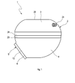
- an active silencer 1 comprises a housing 2, which is multi-shelled, preferably two-shelled and accordingly has at least one upper shell 3 and one lower shell 4.
- Upper shell 3 and lower shell 4 are each cup-shaped. Overall, this results in a substantially spherical shape for the housing. 2
- the silencer 1 contains in its housing 2 a sound-conducting body 5. This is designed funnel-shaped and has a connecting piece 6 and a flange portion 7. The connecting piece 6 is used to connect the silencer 1 to a room or to a line in which airborne sound propagates , which is to be actively damped by means of the muffler 1.
- the silencer 1 a loudspeaker 8, which has a conventional structure. Accordingly, the speaker 8 in a conventional manner to an electrodynamic transducer 9 which is fixed to a basket 10 and a membrane 11 can excite vibrations, which is clamped on the basket 10. On the speaker 8 also electrical connections 12 are provided, via which the speaker 8 is electrically operated.
- the sound-conducting body 5 is inserted into the lower shell 4.
- the lower shell 4 has an opening 13 through which the connecting piece 6 is led out of the housing 2.
- the connection piece 6 passes through the lower shell 4.
- the loudspeaker 8 is arranged in the upper shell 3 and fastened to the flange portion 7 on a side facing away from the connecting piece 6.
- the speaker 8 is mounted on the flange portion 7 such that thereby an unspecified here, enclosed by the flange portion 7, free inner cross section of the sound-conducting body 5 through the Loudspeaker 8 or through the membrane 11 is sealed gas-tight.
- a corresponding, not shown here, seal between the flange portion 7 and a rim 14 of the loudspeaker frame 10 may be arranged, with which the loudspeaker 8 is attached to the sound-conducting body 5.
- the housing 2 has a bypass 31, which bypasses the flange portion 7.
- the flange portion 7 to realize the bypass 31 a plurality of recesses 15.
- These recesses 15 form passage openings.
- an interior 16 of the upper shell 3 communicates with an inner space 17 of the lower shell 4.
- the inner space 16 of the upper shell 3 encloses the loudspeaker 8, while the inner space 17 of the lower shell 4 surrounds the sound-conducting body 5.
- the two interior spaces 16, 17 thus together form a rear volume for the loudspeaker 8. This rear volume is separated in a gas-tight manner from the interior of the sound-conducting body 5, whereby an acoustic short circuit is avoided.
- the sound-conducting body 5 can be expediently used as a drain for condensate that may arise during operation on the membrane 11 on the exhaust side.
- the flange portion 5 is arranged obliquely in its unspecified interior in the installed state, whereby it can flow down gravity due to gravity accumulating thereon.
- the connecting piece 6 has a longitudinal central axis 18, which is inclined by about 45 ° relative to a plane 19 in which the flange portion 7 is located. Inclination angle between this longitudinal central axis 18 and said plane 19 of 30 ° inclusive and including 60 ° allow a particularly compact design for the lower shell 4 and thus for the housing 2. In principle, however, inclination angles to 90 ° are conceivable.
- the trained in the interior of the sound-conducting body 5 sequence is preferably designed stepless and / or undercut. As a result, the accumulation of water or other liquid in the interior of the sound-conducting body 5 and thus inside the housing 2 can be avoided. The risk of ice formation within the muffler 1 is thereby reduced.
- the housing 2 is essentially spherical. This is achieved, for example, by comparatively small deviations in the dimensions of a width of the housing 2, a height of the housing 2 and a length of the housing 2 from each other.
- the width, height and length of the housing 2 are less than 30%, in particular less than 25% and preferably less than 20% from each other.
- Said cable connection 21 serves to carry electrical cables, not shown, for actuating the loudspeaker 8 through the housing 2.
- this cable connection 21 is designed so that in addition to the cable bushing also allows pressure equalization between the interior 16 of the upper shell 16 and an environment of the housing 2.
- the cable connection 21 is given a double function.
- Such a pressure equalization opening can be closed by means of a gas-permeable, but impermeable to liquid membrane.
- the muffler 1 can be additionally equipped with a suction tube, which allows extraction of condensate from the interior of the sound-conducting body 5.
- a suction tube which allows extraction of condensate from the interior of the sound-conducting body 5.
- the flange portion 7 has radially outwardly a plurality of projections 22. These are spaced apart in the circumferential direction and are radially opposite to the remaining flange portion 7 in front. About these projections 22, the axially inserted into the lower shell 4 sound-conducting body 5 can be supported radially on the outside of an unspecified inside of the lower shell 4. It is in principle possible to press the flange portion 7 in the lower shell 4, such that the said projections 22 are radially supported on the lower shell 4 with radial bias. This allows a purely frictional or non-positive fixation for the sound-conducting body 5 in or on the lower shell 4 can be realized.
- an edge portion 23 of the lower shell 4 with a stage, not shown here, at which the projections 22 can come to rest axially. In this way, a positive fixing of the sound-conducting body 5 in or on the lower shell 4 can be realized.
- the recesses 15 and the passage openings 15 are each arranged between two circumferentially adjacent projections 22 and formed by the distances between adjacent projections 22.
- the upper shell 3 is mounted axially on the lower shell 4.
- an edge portion 24 of the upper shell 3 overlaps the aforementioned edge portion 23 of the lower shell 4 radially outward.
- suitable quick-fastening means may be provided to fix the upper shell 3 to the lower shell 4.
- the upper shell 3 has in the example shown on a flat bottom portion 25.
- the dimensions of the upper shell 3 and the speaker 8 are coordinated so that the speaker 8 is supported in particular flat on the bottom portion 25 when the upper shell 3, the housing 2 closes.
- Corresponding Fig. 5 includes an exhaust system 26, which is only partially shown here and which is used in an internal combustion engine for discharging the exhaust gases, at least one such active muffler 1 and an exhaust-carrying line 27 on.
- the muffler 1 is connected with its connection piece 6 to the line 27.
- the exhaust pipe 27 on a connector 28 which is cut here or shown only half.
- the connector 28 is substantially Y-shaped and connects the conduit 27 to an end tube 29 and also allows the connection of the muffler 1.
- the muffler 1 is connected to the exhaust system 26 so that the connecting piece 6 substantially oriented in the same direction as an end 30 of the conduit 27. This allows a direct flow of hot exhaust gases into the connecting piece 6 and thus a direct exposure of the loudspeaker 8 with hot exhaust gases can be avoided.
- the muffler 1 is located relatively close to the tailpipe 29, so that this is a so-called rear muffler.
- the muffler 1 can be suitably mounted on a vehicle floor so that it is exposed to a wind.
- Vehicle floor flow guides are attached, which favor a direct admission of the housing 2 with wind.
- the assembly or arrangement of the muffler 1 on the exhaust system 26 is expediently such that the housing 2 maintains a predetermined minimum distance of about 10 mm to 20 mm with respect to an exhaust-carrying line, here opposite the exhaust pipe 27.
- the connecting piece 6 has a minimum length, which may be, for example, between 100 mm and 200 mm.
- the housing shells 3, 4 may be, for example, plastic parts. Likewise, this may be sheet metal parts made of metal.
- the sound-conducting body 5 is preferably a metal sheet metal part. Here, the sound-conducting body 5 may be composed of several individual parts. Likewise, a one-piece variant is conceivable. Particularly advantageous is an embodiment in which the housing 2 is assembled from exactly three or four parts, namely from the upper shell 3, the lower shell 4 and the sound-conducting body 5 and optionally the connecting piece 6. As a result, the housing 2 is extremely inexpensive.
Abstract
Description
Die vorliegende Erfindung betrifft einen aktiven Schalldämpfer für eine Abgasanlage einer Brennkraftmaschine, insbesondere eines Kraftfahrzeugs. Die Erfindung betrifft außerdem eine mit einem derartigen aktiven Schalldämpfer ausgestattete Abgasanlage für eine Brennkraftmaschine, insbesondere eines Kraftfahrzeugs.The present invention relates to an active silencer for an exhaust system of an internal combustion engine, in particular of a motor vehicle. The invention also relates to an exhaust system equipped with such an active silencer for an internal combustion engine, in particular a motor vehicle.
Aktive Schalldämpfer arbeiten mit Gegenschall, der mittels wenigstens eines Lautsprechers aktiv erzeugt wird und durch Phasenverschiebung zur Auslöschung bzw. Dämpfung bestimmter Frequenzen genutzt werden kann, bspw. um die Schallemission durch eine Abgasanlage einer Brennkraftmaschine in die Umgebung zu reduzieren.Active mufflers work with counter-sound, which is actively generated by means of at least one speaker and can be used by phase shift to extinguish or attenuate certain frequencies, eg. To reduce the noise emission by an exhaust system of an internal combustion engine into the environment.
Aktive Schalldämpfer sind bspw. aus der
Problematisch bei aktiven Schalldämpfern bei Abgasanlagen von Brennkraftmaschinen ist zum einen die thermische Belastung des Lautsprechers durch die hohen Abgastemperaturen. Während herkömmliche Lautsprecher in einem Bereich von 100°C bis 200°C arbeiten können, betragen die Abgastemperaturen für gewöhnlich 400°C bis 700°C. Es ist daher ein erhöhter Aufwand erforderlich, um eine Überhitzung des Lautsprechers zu vermeiden. Ferner kann bei der Verwendung aktiver Schalldämpfer bei Abgasanlagen von Brennkraftmaschinen das im Betrieb anfallende Kondensat problematisch sein. Die Abgase einer Brennkraftmaschine können relativ feucht sein, so dass es an Flächen, die relativ zum Abgas kühl sind, bspw. kälter als 100°C, zur Kondensatbildung kommt. Insbesondere kann sich somit an einer Membran eines Lautsprechers Kondensat bilden. Sich am Lautsprecher ansammelndes Kondensat kann die Membran belasten, die Wirkung des Lautsprechers erheblich beeinträchtigen und bei Frost einfrieren, was letztlich zu einer Zerstörung des Lautsprechers führen kann. Ferner benötigt ein Lautsprecher ein vergleichsweise großes Rückvolumen, insbesondere dann, wenn in einem tieffrequenten Bereich vergleichsweise hohe Schalldruckpegel erzeugt werden sollen. Die Unterbringung eines vergleichsweise großen Rückvolumens kann jedoch zu erheblichen Bauraumproblemen führen, insbesondere bei Abgasanlagen von Fahrzeugen.The problem with active mufflers in exhaust systems of internal combustion engines on the one hand, the thermal load of the speaker by the high exhaust gas temperatures. While conventional loudspeakers can operate in a range of 100 ° C to 200 ° C, exhaust temperatures are usually 400 ° C to 700 ° C. It is therefore an increased effort required to avoid overheating of the speaker. Furthermore, when using active muffler in exhaust systems of Internal combustion engine, the resulting condensate in operation be problematic. The exhaust gases of an internal combustion engine may be relatively moist, so that it comes to surfaces which are cool relative to the exhaust gas, for example. Colder than 100 ° C, to form condensate. In particular, condensate can thus form on a membrane of a loudspeaker. Condensate accumulating on the loudspeaker can stress the diaphragm, significantly affect the loudspeaker's effect and freeze it in frost, which can ultimately destroy the loudspeaker. Furthermore, a loudspeaker requires a comparatively large back volume, in particular if comparatively high sound pressure levels are to be generated in a low-frequency range. The placement of a relatively large return volume, however, can lead to considerable space problems, especially in exhaust systems of vehicles.
Die vorliegende Erfindung beschäftigt sich mit dem Problem, für einen aktiven Schalldämpfer der eingangs genannten Art sowie für eine damit ausgestattete Abgasanlage eine verbesserte Ausführungsform anzugeben, die sich insbesondere dadurch auszeichnet, dass die Gefahr einer Beschädigung des Schalldämpfers durch Überhitzung und/oder durch Kondensat reduziert ist, wobei außerdem ein vergleichsweise großes Rückvolumen realisiert werden soll.The present invention is concerned with the problem of providing for an active silencer of the type mentioned and for an exhaust system equipped therewith an improved embodiment, which is characterized in particular by the fact that the risk of damaging the silencer is reduced by overheating and / or condensate , in addition, a comparatively large back volume to be realized.
Dieses Problem wird erfindungsgemäß durch die Gegenstände der unabhängigen Ansprüche gelöst. Vorteilhafte Ausführungsformen sind Gegenstand der abhängigen Ansprüche.This problem is solved according to the invention by the subject matters of the independent claims. Advantageous embodiments are the subject of the dependent claims.
Die Erfindung beruht auf dem allgemeinen Gedanken, ein Gehäuse zur Unterbringung des Lautsprechers in Schalenbauweise mit zwei topfförmigen Schalen aufzubauen, wobei im Inneren des Gehäuses ein trichterförmiger Schall-Leitkörper untergebracht ist. Dieser Schall-Leitkörper ist einerseits mit einem Anschlussstutzen durch die Unterschale hindurch aus dem Gehäuse herausgeführt und dient andererseits zur Befestigung des Lautsprechers an einem Flanschabschnitt. Dabei ist ein den Flanschabschnitt umgehender Bypass vorgesehen, der eine kommunizierende Verbindung zwischen einem Innenraum der Oberschale und einem Innenraum der Unterschale ermöglicht. Somit bilden das Volumen des Unterschaleninnenraums außerhalb des Schall-Leitkörpers und das Volumen des Oberschaleninnenraums abgesehen vom Lautsprecher zusammen das Rückvolumen des Lautsprechers. Hierdurch kann bei einem vergleichsweise kompakten Aufbau ein relativ großes Rückvolumen für den Lautsprecher realisiert werden. Über den Schall-Leitkörper kann das heiße Abgas quasi von unten zur Membran des Lautsprechers gelangen, wodurch über den Schall-Leitkörper ein gewisser Mindestabstand realisiert wird, was eine direkte Beaufschlagung der Membran bzw. des Lautsprechers mit heißen Abgasen vermeidet. Gleichzeitig gewährleistet diese Einbausituation, dass Kondensat vergleichsweise einfach vom Lautsprecher bzw. von dessen Membran abfließen bzw. weggeführt werden kann, und zwar durch den Schall-Leitkörper. Die Anordnung des Lautsprechers zusammen mit dem Schall-Leitkörper in einem eigenen Gehäuse ermöglicht es außerdem, den aktiven Schalldämpfer besonders einfach an einer Abgasanlage so zu positionieren, dass eine Überhitzung des Lautsprechers vermieden werden kann. Beispielsweise lassen sich Mindestabstände von heißen, abgasführenden Leitungen besonders einfach einhalten. Darüber hinaus kann das Gehäuse am Fahrzeug besonders einfach so montiert werden, dass es im Betrieb des Fahrzeugs dem Fahrtwind ausgesetzt ist. Ferner bildet der Schalldämpfer eine unabhängig von der konkreten Einbausituation vorfertigbare Einheit, die quasi universell einsetzbar ist.The invention is based on the general idea to build a housing for housing the speaker in shell construction with two pot-shaped shells, wherein a funnel-shaped sound-conducting body is housed inside the housing. This sound-conducting body is on the one hand with a Connecting piece out through the lower shell out of the housing and on the other hand serves to attach the speaker to a flange. In this case, a bypass portion bypassing the bypass is provided, which allows a communicating connection between an interior of the upper shell and an inner space of the lower shell. Thus, the volume of the lower shell interior outside the sound conducting body and the volume of the upper shell interior apart from the loudspeaker together form the rear volume of the loudspeaker. This allows a relatively large back volume for the speaker can be realized in a relatively compact design. About the sound-conducting body, the hot exhaust gas can reach quasi from the bottom to the diaphragm of the speaker, whereby a certain minimum distance is realized on the sound-conducting body, which avoids direct exposure of the membrane or the speaker with hot exhaust gases. At the same time, this installation situation ensures that condensate can flow away relatively easily from the loudspeaker or from its membrane, or can be led away, through the sound-conducting body. The arrangement of the speaker together with the sound-conducting body in a separate housing also makes it particularly easy to position the active muffler on an exhaust system so that overheating of the speaker can be avoided. For example, minimum distances of hot, exhaust gas lines can be kept particularly simple. In addition, the housing can be easily mounted on the vehicle so that it is exposed to the wind during operation of the vehicle. Furthermore, the silencer forms a unit that can be prefabricated independently of the specific installation situation, which can be used virtually universally.
Besonders vorteilhaft ist eine Ausführungsform, bei welcher der Schall-Leitkörper im Einbauzustand des Schalldämpfers in seinem Inneren einen Ablauf bildet, der vom Flanschabschnitt zum Anschlussstutzen führt. Hierdurch kann Kondensat, das sich im Betrieb des Schalldämpfers, z. Bsp. abgasseitig an der Membran bilden kann, besonders einfach aus dem Schalldämpfer herausgeführt werden.Particularly advantageous is an embodiment in which the sound-conducting body in the installed state of the muffler forms a drain in its interior, which leads from the flange to the connection piece. This can cause condensate, in the operation of the muffler, z. Ex. Can form on the exhaust side of the membrane, particularly easy to be led out of the muffler.
Besagter Ablauf kann insbesondere stufenlos und/oder hinterschnittfrei ausgestaltet werden, wodurch auch die Ansammlung von Wasser im Schalldämpfer und somit eine damit einhergehende Vereisungsgefahr reduziert werden.Said process can be designed in particular stepless and / or undercut, whereby the accumulation of water in the muffler and thus a concomitant risk of icing can be reduced.
Besonders vorteilhaft ist eine Ausführungsform, bei welcher das Gehäuse näherungsweise kugelförmig gestaltet ist. Beispielsweise können die Hauptabmessungen, nämlich Breite, Höhe und Länge des Gehäuses um weniger als 30% oder weniger als 25% oder weniger als 20% voneinander abweichen. Diese im Wesentlichen kugelförmige Gestalt des Gehäuses ergibt bei vergleichsweise kleiner Oberfläche ein relativ großes Volumen im Inneren des Gehäuses, das insbesondere als Rückvolumen für den Lautsprecher genutzt werden kann.Particularly advantageous is an embodiment in which the housing is designed approximately spherical. For example, the main dimensions, namely width, height and length of the housing may differ by less than 30% or less than 25% or less than 20%. This substantially spherical shape of the housing results in a comparatively small surface, a relatively large volume in the interior of the housing, which can be used in particular as a back volume for the speaker.
Bei einer anderen vorteilhaften Ausführungsform kann vorgesehen sein, den Flanschabschnitt radial außen mit mehreren, in Umfangsrichtung voneinander beabstandeten, radial vorstehenden Vorsprüngen auszustatten, die sich radial außen an einer Innenseite der Unterschale abstützen. Diese Abstützung kann insbesondere durch Formschluss und/oder Reibschluss so ausgestaltet werden, dass zur Befestigung des Schall-Leitkörpers im Gehäuse keine zusätzlichen, separaten Befestigungselemente, wie z. Bsp. Schrauben, erforderlich sind. Hierdurch können Wärmebrücken zwischen dem Gehäuse und dem Schall-Leitkörper vermieden werden, was die Wärmeübertragung auf den Lautsprecher reduziert.In another advantageous embodiment can be provided to equip the flange radially outwardly with a plurality of circumferentially spaced apart, radially projecting projections, which are supported radially on the outside of an inner side of the lower shell. This support can be configured in particular by positive engagement and / or frictional engagement so that no additional, separate fasteners such. Ex. Screws are required. As a result, thermal bridges between the housing and the sound-conducting body can be avoided, which reduces the heat transfer to the speaker.
Weitere wichtige Merkmale und Vorteile der Erfindung ergeben sich aus den Unteransprüchen, aus den Zeichnungen und aus der zugehörigen Figurenbeschreibung anhand der Zeichnungen.Other important features and advantages of the invention will become apparent from the dependent claims, from the drawings and from the associated figure description with reference to the drawings.
Es versteht sich, dass die vorstehend genannten und die nachstehend noch zu erläuternden Merkmale nicht nur in der jeweils angegebenen Kombination, sondern auch in anderen Kombinationen oder in Alleinstellung verwendbar sind, ohne den Rahmen der vorliegenden Erfindung zu verlassen.It is understood that the features mentioned above and those yet to be explained below can be used not only in the particular combination given, but also in other combinations or in isolation, without departing from the scope of the present invention.
Bevorzugte Ausführungsbeispiele der Erfindung sind in den Zeichnungen dargestellt und werden in der nachfolgenden Beschreibung näher erläutert, wobei sich gleiche Bezugszeichen auf gleiche oder ähnliche oder funktional gleiche Bauteile beziehen.Preferred embodiments of the invention are illustrated in the drawings and will be described in more detail in the following description, wherein like reference numerals refer to the same or similar or functionally identical components.
- Fig. 1Fig. 1
- eine Seitenansicht eines aktiven Schalldämpfers,a side view of an active silencer,
- Fig. 2Fig. 2
-
eine Seitenansicht wie in
Fig. 1 , jedoch bei transparentem Gehäuse,a side view as inFig. 1 , but with transparent housing, - Fig. 3Fig. 3
- eine Ansicht von unten auf den Schalldämpfer bei fehlender Unterschale,a view from below of the muffler in the absence of a lower shell,
- Fig. 4Fig. 4
- eine perspektivische Ansicht des Schalldämpfers bei fehlender Oberschale,a perspective view of the muffler in the absence of upper shell,
- Fig. 5Fig. 5
- eine perspektivische Ansicht einer Abgasanlage mit dem Schalldämpfer bei weggelassener Oberschale eines Verbindungsstücks.a perspective view of an exhaust system with the muffler with omitted upper shell of a connector.
Entsprechend den
Der Schalldämpfer 1 enthält in seinem Gehäuse 2 einen Schall-Leitkörper 5. Dieser ist trichterförmig ausgestaltet und besitzt einen Anschlussstutzen 6 und einen Flanschabschnitt 7. Der Anschlussstutzen 6 dient zum Anschließen des Schalldämpfers 1 an einen Raum oder an eine Leitung, in der sich Luftschall ausbreitet, der mit Hilfe des Schalldämpfers 1 aktiv bedämpft werden soll.The
Für die aktive Schalldämpfung weist der Schalldämpfer 1 einen Lautsprecher 8 auf, der einen üblichen Aufbau besitzt. Dementsprechend weist der Lautsprecher 8 in üblicher Weise einen elektrodynamischen Wandler 9 auf, der an einem Korb 10 befestigt ist und eine Membran 11 zu Schwingungen anregen kann, die am Korb 10 aufgespannt ist. Am Lautsprecher 8 sind außerdem elektrische Anschlüsse 12 vorgesehen, über welche der Lautsprecher 8 elektrisch betätigbar ist.For the active silencing, the silencer 1 a
Der Schall-Leitkörper 5 ist in die Unterschale 4 eingesetzt. Die Unterschale 4 besitzt eine Öffnung 13, durch welche der Anschlussstutzen 6 aus dem Gehäuse 2 herausgeführt ist. Somit durchsetzt der Anschlussstutzen 6 die Unterschale 4. Im Unterschied dazu ist der Lautsprecher 8 in der Oberschale 3 angeordnet und an einer vom Anschlussstutzen 6 abgewandten Seite am Flanschabschnitt 7 befestigt. Dabei ist der Lautsprecher 8 am Flanschabschnitt 7 derart angebracht, dass dadurch ein hier nicht näher bezeichneter, vom Flanschabschnitt 7 umschlossener, freier Innenquerschnitt des Schall-Leitkörpers 5 durch den Lautsprecher 8 bzw. durch dessen Membran 11 gasdicht verschlossen ist. Hierzu kann eine entsprechende, hier nicht dargestellte, Dichtung zwischen dem Flanschabschnitt 7 und einem Rand 14 des Lautsprecherkorbs 10 angeordnet sein, mit dem der Lautsprecher 8 am Schall-Leitkörper 5 befestigt ist.The sound-conducting
Das Gehäuse 2 weist einen Bypass 31 auf, der den Flanschabschnitt 7 umgeht. Im gezeigten Beispiel weist der Flanschabschnitt 7 zur Realisierung des Bypasses 31 mehrere Ausnehmungen 15 auf. Diese Ausnehmungen 15 bilden Durchgangsöffnungen. Durch diese Durchgangsöffnungen 15 hindurch, also über den Bypass 31 ist ein Innenraum 16 der Oberschale 3 mit einem Innenraum 17 der Unterschale 4 kommunizierend verbunden. Der Innenraum 16 der Oberschale 3 umschließt dabei den Lautsprecher 8, während der Innenraum 17 der Unterschale 4 den Schall-Leitkörper 5 umschließt. Die beiden Innenräume 16, 17 bilden somit gemeinsam ein Rückvolumen für den Lautsprecher 8. Dieses Rückvolumen ist dabei gasdicht vom Inneren des Schall-Leitkörpers 5 getrennt, wodurch ein akustischer Kurzschluss vermieden wird.The
Der Schall-Leitkörper 5 kann zweckmäßig als Ablauf für Kondensat genutzt werden, dass im Betrieb an der Membran 11 an der Abgasseite entstehen kann. Hierzu ist der Flanschabschnitt 5 in seinem nicht näher bezeichneten Inneren im Einbauzustand schräg angeordnet, wodurch sich daran ansammelnde Flüssigkeit schwerkraftbedingt nach unten abfließen kann. Im Beispiel besitzt der Anschlussstutzen 6 eine Längsmittelachse 18, die gegenüber einer Ebene 19, in welcher der Flanschabschnitt 7 liegt, um etwa 45° geneigt ist. Neigungswinkel zwischen dieser Längsmittelachse 18 und besagter Ebene 19 von einschließlich 30° bis einschließlich 60° ermöglichen eine besonders kompakte Bauweise für die Unterschale 4 und somit für das Gehäuse 2. Grundsätzlich sind jedoch auch Neigungswinkel bis 90° denkbar.The sound-conducting
Der im Inneren des Schall-Leitkörpers 5 ausgebildete Ablauf ist vorzugsweise stufenlos und/oder hinterschnittfrei ausgestaltet. Hierdurch kann die Ansammlung von Wasser oder anderer Flüssigkeit im Inneren des Schall-Leitkörpers 5 und somit im Inneren des Gehäuses 2 vermieden werden. Die Gefahr einer Eisbildung innerhalb des Schalldämpfers 1 wird dadurch reduziert.The trained in the interior of the sound-conducting
Wie bereits erläutert ist das Gehäuse 2 im Wesentlichen kugelförmig gestaltet. Erreicht wird dies bspw. durch vergleichsweise geringe Abweichungen bei den Abmessungen einer Breite des Gehäuses 2, einer Höhe des Gehäuses 2 und einer Länge des Gehäuses 2 voneinander. Beispielsweise weichen Breite, Höhe und Länge des Gehäuses 2 um weniger als 30%, insbesondere um weniger als 25% und vorzugsweise um weniger als 20% voneinander ab. Desweiteren kann das Gehäuse 2 bezüglich einer Hochachse 20, die senkrecht auf der Flanschebene 19 steht, im Wesentlichen rotationssymmetrisch ausgestaltet sein. Diese Rotationssymmetrie endet bei der Unterschale 4 am Bereich der Öffnung 13 und an der Oberschale 3 im Bereich eines Kabelanschlusses 21. Besagter Kabelanschluss 21 dient dazu, nicht gezeigte elektrische Kabel zum Betätigen des Lautsprechers 8 durch das Gehäuse 2 durchzuführen. Besonders vorteilhaft ist dabei eine Ausgestaltung, bei welcher dieser Kabelanschluss 21 so ausgestaltet ist, dass er zusätzlich zur Kabeldurchführung außerdem einen Druckausgleich zwischen dem Innenraum 16 der Oberschale 16 und einer Umgebung des Gehäuses 2 ermöglicht. Hierdurch erhält der Kabelanschluss 21 eine Doppelfunktion. Alternativ ist es ebenso möglich, in der Oberschale 3 und/oder in der Unterschale 4 zumindest eine hier nicht dargestellte Druckausgleichsöffnung anzubringen, die insbesondere spritzwassergeschützt sein kann. Bspw. kann eine solche Druckausgleichsöffnung mit Hilfe einer gasdurchlässigen, jedoch für Flüssigkeit undurchlässigen Membran verschlossen sein.As already explained, the
Für den Fall, dass bei einer besonderen Einbausituation die Nutzung des Schall-Leitkörpers 5 als Ablauf nicht möglich sein sollte, kann der Schalldämpfer 1 zusätzlich mit einem Saugrohr ausgestattet werden, das eine Absaugung von Kondensat aus dem Inneren des Schall-Leitkörpers 5 ermöglicht. Eine derartige Ausführungsform ist hier jedoch nicht dargestellt.In the event that in a particular installation situation, the use of the sound-conducting
Der Flanschabschnitt 7 besitzt radial außen mehrere Vorsprünge 22. Diese sind in Umfangsrichtung voneinander beabstandet und stehen radial gegenüber dem übrigen Flanschabschnitt 7 vor. Über diese Vorsprünge 22 kann sich der axial in die Unterschale 4 eingesetzte Schall-Leitkörper 5 radial außen an einer nicht näher bezeichneten Innenseite der Unterschale 4 abstützen. Dabei ist es grundsätzlich möglich, den Flanschabschnitt 7 in die Unterschale 4 einzupressen, derart, dass sich die genannten Vorsprünge 22 mit radialer Vorspannung an der Unterschale 4 radial abstützen. Hierdurch kann eine rein reibschlüssige bzw. kraftschlüssige Fixierung für den Schall-Leitkörper 5 in bzw. an der Unterschale 4 realisiert werden. Zusätzlich oder alternativ ist es ebenso möglich, einen Randabschnitt 23 der Unterschale 4 mit einer hier nicht gezeigten Stufe zu versehen, an welcher die Vorsprünge 22 axial zur Anlage kommen können. Hierdurch kann eine formschlüssige Fixierung des Schall-Leitkörpers 5 in bzw. an der Unterschale 4 realisiert werden.The
Erkennbar sind zur Ausbildung des Bypasses 31 die Ausnehmungen 15 bzw. die Durchgangsöffnungen 15 jeweils zwischen zwei in Umfangsrichtung benachbarten Vorsprüngen 22 angeordnet bzw. durch die Abstände zwischen benachbarten Vorsprüngen 22 gebildet.Visible to the formation of the
Bei der hier gezeigten Ausführungsform ist die Oberschale 3 auf die Unterschale 4 axial aufgesteckt. Hierzu übergreift ein Randabschnitt 24 der Oberschale 3 den zuvor genannten Randabschnitt 23 der Unterschale 4 radial außen. Desweiteren können hier nicht gezeigte, geeignete Schnellbefestigungsmittel vorgesehen sein, um die Oberschale 3 an der Unterschale 4 zu fixieren.In the embodiment shown here, the
Die Oberschale 3 weist im gezeigten Beispiel einen ebenen Bodenabschnitt 25 auf. Zweckmäßig sind die Dimensionen der Oberschale 3 und des Lautsprechers 8 so aufeinander abgestimmt, dass der Lautsprecher 8 insbesondere flächig am Bodenabschnitt 25 abgestützt ist, wenn die Oberschale 3 das Gehäuse 2 verschließt.The
Entsprechend
Im gezeigten Beispiel befindet sich der Schalldämpfer 1 relativ nahe am Endrohr 29, so dass es sich hierbei um einen so genannten Nachschalldämpfer handelt. Der Schalldämpfer 1 kann an einem Fahrzeugboden zweckmäßig so montiert werden, dass er einem Fahrtwind ausgesetzt ist. Zusätzlich können am Fahrzeugboden Strömungsleitelemente angebracht werden, die eine direkte Beaufschlagung des Gehäuses 2 mit Fahrtwind begünstigen.In the example shown, the
Die Montage bzw. Anordnung des Schalldämpfers 1 an der Abgasanlage 26 erfolgt zweckmäßig so, dass das Gehäuse 2 einen vorbestimmten Mindestabstand von ca. 10 mm bis 20 mm gegenüber einer abgasführenden Leitung, hier gegenüber der Abgasleitung 27 einhält. Darüber hinaus besitzt der Anschlussstutzen 6 eine Mindestlänge, die bspw. zwischen 100 mm und 200 mm liegen kann. Durch diese Maßnahmen kann eine Überhitzung des Lautsprechers 8 vermieden werden.The assembly or arrangement of the
Bei den Gehäuseschalen 3, 4, kann es sich bspw. um Kunststoffteile handeln. Ebenso kann es sich hierbei um Blechformteile aus Metall handeln. Beim Schall-Leitkörper 5 handelt es sich bevorzugt um ein Blechformteil aus Metall. Hierbei kann der Schall-Leitkörper 5 aus mehreren Einzelteilen zusammengesetzt sein. Ebenso ist eine einstückig hergestellte Variante denkbar. Besonders vorteilhaft ist dabei eine Ausgestaltung, bei der das Gehäuse 2 aus genau drei oder vier Teilen zusammengebaut ist, nämlich aus der Oberschale 3, der Unterschale 4 und dem Schall-Leitkörper 5 sowie gegebenenfalls dem Anschlussstutzen 6. Hierdurch baut das Gehäuse 2 extrem preiswert.The
Claims (12)
dadurch gekennzeichnet,
dass der Bypass (31) durch Ausnehmungen (13) gebildet ist, die der Flanschabschnitt (7) aufweist.Silencer according to claim 1,
characterized,
in that the bypass (31) is formed by recesses (13) which the flange section (7) has.
dadurch gekennzeichnet,
dass der Schall-Leitkörper (5) im Einbauzustand des Schalldämpfers (1) in seinem Inneren einen vom Flanschabschnitt (7) zum Anschlussstutzen (6) führenden Ablauf bildet.Silencer according to claim 1 or 2,
characterized,
that the sound-conducting body (5) in the installed state of the muffler (1) in its interior forms a drain from the flange portion (7) to the connecting piece (6).
dadurch gekennzeichnet,
dass der Ablauf stufenlos und/oder hinterschnittfrei ausgestaltet ist.Silencer according to claim 3,
characterized,
that the sequence is designed stepless and / or undercut-free.
dadurch gekennzeichnet,
dass das Gehäuse (2) kugelförmig gestaltet ist, derart, dass Breite, Höhe und Länge des Gehäuses (2) weniger als 30% oder weniger als 20% voneinander abweichen.Silencer according to one of claims 1 to 4,
characterized,
that the housing (2) is designed spherical, such that the width, height and length of the housing (2) differ less than 30% or less than 20% from each other.
dadurch gekennzeichnet,
dass der Flanschabschnitt (7) außen mehrere in Umfangsrichtung voneinander beabstandete, radial vorstehende Vorsprünge (22) aufweist, die sich radial außen an einer Innenseite der Unterschale (4) abstützen.Silencer according to one of claims 1 to 5,
characterized,
in that the flange section (7) has a plurality of circumferentially spaced, radially projecting projections (22) which are supported radially on the outside of an inner side of the lower shell (4).
dadurch gekennzeichnet,
dass je eine der Ausnehmungen (15) zwischen zwei in Umfangsrichtung benachbarten Vorsprüngen (22) angeordnet ist.Silencer according to claims 2 and 6,
characterized,
that each one of the recesses (15) is disposed between two circumferentially adjacent projections (22).
dadurch gekennzeichnet,
dass der Flanschabschnitt (7) in die Unterschale (4) eingepresst ist, so dass sich die Vorsprünge (22) radial vorgespannt an der Unterschale (4) abstützen.Silencer according to claim 6 or 7,
characterized,
in that the flange section (7) is pressed into the lower shell (4) so that the projections (22) are supported on the lower shell (4) in a radially biased manner.
dadurch gekennzeichnet,
dass die Oberschale (3) mit einem Randabschnitt (24) außen auf einen Randabschnitt (23) der Unterschale (4) aufgesteckt ist.Silencer according to one of claims 1 to 8,
characterized,
in that the upper shell (3) is attached externally to an edge section (23) of the lower shell (4) with an edge section (24).
dadurch gekennzeichnet,
dass die Oberschale (3) einen ebenen Bodenabschnitt (25) aufweist, an dem der Lautsprecher (8) abgestützt ist.Silencer according to one of claims 1 to 9,
characterized,
in that the upper shell (3) has a flat bottom section (25) on which the loudspeaker (8) is supported.
dadurch gekennzeichnet,
dass die Oberschale (3) einen Kabelanschluss (21) aufweist, durch den Kabel zum elektrischen Betätigen des Lautsprechers (8) durchführbar sind und der so ausgestaltet ist, dass er einen Druckausgleich zwischen dem Innenraum (16) der Oberschale (3) und einer Umgebung des Gehäuses (2) ermöglicht.Silencer according to one of claims 1 to 10,
characterized,
in that the upper shell (3) has a cable connection (21) through which cables for electrically actuating the loudspeaker (8) can be made and which is designed such that it balances the pressure between the inner space (16) of the upper shell (3) and an environment of the housing (2) allows.
Applications Claiming Priority (1)
| Application Number | Priority Date | Filing Date | Title |
|---|---|---|---|
| DE102008018085A DE102008018085A1 (en) | 2008-04-09 | 2008-04-09 | Active muffler |
Publications (2)
| Publication Number | Publication Date |
|---|---|
| EP2108791A1 true EP2108791A1 (en) | 2009-10-14 |
| EP2108791B1 EP2108791B1 (en) | 2010-12-01 |
Family
ID=40681536
Family Applications (1)
| Application Number | Title | Priority Date | Filing Date |
|---|---|---|---|
| EP09155683A Active EP2108791B1 (en) | 2008-04-09 | 2009-03-20 | Active silencer |
Country Status (6)
| Country | Link |
|---|---|
| US (1) | US7891463B2 (en) |
| EP (1) | EP2108791B1 (en) |
| JP (1) | JP5325642B2 (en) |
| CN (1) | CN101555818B (en) |
| AT (1) | ATE490398T1 (en) |
| DE (2) | DE102008018085A1 (en) |
Cited By (5)
| Publication number | Priority date | Publication date | Assignee | Title |
|---|---|---|---|---|
| WO2011095412A1 (en) * | 2010-02-05 | 2011-08-11 | J. Eberspächer GmbH & Co. KG | Exhaust-gas system |
| EP2607640A1 (en) * | 2011-12-20 | 2013-06-26 | Bayerische Motoren Werke Aktiengesellschaft | Actuator assembly for active exhaust systems and method for operating the same |
| DE102013011937B3 (en) * | 2013-07-17 | 2014-10-09 | Eberspächer Exhaust Technology GmbH & Co. KG | Sound generator for an anti-noise system for influencing exhaust noise and / or Ansauggeräuschen a motor vehicle |
| EP2801708A1 (en) | 2013-05-08 | 2014-11-12 | Eberspächer Exhaust Technology GmbH & Co. KG | Sound Generator for an Anti-noise System for influencing exhaust Noises and/or intake Noises of a Motor Vehicle |
| EP2800090A3 (en) * | 2013-05-03 | 2015-04-15 | Eberspächer Exhaust Technology GmbH & Co. KG | Sound generator for an exhaust system |
Families Citing this family (31)
| Publication number | Priority date | Publication date | Assignee | Title |
|---|---|---|---|---|
| DE102009031848A1 (en) * | 2009-07-03 | 2011-01-05 | J. Eberspächer GmbH & Co. KG | Exhaust system with active silencer |
| DE102009032553A1 (en) * | 2009-07-10 | 2011-01-20 | J. Eberspächer GmbH & Co. KG | Exhaust system and associated connection arrangement for an actuator |
| DE102009049280B4 (en) | 2009-10-13 | 2016-10-06 | Eberspächer Exhaust Technology GmbH & Co. KG | Active muffler |
| DE102010062049A1 (en) * | 2010-11-26 | 2012-05-31 | J. Eberspächer GmbH & Co. KG | silencer |
| FR2972022B1 (en) | 2011-02-25 | 2013-03-15 | Peugeot Citroen Automobiles Sa | MOTOR VEHICLE HAVING AN EXHAUST LINE WITH ACOUSTIC MEANS ARRANGED IN FRONT OF THE REAR TRAIN |
| DE102011018459A1 (en) | 2011-04-21 | 2012-10-25 | J. Eberspächer GmbH & Co. KG | Übertragungsstreckenkompensator |
| DE202012012724U1 (en) | 2011-06-01 | 2013-09-11 | Eberspächer Exhaust Technology GmbH & Co. KG | Anti-noise system for exhaust systems |
| DE102011106647A1 (en) | 2011-07-05 | 2013-01-10 | J. Eberspächer GmbH & Co. KG | ANTISCHALL SYSTEM FOR EXHAUST SYSTEMS AND METHOD FOR CONTROLLING THE SAME |
| DE102011084567C5 (en) * | 2011-10-14 | 2019-08-14 | Eberspächer Exhaust Technology GmbH & Co. KG | Active muffler |
| DE102011116635A1 (en) * | 2011-10-20 | 2013-04-25 | Audi Ag | Warning system for softly-moving motor vehicle to warn other road users, has acoustic signal generating device with loudspeaker, which is arranged in exhaust system of internal combustion engine |
| DE102011117495B4 (en) | 2011-11-02 | 2014-08-21 | Eberspächer Exhaust Technology GmbH & Co. KG | Overload protection for loudspeakers in exhaust systems |
| US9386366B2 (en) | 2011-12-02 | 2016-07-05 | Eberspächer Exhaust Technology GmbH & Co. KG | Active design of exhaust sounds |
| DE102012201725B4 (en) * | 2012-02-06 | 2016-02-25 | Eberspächer Exhaust Technology GmbH & Co. KG | Active muffler |
| DE102012018320B4 (en) * | 2012-09-15 | 2023-03-02 | Audi Ag | Exhaust system of an internal combustion engine and method for operating an exhaust system |
| DE102012109872B4 (en) | 2012-10-16 | 2015-08-27 | Eberspächer Exhaust Technology GmbH & Co. KG | Speakers with improved thermal capacity |
| DE102013104307A1 (en) | 2013-04-26 | 2014-10-30 | Eberspächer Exhaust Technology GmbH & Co. KG | System for influencing exhaust noise and / or intake noise and / or engine noise |
| EP2797075B1 (en) | 2013-04-26 | 2018-09-12 | Eberspächer Exhaust Technology GmbH & Co. KG | System for influencing exhaust noise, engine noise and/or intake noise |
| DE102013208098A1 (en) * | 2013-05-03 | 2014-11-06 | Eberspächer Exhaust Technology GmbH & Co. KG | road vehicle |
| DE102013010609B4 (en) | 2013-06-25 | 2023-07-27 | Purem GmbH | System for influencing exhaust noise in a multi-flow exhaust system and motor vehicle |
| DE102014109780A1 (en) | 2013-08-02 | 2015-02-05 | Tenneco Gmbh | Sound system for a car |
| DE102013217849A1 (en) * | 2013-09-06 | 2015-03-12 | Friedrich Boysen Gmbh & Co. Kg | Active sound generating device |
| DE102013113803A1 (en) | 2013-12-10 | 2015-06-11 | Eberspächer Exhaust Technology GmbH & Co. KG | Sound generator for a system for influencing exhaust noise of a motor vehicle |
| DE102014101826B4 (en) | 2014-02-13 | 2016-08-04 | Tenneco Gmbh | Sounder system for a motor vehicle |
| JP2015172370A (en) | 2014-03-04 | 2015-10-01 | エーバーシュペッヒャー・エグゾースト・テクノロジー・ゲーエムベーハー・ウント・コンパニー・カーゲー | active design of exhaust sound |
| WO2016005580A1 (en) | 2014-07-11 | 2016-01-14 | Tenneco Gmbh | Sound system for a motor vehicle |
| DE102015119191A1 (en) | 2015-11-06 | 2017-05-11 | Eberspächer Exhaust Technology GmbH & Co. KG | Sound generator for attachment to a vehicle for influencing noises of the vehicle |
| US9624799B1 (en) * | 2016-02-18 | 2017-04-18 | Schlumberger Technology Corporation | Multi-muffler sound attenuator assembly |
| DE102016002449A1 (en) * | 2016-02-27 | 2017-08-31 | Audi Ag | Motor vehicle with a control device for at least one speaker of an exhaust system of the motor vehicle |
| TWI567292B (en) * | 2016-03-16 | 2017-01-21 | 中原大學 | Waste air exhaustingdevice having functionalityto abatenoise and modulate noise frequency |
| DE102016107069A1 (en) * | 2016-04-15 | 2017-10-19 | Faurecia Emissions Control Technologies, Germany Gmbh | Sound generating device on a vehicle for reducing or generating engine sound and exhaust system |
| US10358956B1 (en) | 2018-07-09 | 2019-07-23 | Faurecia Emissions Control Technologies, Usa, Llc | Exhaust valve and active noise control for compact exhaust system |
Citations (17)
| Publication number | Priority date | Publication date | Assignee | Title |
|---|---|---|---|---|
| US4177874A (en) | 1977-04-01 | 1979-12-11 | Agence Nationale De Valorisation De La Recherche (Anvar) | Active acoustic sound absorber device |
| EP0373188A1 (en) | 1988-02-19 | 1990-06-20 | Noise Cancellation Tech | Exhaust gas muffler arrangement for combustion engine. |
| US5229556A (en) | 1990-04-25 | 1993-07-20 | Ford Motor Company | Internal ported band pass enclosure for sound cancellation |
| US5233137A (en) | 1990-04-25 | 1993-08-03 | Ford Motor Company | Protective anc loudspeaker membrane |
| US5336856A (en) | 1992-07-07 | 1994-08-09 | Arvin Industries, Inc. | Electronic muffler assembly with exhaust bypass |
| US5343533A (en) | 1992-04-06 | 1994-08-30 | Ford Motor Company | Transducer flux optimization |
| US5432857A (en) | 1990-04-25 | 1995-07-11 | Ford Motor Company | Dual bandpass secondary source |
| EP0674097A1 (en) | 1994-02-22 | 1995-09-27 | ELECTRONIC SOUND ATTENUATION S.p.A. | Active exhaust gas muffler |
| EP0755045A2 (en) | 1995-07-20 | 1997-01-22 | NOKIA TECHNOLOGY GmbH | Sound wave cancellation arrangement |
| US5600106A (en) | 1994-05-24 | 1997-02-04 | Noise Cancellation Technologies, Inc. | Actively sound reduced muffler having a venturi effect configuration |
| US5619020A (en) | 1991-08-29 | 1997-04-08 | Noise Cancellation Technologies, Inc. | Muffler |
| EP0916817A2 (en) | 1997-11-18 | 1999-05-19 | LEISTRITZ AG & CO. Abgastechnik | Active silencer |
| DE19751596A1 (en) | 1997-11-21 | 1999-06-02 | Leistritz Abgastech | Active noise damper for automobile exhaust |
| EP0939393A2 (en) * | 1998-02-27 | 1999-09-01 | Tenneco Automotive Inc. | Modular active silencer with port dish |
| EP1055804A1 (en) | 1999-05-19 | 2000-11-29 | LEISTRITZ AG & CO. Abgastechnik | Active exhaust silencer |
| EP1627996A1 (en) | 2004-08-19 | 2006-02-22 | J. Eberspächer GmbH & Co. KG | Active exhaust silencer |
| DE102006042224B3 (en) * | 2006-09-06 | 2008-01-17 | J. Eberspächer GmbH & Co. KG | Active sound absorber for exhaust-gas system of internal-combustion engine particularly in motor vehicle, has anti sound generator comprises membrane drive, with which anti sound generator is coupled with external wall of sound absorber |
Family Cites Families (24)
| Publication number | Priority date | Publication date | Assignee | Title |
|---|---|---|---|---|
| JPS6022010A (en) | 1983-07-18 | 1985-02-04 | Nissan Motor Co Ltd | Exhaust noise reducing device |
| US5044464A (en) * | 1990-01-23 | 1991-09-03 | Nelson Industries, Inc. | Active acoustic attenuation mixing chamber |
| JPH0419313A (en) * | 1990-05-11 | 1992-01-23 | Nissan Motor Co Ltd | Silencer for exhaust system in automobile |
| US5255321A (en) * | 1990-12-05 | 1993-10-19 | Harman International Industries, Inc. | Acoustic transducer for automotive noise cancellation |
| JPH0660716U (en) * | 1993-01-28 | 1994-08-23 | カルソニック株式会社 | Active acoustic reduction device |
| JP2597565Y2 (en) * | 1993-06-18 | 1999-07-05 | 富士通テン株式会社 | Muffler using movable noise canceling speaker |
| CZ284565B6 (en) * | 1993-07-07 | 1999-01-13 | Leistritz Ag & Co Abgastechnik | Active sound silencer |
| US5446249A (en) * | 1993-07-13 | 1995-08-29 | Digisonix, Inc. | Dry acoustic system preventing condensation |
| JP2587683Y2 (en) * | 1993-08-12 | 1998-12-24 | カルソニック株式会社 | Active silencer |
| DE4342133A1 (en) * | 1993-12-10 | 1995-06-14 | Nokia Deutschland Gmbh | Arrangement for active noise reduction |
| US6160892A (en) * | 1993-12-30 | 2000-12-12 | Bbn Corporation | Active muffler |
| US5513266A (en) * | 1994-04-29 | 1996-04-30 | Digisonix, Inc. | Integral active and passive silencer |
| US5541373A (en) * | 1994-09-06 | 1996-07-30 | Digisonix, Inc. | Active exhaust silencer |
| US5693918A (en) * | 1994-09-06 | 1997-12-02 | Digisonix, Inc. | Active exhaust silencer |
| JPH0988546A (en) * | 1995-09-28 | 1997-03-31 | Shinko Electric Co Ltd | Muffler |
| US5828759A (en) * | 1995-11-30 | 1998-10-27 | Siemens Electric Limited | System and method for reducing engine noise |
| JPH10143169A (en) * | 1996-11-14 | 1998-05-29 | Shinko Electric Co Ltd | Muffler |
| JPH1124672A (en) * | 1997-07-03 | 1999-01-29 | Shinko Electric Co Ltd | Muffler |
| US6005957A (en) * | 1998-02-27 | 1999-12-21 | Tenneco Automotive Inc. | Loudspeaker pressure plate |
| JP4340370B2 (en) * | 2000-02-21 | 2009-10-07 | ヤンマー株式会社 | Active silencer |
| US6684977B2 (en) * | 2001-09-13 | 2004-02-03 | Siemens Vdo Automotive, Inc. | Speaker retention assembly for an active noise control system |
| DE102005011747B3 (en) * | 2005-03-11 | 2006-06-29 | Benteler Automobiltechnik Gmbh | Active exhaust gas silencer for motor vehicle has membrane set in flexural oscillations by excitation by converter so that on surface facing exhaust gas flow structure-borne noise tuned to exhaust gas noise is created |
| DE102006010558A1 (en) * | 2006-03-06 | 2007-09-13 | J. Eberspächer GmbH & Co. KG | Active silencer for an exhaust system |
| JP2007291946A (en) * | 2006-04-25 | 2007-11-08 | Honda Motor Co Ltd | Exhaust control valve |
-
2008
- 2008-04-09 DE DE102008018085A patent/DE102008018085A1/en not_active Withdrawn
-
2009
- 2009-03-20 DE DE502009000203T patent/DE502009000203D1/en active Active
- 2009-03-20 EP EP09155683A patent/EP2108791B1/en active Active
- 2009-03-20 AT AT09155683T patent/ATE490398T1/en active
- 2009-04-03 CN CN2009101300318A patent/CN101555818B/en active Active
- 2009-04-09 JP JP2009094878A patent/JP5325642B2/en active Active
- 2009-04-09 US US12/421,003 patent/US7891463B2/en active Active
Patent Citations (17)
| Publication number | Priority date | Publication date | Assignee | Title |
|---|---|---|---|---|
| US4177874A (en) | 1977-04-01 | 1979-12-11 | Agence Nationale De Valorisation De La Recherche (Anvar) | Active acoustic sound absorber device |
| EP0373188A1 (en) | 1988-02-19 | 1990-06-20 | Noise Cancellation Tech | Exhaust gas muffler arrangement for combustion engine. |
| US5229556A (en) | 1990-04-25 | 1993-07-20 | Ford Motor Company | Internal ported band pass enclosure for sound cancellation |
| US5233137A (en) | 1990-04-25 | 1993-08-03 | Ford Motor Company | Protective anc loudspeaker membrane |
| US5432857A (en) | 1990-04-25 | 1995-07-11 | Ford Motor Company | Dual bandpass secondary source |
| US5619020A (en) | 1991-08-29 | 1997-04-08 | Noise Cancellation Technologies, Inc. | Muffler |
| US5343533A (en) | 1992-04-06 | 1994-08-30 | Ford Motor Company | Transducer flux optimization |
| US5336856A (en) | 1992-07-07 | 1994-08-09 | Arvin Industries, Inc. | Electronic muffler assembly with exhaust bypass |
| EP0674097A1 (en) | 1994-02-22 | 1995-09-27 | ELECTRONIC SOUND ATTENUATION S.p.A. | Active exhaust gas muffler |
| US5600106A (en) | 1994-05-24 | 1997-02-04 | Noise Cancellation Technologies, Inc. | Actively sound reduced muffler having a venturi effect configuration |
| EP0755045A2 (en) | 1995-07-20 | 1997-01-22 | NOKIA TECHNOLOGY GmbH | Sound wave cancellation arrangement |
| EP0916817A2 (en) | 1997-11-18 | 1999-05-19 | LEISTRITZ AG & CO. Abgastechnik | Active silencer |
| DE19751596A1 (en) | 1997-11-21 | 1999-06-02 | Leistritz Abgastech | Active noise damper for automobile exhaust |
| EP0939393A2 (en) * | 1998-02-27 | 1999-09-01 | Tenneco Automotive Inc. | Modular active silencer with port dish |
| EP1055804A1 (en) | 1999-05-19 | 2000-11-29 | LEISTRITZ AG & CO. Abgastechnik | Active exhaust silencer |
| EP1627996A1 (en) | 2004-08-19 | 2006-02-22 | J. Eberspächer GmbH & Co. KG | Active exhaust silencer |
| DE102006042224B3 (en) * | 2006-09-06 | 2008-01-17 | J. Eberspächer GmbH & Co. KG | Active sound absorber for exhaust-gas system of internal-combustion engine particularly in motor vehicle, has anti sound generator comprises membrane drive, with which anti sound generator is coupled with external wall of sound absorber |
Cited By (13)
| Publication number | Priority date | Publication date | Assignee | Title |
|---|---|---|---|---|
| CN102741512B (en) * | 2010-02-05 | 2015-06-17 | 埃贝赫排气科技有限两合公司 | Exhaust-gas system |
| CN102741512A (en) * | 2010-02-05 | 2012-10-17 | 埃贝赫有限两合公司 | Exhaust-gas system |
| WO2011095412A1 (en) * | 2010-02-05 | 2011-08-11 | J. Eberspächer GmbH & Co. KG | Exhaust-gas system |
| EP2607640A1 (en) * | 2011-12-20 | 2013-06-26 | Bayerische Motoren Werke Aktiengesellschaft | Actuator assembly for active exhaust systems and method for operating the same |
| US9462363B2 (en) | 2013-05-03 | 2016-10-04 | Eberspächer Exhaust Technology GmbH & Co. KG | Sound generator for an exhaust system |
| EP2800090A3 (en) * | 2013-05-03 | 2015-04-15 | Eberspächer Exhaust Technology GmbH & Co. KG | Sound generator for an exhaust system |
| EP2801708A1 (en) | 2013-05-08 | 2014-11-12 | Eberspächer Exhaust Technology GmbH & Co. KG | Sound Generator for an Anti-noise System for influencing exhaust Noises and/or intake Noises of a Motor Vehicle |
| DE102013104810A1 (en) | 2013-05-08 | 2014-11-13 | Eberspächer Exhaust Technology GmbH & Co. KG | VEHICLE GENERATOR FOR AN ANTI-VALL SYSTEM FOR INFLUENCING EXHAUST VACUUM AND / OR INTAKE NOISE OF A MOTOR VEHICLE |
| US9374632B2 (en) | 2013-05-08 | 2016-06-21 | Eberspächer Exhaust Technology GmbH & Co. KG | Sound generator for an anti-noise system for influencing exhaust noises and/or intake noises of a motor vehicle |
| DE102013011937B3 (en) * | 2013-07-17 | 2014-10-09 | Eberspächer Exhaust Technology GmbH & Co. KG | Sound generator for an anti-noise system for influencing exhaust noise and / or Ansauggeräuschen a motor vehicle |
| US9066168B2 (en) | 2013-07-17 | 2015-06-23 | Eberspächer Exhaust Technology GmbH & Co. KG | Sound generator for an anti-noise system for influencing exhaust noise and/or intake noise of a motor vehicle |
| JP2015042865A (en) * | 2013-07-17 | 2015-03-05 | エーバーシュペッヒャー・エグゾースト・テクノロジー・ゲーエムベーハー・ウント・コンパニー・カーゲー | Sound generator for anti-noise system for influencing exhaust noise and/or intake noise of motor vehicle |
| EP2826966A1 (en) | 2013-07-17 | 2015-01-21 | Eberspächer Exhaust Technology GmbH & Co. KG | Sound Generator for an Anti-Noise System for influencing exhaust Noise and/or intake Noise of a Motor Vehicle |
Also Published As
| Publication number | Publication date |
|---|---|
| US20090255754A1 (en) | 2009-10-15 |
| US7891463B2 (en) | 2011-02-22 |
| DE502009000203D1 (en) | 2011-01-13 |
| JP2009250244A (en) | 2009-10-29 |
| EP2108791B1 (en) | 2010-12-01 |
| ATE490398T1 (en) | 2010-12-15 |
| DE102008018085A1 (en) | 2009-10-15 |
| JP5325642B2 (en) | 2013-10-23 |
| CN101555818B (en) | 2011-08-31 |
| CN101555818A (en) | 2009-10-14 |
Similar Documents
| Publication | Publication Date | Title |
|---|---|---|
| EP2108791B1 (en) | Active silencer | |
| DE102009049280B4 (en) | Active muffler | |
| EP1898059B1 (en) | Active silencer for an exhaust system | |
| EP2354483B1 (en) | Exhaust muffler | |
| EP2623737B1 (en) | Active silencer | |
| EP1055804B1 (en) | Active exhaust silencer | |
| EP2233708A1 (en) | Exhaust treatment device | |
| EP1832725B1 (en) | Active silencer for an exhaust system | |
| WO2012168039A1 (en) | Silencer and a method for producing same | |
| EP0707737A1 (en) | Active sound damper | |
| DE102013217849A1 (en) | Active sound generating device | |
| EP3009623B1 (en) | Component of an exhaust system and mounting of that component | |
| EP3728824A1 (en) | Broad-band silencer for a motor vehicle engine | |
| WO2016045661A1 (en) | Heating device exhaust gas arrangement with integrated sound suppressor and method for producing same | |
| DE102012204114B4 (en) | Muffler unit | |
| DE112007000864T5 (en) | Exhaust manifold assembly | |
| EP3173595B1 (en) | Silencer | |
| EP3032063B1 (en) | Exhaust pipe | |
| DE112013004789T5 (en) | Exhaust gas component with a vibration-insulated pipe | |
| DE2309571A1 (en) | EXHAUST SILENCER FOR TWO-STROKE ENGINES | |
| DE10102923C1 (en) | Engine silencer, for vehicle, has at least one membrane and body sound transmission devices acting with membrane and body component | |
| DE10131475B4 (en) | exhaust silencer | |
| DE19953995A1 (en) | Exhaust gas system with heat screening for vehicle including exhaust gas conducting element and heat screening to be arranged between exhaust gas conducting element and bodywork of vehicle spaced at distance from exhaust conducting element | |
| EP2463492A1 (en) | Housing | |
| DE10332941B4 (en) | Exhaust system of an internal combustion engine for a motor vehicle |
Legal Events
| Date | Code | Title | Description |
|---|---|---|---|
| PUAI | Public reference made under article 153(3) epc to a published international application that has entered the european phase |
Free format text: ORIGINAL CODE: 0009012 |
|
| AK | Designated contracting states |
Kind code of ref document: A1 Designated state(s): AT BE BG CH CY CZ DE DK EE ES FI FR GB GR HR HU IE IS IT LI LT LU LV MC MK MT NL NO PL PT RO SE SI SK TR |
|
| AX | Request for extension of the european patent |
Extension state: AL BA RS |
|
| 17P | Request for examination filed |
Effective date: 20100414 |
|
| AKX | Designation fees paid |
Designated state(s): AT BE BG CH CY CZ DE DK EE ES FI FR GB GR HR HU IE IS IT LI LT LU LV MC MK MT NL NO PL PT RO SE SI SK TR |
|
| GRAP | Despatch of communication of intention to grant a patent |
Free format text: ORIGINAL CODE: EPIDOSNIGR1 |
|
| GRAC | Information related to communication of intention to grant a patent modified |
Free format text: ORIGINAL CODE: EPIDOSCIGR1 |
|
| GRAS | Grant fee paid |
Free format text: ORIGINAL CODE: EPIDOSNIGR3 |
|
| GRAA | (expected) grant |
Free format text: ORIGINAL CODE: 0009210 |
|
| AK | Designated contracting states |
Kind code of ref document: B1 Designated state(s): AT BE BG CH CY CZ DE DK EE ES FI FR GB GR HR HU IE IS IT LI LT LU LV MC MK MT NL NO PL PT RO SE SI SK TR |
|
| REG | Reference to a national code |
Ref country code: GB Ref legal event code: FG4D Free format text: NOT ENGLISH |
|
| REG | Reference to a national code |
Ref country code: CH Ref legal event code: EP |
|
| REG | Reference to a national code |
Ref country code: IE Ref legal event code: FG4D |
|
| REF | Corresponds to: |
Ref document number: 502009000203 Country of ref document: DE Date of ref document: 20110113 Kind code of ref document: P |
|
| REG | Reference to a national code |
Ref country code: SE Ref legal event code: TRGR |
|
| REG | Reference to a national code |
Ref country code: NL Ref legal event code: VDEP Effective date: 20101201 |
|
| PG25 | Lapsed in a contracting state [announced via postgrant information from national office to epo] |
Ref country code: NO Free format text: LAPSE BECAUSE OF FAILURE TO SUBMIT A TRANSLATION OF THE DESCRIPTION OR TO PAY THE FEE WITHIN THE PRESCRIBED TIME-LIMIT Effective date: 20110301 Ref country code: LT Free format text: LAPSE BECAUSE OF FAILURE TO SUBMIT A TRANSLATION OF THE DESCRIPTION OR TO PAY THE FEE WITHIN THE PRESCRIBED TIME-LIMIT Effective date: 20101201 |
|
| LTIE | Lt: invalidation of european patent or patent extension |
Effective date: 20101201 |
|
| PG25 | Lapsed in a contracting state [announced via postgrant information from national office to epo] |
Ref country code: HR Free format text: LAPSE BECAUSE OF FAILURE TO SUBMIT A TRANSLATION OF THE DESCRIPTION OR TO PAY THE FEE WITHIN THE PRESCRIBED TIME-LIMIT Effective date: 20101201 Ref country code: CY Free format text: LAPSE BECAUSE OF FAILURE TO SUBMIT A TRANSLATION OF THE DESCRIPTION OR TO PAY THE FEE WITHIN THE PRESCRIBED TIME-LIMIT Effective date: 20101201 Ref country code: LV Free format text: LAPSE BECAUSE OF FAILURE TO SUBMIT A TRANSLATION OF THE DESCRIPTION OR TO PAY THE FEE WITHIN THE PRESCRIBED TIME-LIMIT Effective date: 20101201 Ref country code: NL Free format text: LAPSE BECAUSE OF FAILURE TO SUBMIT A TRANSLATION OF THE DESCRIPTION OR TO PAY THE FEE WITHIN THE PRESCRIBED TIME-LIMIT Effective date: 20101201 Ref country code: FI Free format text: LAPSE BECAUSE OF FAILURE TO SUBMIT A TRANSLATION OF THE DESCRIPTION OR TO PAY THE FEE WITHIN THE PRESCRIBED TIME-LIMIT Effective date: 20101201 Ref country code: SI Free format text: LAPSE BECAUSE OF FAILURE TO SUBMIT A TRANSLATION OF THE DESCRIPTION OR TO PAY THE FEE WITHIN THE PRESCRIBED TIME-LIMIT Effective date: 20101201 Ref country code: BG Free format text: LAPSE BECAUSE OF FAILURE TO SUBMIT A TRANSLATION OF THE DESCRIPTION OR TO PAY THE FEE WITHIN THE PRESCRIBED TIME-LIMIT Effective date: 20110301 |
|
| REG | Reference to a national code |
Ref country code: IE Ref legal event code: FD4D |
|
| PG25 | Lapsed in a contracting state [announced via postgrant information from national office to epo] |
Ref country code: GR Free format text: LAPSE BECAUSE OF FAILURE TO SUBMIT A TRANSLATION OF THE DESCRIPTION OR TO PAY THE FEE WITHIN THE PRESCRIBED TIME-LIMIT Effective date: 20110302 |
|
| PG25 | Lapsed in a contracting state [announced via postgrant information from national office to epo] |
Ref country code: CZ Free format text: LAPSE BECAUSE OF FAILURE TO SUBMIT A TRANSLATION OF THE DESCRIPTION OR TO PAY THE FEE WITHIN THE PRESCRIBED TIME-LIMIT Effective date: 20101201 Ref country code: EE Free format text: LAPSE BECAUSE OF FAILURE TO SUBMIT A TRANSLATION OF THE DESCRIPTION OR TO PAY THE FEE WITHIN THE PRESCRIBED TIME-LIMIT Effective date: 20101201 Ref country code: IE Free format text: LAPSE BECAUSE OF FAILURE TO SUBMIT A TRANSLATION OF THE DESCRIPTION OR TO PAY THE FEE WITHIN THE PRESCRIBED TIME-LIMIT Effective date: 20101201 Ref country code: PT Free format text: LAPSE BECAUSE OF FAILURE TO SUBMIT A TRANSLATION OF THE DESCRIPTION OR TO PAY THE FEE WITHIN THE PRESCRIBED TIME-LIMIT Effective date: 20110401 Ref country code: IS Free format text: LAPSE BECAUSE OF FAILURE TO SUBMIT A TRANSLATION OF THE DESCRIPTION OR TO PAY THE FEE WITHIN THE PRESCRIBED TIME-LIMIT Effective date: 20110401 Ref country code: ES Free format text: LAPSE BECAUSE OF FAILURE TO SUBMIT A TRANSLATION OF THE DESCRIPTION OR TO PAY THE FEE WITHIN THE PRESCRIBED TIME-LIMIT Effective date: 20110312 |
|
| PG25 | Lapsed in a contracting state [announced via postgrant information from national office to epo] |
Ref country code: SK Free format text: LAPSE BECAUSE OF FAILURE TO SUBMIT A TRANSLATION OF THE DESCRIPTION OR TO PAY THE FEE WITHIN THE PRESCRIBED TIME-LIMIT Effective date: 20101201 Ref country code: PL Free format text: LAPSE BECAUSE OF FAILURE TO SUBMIT A TRANSLATION OF THE DESCRIPTION OR TO PAY THE FEE WITHIN THE PRESCRIBED TIME-LIMIT Effective date: 20101201 Ref country code: RO Free format text: LAPSE BECAUSE OF FAILURE TO SUBMIT A TRANSLATION OF THE DESCRIPTION OR TO PAY THE FEE WITHIN THE PRESCRIBED TIME-LIMIT Effective date: 20101201 |
|
| BERE | Be: lapsed |
Owner name: J. EBERSPACHER G.M.B.H. & CO. KG Effective date: 20110331 |
|
| PLBE | No opposition filed within time limit |
Free format text: ORIGINAL CODE: 0009261 |
|
| STAA | Information on the status of an ep patent application or granted ep patent |
Free format text: STATUS: NO OPPOSITION FILED WITHIN TIME LIMIT |
|
| PG25 | Lapsed in a contracting state [announced via postgrant information from national office to epo] |
Ref country code: DK Free format text: LAPSE BECAUSE OF FAILURE TO SUBMIT A TRANSLATION OF THE DESCRIPTION OR TO PAY THE FEE WITHIN THE PRESCRIBED TIME-LIMIT Effective date: 20101201 Ref country code: MC Free format text: LAPSE BECAUSE OF NON-PAYMENT OF DUE FEES Effective date: 20110331 |
|
| 26N | No opposition filed |
Effective date: 20110902 |
|
| REG | Reference to a national code |
Ref country code: DE Ref legal event code: R097 Ref document number: 502009000203 Country of ref document: DE Effective date: 20110902 |
|
| PG25 | Lapsed in a contracting state [announced via postgrant information from national office to epo] |
Ref country code: MT Free format text: LAPSE BECAUSE OF FAILURE TO SUBMIT A TRANSLATION OF THE DESCRIPTION OR TO PAY THE FEE WITHIN THE PRESCRIBED TIME-LIMIT Effective date: 20101201 Ref country code: BE Free format text: LAPSE BECAUSE OF NON-PAYMENT OF DUE FEES Effective date: 20110331 |
|
| PG25 | Lapsed in a contracting state [announced via postgrant information from national office to epo] |
Ref country code: MK Free format text: LAPSE BECAUSE OF FAILURE TO SUBMIT A TRANSLATION OF THE DESCRIPTION OR TO PAY THE FEE WITHIN THE PRESCRIBED TIME-LIMIT Effective date: 20101201 |
|
| PG25 | Lapsed in a contracting state [announced via postgrant information from national office to epo] |
Ref country code: LU Free format text: LAPSE BECAUSE OF NON-PAYMENT OF DUE FEES Effective date: 20110320 |
|
| PG25 | Lapsed in a contracting state [announced via postgrant information from national office to epo] |
Ref country code: TR Free format text: LAPSE BECAUSE OF FAILURE TO SUBMIT A TRANSLATION OF THE DESCRIPTION OR TO PAY THE FEE WITHIN THE PRESCRIBED TIME-LIMIT Effective date: 20101201 |
|
| REG | Reference to a national code |
Ref country code: GB Ref legal event code: 732E Free format text: REGISTERED BETWEEN 20130905 AND 20130911 |
|
| PG25 | Lapsed in a contracting state [announced via postgrant information from national office to epo] |
Ref country code: HU Free format text: LAPSE BECAUSE OF FAILURE TO SUBMIT A TRANSLATION OF THE DESCRIPTION OR TO PAY THE FEE WITHIN THE PRESCRIBED TIME-LIMIT Effective date: 20101201 |
|
| REG | Reference to a national code |
Ref country code: CH Ref legal event code: PL |
|
| REG | Reference to a national code |
Ref country code: FR Ref legal event code: CD Owner name: EBERSPACHER CLIMATE CONTROL SYSTEMS GMBH & CO. KG Effective date: 20131129 |
|
| PG25 | Lapsed in a contracting state [announced via postgrant information from national office to epo] |
Ref country code: CH Free format text: LAPSE BECAUSE OF NON-PAYMENT OF DUE FEES Effective date: 20130331 Ref country code: LI Free format text: LAPSE BECAUSE OF NON-PAYMENT OF DUE FEES Effective date: 20130331 |
|
| REG | Reference to a national code |
Ref country code: FR Ref legal event code: TP Owner name: EBERSPACHER EXHAUST TECHNOLOGY GMBH & CO. KG, DE Effective date: 20140204 |
|
| REG | Reference to a national code |
Ref country code: AT Ref legal event code: MM01 Ref document number: 490398 Country of ref document: AT Kind code of ref document: T Effective date: 20140320 |
|
| PG25 | Lapsed in a contracting state [announced via postgrant information from national office to epo] |
Ref country code: AT Free format text: LAPSE BECAUSE OF NON-PAYMENT OF DUE FEES Effective date: 20140320 |
|
| REG | Reference to a national code |
Ref country code: FR Ref legal event code: PLFP Year of fee payment: 8 |
|
| REG | Reference to a national code |
Ref country code: FR Ref legal event code: PLFP Year of fee payment: 9 |
|
| REG | Reference to a national code |
Ref country code: FR Ref legal event code: PLFP Year of fee payment: 10 |
|
| PGFP | Annual fee paid to national office [announced via postgrant information from national office to epo] |
Ref country code: IT Payment date: 20180322 Year of fee payment: 10 |
|
| PG25 | Lapsed in a contracting state [announced via postgrant information from national office to epo] |
Ref country code: IT Free format text: LAPSE BECAUSE OF NON-PAYMENT OF DUE FEES Effective date: 20190320 |
|
| REG | Reference to a national code |
Ref country code: DE Ref legal event code: R081 Ref document number: 502009000203 Country of ref document: DE Owner name: PUREM GMBH, DE Free format text: FORMER OWNER: J. EBERSPAECHER GMBH & CO. KG, 73730 ESSLINGEN, DE |
|
| PGFP | Annual fee paid to national office [announced via postgrant information from national office to epo] |
Ref country code: FR Payment date: 20230320 Year of fee payment: 15 |
|
| PGFP | Annual fee paid to national office [announced via postgrant information from national office to epo] |
Ref country code: SE Payment date: 20230315 Year of fee payment: 15 Ref country code: GB Payment date: 20230323 Year of fee payment: 15 Ref country code: DE Payment date: 20230320 Year of fee payment: 15 |