EP2108336B1 - Kunstknochen und Verfahren zu ihrer Herstellung - Google Patents
Kunstknochen und Verfahren zu ihrer Herstellung Download PDFInfo
- Publication number
- EP2108336B1 EP2108336B1 EP09251061.9A EP09251061A EP2108336B1 EP 2108336 B1 EP2108336 B1 EP 2108336B1 EP 09251061 A EP09251061 A EP 09251061A EP 2108336 B1 EP2108336 B1 EP 2108336B1
- Authority
- EP
- European Patent Office
- Prior art keywords
- mpa
- inner core
- bone
- cell foam
- open cell
- Prior art date
- Legal status (The legal status is an assumption and is not a legal conclusion. Google has not performed a legal analysis and makes no representation as to the accuracy of the status listed.)
- Not-in-force
Links
- 210000000988 bone and bone Anatomy 0.000 title claims description 258
- 238000000034 method Methods 0.000 title claims description 63
- 239000006260 foam Substances 0.000 claims description 81
- 230000004888 barrier function Effects 0.000 claims description 30
- 229920005989 resin Polymers 0.000 claims description 30
- 239000011347 resin Substances 0.000 claims description 30
- 239000003795 chemical substances by application Substances 0.000 claims description 24
- 239000011148 porous material Substances 0.000 claims description 23
- 239000000463 material Substances 0.000 claims description 18
- 238000004519 manufacturing process Methods 0.000 claims description 12
- 229920006395 saturated elastomer Polymers 0.000 claims description 12
- 229920000647 polyepoxide Polymers 0.000 claims description 11
- 239000003822 epoxy resin Substances 0.000 claims description 10
- 239000004814 polyurethane Substances 0.000 claims description 9
- 229920002635 polyurethane Polymers 0.000 claims description 9
- 239000000919 ceramic Substances 0.000 claims description 6
- 229910052751 metal Inorganic materials 0.000 claims description 6
- 239000002184 metal Substances 0.000 claims description 6
- 239000011152 fibreglass Substances 0.000 claims description 5
- 238000000465 moulding Methods 0.000 claims description 5
- 239000002985 plastic film Substances 0.000 claims description 4
- 229920006255 plastic film Polymers 0.000 claims description 4
- 239000010410 layer Substances 0.000 description 31
- 150000001875 compounds Chemical class 0.000 description 17
- 238000012360 testing method Methods 0.000 description 17
- 239000002639 bone cement Substances 0.000 description 16
- 230000000399 orthopedic effect Effects 0.000 description 14
- 239000004593 Epoxy Substances 0.000 description 12
- 230000001009 osteoporotic effect Effects 0.000 description 12
- 125000006850 spacer group Chemical group 0.000 description 11
- 230000006835 compression Effects 0.000 description 8
- 238000007906 compression Methods 0.000 description 8
- 238000005553 drilling Methods 0.000 description 8
- 239000004848 polyfunctional curative Substances 0.000 description 8
- 229910052782 aluminium Inorganic materials 0.000 description 7
- XAGFODPZIPBFFR-UHFFFAOYSA-N aluminium Chemical compound [Al] XAGFODPZIPBFFR-UHFFFAOYSA-N 0.000 description 7
- 238000005520 cutting process Methods 0.000 description 7
- 238000002347 injection Methods 0.000 description 7
- 239000007924 injection Substances 0.000 description 7
- 239000007788 liquid Substances 0.000 description 7
- 238000010603 microCT Methods 0.000 description 7
- 239000000203 mixture Substances 0.000 description 7
- 230000000877 morphologic effect Effects 0.000 description 7
- 230000008569 process Effects 0.000 description 7
- 230000003014 reinforcing effect Effects 0.000 description 7
- 230000008439 repair process Effects 0.000 description 7
- 230000001413 cellular effect Effects 0.000 description 6
- 230000001054 cortical effect Effects 0.000 description 6
- 238000006073 displacement reaction Methods 0.000 description 6
- 239000000853 adhesive Substances 0.000 description 5
- 230000001070 adhesive effect Effects 0.000 description 5
- 230000015556 catabolic process Effects 0.000 description 5
- 238000012512 characterization method Methods 0.000 description 5
- 238000006731 degradation reaction Methods 0.000 description 5
- 238000005470 impregnation Methods 0.000 description 5
- 230000003068 static effect Effects 0.000 description 5
- JOYRKODLDBILNP-UHFFFAOYSA-N Ethyl urethane Chemical compound CCOC(N)=O JOYRKODLDBILNP-UHFFFAOYSA-N 0.000 description 4
- 230000003416 augmentation Effects 0.000 description 4
- 238000006243 chemical reaction Methods 0.000 description 4
- 239000012530 fluid Substances 0.000 description 4
- 239000003365 glass fiber Substances 0.000 description 4
- 238000005259 measurement Methods 0.000 description 4
- 239000012778 molding material Substances 0.000 description 4
- 239000012466 permeate Substances 0.000 description 4
- 229920003023 plastic Polymers 0.000 description 4
- 239000004033 plastic Substances 0.000 description 4
- 239000000047 product Substances 0.000 description 4
- 238000010107 reaction injection moulding Methods 0.000 description 4
- 102100021895 Bcl-2-like protein 13 Human genes 0.000 description 3
- 241000283690 Bos taurus Species 0.000 description 3
- 101000971074 Homo sapiens Bcl-2-like protein 13 Proteins 0.000 description 3
- 101100206255 Oryza sativa subsp. japonica TDL1A gene Proteins 0.000 description 3
- 229910045601 alloy Inorganic materials 0.000 description 3
- 239000000956 alloy Substances 0.000 description 3
- -1 bone cements Chemical class 0.000 description 3
- 239000000945 filler Substances 0.000 description 3
- 238000009877 rendering Methods 0.000 description 3
- 229920005830 Polyurethane Foam Polymers 0.000 description 2
- 230000037182 bone density Effects 0.000 description 2
- 238000005266 casting Methods 0.000 description 2
- 239000004568 cement Substances 0.000 description 2
- 239000011248 coating agent Substances 0.000 description 2
- 238000000576 coating method Methods 0.000 description 2
- 230000001143 conditioned effect Effects 0.000 description 2
- 230000007850 degeneration Effects 0.000 description 2
- 230000000694 effects Effects 0.000 description 2
- 238000009661 fatigue test Methods 0.000 description 2
- 210000002758 humerus Anatomy 0.000 description 2
- 238000003780 insertion Methods 0.000 description 2
- 230000037431 insertion Effects 0.000 description 2
- 238000005304 joining Methods 0.000 description 2
- 238000010030 laminating Methods 0.000 description 2
- 230000035515 penetration Effects 0.000 description 2
- 239000011496 polyurethane foam Substances 0.000 description 2
- 230000036316 preload Effects 0.000 description 2
- 238000002791 soaking Methods 0.000 description 2
- 239000002344 surface layer Substances 0.000 description 2
- 210000002303 tibia Anatomy 0.000 description 2
- 210000000689 upper leg Anatomy 0.000 description 2
- 208000010392 Bone Fractures Diseases 0.000 description 1
- 229920000049 Carbon (fiber) Polymers 0.000 description 1
- 230000003190 augmentative effect Effects 0.000 description 1
- 239000004917 carbon fiber Substances 0.000 description 1
- 230000008859 change Effects 0.000 description 1
- 238000010835 comparative analysis Methods 0.000 description 1
- 230000000052 comparative effect Effects 0.000 description 1
- 238000012669 compression test Methods 0.000 description 1
- 125000004122 cyclic group Chemical group 0.000 description 1
- 238000013461 design Methods 0.000 description 1
- 238000007598 dipping method Methods 0.000 description 1
- 238000005516 engineering process Methods 0.000 description 1
- 125000003700 epoxy group Chemical group 0.000 description 1
- 238000002474 experimental method Methods 0.000 description 1
- LNEPOXFFQSENCJ-UHFFFAOYSA-N haloperidol Chemical compound C1CC(O)(C=2C=CC(Cl)=CC=2)CCN1CCCC(=O)C1=CC=C(F)C=C1 LNEPOXFFQSENCJ-UHFFFAOYSA-N 0.000 description 1
- 229910052500 inorganic mineral Inorganic materials 0.000 description 1
- 238000009434 installation Methods 0.000 description 1
- 238000011089 mechanical engineering Methods 0.000 description 1
- 230000007246 mechanism Effects 0.000 description 1
- 150000002739 metals Chemical class 0.000 description 1
- VNWKTOKETHGBQD-UHFFFAOYSA-N methane Chemical compound C VNWKTOKETHGBQD-UHFFFAOYSA-N 0.000 description 1
- 239000011707 mineral Substances 0.000 description 1
- 239000002105 nanoparticle Substances 0.000 description 1
- 230000000149 penetrating effect Effects 0.000 description 1
- 229920000728 polyester Polymers 0.000 description 1
- 239000004645 polyester resin Substances 0.000 description 1
- 229920001225 polyester resin Polymers 0.000 description 1
- 229920000642 polymer Polymers 0.000 description 1
- 239000002861 polymer material Substances 0.000 description 1
- 230000002787 reinforcement Effects 0.000 description 1
- 238000009738 saturating Methods 0.000 description 1
- 238000007789 sealing Methods 0.000 description 1
- 239000010703 silicon Substances 0.000 description 1
- 229910052710 silicon Inorganic materials 0.000 description 1
- 241000894007 species Species 0.000 description 1
- 238000001356 surgical procedure Methods 0.000 description 1
- 229920001169 thermoplastic Polymers 0.000 description 1
- 229920001187 thermosetting polymer Polymers 0.000 description 1
- 239000004416 thermosoftening plastic Substances 0.000 description 1
- 210000000115 thoracic cavity Anatomy 0.000 description 1
- XLYOFNOQVPJJNP-UHFFFAOYSA-N water Substances O XLYOFNOQVPJJNP-UHFFFAOYSA-N 0.000 description 1
Images





Classifications
-
- A—HUMAN NECESSITIES
- A61—MEDICAL OR VETERINARY SCIENCE; HYGIENE
- A61F—FILTERS IMPLANTABLE INTO BLOOD VESSELS; PROSTHESES; DEVICES PROVIDING PATENCY TO, OR PREVENTING COLLAPSING OF, TUBULAR STRUCTURES OF THE BODY, e.g. STENTS; ORTHOPAEDIC, NURSING OR CONTRACEPTIVE DEVICES; FOMENTATION; TREATMENT OR PROTECTION OF EYES OR EARS; BANDAGES, DRESSINGS OR ABSORBENT PADS; FIRST-AID KITS
- A61F2/00—Filters implantable into blood vessels; Prostheses, i.e. artificial substitutes or replacements for parts of the body; Appliances for connecting them with the body; Devices providing patency to, or preventing collapsing of, tubular structures of the body, e.g. stents
- A61F2/02—Prostheses implantable into the body
- A61F2/28—Bones
-
- A—HUMAN NECESSITIES
- A61—MEDICAL OR VETERINARY SCIENCE; HYGIENE
- A61L—METHODS OR APPARATUS FOR STERILISING MATERIALS OR OBJECTS IN GENERAL; DISINFECTION, STERILISATION OR DEODORISATION OF AIR; CHEMICAL ASPECTS OF BANDAGES, DRESSINGS, ABSORBENT PADS OR SURGICAL ARTICLES; MATERIALS FOR BANDAGES, DRESSINGS, ABSORBENT PADS OR SURGICAL ARTICLES
- A61L27/00—Materials for grafts or prostheses or for coating grafts or prostheses
- A61L27/50—Materials characterised by their function or physical properties, e.g. injectable or lubricating compositions, shape-memory materials, surface modified materials
-
- A—HUMAN NECESSITIES
- A61—MEDICAL OR VETERINARY SCIENCE; HYGIENE
- A61L—METHODS OR APPARATUS FOR STERILISING MATERIALS OR OBJECTS IN GENERAL; DISINFECTION, STERILISATION OR DEODORISATION OF AIR; CHEMICAL ASPECTS OF BANDAGES, DRESSINGS, ABSORBENT PADS OR SURGICAL ARTICLES; MATERIALS FOR BANDAGES, DRESSINGS, ABSORBENT PADS OR SURGICAL ARTICLES
- A61L27/00—Materials for grafts or prostheses or for coating grafts or prostheses
- A61L27/50—Materials characterised by their function or physical properties, e.g. injectable or lubricating compositions, shape-memory materials, surface modified materials
- A61L27/56—Porous materials, e.g. foams or sponges
-
- G—PHYSICS
- G09—EDUCATION; CRYPTOGRAPHY; DISPLAY; ADVERTISING; SEALS
- G09B—EDUCATIONAL OR DEMONSTRATION APPLIANCES; APPLIANCES FOR TEACHING, OR COMMUNICATING WITH, THE BLIND, DEAF OR MUTE; MODELS; PLANETARIA; GLOBES; MAPS; DIAGRAMS
- G09B23/00—Models for scientific, medical, or mathematical purposes, e.g. full-sized devices for demonstration purposes
- G09B23/28—Models for scientific, medical, or mathematical purposes, e.g. full-sized devices for demonstration purposes for medicine
- G09B23/30—Anatomical models
-
- A—HUMAN NECESSITIES
- A61—MEDICAL OR VETERINARY SCIENCE; HYGIENE
- A61F—FILTERS IMPLANTABLE INTO BLOOD VESSELS; PROSTHESES; DEVICES PROVIDING PATENCY TO, OR PREVENTING COLLAPSING OF, TUBULAR STRUCTURES OF THE BODY, e.g. STENTS; ORTHOPAEDIC, NURSING OR CONTRACEPTIVE DEVICES; FOMENTATION; TREATMENT OR PROTECTION OF EYES OR EARS; BANDAGES, DRESSINGS OR ABSORBENT PADS; FIRST-AID KITS
- A61F2/00—Filters implantable into blood vessels; Prostheses, i.e. artificial substitutes or replacements for parts of the body; Appliances for connecting them with the body; Devices providing patency to, or preventing collapsing of, tubular structures of the body, e.g. stents
- A61F2/02—Prostheses implantable into the body
- A61F2/30—Joints
- A61F2002/30001—Additional features of subject-matter classified in A61F2/28, A61F2/30 and subgroups thereof
- A61F2002/30003—Material related properties of the prosthesis or of a coating on the prosthesis
- A61F2002/30004—Material related properties of the prosthesis or of a coating on the prosthesis the prosthesis being made from materials having different values of a given property at different locations within the same prosthesis
- A61F2002/30011—Material related properties of the prosthesis or of a coating on the prosthesis the prosthesis being made from materials having different values of a given property at different locations within the same prosthesis differing in porosity
-
- A—HUMAN NECESSITIES
- A61—MEDICAL OR VETERINARY SCIENCE; HYGIENE
- A61F—FILTERS IMPLANTABLE INTO BLOOD VESSELS; PROSTHESES; DEVICES PROVIDING PATENCY TO, OR PREVENTING COLLAPSING OF, TUBULAR STRUCTURES OF THE BODY, e.g. STENTS; ORTHOPAEDIC, NURSING OR CONTRACEPTIVE DEVICES; FOMENTATION; TREATMENT OR PROTECTION OF EYES OR EARS; BANDAGES, DRESSINGS OR ABSORBENT PADS; FIRST-AID KITS
- A61F2/00—Filters implantable into blood vessels; Prostheses, i.e. artificial substitutes or replacements for parts of the body; Appliances for connecting them with the body; Devices providing patency to, or preventing collapsing of, tubular structures of the body, e.g. stents
- A61F2/02—Prostheses implantable into the body
- A61F2/30—Joints
- A61F2002/30001—Additional features of subject-matter classified in A61F2/28, A61F2/30 and subgroups thereof
- A61F2002/30003—Material related properties of the prosthesis or of a coating on the prosthesis
- A61F2002/30004—Material related properties of the prosthesis or of a coating on the prosthesis the prosthesis being made from materials having different values of a given property at different locations within the same prosthesis
- A61F2002/30014—Material related properties of the prosthesis or of a coating on the prosthesis the prosthesis being made from materials having different values of a given property at different locations within the same prosthesis differing in elasticity, stiffness or compressibility
-
- A—HUMAN NECESSITIES
- A61—MEDICAL OR VETERINARY SCIENCE; HYGIENE
- A61F—FILTERS IMPLANTABLE INTO BLOOD VESSELS; PROSTHESES; DEVICES PROVIDING PATENCY TO, OR PREVENTING COLLAPSING OF, TUBULAR STRUCTURES OF THE BODY, e.g. STENTS; ORTHOPAEDIC, NURSING OR CONTRACEPTIVE DEVICES; FOMENTATION; TREATMENT OR PROTECTION OF EYES OR EARS; BANDAGES, DRESSINGS OR ABSORBENT PADS; FIRST-AID KITS
- A61F2/00—Filters implantable into blood vessels; Prostheses, i.e. artificial substitutes or replacements for parts of the body; Appliances for connecting them with the body; Devices providing patency to, or preventing collapsing of, tubular structures of the body, e.g. stents
- A61F2/02—Prostheses implantable into the body
- A61F2/30—Joints
- A61F2002/30001—Additional features of subject-matter classified in A61F2/28, A61F2/30 and subgroups thereof
- A61F2002/30003—Material related properties of the prosthesis or of a coating on the prosthesis
- A61F2002/30004—Material related properties of the prosthesis or of a coating on the prosthesis the prosthesis being made from materials having different values of a given property at different locations within the same prosthesis
- A61F2002/30057—Material related properties of the prosthesis or of a coating on the prosthesis the prosthesis being made from materials having different values of a given property at different locations within the same prosthesis made from both cortical and cancellous adjacent parts
-
- A—HUMAN NECESSITIES
- A61—MEDICAL OR VETERINARY SCIENCE; HYGIENE
- A61F—FILTERS IMPLANTABLE INTO BLOOD VESSELS; PROSTHESES; DEVICES PROVIDING PATENCY TO, OR PREVENTING COLLAPSING OF, TUBULAR STRUCTURES OF THE BODY, e.g. STENTS; ORTHOPAEDIC, NURSING OR CONTRACEPTIVE DEVICES; FOMENTATION; TREATMENT OR PROTECTION OF EYES OR EARS; BANDAGES, DRESSINGS OR ABSORBENT PADS; FIRST-AID KITS
- A61F2250/00—Special features of prostheses classified in groups A61F2/00 - A61F2/26 or A61F2/82 or A61F9/00 or A61F11/00 or subgroups thereof
- A61F2250/0014—Special features of prostheses classified in groups A61F2/00 - A61F2/26 or A61F2/82 or A61F9/00 or A61F11/00 or subgroups thereof having different values of a given property or geometrical feature, e.g. mechanical property or material property, at different locations within the same prosthesis
- A61F2250/0018—Special features of prostheses classified in groups A61F2/00 - A61F2/26 or A61F2/82 or A61F9/00 or A61F11/00 or subgroups thereof having different values of a given property or geometrical feature, e.g. mechanical property or material property, at different locations within the same prosthesis differing in elasticity, stiffness or compressibility
-
- A—HUMAN NECESSITIES
- A61—MEDICAL OR VETERINARY SCIENCE; HYGIENE
- A61F—FILTERS IMPLANTABLE INTO BLOOD VESSELS; PROSTHESES; DEVICES PROVIDING PATENCY TO, OR PREVENTING COLLAPSING OF, TUBULAR STRUCTURES OF THE BODY, e.g. STENTS; ORTHOPAEDIC, NURSING OR CONTRACEPTIVE DEVICES; FOMENTATION; TREATMENT OR PROTECTION OF EYES OR EARS; BANDAGES, DRESSINGS OR ABSORBENT PADS; FIRST-AID KITS
- A61F2250/00—Special features of prostheses classified in groups A61F2/00 - A61F2/26 or A61F2/82 or A61F9/00 or A61F11/00 or subgroups thereof
- A61F2250/0014—Special features of prostheses classified in groups A61F2/00 - A61F2/26 or A61F2/82 or A61F9/00 or A61F11/00 or subgroups thereof having different values of a given property or geometrical feature, e.g. mechanical property or material property, at different locations within the same prosthesis
- A61F2250/0023—Special features of prostheses classified in groups A61F2/00 - A61F2/26 or A61F2/82 or A61F9/00 or A61F11/00 or subgroups thereof having different values of a given property or geometrical feature, e.g. mechanical property or material property, at different locations within the same prosthesis differing in porosity
-
- A—HUMAN NECESSITIES
- A61—MEDICAL OR VETERINARY SCIENCE; HYGIENE
- A61L—METHODS OR APPARATUS FOR STERILISING MATERIALS OR OBJECTS IN GENERAL; DISINFECTION, STERILISATION OR DEODORISATION OF AIR; CHEMICAL ASPECTS OF BANDAGES, DRESSINGS, ABSORBENT PADS OR SURGICAL ARTICLES; MATERIALS FOR BANDAGES, DRESSINGS, ABSORBENT PADS OR SURGICAL ARTICLES
- A61L2430/00—Materials or treatment for tissue regeneration
- A61L2430/02—Materials or treatment for tissue regeneration for reconstruction of bones; weight-bearing implants
Definitions
- Embodiments of the present disclosure relate generally to artificial bones for use in orthopedic instruction and methods of making the same.
- bone and joint cutting or drilling is a preliminary step before the insertion of orthopedic hardware (such as pins or screws) into bones or joints during the repair of a bone fracture or installation of a prosthetic device. Accordingly, orthopedic surgeons require bone cutting and drilling skills. These skills are obtained by practicing on bones and joints from cadavers, which are very expensive and in short supply, or on artificial bones manufactured for such practice.
- surgeons must perform more extensive procedures beyond cutting and/or drilling into the bone to set orthopedic hardware in the bones or joints.
- a bone structure reinforcement compound such as a bone cement compound
- the surgeon might administer a bone structure reinforcement compound, such as a bone cement compound, through a percutaneous or injection method into the bone or joint.
- the bone cement penetrates the cancellous bone area.
- a pin or screw may then be inserted into the hole, and the bone cement hardens therearound to set the pin or screw within the reinforced bone.
- the penetration of the bone cement through an artificial cancellous bone area is limited in current artificial bones because currently designed artificial bones typically include a closed cell artificial cancellous bone area having no interstices or passages between cells for the bone cement to travel through.
- these currently designed artificial bones do not have characteristics and properties that correspond to other characteristics and properties of mammalian bones.
- current artificial bones are typically manufactured by reaction injection molding a lower density polyurethane closed cell artificial cancellous bone on a pin or mandrel in a first mold, then molding a higher density polyurethane artificial cortical bone around the artificial cancellous bone in a second larger mold, then removing the pin or mandrel. Because an open cell artificial cancellous bone cannot be reaction injection molded using the same method used for a closed cell artificial cancellous bone, there also exists a need for improved methods of making improved artificial bones and joints using open cell artificial cancellous bone.
- an artificial bone in accordance with one embodiment of the present disclosure, is provided.
- the artificial bone generally includes an outer wall defming an inner cavity and an inner core disposed within at least a portion of the inner cavity, wherein the inner core includes a porous material having stiffness within a range of stiffness properties for mammalian cancellous bone and strength within a range of strength properties for mammalian cancellous bone, wherein the inner core includes a barrier layer to separate the outer wall from the porous material.
- an artificial bone in accordance with another embodiment of the present disclosure, is provided.
- the artificial bone generally includes an outer wall defining an inner cavity; and an inner core disposed within at least a portion of the inner cavity, wherein the inner core comprises a porous material having an apparent modulus of elasticity of at least about 26 MPa and ultimate stress of at least about 0.32 MPa.
- a method of making an artificial bone generally includes obtaining an inner core, wherein the inner core includes a porous material having stiffness within a range of stiffness properties for mammalian cancellous bone and strength within a range of strength properties for mammalian cancellous bone; substantially covering the inner core with a barrier layer; and molding a substantially continuous outer wall around the inner core.
- a method of making an artificial bone generally includes obtaining first and second outer wall portions, wherein each of the first and second outer wall portions define a portion of an inner cavity such that when the first and second outer wall portions are assembled into an outer wall, the outer wall defines an inner cavity; obtaining a hardened inner core configured to fit within at least a portion of the inner cavity; inserting the inner core within at least a portion of the inner cavity of the first outer wall portion; and attaching the second outer wall portion to the first outer wall portion to form the outer wall having the inner core disposed within the at least a portion of the inner cavity.
- a method of making an artificial bone generally includes obtaining an outer wall portion, wherein the outer wall portion defines at least a portion of an inner cavity; obtaining an inner core configured to fit within at least a portion of the inner cavity, wherein the inner core comprises a formable porous material; inserting the inner core within at least a portion of the inner cavity of the first outer wall portion; and hardening the inner core after inserting the inner core within the at least a portion of the inner cavity of the outer wall portion.
- Embodiments of the present disclosure are generally directed to artificial bones and methods of making these bones.
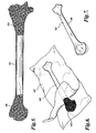
- An artificial bone 20 constructed in accordance with one embodiment of the present disclosure may be best understood by referring to FIGURE 1 .
- the bone 20 includes an outer wall 22 having an inner cavity 24, and an inner core 26 disposed within at least a portion of the inner cavity 24.
- the outer wall 22 and the inner cavity 24 are designed and configured to have characteristics and properties that are similar to mammalian bone when subjected to the procedures designed for fracturing and repairing bones, including bones and bone joints, and when subjected to dynamic biomechanical experimentation.
- the artificial bone 20 is a manufactured alternative to mammalian cadaver bones for use in orthopedic instruction and experimentation. Accordingly, the artificial bone 20 is designed to simulate mammalian bone when broken and subjected to repair, for example, when subjected to cutting, drilling, and/or the injection of bone structure reinforcing compounds, such as bone cement compounds.
- the artificial bone 20 offers an alternative to human bones for examining the effectiveness of cementitious compounds to be used in bone repair procedures or in cement augmentation for osteoporotic bones.
- the artificial bone 20 offers an alternative to human bones for static and dynamic biomechanical experiments. For example, artificial bones can be used to test the life cycle and durability of prostheses, artificial joints, orthopedic hardware and devices, etc. Under the conditions described above, artificial bones are a preferable alternative to cadaver bones because they have reduced inter-specimen variation, do not degrade over time, and are generally lower in cost in comparison to cadaver bones.
- an artificial human humerus bone 20 there is shown an artificial human humerus bone 20; however, it should be understood that all mammalian bones and joints, in addition to the human humerus bone, are within the scope of the present disclosure.
- the properties of the outer wall 22, inner cavity 24, and inner core 26 of the artificial bone 20 are all designed to have characteristics and features similar to mammalian cortical bone, medullar cavity, and cancellous bone, as will now be described in greater detail.
- characteristics and features may include standard morphological properties of mammalian bone, such as volume fraction, surface to volume ratio, trabecular number, trabecular thickness, trabecular spacing or cell size, intercept length, connectivity index, degree of anisotropy, and characterization of the bone.
- characteristics and features may include compressive properties of mammalian bone, such as apparent density, stiffness, measured as apparent modulus of elasticity, and strength, measured as ultimate stress.
- the outer wall 22 is designed and configured to have characteristics and features similar to mammalian cortical bone when subjected to the procedures designed for fracturing and repairing bones and joints and when subjected to biomechanical experimentation.
- the outer wall 22 may be made from a rigid, fracturable and drillable material, such as a rigid polymer material. Suitable materials include, but are not limited to, thermoplastics and thermosets, such as polyurethanes, resins, fiberglass, fiberglass filled resins and epoxies, and other suitable materials.
- the outer wall 22 is reaction injection molded from a liquid polyurethane foam that is transferred to a mold for the outer wall.
- the thickness of the outer wall 22 may also be designed and configured to simulate mammalian bone.
- a thicker outer wall 22 is generally used to simulate healthy mammalian bones, while a thinner outer wall 22 is generally used to simulate osteoporotic mammalian bones.
- the thickness of an artificial osteoporotic bone is generally about 50% to about 80% less than the thickness of an artificial healthy bone.
- the inner cavity 24 is designed and configured to have characteristics and features similar to a mammalian medullar cavity when subjected to the procedures designed for fracturing and repairing bones and when subjected to biomechanical experimentation.
- the inner cavity 24 is shown as an empty cavity.
- the inner cavity may include a spacer or bladder and/or may be filled with suitable materials for ease of manufacturing or for other design or functional factors.
- the inner core 26 is disposed within at least a portion of the inner cavity 24.
- the inner core 26 is also designed and configured to have similar characteristics and features as mammalian cancellous bone (or trabecular bone) when subjected to the procedures designed for fracturing and repairing bones and when subjected to biomechanical experimentation.
- the inner core 26 generally has a porous, open cell structure, including interstices or passages between cells. These interstices are designed to be permeable to high-viscosity fluids, such as air, water, and other fluids.
- the interstices are designed to be penetrated by a bone structure reinforcing compound, such as a bone cement compound, when the compound is injected or otherwise introduced into the region, for example, for the purposes of cement augmentation or setting orthopedic hardware and devices (including, but not limited to, pins, screws, wires, rods, anchors, prostheses, artificial joints, joint repair hardware, and other devices used to repair bones).
- a bone structure reinforcing compound such as a bone cement compound
- the inner core 326 may include a barrier layer 342 to prevent outer wall 322 molding materials from penetrating the porous, open cell structure of the inner core 326 during manufacture, as described in greater detail below.
- the barrier layer 342 may be an plastic film layer that is impermeable to the molding materials of the outer wall 322 used to cover the outer surface of the inner core 326.
- the barrier layer 324 may be a urethane film.
- An inner core 26 formed in accordance with embodiments of the present disclosure has morphological properties that are similar to or within a range of properties for mammalian cancellous bone, such as volume fraction, surface to volume ratio, connectivity index, and characterization, as described in greater detail below in EXAMPLE 1.
- an inner core 26 formed in accordance with embodiments of the present disclosure has stiffness, strength, and density properties that are within the range of properties for mammalian cancellous bone when tested under compression.
- the human cancellous bone data was compiled from the following documents:
- the upper limit for apparent density is defined by the openness of the interstices and passages between cells of the open cell structure required to allow for permeation of a bone structure reinforcing compound, such as a bone cement compound. If the apparent density of the open cell structure becomes too high, the cells are not open enough to allow penetration of a bone cement compound.
- the inner core 26 has an apparent modulus of elasticity of at least about 26 MPa. In another embodiment, the inner core 26 has an apparent modulus of elasticity in a range of about 26 MPa to about 673 MPa. In another embodiment, the inner core 26 has an apparent modulus of elasticity in a range of about 55 MPa to about 535 MPa. In another embodiment, the inner core 26 has an apparent modulus of elasticity in a range of about 26 MPa to about 200 MPa. In yet another embodiment, the inner core 26 has an apparent modulus of elasticity in a range of about 26 MPa to about 100 MPa.
- the inner core 26 has strength, measured as ultimate stress, of at least about 0.32 MPa. In another embodiment, the inner core 26 has ultimate stress in a range of about 0.32 MPa to about 46 MPa. In another embodiment, the inner core 26 has ultimate stress in a range of about 0.34 MPa to about 12.08 MPa. In another embodiment, the inner core 26 has ultimate stress in a range of about 0.32 MPa to about 1.0 MPa. In yet another embodiment, the inner core 26 has ultimate stress in a range of about 0.32 MPa to about 0.60 MPa.
- the inner core 26 has an apparent density of at least about 0.09 g/cm 3 . In another embodiment, the inner core 26 has an apparent density in a range of about 0.09 g/cm 3 to about 0.64 g/cm 3 . In another embodiment, the inner core 26 has an apparent density in a range of about 0.09 g/cm 3 to about 0.49 g/cm 3 . In another embodiment, the inner core 26 has an apparent density in a range of about 0.12 g/cm 3 to about 0.49 g/cm 3 . In yet another embodiment, the inner core 26 has an apparent density in a range of about 0.15 g/cm 3 to about 0.49 g/cm 3 .
- osteoporotic cancellous bone has lower stiffness and/or strength properties when tested under compression compared to healthier, non-osteoporotic bones.
- osteoporotic cancellous bone generally has an apparent modulus of elasticity values of less than about 100 MPa and ultimate stress values of less than about 2 MPa
- healthier, non-osteoporotic cancellous bone generally has an apparent modulus of elasticity values of greater than about 100 MPa and ultimate stress values of greater than about 2 MPa.
- osteoporotic cancellous bone generally has a lower apparent density compared to healthier, non-osteoporotic cancellous bone.
- osteoporotic cancellous bone generally has an apparent density of less than about 0.20 g/cm 3
- healthier, non-osteoporotic cancellous bone generally has an apparent density of greater than about 0.20 g/cm 3 .
- inner cores formed in accordance with the foregoing embodiments may show some crumbling when subjected to fracturing, cutting, drilling, or the insertion of hardware, such as pins and/or screws, similar to the properties of mammalian cancellous bone subjected to the same procedures.
- an inner core 26 that has properties and characteristics corresponding to mammalian cancellous bone, as described above, is a hardened reticulated open cell foam.
- the inner core 26 is a dry, formable, reticulated open cell foam, such as an open cell polyurethane, polyester, or other suitable open cell foam, for example, polyurethane open cell foam having about 14 ppi (pores per inch) and being about 95% open, manufactured by the E.N. MURRAY CO. and sold as product PTA 14 ppi Natural, having a density of about 0.023 g/cm 3 .
- the open cell foam has pores per inch in the range of about 10 to about 45 pores per inch.
- the reticulated open cell foam begins as a formable or pliable foam, but is impregnated with an inner core hardening agent, such as resin, ceramic, or metal, including alloys or oxides thereof, to fabricate suitable strength, stiffness, and density properties for the foam to simulate mammalian cancellous bone, as described in greater detail above.
- an inner core hardening agent such as resin, ceramic, or metal, including alloys or oxides thereof.
- Such impregnation of the foam may be accomplished by dipping, saturating, coating, or injecting the inner core hardening agent, or by any other method of impregnation by a fluid hardening agent.
- the impregnated hardening agent cures within the foam open cell structure, the once-formable foam becomes a hardened foam having strength, stiffness, and density properties in accordance with the present disclosure.
- a suitable amount of hardening agent applied to the open cell foam achieves stiffness, strength, and apparent density properties that are similar to or within a range of properties for mammalian cancellous bone, while also maintaining a suitable open cell structure to allow a bone structure reinforcing compound, such as bone cement, to penetrate through the open cells.
- the formable open cell foam is impregnated with epoxy, urethane, silicon, ceramic, or other suitable hardening resins.
- suitable epoxy resins include, but are not limited to, marine grade epoxy resin, manufactured by TAP®, including resin #314 blended with B-side hardener #109, RENLAM®4017 resin blended with Ren®1510 hardener manufactured by HUNTSMAN TM , and epoxy resin systems manufactured by COTRONICS CORPORATION.
- the resin can be suitably combined with filler materials to increase the strength properties of the hardened open cell foam.
- suitable filler materials include, but are not limited to, glass fiber, such as 3032 milled e-glass fiber, manufactured by FIBERTEC TM , carbon fiber, micro- or nano-sized fillers, and nanocrystalline metals and alloys, such as those manufactured by POWERMETAL TECHNOLOGIES, INC.
- a suitable metal-filled resin is EC-433 High Temp Epoxy Casting System Aluminum Filled and EC-433-2 Hardener, manufactured by ADTECH PLASTIC SYSTEMS.
- the open cell foam may be hardened with castable ceramics, such as those manufactured under the brand name RESCOR TM , including products 750 and 780.
- an open cell foam impregnated with an aluminum-filled epoxy resin with an apparent density of 0.31 g/cm 3 resulted in about 6-fold improvements in apparent modulus and ultimate stress values compared to the same open cell foam impregnated with an aluminum-filled epoxy resin with an apparent density of 0.15 g/cm 3 (see TABLE 2, RD3 and RD4 data).
- the inventors further discovered that such impregnation with an aluminum-filled epoxy resin having an apparent density of 0.31 g/cm 3 still achieves openness in the interstices and passages between cells to allow for permeation of a bone structure reinforcing compound, such as a bone cement compound.
- a method for impregnating and hardening a dry, formable open cell foam with an inner core hardening agent includes the following method steps.
- a liquid hardening agent mixture is prepared, such as a resin, ceramic, or metal, including alloys or oxides thereof.
- the weight of the dry, formable open cell foam is then recorded.
- the dry, formable open cell foam sample is then saturated with the liquid hardening agent. Excess liquid hardening agent is then removed from the wet, saturated, formable foam sample, for example, by being squeezed through a roller system that acts like a squeegee to remove excess hardening agent.
- the weight of wet, saturated, formable open-cell foam sample is then recorded to determine whether a proper amount of saturation has occurred. For example, if the weight of the wet, saturated, formable open-cell foam is too high or low, then the weight can be adjusted by changing the distance between the roller system and repeating the squeegee process until the wet sample of foam is within a specified weight range based on dry density, such that dry density is within the range of density values for mammalian cancellous bone.
- the wet, saturated, formable open cell foam is then dried in a ventilated area until the hardening agent has cured. It should be appreciated that the method steps described herein for impregnating and hardening a dry, formable open cell foam with a hardening agent are exemplary in nature and not intended to be limiting.
- a suitable hardened reticulated open cell foam can be used as the inner core 26 of an artificial bone 20 in accordance with embodiments of the present disclosure.
- a user can drill or cut into the bone 20 using standard orthopedic tools and cutting and drilling devices.
- a bone structure reinforcing compound such as a suitable cementitious compound used for orthopedic repair and augmentation as described above, can be injected into the inner cavity 24 of the bone 20.
- the bone cement permeates the inner cavity 24, and because the inner core 26 is a hardened, porous material having open passages throughout its structure, the bone cement is able to permeate the portion of the inner core 26 adjacent the hole.
- orthopedic hardware such as an orthopedic screw
- the bone cement will harden around the hardware to set the hardware within the cement-reinforced inner core 26.
- the bone cement can be used to augment the cancellous bone structure.
- the manufacture of artificial bones 420 having closed cell artificial cancellous bone generally includes molding, for example, by reaction injection molding, an inner core 426 of artificial cancellous bone using an inner core mold (not shown).
- a suitable spacer 440 shown as a pin, extending longitudinally through the inner core 426, may be used to define an inner cavity 424 ( FIGURE 15 ) in or adjacent the inner core 426.
- the inner core 426 may be reaction injection molded from a low density polyurethane foam material, for example, having a density in the range of about 0.08 to about 0.24 g/cm 3 .
- the inner core 426 and the pin 440 are placed in a second larger mold (not shown), and an outer wall 422 is injection molded around the inner core 426 and the pin 440 (see FIGURE 14 ).
- the outer wall 422 may be molded from a higher density polyurethane material than the inner core 426, for example, having a density in the range of about 0.32 to about 0.48 g/cm 3 .
- a first method of manufacturing artificial bones will be described with reference to FIGURE 2 .
- the method includes forming first and second portions 30 and 32 of the outer wall 22. It should be understood that such first and second portions 30 and 32 may be formed as separate portions or as an integral outer wall 22, which is later cut into first and second portions 30 and 32.
- the outer wall 22, including any separate portions may be formed by reaction injection molding or any other suitable forming method. If formed by reaction injection molding, it should be appreciated that a suitable spacer (not shown) may be inserted in the mold to defme an outer wall 22 having an inner cavity 24 (see FIGURE 1 ) during the molding process.
- first and second outer wall portions 30 and 32 are divided generally along the longitudinal axis of the bone 20. It should be understood, however, that the first and second outer wall portions 30 and 32 need not be divided along the longitudinal axis of the bone 20, but can be divided along any sectional portions that provide access to the inner cavity 24 of the bone 20. It should further be understood that a bone having more than first and second outer wall portions is also within the scope of this disclosure.
- Each of the first and second outer wall portions 30 and 32 define a portion of an inner cavity 24 such that, when the first and second outer wall portions 30 and 32 are assembled into a complete outer wall 22, the outer wall 22 defines an inner cavity 24 (see FIGURE 1 ).
- the method further includes forming an inner core 26 configured to fit within the inner cavity 24 (see FIGURE 1 ), wherein the inner core 26 has hardness and porosity properties that are similar to mammalian bone, as described above.
- the inner core 26 is hardened, for example, by resin impregnation and curing, before being formed to have characteristics and features similar to cortical bone, such that the inner core suitably fits within at least a portion of the inner cavity 24 of the bone 20.
- the hardened inner core 26 can be formed by being machined, cut, ground, thermoformed, molded, or otherwise formed in accordance with any other suitable forming methods.
- the method includes inserting the inner core 26 within a portion of the inner cavity 24 of the first outer wall portion 30 and attaching the second outer wall portion 32 to the first outer wall portion 30 to form the outer wall 22 having an inner core 26 disposed within at least a portion of the inner cavity 24.
- the attachment of the first and second outer wall portions 30 and 32 may be by adhesive, heat sealing, mechanical attachment means, or any other suitable attachment mechanism.
- a mold release formula is applied to release the first and second outer wall portions 30 and 32 from their respective molds. The inventors have found that such mold release formula may need to be removed from the first and second outer wall portions 30 and 32 before using adhesive for attachment.
- a second method of manufacturing artificial bones will be described, also with reference to FIGURE 2 .
- the second method is substantially similar to the first method, except that the inner core 26 is a formable or pliable, porous material, and additional forming and hardening of the inner core 26 takes place after the inner core 26 has been fit or placed within the inner cavity 24 of the bone 20.
- the porous, formable inner core 26 is formed and placed within at least a portion of the inner cavity 24.
- the inner core 26 is subsequently hardened (for example, by resin impregnation and curing) after being placed within the inner cavity 24.
- the inner core 26 is a porous material, as the inner core hardening agent (such as resin) is introduced into the inner cavity 24, the hardening agent readily permeates throughout the inner core 26 within the inner cavity 24. As the hardening agent cures, the inner core 26 is hardened to specific parameters in accordance with the present disclosure.
- the inner core hardening agent such as resin
- the inner core 26 need not be formed to fit exactly within the inner cavity 24 prior to placement in the inner cavity 24, but rather is additionally formed as a result of its conforming to the shape of the inner cavity 24 into which it is placed, then hardened to maintain its form.
- the inner core 26 may be saturated with an inner core hardening agent, such as resin, outside the inner cavity 24, then inserted into the inner cavity 24 before the hardening agent has cured.
- the porous, formable inner core 26 may be placed between the first and second outer wall portions 30 and 32, which are then attached to one another to form an artificial bone 20.
- the inner core 126 may be inserted (or squeezed) into the inner cavity 124 through an opening 134 in the outer wall 122, i.e., instead of dividing the outer wall 122 into one or more portions, as described above.
- the inner core 126 when inserted through an opening 134 in the outer wall 122, the inner core 126 may be saturated with an inner core hardening agent outside the inner cavity 124, then inserted into the inner cavity 124 before the hardening agent has cured, or the inner core hardening agent may be applied to the inner core 126 in the inner cavity 124 through the same opening 134.
- the opening 134 in the outer wall 122 can be patched with suitable patching materials.
- the third method is substantially similar to the first method, except that the outer wall 322 (see FIGURE 9 ) is formed as a substantially continuous outer wall around the inner core 326 (see FIGURE 5 ).
- a suitable substantially continuous outer wall 322 is substantially free of seams, for example, along the longitudinal axis of the bone 20.
- an inner core 326 is designed configured to fit within an inner cavity 324 of an outer wall 322 (see FIGURE 9 ).
- the inner core 326 has hardness and porosity properties that are similar to mammalian bone, as described above.
- the inner core 326 may include a suitable spacer 344 to maintain an empty space for the inner cavity 324.
- the spacer 344 is shown as a hollow cylinder, which may be suitably made from similar materials as the outer wall 322. It should be appreciated, however, that suitable spacers may include air-filled balloons or bladders positioned adjacent the inner core 326.
- the inner core 326 includes a barrier layer 342.
- a barrier layer 342 is formed over the inner core 326 and the spacer 344.
- a suitable barrier layer is a plastic film layer, such as a thin urethane film layer.
- the inner core 326 and spacer 344 are sealed between first and second plies of a suitable barrier layer 342.
- the barrier layer 342 can then be heat pressed or vacuum sealed to the inner core 26 and spacer 344 to form a barrier layer around the inner core 26.
- an optional adhesive may be used on the first and second plies of the barrier layer 342 to promote adhesion between the barrier layer 342 and the inner core 326.
- excess barrier layer material can be cut away from the joining seam 346 between the first and second plies of the barrier layer 342.
- first and second outer wall portions 30 and 32 may be used as spacers to aid in the process of forming the barrier layer 342 around the inner core 326.
- first and second outer wall portions 30 and 32 are placed in a mold, first and second plies of the barrier layer 342 are draped over the outer wall portions 30 and 32, and the inner core 326 is placed in one of the first and second outer wall portions 30 and 32.
- the barrier layer 342 can then be heat pressed or vacuum sealed within first and second outer wall portions 30 and 32 to form a barrier layer around the inner core 26.
- the mold can be reopened, and the first and second outer wall portions 30 and 32 can be removed from the mold.
- a substantially continuous outer wall 322, i.e., an outer wall substantially free of seams, is formed around the inner core 326 and barrier layer 342.
- the outer wall 322 may be configured to cover the joining seam 346 between the first and second plies of the barrier layer 342 to ensure outer wall strength along the barrier layer seam 346.
- the inner core 26 having a barrier layer 342 may be returned to the mold used to form the barrier layer 342.
- the mold can be filled with an outer layer molding material, such as liquid urethane or fiberglass filled epoxy, around the inner core 326 and barrier layer 342.
- the molding material cures around the inner core 26 and forms a substantially continuous outer wall 22 around the inner core 26, i.e., an outer wall substantially free of seams.
- Artificial bones made with a substantially continuous outer wall are significantly advantageous over artificial bones made by securing first and second outer wall portions 30 and 32 to one another, for example, with adhesive applied generally along the longitudinal axis of the bone 20.
- artificial bones having a substantially continuous outer wall have a reduced failure rate, for example, when subjected to drilling or cutting in orthopedic practice and biomechanical testing, as a result of the absence of a seam along the longitudinal axis of the bone.
- this method eliminates the step of removing the mold release formula which tends to prevent strong adhesive attachment between first and second outer wall portions 30 and 32.
- EXAMPLE 1 includes standard morphological data for artificial cancellous bone formed in accordance with embodiments of the present disclosure and similar data for human cancellous bone obtained from human vertebrae.
- EXAMPLE 2 includes static compressive data for samples of artificial cancellous bone formed in accordance with embodiments of the present disclosure and similar data for human cancellous bone.
- EXAMPLE 3 describes results of fatigue tests performed on artificial cancellous bone formed in accordance with embodiments of the present disclosure and similar data for human cancellous bone.
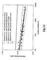
- EXAMPLE 4 describes results from the effective strain tests performed on artificial cancellous bone formed in accordance with embodiments of the present disclosure and similar data for bovine trabecular bone, human vertebral bone, and closed cell foam.
- Standard morphological parameters of exemplary hardened reticulated open cell foam formed in accordance with embodiments of the present disclosure and data for human cancellous bone obtained from human vertebrae are shown below in TABLE 1.
- BV/TV volume fraction
- BS/TV surface to volume ratio
- Tb.N trabecular number
- Tb.Th trabecular thickness
- Tb.Sp trabecular spacing or cell size
- MIL1,2,3 is mean intercept length (in mm)
- TCI connectivity index (in mm -1 )
- DA degree of anisotropy and is equal to the maximum mean intercept length (i.e., one of MIL1, MIL2, and MIL3) divided by the minimum mean intercept length (i.e., one of MIL1, MIL2, and MIL3)
- a morphology characterization of "TI” is
- samples #1521-55 and #1521-59 were both prepared using the same process, including the following method steps: (1) preparing an epoxy mixture (specific mixture described below); (2) recording the weight of the dry formable open cell foam having 14 ppi (pores per inch), manufactured by the EN MURRAY COMPANY, and sold as product PTA 14 ppi Natural having a density of 0.023 g/cm 3 ; (3) soaking the formable open cell foam sample with the epoxy mixture; (4) feeding the saturated foam sample through two aluminum rollers that act like a squeegee to remove excess epoxy; (5) recording the weight of wet formable open-cell foam sample; (6) if the weight of the wet formable open-cell foam was too high or low, then adjusting the distance between the rollers and repeating the squeegee process until the sample of foam is within a specified weight range, based on dry density; and (7) hanging the open cell foam samples in a ventilated area until the wet foam has cured.
- an epoxy mixture specifically mixture described below
- Sample #1521-55 includes marine grade epoxy resin, manufactured by TAP@, including resin #314 blended with B-side hardener #109.
- Sample #1521-59 includes marine grade epoxy resin, manufactured by TAP®, including resin #314 blended with B-side hardener #109, combined with 3032 milled e-glass fiber, manufactured by FIBERTECTM, in a 1:1 ratio with the resin portion of the epoxy system.
- results shown above in TABLE 1 are based on micro computed tomography (micro-CT) data of hardened reticulated open cell foam samples #1521-55 and #1521-59.
- the data shows that the hardened reticulated open cell foam formed in accordance with embodiments of the present disclosure has some similar morphology properties to the data collected for human vertebral cancellous bone.
- volume fraction (BV/TV), surface to volume ratio (BS/TV), and connectivity index (TCI) values for samples #1521-55 and #1521-59 are all within the ranges for the human vertebral cancellous bone Data 2.
- volume fraction (BV/TV) values for samples #1521-55 and #1521-59 are both within the range for the human cancellous bone Data 3
- volume fraction (BV/TV) values for sample #1521-59 are within the ranges for human vertebral cancellous bone Data 1 and Data 2.
- the appearance of the rigid open-cell foam samples #1521-55 and #5121-59 and human cancellous bone are similar.
- the characterization of the bone as transverse isotropic (TI) is the same in samples #1521-55 and #1521-59 and that of the vertebral bone data provided in Data 1 and Data 2.
- both artificial and human bone have interconnected networks of rods or trabeculae, as best seen in FIGURES 10A-10C .
- the structure of the rigid open cell foam comprises an integrated network of thin, interconnected artificial bone trabeculae.
- the artificial trabeculae when compared to the trabeculae in human cancellous bone (see FIGURES 10B and 10C ), the artificial trabeculae have thicker and more widely spaced elements.
- trabecular number (Tb.N) for the samples is generally lower than that of the human cancellous bone data provided; trabecular thickness (Tb.Th) is generally higher than that of the human cancellous bone data provided; trabecular spacing or cell size (Tb.Sp), mentioned above, is generally higher than that of the human cancellous bone data provided; and intercept length (MIL1,2,3) is generally higher than that of the human cancellous bone data provided.
- Tb.N trabecular number
- Tb.Th trabecular thickness
- Tb.Sp trabecular spacing or cell size
- intercept length (MIL1,2,3) is generally higher than that of the human cancellous bone data provided.
- the ratio of trabecular thickness (Tb.Th) to trabecular spacing or cell size (Tb.Sp) for sample #1521-59 is within the range for human vertebral cancellous bone Data 2 and human cancellous bone Data 3.
- This correlation is likely a result of the larger trabeculae cell size for artificial cancellous bone compared to that of human cancellous bone, as best seen in FIGURES 10A-10C , and the increased thickness of the artificial cancellous bone trabeculae compared to that of human cancellous bone, as a result of the resin coating.
- the degree of anisotropy for the #1521-55 and #1521-59 samples are within the range of anisotropy for human vertebral cancellous bone Data 2.
- the degree of anisotropy is directed to the shape of the pores, with a value of 1.0 being perfectly round.
- the correlation between the artificial cancellous bone samples and human cancellous bone data indicates that both artificial and human cancellous bone have generally rounded pores.
- Samples RD1, RD2, RD3, and RD4 were prepared using similar processes, including the following method steps: (1) preparing an epoxy mixture (specific mixture described below); (2) recording the weight of the dry formable open cell foam having 14 ppi (pores per inch), manufactured by the EN MURRAY COMPANY, and sold as product PTA 14 ppi Natural having a density of 0.023 g/cm 3 ; (3) soaking the formable open cell foam sample with the epoxy mixture; (4) feeding the saturated foam sample through two aluminum rollers that act like a squeegee to remove excess epoxy; (5) recording the weight of wet formable open-cell foam sample; (6) if the weight of the wet formable open-cell foam was too high or low, then adjusting the distance between the rollers and repeating the squeegee process until the sample of foam is within a specified weight range, based on dry density; and (7) hanging the open cell
- Sample RD1 uses a resin system sold under the brand names RENLAM®4017 resin and Ren®1510 hardener as a heat resistant laminating system, manufactured by HUNTSMANTM.
- the application of RD1 resin to the dry formable open cell foam results in a hardened open cell foam having an apparent density of about 0.11 g/cm 3 .
- Sample RD2 uses a resin system sold under the brand names RENLAM®4017 resin and Ren®1510 hardener as a heat resistant laminating system, manufactured by HUNTSMANTM, combined with 3032 milled e-glass fiber, manufactured by FIBERTECTM, in a 1:1 ratio with the resin portion of the system.
- RD2 resin to the dry formable open cell foam results in a hardened open cell foam having an apparent density of about 0.18 g/cm 3 .
- Samples RD3 and RD4 used a resin system sold as EC-433 High Temp Epoxy Casting System Aluminum Filled and EC-433-2 Hardener, manufactured by ADTECH PLASTIC SYSTEMS.
- the application of RD3 resin to the dry formable open cell foam results in a hardened open cell foam having an apparent density of about 0.31 g/cm 3
- the application of RD4 resin to the dry formable open cell foam results in a hardened open cell foam having an apparent density of about 0.15 g/cm 3 .
- the compressive properties for human cancellous bone were compiled from mean data for 1133 compressive test samples performed on either cylindrical cores or cube specimens of human cancellous bone taken from vertebrae, femurs, and tibias from cadaver bone aged 20-100 years, using a method with uniaxial compressive loading at various strain rates.
- Large variations in the mechanical properties of human cancellous bone may be a result of differences in subject age, degeneration, bone density, and source of bone (e.g., vertebral, tibial, etc.).
- cylindrical cores 15 mm diameter by 30 mm height were loaded to failure under displacement control (1% strain/second) using an INSTRON® 4204 load frame with a 50 kN load cell.
- the dimensions of each specimen were measured with digital calipers and averaged over three measurements.
- Specimens were potted with end caps of 2mm polyester resin manufactured by DYNATRON®/BONDO CORP. to reinforce the load-bearing surfaces.
- Specimens were conditioned at 77°F for 4 hours prior to testing. A preload of 0.02 MPa was applied to each specimen to initiate contact with the surface and zero the displacement measurement. Load versus displacement data was collected using an INSTRON® chart recorder.
- the compression properties for the rigid open-cell foam samples listed in TABLE 2 above can be compared to the mean minimum and maximum compression properties for human cancellous bone.
- the apparent density for all of the rigid open-cell foam samples fall within the minimum and maximum apparent density ranges for human cancellous bone, 0.09 to 0.64 g/cm 3 .
- the apparent modulus for the RD1, RD2, RD3, and RD4 rigid open-cell foam samples fall within the minimum and maximum apparent modulus ranges for human cancellous bone, 26 to 673 MPa.
- only the ultimate stress for RD1, RD2, RD3, and RD4 rigid open-cell foam samples fall within the minimum and maximum ultimate stress properties for human cancellous bone, 0.32 to 46 MPa.
- results from the fatigue tests performed on artificial cancellous bone sample #1521-59 are plotted in FIGURE 11 , as compared to a curve-fit of degradation data for human cancellous bone.
- This data shows that artificial cancellous bone sample #1521-59, when subjected to dynamic strength tests, has similar general behavior (non-linear modulus degradation) for normalized apparent modulus of elasticity per life fraction when compared to human cancellous bone data, as published in Pattin, C.A., Caler, W.E. Carter, D.R., "Cyclic Mechanical Property Degradation During Fatigue Loading of Cortical Bone," J. Biomechanics 29:69-79, 1996 .
- Results from the effective strain tests performed on artificial cancellous bone samples #1521-59 and #1521-55 are plotted in FIGURE 12 and compared to effective strain tests performed on bovine trabecular bone, human vertebral bone, and closed cell foam, showing similar S-N curve behavior. Samples #1521-59 and #1521-55 fall within the same effective strain range as human cancellous bone. Closed cell foam shows a different effective strain range than human cancellous bone.
Landscapes
- Health & Medical Sciences (AREA)
- Chemical & Material Sciences (AREA)
- Engineering & Computer Science (AREA)
- General Health & Medical Sciences (AREA)
- Animal Behavior & Ethology (AREA)
- Oral & Maxillofacial Surgery (AREA)
- Medicinal Chemistry (AREA)
- Transplantation (AREA)
- Veterinary Medicine (AREA)
- Life Sciences & Earth Sciences (AREA)
- Public Health (AREA)
- Physics & Mathematics (AREA)
- General Physics & Mathematics (AREA)
- Dermatology (AREA)
- Epidemiology (AREA)
- Educational Technology (AREA)
- Vascular Medicine (AREA)
- Theoretical Computer Science (AREA)
- Orthopedic Medicine & Surgery (AREA)
- Cardiology (AREA)
- Business, Economics & Management (AREA)
- Pure & Applied Mathematics (AREA)
- Biomedical Technology (AREA)
- Heart & Thoracic Surgery (AREA)
- Educational Administration (AREA)
- Mathematical Physics (AREA)
- Mathematical Optimization (AREA)
- Mathematical Analysis (AREA)
- Computational Mathematics (AREA)
- Algebra (AREA)
- Medical Informatics (AREA)
- Dispersion Chemistry (AREA)
- Prostheses (AREA)
- Materials For Medical Uses (AREA)
Claims (15)
- Ein künstlicher Knochen (20, 120) bestehend aus:(a) einer Außenwand (22, 122, 322), die einen inneren Hohlraum (24, 124, 324) definiert; und(b) einem inneren Kern (826, 126, 326), der in zumindest einem Teil des inneren Hohlraums (24, 124) positioniert ist, wobei der innere Kern (26, 126, 326) ein poröses Material umfasst, dass eine Steifigkeit mit einer Reihe von Steifigkeitseigenschaften für Säugetierspongiosa und eine Stärke innerhalb eines Bereiche von Stärkeeigenschaften für Säugetierspongiosa aufweist, wobei der innere Kern (26, 126, 326) eine Trennschicht (342) umfasst, um die Außenwand vom porösen Material zu trennen.
- Der künstliche Knochen entsprechend Anspruch 1, wobei der innere Kern (26, 126, 326) ein poröses Material umfasst, das einen offensichtlichen Elastizitätsmodul von mindestens ca. 26 MPa und eine Zugfestigkeit von mindestens ca. 0,32 MPa aufweist.
- Der künstliche Knochen entsprechend Anspruch 1 oder 2, wobei die Außenwand (22) wesentlich ununterbrochen ist.
- Der künstliche Knochen entsprechend einem der Ansprüche 1 bis 3, wobei der innere Kern (26, 126, 326) einen Steifigkeit aufweist, die als offensichtlicher Elastizitätsmodul innerhalb eines Bereichs gemessen wird, der aus den Bereichen bestehend aus ca. 26 MPa, ca. 26 MPa bis ca. 673 MPa, ca. 55 MPa bis ca. 535 MPa, ca. 26 MPa bis ca. 200 MPa und ca. 26 MPa bis ca. 100 MPa ausgewählt wird.
- Der künstliche Knochen entsprechend einem der Ansprüche 1 bis 4, wobei der innere Kern (26, 126, 326) eine offensichtliche Dichte innerhalb eines Bereichs aufweist, der aus den Bereichen bestehend aus mindestens 0,9 g/cm3, ca. 0,09 bis ca. 0,64 g/cm3, ca. 0,09 bis ca. 0,49 g/cm3, ca. 0,12 bis ca. 0,49 g/cm3 und ca. 0,15 bis 0,49 g/cm3 ausgewählt wird.
- Der künstliche Knochen entsprechend einem der Ansprüche 1 bis 5, wobei der innere Kern (26, 126, 326) eine Stärke aufweist, die durch die Zugfestigkeit innerhalb eines Bereichs gemessen wird, der aus den Bereichen bestehend aus mindestens 0,32 MPa, ca. 0,32 MPa bis ca. 46 MPa, ca. 0,34 MPa bis ca. 12,08 MPa, ca. 0,34 MPa bis ca. 1, MPa und ca. 0,34 MPa bis 0,60 MPa ausgewählt wird.
- Der künstliche Knochen entsprechend einem der Ansprüche 1 bis 6, wobei der innere Kern (26, 126, 326) ein offenzelliger Schaum mit ca. 10 bis ca. 40 Poren pro Zoll ist.
- Der künstliche Knochen oder das Verfahren entsprechend Anspruch 7, wobei der innere Kern (26, 126, 326) ein offenzelliger Schaum mit ca. 10 bis ca. 20 Poren pro Zoll ist, optional wobei der innere Kern (26, 126, 326) einen starren offenzelligen Schaum umfasst, der optional Folgendes umfasst:(a) einen offenzelligen Schaum, der mit einem Härtemittel gesättigt ist, das aus der Gruppe bestehend aus Harz, Keramik, Metall und einer Kombination dieser ausgewählt wird; und(b) wobei die Außenwand (22, 122, 322) ein Material mit einbezieht, das aus der Gruppe bestehend aus Polyurethan und glasfaserverstärktem Epoxyharz ausgewählt wird.
- Der künstliche Knochen entsprechend einem der Ansprüche 1 bis 8, wobei die Trennschicht (342) eine Kunststofffolie ist.
- Ein Verfahren zur Herstellung eines künstlichen Knochens, bestehend aus:(a) Erhalten eines inneren Kerns (26, 126, 326), wobei der innere Kern (26, 126, 326) ein poröses Material umfasst, dass eine Steifigkeit mit einer Reihe von Steifigkeitseigenschaften für Säugetierspongiosa und eine Stärke innerhalb eines Bereiche von Stärkeeigenschaften für Säugetierspongiosa aufweist;(b) wesentliches Bedecken des innere Kerns (26, 126, 326) mit einer Trennschicht; und(c) Formen einer wesentlich ununterbrochenen Außenwand (22, 122, 322) um den inneren Kern.
- Das Verfahren entsprechend Anspruch 10, wobei der innere Kern (26, 126, 326) eine offensichtliche Dichte innerhalb eines Bereichs aufweist, der aus den Bereichen bestehend aus mindestens 0,9 g/cm3, ca. 0,09 bis ca. 0,64 g/cm3, ca. 0,09 bis ca. 0,49 g/cm3, ca. 0,12 bis ca. 0,49 g/cm3 und ca. 0,15 bis 0,49 g/cm3 ausgewählt wird.
- Das Verfahren entsprechend Anspruch 10, wobei der innere Kern (26, 126, 326) eine Stärke aufweist, die durch die Zugfestigkeit innerhalb eines Bereichs gemessen wird, der aus den Bereichen bestehend aus mindestens 0,32 MPa, ca. 0,32 MPa bis ca. 46 MPa, ca. 0,34 MPa bis ca. 12,08 MPa, ca. 0,34 MPa bis ca. 1, MPa und ca. 0,34 MPa bis 0,60 MPa ausgewählt wird.
- Das Verfahren entsprechend Anspruch 10, wobei der innere Kern (26, 126, 326) ein offenzelliger Schaum mit ca. 10 bis ca. 40 Poren pro Zoll ist, optional wobei der innere Kern (26, 126, 326) ein offenzelliger Schaum mit ca. 10 bis ca. 20 Poren pro Zoll ist.
- Das Verfahren entsprechend Anspruch 13, wobei der innere Kern (26, 126, 326) ein starrer offenzelliger Schaum ist, wobei: mit ca. 10 bis ca. 20 Poren pro Zoll ist, optional wobei der innere Kern (26, 126, 326) einen starren offenzelligen Schaum umfasst, der optional folgendes umfasst:(a) der starre offenzellige Schaum ein offenzelliger Schaum ist, der mit einem Härtemittel gesättigt ist, das aus der Gruppe bestehend aus Harz, Keramik, Metall und einer Kombination dieser ausgewählt wird; und(b) die Außenwand ein Material mit einbezieht, das aus der Gruppe bestehend aus Polyurethan und glasfaserverstärktem Epoxyharz ausgewählt wird.
- Das Verfahren entsprechend Anspruch 14, wobei die Trennschicht (342) eine Kunststofffolie ist.
Applications Claiming Priority (1)
| Application Number | Priority Date | Filing Date | Title |
|---|---|---|---|
| US12/101,853 US8210852B2 (en) | 2007-04-11 | 2008-04-11 | Artificial bones and methods of making same |
Publications (3)
| Publication Number | Publication Date |
|---|---|
| EP2108336A2 EP2108336A2 (de) | 2009-10-14 |
| EP2108336A3 EP2108336A3 (de) | 2013-04-03 |
| EP2108336B1 true EP2108336B1 (de) | 2015-01-28 |
Family
ID=40875215
Family Applications (1)
| Application Number | Title | Priority Date | Filing Date |
|---|---|---|---|
| EP09251061.9A Not-in-force EP2108336B1 (de) | 2008-04-11 | 2009-04-08 | Kunstknochen und Verfahren zu ihrer Herstellung |
Country Status (2)
| Country | Link |
|---|---|
| US (2) | US8210852B2 (de) |
| EP (1) | EP2108336B1 (de) |
Families Citing this family (24)
| Publication number | Priority date | Publication date | Assignee | Title |
|---|---|---|---|---|
| US7947081B2 (en) * | 2007-07-11 | 2011-05-24 | Linares Medical Devices, Llc | Skeletal implant for replacing a human bone |
| US8663326B2 (en) * | 2007-12-13 | 2014-03-04 | Said G. Osman | Biologic artificial bone |
| WO2013052361A1 (en) * | 2011-10-03 | 2013-04-11 | The Cleveland Clinic Foundation | Synthetic bone model and method for providing same |
| US20130137071A1 (en) * | 2011-11-27 | 2013-05-30 | Paul Jordan Washburn | Washburn Orthopedic Module (WOM) |
| KR20150015532A (ko) * | 2012-05-30 | 2015-02-10 | 뉴욕 유니버시티 | 조직 수복 장치 및 스캐폴드 |
| US9142146B2 (en) * | 2012-06-04 | 2015-09-22 | The Johns Hopkins University | Cranial bone surrogate and methods of manufacture thereof |
| DE102012013926A1 (de) * | 2012-07-16 | 2014-01-16 | Albrecht Franke | Anatomiemodell und Verfahren zur Herstellung eines solchen |
| US10650705B2 (en) | 2012-09-11 | 2020-05-12 | Mckenzie Sports Products, Llc | Jointed leg system for taxidermy |
| US9744050B1 (en) | 2013-12-06 | 2017-08-29 | Stryker European Holdings I, Llc | Compression and distraction system for percutaneous posterior spinal fusion |
| US9408716B1 (en) | 2013-12-06 | 2016-08-09 | Stryker European Holdings I, Llc | Percutaneous posterior spinal fusion implant construction and method |
| US10159579B1 (en) | 2013-12-06 | 2018-12-25 | Stryker European Holdings I, Llc | Tubular instruments for percutaneous posterior spinal fusion systems and methods |
| US9622795B2 (en) | 2013-12-13 | 2017-04-18 | Stryker European Holdings I, Llc | Tissue retraction and vertebral displacement devices, systems, and methods for posterior spinal fusion |
| CA2882468A1 (en) | 2014-02-19 | 2015-08-19 | Samin Eftekhari | Artificial bone nanocomposite and method of manufacture |
| WO2016115625A1 (en) * | 2015-01-19 | 2016-07-28 | Ammolite Biomodels Inc. | Simulated bone materials and methods of making same |
| AU2016408342B2 (en) * | 2016-05-23 | 2021-07-29 | Em Resources Llc | Filled polyurethane foam having tailored microstructures |
| CN106983583A (zh) * | 2017-04-27 | 2017-07-28 | 北京爱康宜诚医疗器材有限公司 | 骨骼假体 |
| DE202017105601U1 (de) * | 2017-09-15 | 2018-12-19 | Crashtest-Service.Com Gmbh | Dummy für die Unfallforschung und Forensik |
| WO2019052608A1 (de) * | 2017-09-15 | 2019-03-21 | Crashtest-Service.Com Gmbh | Dummy für die unfallforschung und forensik |
| DE102017121482B4 (de) * | 2017-09-15 | 2023-02-23 | Crashtest-Service.Com Gmbh | Dummy für die Unfallforschung und Forensik |
| FR3095887B1 (fr) * | 2019-05-10 | 2022-06-24 | Addidream | Procede de fabrication assistee par ordinateur d’une maquette sur-mesure d’un os |
| CA3162230A1 (en) | 2019-12-20 | 2021-06-24 | William E. CLIFTON III | Systems and methods for surgical training model |
| CA3180098A1 (en) * | 2020-05-29 | 2021-12-02 | Gwendolyn Mary-jean MORGAN | Tactile synthetic bones |
| JP2024537208A (ja) | 2021-10-07 | 2024-10-10 | アースレックス インコーポレイテッド | 外科手術システム、解剖モデル、および関連する方法 |
| EP4643821A4 (de) * | 2024-03-14 | 2025-12-17 | Nsilica Simulation Tech S L | Rippenprothese mit kontrollierter ealstizität |
Family Cites Families (13)
| Publication number | Priority date | Publication date | Assignee | Title |
|---|---|---|---|---|
| CH601877A5 (de) * | 1975-12-05 | 1978-07-14 | Synthes Ag | |
| US4629464A (en) * | 1984-09-25 | 1986-12-16 | Tdk Corporation | Porous hydroxyapatite material for artificial bone substitute |
| DE29613274U1 (de) * | 1996-07-31 | 1996-10-10 | Bohne, Thomas, 37073 Göttingen | Phantom |
| US6116911A (en) * | 1997-03-27 | 2000-09-12 | The Johns Hopkins University | Bone substitute for training and testing |
| US6977095B1 (en) * | 1997-10-01 | 2005-12-20 | Wright Medical Technology Inc. | Process for producing rigid reticulated articles |
| JP4403268B2 (ja) * | 2001-10-21 | 2010-01-27 | 独立行政法人産業技術総合研究所 | リン酸カルシウム多孔質焼結体の製造方法及びそれを用いた人工骨の製造方法 |
| JP3739715B2 (ja) * | 2002-03-19 | 2006-01-25 | オリンパス株式会社 | 人工骨および組織工学用担体 |
| US7018212B2 (en) * | 2002-09-21 | 2006-03-28 | Medical Accessories & Research Corporation | Artificial bone |
| JP3927487B2 (ja) * | 2002-12-02 | 2007-06-06 | 株式会社大野興業 | 人工骨モデルの製造方法 |
| WO2005011536A1 (ja) * | 2003-07-31 | 2005-02-10 | Riken | 粉末積層法による人工骨成形方法 |
| WO2005020846A2 (en) * | 2003-08-25 | 2005-03-10 | Mcgowan Kenneth A | Artificial bone and joint compositions and methods of use and manufacture |
| US7699615B2 (en) * | 2005-02-03 | 2010-04-20 | Christopher Sakezles | Joint replica models and methods of using same for testing medical devices |
| US20080133026A1 (en) * | 2006-10-20 | 2008-06-05 | Sio-Hou Lei | Artificial bone and a method for making the same |
-
2008
- 2008-04-11 US US12/101,853 patent/US8210852B2/en active Active
-
2009
- 2009-04-08 EP EP09251061.9A patent/EP2108336B1/de not_active Not-in-force
-
2012
- 2012-06-27 US US13/535,275 patent/US8568148B2/en active Active
Also Published As
| Publication number | Publication date |
|---|---|
| EP2108336A3 (de) | 2013-04-03 |
| US8210852B2 (en) | 2012-07-03 |
| US8568148B2 (en) | 2013-10-29 |
| US20120265321A1 (en) | 2012-10-18 |
| US20090216327A1 (en) | 2009-08-27 |
| EP2108336A2 (de) | 2009-10-14 |
Similar Documents
| Publication | Publication Date | Title |
|---|---|---|
| EP2108336B1 (de) | Kunstknochen und Verfahren zu ihrer Herstellung | |
| Charriere et al. | Hydroxyapatite cement scaffolds with controlled macroporosity: fabrication protocol and mechanical properties | |
| CA1321681C (en) | Functional and biocompatible intervertebral disc spacer | |
| US6602293B1 (en) | Polymeric composite orthopedic implant | |
| Parsons et al. | Phosphate glass fibre composites for bone repair | |
| Al-Munajjed et al. | Influence of pore size on tensile strength, permeability and porosity of hyaluronan-collagen scaffolds | |
| Miller et al. | Deformation and fatigue of tough 3D printed elastomer scaffolds processed by fused deposition modeling and continuous liquid interface production | |
| Gloria et al. | Technical features and criteria in designing fiber-reinforced composite materials: from the aerospace and aeronautical field to biomedical applications | |
| Hsu et al. | Fabrication of porous bioceramics with porosity gradients similar to the bimodal structure of cortical and cancellous bone | |
| Hellmich et al. | Drained and undrained poroelastic properties of healthy and pathological bone: a poro-micromechanical investigation | |
| Lin-Gibson et al. | Systematic investigation of porogen size and content on scaffold morphometric parameters and properties | |
| Fu et al. | Strength, toughness, and reliability of a porous glass/biopolymer composite scaffold | |
| Flahiff et al. | Pullout strength of fixation screws from polymethylmethacrylate bone cement | |
| Lennon et al. | The relationship between cement fatigue damage and implant surface finish in proximal femoral prostheses | |
| WO2000000237A1 (en) | Thermoplastic syntactic foam as synthetic bone | |
| Xie et al. | Strengthening mechanism of TPMS interpenetrating phase composites for bone tissue engineering | |
| Yuk et al. | Additive-manufactured synthetic bone model with biomimicking tunable mechanical properties for evaluation of medical implants | |
| van de Vijfeijken et al. | Properties of an in vivo fractured poly (methyl methacrylate) cranioplasty after 15 years | |
| Miller | Fatigue and cyclic loading of 3D printed soft polymers for orthopedic applications | |
| Hingston et al. | Effect of curing characteristics on residual stress generation in polymethyl methacrylate bone cements | |
| US20110201704A1 (en) | Polymeric bone defect filler | |
| Li et al. | Comparison of porous Ti6Al4V made by sponge replication and directly 3D fiber deposition and cancellous bone | |
| EP1962919A1 (de) | Beschichtete textilien | |
| Carroll et al. | Evaluation of a synthetic bone defect test model to aid in the selection of materials for use in vertebral body compression fracture repair | |
| Yoon et al. | Mechanical aspects of degree of cement bonding and implant wedge effect |
Legal Events
| Date | Code | Title | Description |
|---|---|---|---|
| PUAI | Public reference made under article 153(3) epc to a published international application that has entered the european phase |
Free format text: ORIGINAL CODE: 0009012 |
|
| AK | Designated contracting states |
Kind code of ref document: A2 Designated state(s): AT BE BG CH CY CZ DE DK EE ES FI FR GB GR HR HU IE IS IT LI LT LU LV MC MK MT NL NO PL PT RO SE SI SK TR |
|
| PUAL | Search report despatched |
Free format text: ORIGINAL CODE: 0009013 |
|
| AK | Designated contracting states |
Kind code of ref document: A3 Designated state(s): AT BE BG CH CY CZ DE DK EE ES FI FR GB GR HR HU IE IS IT LI LT LU LV MC MK MT NL NO PL PT RO SE SI SK TR |
|
| AX | Request for extension of the european patent |
Extension state: AL BA RS |
|
| RIC1 | Information provided on ipc code assigned before grant |
Ipc: G09B 23/30 20060101ALI20130225BHEP Ipc: A61F 2/28 20060101AFI20130225BHEP |
|
| 17P | Request for examination filed |
Effective date: 20131003 |
|
| RBV | Designated contracting states (corrected) |
Designated state(s): AT BE BG CH CY CZ DE DK EE ES FI FR GB GR HR HU IE IS IT LI LT LU LV MC MK MT NL NO PL PT RO SE SI SK TR |
|
| RIC1 | Information provided on ipc code assigned before grant |
Ipc: G09B 23/30 20060101ALI20131211BHEP Ipc: A61F 2/28 20060101AFI20131211BHEP |
|
| 17Q | First examination report despatched |
Effective date: 20140130 |
|
| GRAP | Despatch of communication of intention to grant a patent |
Free format text: ORIGINAL CODE: EPIDOSNIGR1 |
|
| INTG | Intention to grant announced |
Effective date: 20140925 |
|
| GRAS | Grant fee paid |
Free format text: ORIGINAL CODE: EPIDOSNIGR3 |
|
| GRAA | (expected) grant |
Free format text: ORIGINAL CODE: 0009210 |
|
| AK | Designated contracting states |
Kind code of ref document: B1 Designated state(s): AT BE BG CH CY CZ DE DK EE ES FI FR GB GR HR HU IE IS IT LI LT LU LV MC MK MT NL NO PL PT RO SE SI SK TR |
|
| REG | Reference to a national code |
Ref country code: GB Ref legal event code: FG4D |
|
| REG | Reference to a national code |
Ref country code: CH Ref legal event code: EP |
|
| REG | Reference to a national code |
Ref country code: IE Ref legal event code: FG4D |
|
| REG | Reference to a national code |
Ref country code: DE Ref legal event code: R096 Ref document number: 602009029211 Country of ref document: DE Effective date: 20150312 |
|
| REG | Reference to a national code |
Ref country code: AT Ref legal event code: REF Ref document number: 707902 Country of ref document: AT Kind code of ref document: T Effective date: 20150315 |
|
| REG | Reference to a national code |
Ref country code: CH Ref legal event code: NV Representative=s name: BOVARD AG, CH |
|
| REG | Reference to a national code |
Ref country code: NL Ref legal event code: T3 |
|
| REG | Reference to a national code |
Ref country code: AT Ref legal event code: MK05 Ref document number: 707902 Country of ref document: AT Kind code of ref document: T Effective date: 20150128 |
|
| REG | Reference to a national code |
Ref country code: LT Ref legal event code: MG4D |
|
| PG25 | Lapsed in a contracting state [announced via postgrant information from national office to epo] |
Ref country code: HR Free format text: LAPSE BECAUSE OF FAILURE TO SUBMIT A TRANSLATION OF THE DESCRIPTION OR TO PAY THE FEE WITHIN THE PRESCRIBED TIME-LIMIT Effective date: 20150128 Ref country code: BG Free format text: LAPSE BECAUSE OF FAILURE TO SUBMIT A TRANSLATION OF THE DESCRIPTION OR TO PAY THE FEE WITHIN THE PRESCRIBED TIME-LIMIT Effective date: 20150428 Ref country code: SE Free format text: LAPSE BECAUSE OF FAILURE TO SUBMIT A TRANSLATION OF THE DESCRIPTION OR TO PAY THE FEE WITHIN THE PRESCRIBED TIME-LIMIT Effective date: 20150128 Ref country code: NO Free format text: LAPSE BECAUSE OF FAILURE TO SUBMIT A TRANSLATION OF THE DESCRIPTION OR TO PAY THE FEE WITHIN THE PRESCRIBED TIME-LIMIT Effective date: 20150428 Ref country code: LT Free format text: LAPSE BECAUSE OF FAILURE TO SUBMIT A TRANSLATION OF THE DESCRIPTION OR TO PAY THE FEE WITHIN THE PRESCRIBED TIME-LIMIT Effective date: 20150128 Ref country code: ES Free format text: LAPSE BECAUSE OF FAILURE TO SUBMIT A TRANSLATION OF THE DESCRIPTION OR TO PAY THE FEE WITHIN THE PRESCRIBED TIME-LIMIT Effective date: 20150128 Ref country code: FI Free format text: LAPSE BECAUSE OF FAILURE TO SUBMIT A TRANSLATION OF THE DESCRIPTION OR TO PAY THE FEE WITHIN THE PRESCRIBED TIME-LIMIT Effective date: 20150128 |
|
| PG25 | Lapsed in a contracting state [announced via postgrant information from national office to epo] |
Ref country code: GR Free format text: LAPSE BECAUSE OF FAILURE TO SUBMIT A TRANSLATION OF THE DESCRIPTION OR TO PAY THE FEE WITHIN THE PRESCRIBED TIME-LIMIT Effective date: 20150429 Ref country code: PL Free format text: LAPSE BECAUSE OF FAILURE TO SUBMIT A TRANSLATION OF THE DESCRIPTION OR TO PAY THE FEE WITHIN THE PRESCRIBED TIME-LIMIT Effective date: 20150128 Ref country code: AT Free format text: LAPSE BECAUSE OF FAILURE TO SUBMIT A TRANSLATION OF THE DESCRIPTION OR TO PAY THE FEE WITHIN THE PRESCRIBED TIME-LIMIT Effective date: 20150128 Ref country code: LV Free format text: LAPSE BECAUSE OF FAILURE TO SUBMIT A TRANSLATION OF THE DESCRIPTION OR TO PAY THE FEE WITHIN THE PRESCRIBED TIME-LIMIT Effective date: 20150128 Ref country code: IS Free format text: LAPSE BECAUSE OF FAILURE TO SUBMIT A TRANSLATION OF THE DESCRIPTION OR TO PAY THE FEE WITHIN THE PRESCRIBED TIME-LIMIT Effective date: 20150528 |
|
| REG | Reference to a national code |
Ref country code: DE Ref legal event code: R097 Ref document number: 602009029211 Country of ref document: DE |
|
| PG25 | Lapsed in a contracting state [announced via postgrant information from national office to epo] |
Ref country code: SK Free format text: LAPSE BECAUSE OF FAILURE TO SUBMIT A TRANSLATION OF THE DESCRIPTION OR TO PAY THE FEE WITHIN THE PRESCRIBED TIME-LIMIT Effective date: 20150128 Ref country code: RO Free format text: LAPSE BECAUSE OF FAILURE TO SUBMIT A TRANSLATION OF THE DESCRIPTION OR TO PAY THE FEE WITHIN THE PRESCRIBED TIME-LIMIT Effective date: 20150128 Ref country code: CZ Free format text: LAPSE BECAUSE OF FAILURE TO SUBMIT A TRANSLATION OF THE DESCRIPTION OR TO PAY THE FEE WITHIN THE PRESCRIBED TIME-LIMIT Effective date: 20150128 Ref country code: DK Free format text: LAPSE BECAUSE OF FAILURE TO SUBMIT A TRANSLATION OF THE DESCRIPTION OR TO PAY THE FEE WITHIN THE PRESCRIBED TIME-LIMIT Effective date: 20150128 Ref country code: EE Free format text: LAPSE BECAUSE OF FAILURE TO SUBMIT A TRANSLATION OF THE DESCRIPTION OR TO PAY THE FEE WITHIN THE PRESCRIBED TIME-LIMIT Effective date: 20150128 |
|
| PG25 | Lapsed in a contracting state [announced via postgrant information from national office to epo] |
Ref country code: MC Free format text: LAPSE BECAUSE OF FAILURE TO SUBMIT A TRANSLATION OF THE DESCRIPTION OR TO PAY THE FEE WITHIN THE PRESCRIBED TIME-LIMIT Effective date: 20150128 Ref country code: LU Free format text: LAPSE BECAUSE OF FAILURE TO SUBMIT A TRANSLATION OF THE DESCRIPTION OR TO PAY THE FEE WITHIN THE PRESCRIBED TIME-LIMIT Effective date: 20150408 |
|
| PLBE | No opposition filed within time limit |
Free format text: ORIGINAL CODE: 0009261 |
|
| STAA | Information on the status of an ep patent application or granted ep patent |
Free format text: STATUS: NO OPPOSITION FILED WITHIN TIME LIMIT |
|
| PG25 | Lapsed in a contracting state [announced via postgrant information from national office to epo] |
Ref country code: IT Free format text: LAPSE BECAUSE OF FAILURE TO SUBMIT A TRANSLATION OF THE DESCRIPTION OR TO PAY THE FEE WITHIN THE PRESCRIBED TIME-LIMIT Effective date: 20150128 |
|
| 26N | No opposition filed |
Effective date: 20151029 |
|
| REG | Reference to a national code |
Ref country code: IE Ref legal event code: MM4A |
|
| PG25 | Lapsed in a contracting state [announced via postgrant information from national office to epo] |
Ref country code: SI Free format text: LAPSE BECAUSE OF FAILURE TO SUBMIT A TRANSLATION OF THE DESCRIPTION OR TO PAY THE FEE WITHIN THE PRESCRIBED TIME-LIMIT Effective date: 20150128 |
|
| REG | Reference to a national code |
Ref country code: FR Ref legal event code: PLFP Year of fee payment: 8 |
|
| PG25 | Lapsed in a contracting state [announced via postgrant information from national office to epo] |
Ref country code: IE Free format text: LAPSE BECAUSE OF NON-PAYMENT OF DUE FEES Effective date: 20150408 |
|
| PG25 | Lapsed in a contracting state [announced via postgrant information from national office to epo] |
Ref country code: BE Free format text: LAPSE BECAUSE OF FAILURE TO SUBMIT A TRANSLATION OF THE DESCRIPTION OR TO PAY THE FEE WITHIN THE PRESCRIBED TIME-LIMIT Effective date: 20150128 |
|
| PG25 | Lapsed in a contracting state [announced via postgrant information from national office to epo] |
Ref country code: MT Free format text: LAPSE BECAUSE OF FAILURE TO SUBMIT A TRANSLATION OF THE DESCRIPTION OR TO PAY THE FEE WITHIN THE PRESCRIBED TIME-LIMIT Effective date: 20150128 |
|
| REG | Reference to a national code |
Ref country code: FR Ref legal event code: PLFP Year of fee payment: 9 |
|
| PGFP | Annual fee paid to national office [announced via postgrant information from national office to epo] |
Ref country code: FR Payment date: 20170313 Year of fee payment: 9 |
|
| PG25 | Lapsed in a contracting state [announced via postgrant information from national office to epo] |
Ref country code: HU Free format text: LAPSE BECAUSE OF FAILURE TO SUBMIT A TRANSLATION OF THE DESCRIPTION OR TO PAY THE FEE WITHIN THE PRESCRIBED TIME-LIMIT; INVALID AB INITIO Effective date: 20090408 |
|
| PG25 | Lapsed in a contracting state [announced via postgrant information from national office to epo] |
Ref country code: CY Free format text: LAPSE BECAUSE OF FAILURE TO SUBMIT A TRANSLATION OF THE DESCRIPTION OR TO PAY THE FEE WITHIN THE PRESCRIBED TIME-LIMIT Effective date: 20150128 |
|
| PGFP | Annual fee paid to national office [announced via postgrant information from national office to epo] |
Ref country code: NL Payment date: 20170412 Year of fee payment: 9 |
|
| PG25 | Lapsed in a contracting state [announced via postgrant information from national office to epo] |
Ref country code: PT Free format text: LAPSE BECAUSE OF FAILURE TO SUBMIT A TRANSLATION OF THE DESCRIPTION OR TO PAY THE FEE WITHIN THE PRESCRIBED TIME-LIMIT Effective date: 20150528 |
|
| PGFP | Annual fee paid to national office [announced via postgrant information from national office to epo] |
Ref country code: GB Payment date: 20170405 Year of fee payment: 9 Ref country code: DE Payment date: 20170404 Year of fee payment: 9 Ref country code: CH Payment date: 20170412 Year of fee payment: 9 |
|
| PG25 | Lapsed in a contracting state [announced via postgrant information from national office to epo] |
Ref country code: TR Free format text: LAPSE BECAUSE OF FAILURE TO SUBMIT A TRANSLATION OF THE DESCRIPTION OR TO PAY THE FEE WITHIN THE PRESCRIBED TIME-LIMIT Effective date: 20150128 |
|
| PG25 | Lapsed in a contracting state [announced via postgrant information from national office to epo] |
Ref country code: MK Free format text: LAPSE BECAUSE OF FAILURE TO SUBMIT A TRANSLATION OF THE DESCRIPTION OR TO PAY THE FEE WITHIN THE PRESCRIBED TIME-LIMIT Effective date: 20150128 |
|
| REG | Reference to a national code |
Ref country code: DE Ref legal event code: R119 Ref document number: 602009029211 Country of ref document: DE |
|
| REG | Reference to a national code |
Ref country code: CH Ref legal event code: PL |
|
| REG | Reference to a national code |
Ref country code: NL Ref legal event code: MM Effective date: 20180501 |
|
| GBPC | Gb: european patent ceased through non-payment of renewal fee |
Effective date: 20180408 |
|
| PG25 | Lapsed in a contracting state [announced via postgrant information from national office to epo] |
Ref country code: NL Free format text: LAPSE BECAUSE OF NON-PAYMENT OF DUE FEES Effective date: 20180501 Ref country code: DE Free format text: LAPSE BECAUSE OF NON-PAYMENT OF DUE FEES Effective date: 20181101 |
|
| PG25 | Lapsed in a contracting state [announced via postgrant information from national office to epo] |
Ref country code: CH Free format text: LAPSE BECAUSE OF NON-PAYMENT OF DUE FEES Effective date: 20180430 Ref country code: LI Free format text: LAPSE BECAUSE OF NON-PAYMENT OF DUE FEES Effective date: 20180430 Ref country code: GB Free format text: LAPSE BECAUSE OF NON-PAYMENT OF DUE FEES Effective date: 20180408 |
|
| PG25 | Lapsed in a contracting state [announced via postgrant information from national office to epo] |
Ref country code: FR Free format text: LAPSE BECAUSE OF NON-PAYMENT OF DUE FEES Effective date: 20180430 |