EP2107899B1 - Chirurgische gipsentlüftungsvorrichtung und material - Google Patents
Chirurgische gipsentlüftungsvorrichtung und material Download PDFInfo
- Publication number
- EP2107899B1 EP2107899B1 EP08706194.1A EP08706194A EP2107899B1 EP 2107899 B1 EP2107899 B1 EP 2107899B1 EP 08706194 A EP08706194 A EP 08706194A EP 2107899 B1 EP2107899 B1 EP 2107899B1
- Authority
- EP
- European Patent Office
- Prior art keywords
- venting
- substrate
- cast
- mesh
- protrusions
- Prior art date
- Legal status (The legal status is an assumption and is not a legal conclusion. Google has not performed a legal analysis and makes no representation as to the accuracy of the status listed.)
- Not-in-force
Links
- 239000000463 material Substances 0.000 title claims description 146
- 238000013022 venting Methods 0.000 title claims description 143
- 239000000758 substrate Substances 0.000 claims description 39
- 229920003023 plastic Polymers 0.000 claims description 16
- 239000004033 plastic Substances 0.000 claims description 16
- BFMKFCLXZSUVPI-UHFFFAOYSA-N ethyl but-3-enoate Chemical compound CCOC(=O)CC=C BFMKFCLXZSUVPI-UHFFFAOYSA-N 0.000 claims description 10
- 230000001154 acute effect Effects 0.000 claims description 5
- 230000000903 blocking effect Effects 0.000 claims description 3
- 210000003414 extremity Anatomy 0.000 description 60
- 210000002683 foot Anatomy 0.000 description 14
- 229920000742 Cotton Polymers 0.000 description 7
- 239000004744 fabric Substances 0.000 description 7
- 210000002414 leg Anatomy 0.000 description 6
- 210000003423 ankle Anatomy 0.000 description 5
- 230000008901 benefit Effects 0.000 description 5
- 210000000245 forearm Anatomy 0.000 description 5
- 238000000034 method Methods 0.000 description 5
- 230000008569 process Effects 0.000 description 5
- 238000010276 construction Methods 0.000 description 4
- 210000003127 knee Anatomy 0.000 description 4
- 241001465754 Metazoa Species 0.000 description 3
- 239000000853 adhesive Substances 0.000 description 3
- 230000001070 adhesive effect Effects 0.000 description 3
- 238000000465 moulding Methods 0.000 description 3
- 241001269524 Dura Species 0.000 description 2
- 239000002184 metal Substances 0.000 description 2
- 238000012986 modification Methods 0.000 description 2
- 230000004048 modification Effects 0.000 description 2
- 210000003371 toe Anatomy 0.000 description 2
- 230000007704 transition Effects 0.000 description 2
- 241000282412 Homo Species 0.000 description 1
- 239000004698 Polyethylene Substances 0.000 description 1
- 238000005452 bending Methods 0.000 description 1
- 210000000988 bone and bone Anatomy 0.000 description 1
- 238000005266 casting Methods 0.000 description 1
- 238000005520 cutting process Methods 0.000 description 1
- 230000000694 effects Effects 0.000 description 1
- 239000013536 elastomeric material Substances 0.000 description 1
- 238000002474 experimental method Methods 0.000 description 1
- 229920002457 flexible plastic Polymers 0.000 description 1
- 239000006260 foam Substances 0.000 description 1
- 230000002209 hydrophobic effect Effects 0.000 description 1
- 230000003100 immobilizing effect Effects 0.000 description 1
- 238000004519 manufacturing process Methods 0.000 description 1
- 230000000399 orthopedic effect Effects 0.000 description 1
- -1 polyethylene Polymers 0.000 description 1
- 229920000573 polyethylene Polymers 0.000 description 1
- 230000001681 protective effect Effects 0.000 description 1
- 230000000717 retained effect Effects 0.000 description 1
- 238000000926 separation method Methods 0.000 description 1
- 238000007493 shaping process Methods 0.000 description 1
- 238000003892 spreading Methods 0.000 description 1
- 230000007480 spreading Effects 0.000 description 1
- 238000003856 thermoforming Methods 0.000 description 1
- 238000009423 ventilation Methods 0.000 description 1
- XLYOFNOQVPJJNP-UHFFFAOYSA-N water Substances O XLYOFNOQVPJJNP-UHFFFAOYSA-N 0.000 description 1
- 239000002759 woven fabric Substances 0.000 description 1
- 210000000707 wrist Anatomy 0.000 description 1
Images
Classifications
-
- A—HUMAN NECESSITIES
- A61—MEDICAL OR VETERINARY SCIENCE; HYGIENE
- A61F—FILTERS IMPLANTABLE INTO BLOOD VESSELS; PROSTHESES; DEVICES PROVIDING PATENCY TO, OR PREVENTING COLLAPSING OF, TUBULAR STRUCTURES OF THE BODY, e.g. STENTS; ORTHOPAEDIC, NURSING OR CONTRACEPTIVE DEVICES; FOMENTATION; TREATMENT OR PROTECTION OF EYES OR EARS; BANDAGES, DRESSINGS OR ABSORBENT PADS; FIRST-AID KITS
- A61F5/00—Orthopaedic methods or devices for non-surgical treatment of bones or joints; Nursing devices ; Anti-rape devices
- A61F5/01—Orthopaedic devices, e.g. long-term immobilising or pressure directing devices for treating broken or deformed bones such as splints, casts or braces
- A61F5/04—Devices for stretching or reducing fractured limbs; Devices for distractions; Splints
- A61F5/05—Devices for stretching or reducing fractured limbs; Devices for distractions; Splints for immobilising
-
- A—HUMAN NECESSITIES
- A61—MEDICAL OR VETERINARY SCIENCE; HYGIENE
- A61L—METHODS OR APPARATUS FOR STERILISING MATERIALS OR OBJECTS IN GENERAL; DISINFECTION, STERILISATION OR DEODORISATION OF AIR; CHEMICAL ASPECTS OF BANDAGES, DRESSINGS, ABSORBENT PADS OR SURGICAL ARTICLES; MATERIALS FOR BANDAGES, DRESSINGS, ABSORBENT PADS OR SURGICAL ARTICLES
- A61L15/00—Chemical aspects of, or use of materials for, bandages, dressings or absorbent pads
- A61L15/07—Stiffening bandages
- A61L15/12—Stiffening bandages containing macromolecular materials
Definitions
- This invention relates to venting materials and venting devices for placement under surgical casts for humans and animals as well as devices for supporting fractured limbs of human patients and animals, particularly devices which can be used in conjunction with surgical casts.
- the known devices may have tubes which form air passageways to permit air circulation between the rigid cast exterior and the patient's skin.
- One such venting device is shown in US Patent No. 4,898,160 dated February 6, 1990 , this device including a multi-channel, flexible form that is placed adjacent to the skin and is able to adapt to the contour of the body part. Sloping walls of the channels are formed with a plurality of spaced-apart apertures. This venting device can be placed over a cast stockingette which is first placed on the body part.
- One version has an elongate, porous woven fabric strip to which are attached a plurality of flexible, elongate tubes with holes distributed along their respective lengths.
- the strip can be wound around part of a human's body or an animal's body prior to application of the cast.
- the fabric strip comprises a cotton gauze material.
- US Patent No. 5,916,184 dated June 29, 1999 describes an orthopedic airflow and waterproof cast padding material in the form of an elongate pad with top and bottom surfaces and an inside edge with an overlap region.
- the pad is made from water and air impermeable material such as thermal foam closed cell polyethylene.
- This known pad can be helically wrapped around a fractured limb to form a cast pad and an immobilizing waterproof cast when wrapped with special casting tape.
- a plurality of cushions project from one surface of the elongate pad between the outside edge and the overlap region and these cushions are placed against the skin as the pad is wrapped.
- US Patent No 4, 898, 160 discloses a surgical cast venting device.
- venting devices have shown that key factors for their success include their ease of use by medical practitioners and the amount of comfort that is provided by the venting device or by the venting material after it has been applied and is in position below the rigid cast. Another significant factor is the ability of the venting device to fit closely on the limb to which it is being applied and in a manner which will not create pressure points on the skin and other regions of discomfort.
- An improved surgical cast venting material that can be manufactured at a reasonable cost and that is relative easy for medical practitioners to apply to a limb before the rigid cast is formed.
- An improved venting material should provide adequate venting of the skin which is covered by the material and the cast.
- a surgical cast venting device which can be easily applied and used on a section of a patient's limb having a bend therein, for example, the elbow area of an arm, the knee area of a leg, and the ankle area.
- a venting device must be relatively inexpensive to manufacture while at the same time being capable of closely fitting the patient's limb, including the section of the limb which is bent.
- venting material because it is made of a flexible material, cannot normally be used to support the fractured limb, particularly in the region of the fracture itself, and therefore it is desirable to provide a proper, rigid support which will maintain or help maintain the fractured bone sections in place (and thereby keep the patient reasonably comfortable) during the process of forming the cast about the limb.
- a surgical cast venting material comprises a flexible, waterproof substrate formed of a plastics material having a first side, an opposite second side, a length, and a width.
- the first side has a plurality of shallow, concave recesses distributed across the length and the width of the substrate and spaced apart from one another.
- the second side has a plurality of protrusions distributed across the length and width of the substrate and spaced-apart from one another. Each of at least a majority of the protrusions are located directly opposite a respective one of the concave recesses.
- the substrate is perforated with a plurality of relatively small holes distributed across the length and width of the venting material.
- the plastics material is ethyl vinyl acetate and has an initial thickness of about 3mm prior to the substrate being molded to form the recesses and protrusions.
- a surgical cast venting device for venting a region of a patient's limb which includes a first section of a patient's limb having a bend therein, includes a flexible main, central portion adapted to cover a major part of the first section of the patient's limb having the bend therein, including opposite side surfaces of the limb and a front or rear surface extending between the side surfaces.
- the venting device also includes two elongate, flexible connecting strips extending from and connected to two corners of the central portion located on opposite sides of the central portion.
- Each strip is adapted and arranged to be wrapped in a spiral manner around a respective one of second and third sections of the patient's limb, these sections being located at opposite ends of the first section and adjacent thereto.
- At least the central portion has a first side and an opposite second side and the first and second sides during use of the venting device are positioned on opposite sides of the first section of the patient's limb.
- the first and second sides are formed to permit air circulation under a surgical cast that is formed over the venting device when the venting device has been arranged on the first, second and third sections of the patient's limb so as to substantially cover at least the major part of the first section of the patient's limb.
- the central portion and the connecting strips are made of a waterproof, flexible substrate formed of a plastics material having an inner side and an outer side.
- the inner side has a plurality of shallow, concave recesses distributed over the substrate and the outer side has a plurality of protrusions distributed over the substrate. The recesses and protrusions help to provide the air circulation during use of the venting device.
- a device for supporting a fractured limb of a patient includes two supporting plates adapted to and sized to support the limb on one side of the fracture prior to application of a surgical cast.
- a connector for adjustably connecting the two adjacent ends of the supporting plates together is also provided, this connector being movable from a locked position where no relative movement between the supporting plates occurs and an adjusting position which allows relative pivotal movement between the central longitudinal axes of the supporting plates.
- a surgical cast can be formed around the supporting device and the fractured limb while the supporting device is secured to one side of the fractured limb with the connector in the locked position.
- each supporting plate has an inside surface which is contoured so as to have a concave shape substantially matching to the contour of the fractured limb in the region of the fracture and on the one side of the fracture where the supporting device is to be used.
- FIG. 1 Shown in Figure 1 is a fractured limb of a patient, in this case, an arm 10 having a hand 12.
- an arm 10 having a hand 12.
- a well known medical practice to enclose the arm in a rigid surgical cast 14.
- the cast itself can be of standard construction and accordingly a detailed description herein is deemed unnecessary.
- a layer of cast venting material indicated generally at 16 which can be fitted over the entire skin area which is to be enclosed by the cast.
- Figures 2a and 2b illustrate outer and inner surfaces of one embodiment of this venting material which is a waterproof, flexible substrate formed of a plastics material having a second or outer side 18 which faces towards the cast and a first or inner side which faces the skin and which, in some cases of use, can lie immediately adjacent the skin or, in alternative cases, can be separated from the skin by a thin, fabric material which can be either hydrophilic or hydrophobic or by an inner layer of stockingnet.
- a common material applied to the skin prior to application of the venting layer is cotton fabric or cotton gauze.
- the venting substrate or material 16 also has a length and a width, both of which can vary, depending upon the manner in which the venting material is to be applied to the patient, the size of the body part or limb which is to be covered by the material, and other factors.
- the substrate has a material thickness of about 1mm when molded or pressed to the required shape, not including the height of protrusions formed thereon.
- the plastics material forming the venting material can have an initial thickness of about 3mm and, in an exemplary form of the venting material, it is made of ethyl vinyl acetate (EVA).
- the venting material is formed with a plurality of shallow, concave recesses 22 on the first side, these recesses being distributed across the length and the width of the substrate and spaced-apart from one another.
- the diameter D of the edge of the recess is about 7 to 8 mm.
- the maximum depth of each recess can be in the order of 2 - 3mm.
- the second side 18 has a plurality of protrusions 24 distributed across the length and width of the substrate and spaced apart from one another. These protrusions are circular when seen in plan view as shown but other shapes such as square or elliptical are also possible.
- each of at least a majority of protrusions 24 are located directly opposite a respective one of the recesses 22 as can be seen from Figure 1 .
- all of the protrusions 24 are located directly opposite a respective one of the recesses. In this way, the thickness of the substrate is generally retained so that its strength and integrity throughout its length and width is generally uniform.
- venting material is perforated with a plurality of relatively small holes 26 which are distributed across the length and width of the venting material as well.
- These holes can be formed in the plastics material before it is molded or shaped to form the protrusions and recesses and, in an exemplary form of the material, the small holes prior to the shaping or molding process are spaced 2mm apart both in the lengthwise and widthwise direction of the material.
- the holes 26 are shown separated apart a greater distance than 2mm in Figures 1, 2a and 2b .
- a criss-crossing pattern of grooves 30 is formed in the material during the molding or heat forming process. Extending between the grooves and the protrusions are relatively flat regions 32 which, in the embodiment of Figure 2a , each have a square perimeter. Instead of being relatively flat, each region 32 can be arc shaped so as to form a convex surface extending between the protrusion and the surrounding grooves. As shown, the grooves are elongate and can extend both the width and the length of the plastics material. In addition to adding flexibility, the grooves 30 can also serve as air passages to assist in the circulation of air under the cast.
- grooves 30 Another advantage of the grooves 30 is that they further the ability of the venting material to be stretched around the limb or other body part, if required, for a good fit. The provision of the grooves also provides more room for air to be present in and to circulate in the close fitting area between the patient's skin and the cast.
- the grooves 30 shown in the drawings are shown as a series of transverse and longitudinal grooves extending perpendicular to each other, it is also possible for the transversely extending grooves to extend at an obtuse or acute angle to the other series of grooves which extend generally longitudinally.
- venting material is provided in an elongate strip form for wrapping in a spiral manner about a fractured limb, for example, the width of the strip can be about 2 cm and the length of the strip can be plus or minus 40 cm.
- the use of a strip form of venting material can be advantageous where a body part or limb having a generally cylindrical shape is to be covered by the venting material.
- a flexible plastics material such as EVA or similar waterproof material is quite advantageous when the material is formed not only with the aforementioned channels or grooves 30 but also with the recesses 22 as these recesses also enable the material to be stretched or elongated around a limb or body part.
- the recesses 22 allow more skin area to be exposed to air, thereby increasing the comfort of the user/patient. Assuming that the recesses are not flattened by the stretching process, there will be air in the recesses and, moreover, this air can be renewed or refreshed while the cast is being worn due to the presence of the holes 26, some of which penetrate through the substrate in the region of the recesses (see the holes indicated at 36 in Figure 2b ).
- Another advantage of the recesses 22 is that they facilitate the growth of hair on the skin covered by the venting material. Also, they reduce the contact area between the skin and the EVA material which increases the ability of the skin under the venting material to maintain a healthy state.
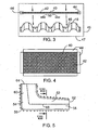
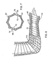
- FIG. 3 and 4 Illustrated in Figures 3 and 4 and also shown in Figure 6 is a thin layer of flexible mesh 40 which in an exemplary application of the above described venting material is extended over the second side having the protrusions.
- This mesh is formed so as to have numerous, very small apertures 42 formed therein, these apertures being sufficiently small to prevent surgical cast forming material from filling air gaps between the protrusions 24 and from filling or blocking the small holes 26 when the surgical cast is being formed.
- a protective edge trim 44 which can be made of a suitable, flexible, soft plastics material such as EVA.
- the edge trim has the effect of making the mesh easier and more comfortable to use and prevents the mesh from having sharp or uncomfortable edges.
- the mesh In an exemplary form of the mesh itself, it is very thin (about 0.3mm) and is therefore flexible.
- the mesh can be formed if necessary into a particular shape by thermoforming.
- the mesh can be made from a suitable plastic or metal. If the mesh is used in combination with an overlying or surrounding stockingnet material, both the mesh and the stockingnet will help to prevent the wet cast material from filling the wide gaps 46 between the protrusions and from filling the grooves 30.
- the mesh can optionally be either attached to the underlying venting material 16 or it can be unattached so that it can slide freely on top of the venting material. Leaving the mesh unattached can be advantageous if the venting material is covering a body part or limb having a relatively simple, cylindrical shape.
- the mesh generally needs to be bent in only one direction to conform to the shape of the venting material. It is possible to attach the mesh 40 to the venting material 16 by means of double sided tape 50 which per se is of standard construction.
- the pieces of tape 50 can be small, for example, 1 cm x 1 cm each. If the tape 50 is used, it is placed in the region of the longitudinal center of the mesh section. This allows the venting material to stretch and bend under the mesh layer while at the same time maintaining the mesh in the desired position relative to the venting material.
- a tube of stockingnet 45 can be used to hold the mesh 40 in place on top of the venting material.
- the stretchable, elastomeric material of the stockingnet can be pulled and stretched to place it over these two layers and then it will contract to hold the mesh in place.
- the inner side 47 of the stockingnet extends over the inside surface on the first side of the substrate forming the venting material.
- the venting material can also be cut or molded into sections adapted to fit around the body part or limb.
- the use of fitted sections of venting material can be particularly useful to cover body sections such as a foot or hand that can be difficult to cover uniformly and in a snug fitting manner by means of a spirally wound strip of venting material.
- Figure 5 illustrates the use of two half sections 52, 54 which have been molded or otherwise formed to fit around a person's elbow.
- the half section 52 is formed to fit around the inside corner of the elbow and to extend part way along the forearm and part way up the upper arm.
- the half section 54 covers the outside corner of the elbow at 56 and also extends part way along the forearm by means of end section 58 and part way along the upper arm by means of end section 60.
- the two half-sections 52, 54 both extend to a first end 62 and to a second end 64 of this venting device and they meet along two longitudinal joints 66, 68 with only the joint 68 being visible in Figure 5 .
- the joints 66, 68 are formed by wedge shaped or tapered longitudinal edges on each of the half sections 52, 54.
- the section 54 has wedge shaped edges at 70, 72.
- the edge 70 overlaps wedge-shaped edge 74 of the section 52 while the edge 72 overlaps the wedge-shaped edge 76.
- These wedge-shaped edges can provide for a smoother transition between the sections or, in other words, a smoother joint which is less likely to cause discomfort.
- the overlapping edges can be connected to one another in any of several different ways with the primary criteria being comfort to the patient. For example, it is possible to use a suitable strip of tape that will adhere to the venting material and that extends along the joint or it is possible to use a suitable adhesive.
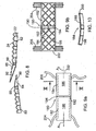
- FIG. 8 Another way of connecting the overlapping edges is illustrated in the detail view of Figure 8 which shows two adjacent sections of venting material 16 at 80 and 82.
- the wedge-shaped edge strips 84, 86 are connected to their respective substrates by means of a line of zig-zag stitching 88 which extends along the joint for the length of each edge strip.
- inner surfaces of the edge strips 84, 86 are strips of hook and loop type fasteners 90, 92.
- Fasteners of this known type are commonly sold under the trademark VELCRO.
- one of these strips 90, 92 has numerous, small hooks formed thereon while the other strip has numerous small loops formed thereon.
- edge strips 84, 86 can be made of a different, flexible material than the adjacent venting material sections 80, 82, the edge strips 84, 86 can be made of the same material, for example, EVA.
- Figure 1 also illustrates the use of similar wedge-shaped edge strips 94, 96 to connect together adjacent ends of cast venting devices, each formed of two half sections as described above.
- One of these cast venting devices covers an elbow portion of the patient's arm and it is indicated at 98.
- This venting device is similar to that described above in connection with Figure 5 .
- a straight, tubular venting device 100 is used to cover the wrist region and part of the forearm.
- the two half-sections which form the device 98 each have an edge strip 94 attached thereto at one end and the two half sections which make up the venting device 100 each have an edge strip 96 attached thereto.
- these edge strips 94, 96 can be attached by hook and loop or VELCRO TM type fasteners, if desired.
- each edge section or edge strip extends at a small acute angle to one another and, in an exemplary version of these edge strips, this acute angle does not exceed 30 degrees.
- Figure 1 also illustrates how air is able to enter and exit the space created by the venting devices 98, 100 under the cast 14.
- air is able to enter into or exit from the annular opening at 104, in this case, the opening surrounding the hand which is only partially covered by the cast 14. This air flow is indicated by the two way flow arrows A in the figure.
- air is able to enter into or exit from the annular opening 106 at the opposite end of the cast 14. Because of the presence of the protrusions 24 as well as the mesh 40 which covers these protrusions, there is an air gap 108 created between the inside of the cast and the outer surfaces of the venting devices and this air gap not only extends the length of the cast but also completely around the arm or other limb. In addition, this circulating air is able to reach the surface of the patient's skin by means of the numerous holes 26 through the venting material and the recesses 22.
- Figure 6 illustrates not only the use of an elongate strip of venting material which has been wound in a spiral fashion about a patient's arm but also the use of a tubular stockingnet 110 which is an optional feature that can be used either instead of the mesh 40 or in combination with the mesh 40.
- the stockingnet can be formed as one piece and can extend the entire length of the cast which is to be formed on the patient's limb or body. As the stockingnet is both stretchable and flexible, it can be made to fit closely about the exterior of the cast venting material, including any overlying mesh 40. As the use of such flexible tubes is known in the art, a detail description of its use and construction herein is deemed unnecessary. Reference can, for example, be made to applicant's US Patent No.
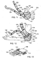
- FIG. 11 to 14 is intended for venting a region of a patient's limb which includes a section of the patient's limb having a bend therein.
- the venting device 110 has a flexible, main central portion 112 adapted to cover a major part of a first section 114 of the patient's limb which has the bend therein. As illustrated in Figure 12 , this bend can be formed at an elbow of a patient's arm 116.
- the central portion 112 as shown in Figure 12 is able to cover opposite side surfaces of the limb, including side surface 118 and a front or rear surface extending between the side surfaces.
- the venting device covers a rear surface of the elbow indicated at 120 and a bottom surface.
- the central portion may be constructed to cover a front surface of the knee area or a rear surface of the ankle/heel area.
- the venting device 110 also has two elongate, flexible connecting strips 124, 126 extending from and connected to two corners of the central portion located on opposite sides of the central portion. These corners are indicated at 128 and 130 in Figure 11 .
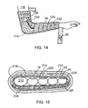
- Each of these strips 124, 126 is adapted and arranged to be wrapped in a spiral manner as shown in Figure 14 around a respective one of second and third sections of the patient's limb, these second and third sections being located at opposite ends of the first section 114 and adjacent thereto.
- connecting strip 124 it is wrapped around a second section of the arm comprising at least part of the forearm at 132 while the connecting strip 126 is wrapped around a third section 134 comprising part of the upper arm.
- the central portion 112 has at least a first side 136 and an opposite second side 138. These first and second sides during use of the venting device are positioned on opposite sides of the first section 114 of the patient's limb in order to provide ventilation thereto. Thus, these sides are formed to permit air circulation under a surgical cast that is formed over the venting device 110, this cast not being shown in the drawings but being of standard construction. The cast is formed over the venting device when the venting device has been arranged on the first, second and third sections of the patient's limb so as to substantially cover at least the major part of the first section of the limb.
- the exemplary form of the device also has a first end wall 140 which can be concavely curved on its inner side and a second end wall 142. These two end walls connect the first side 136 to the side wall 138 and these walls can be integrally formed as a single substrate of flexible material or can be connected to each other by suitable stitching (not shown).
- the central portion can have a relatively large aperture 144 formed therein between the first and second sides, this aperture being located on an outer side of the bend in the patient's limb during use of the venting device and provided to accommodate the bend in a comfortable manner.
- the central portion can be formed as a single, continuous substrate of venting material, without the aperture 144.
- the central portion 112 and the connecting strips 124, 126 are made of a waterproof, flexible substrate formed of a plastics material and having an inner side 146 and an outer side 148.
- This flexible substrate can in fact be the same flexible venting material as the material 16 described in detail above in conjunction with Figures 1, 2a and 2b .
- the inner side thus has a plurality, shallow, concave recesses 22 (only some of which are shown in Figures 11, 12 and 14 for ease of illustration) located over the device and the outer side 148 has a plurality of the protrusions 24 distributed over the substrate forming the device.
- each of the connecting strips can be integrally formed with at least one series of corrugations 152 which extend transversely across the respective connecting strip.
- each strip 124, 126 is provided with two or three series of corrugations. Each of these series enhances the ability of the respective strip to bend in a transverse direction in a plane extending parallel to the two opposite sides of the respective strip where the series of corrugations is located.
- each series of corrugations enables adjacent sections of the strip which are separated by the corrugations to bend relative to one another in the transverse direction.
- the first section 160 of the connecting strip 124 can extend at a different angle than the second section 162 because the corrugations 152 can be pulled out or stretched at one end more than the other end. This transverse bending ability increases the ability of the strip to wrap snugly around the limb or body part.
- Figure 13 illustrates how an extension strip 165 which can include a series of corrugations 152 as shown to an end section 166 of one of the connecting strips 124, 126.
- adjacent ends of the extension strip 165 and the connecting strip can be wedge shaped as indicated at 170 and 172.
- the wedge shaped ends can be connected together by means of an elastic adhesive covered band 174 which is able to stretch with the EVA material.
- zig-zag stitching can be used to attach the wedge-shaped edges or a suitable adhesive material.
- the two connecting strips 124, 126 at least are covered on their outer surfaces with thin mesh layers similar to that shown in Figures 3 and 4 , these mesh layers being held in position by tubes of stockingnet material (not shown) similar to the above described stockingnet 45.
- the surgical cast venting material is substantially prevented from filling the gaps formed between the protrusions 24.
- mesh material can also be applied over the exterior of the central portion 112 of the device and held in place by double-sided tape, for example.
- FIGS 1 , 9a, 9b and 10 illustrate one embodiment of a device for supporting a fractured limb of a patient, this device being indicated generally at 180.
- the device 180 can usefully be employed in combination with the above described venting materials and venting devices under a rigid cast.
- the supporting device includes two supporting plates 182, 184 adapted to and sized to support a fractured limb of a patient on one side of the fracture prior to application of a surgical cast.
- the plate has an inside surface 186 which is contoured so as to have a concave shape (see Figure 10 ) substantially matching the contour of the fractured limb in the region of the fracture and on the side of the fracture where the supporting device is to be used.
- each supporting plate is formed with a matching concave curve, as shown, this curve extending transversely across the plate.
- the supporting device 180 is placed against the exterior of the venting material substrate so as to press against the protrusions 24.
- the contour of the inside surface of the supporting plates can in fact be matched to the exterior contour of the shaped venting material.
- the two plates 182, 184 are adjustably connected together by means of a connector 190 which can be a threaded connector such as a suitable screw having a threaded shank and a head engagable with a tool such as a screw driver.
- the connector is movable from a locked position where no relative movement between the supporting plates occurs and an adjusting position which allows relative pivotal movement between central longitudinal axes of the supporting plates, these axes being indicated at A 1 and A 2 in Figure 9a .
- a surgical cast can be formed around the supporting device and the fractured limb while the supporting device is rigidly secured to one side of the fractured limb with the connector in the locked position (see Figure 1 ).
- one of the supporting plates for example, the plate 182
- a cylinder or sleeve 192 which can be integrally connected or otherwise connected to the inside end of the plate. Through this sleeve extends a first transversely extending passage through which the screw or connector 190 extends and from which a threaded shank of the screw extends.
- the other supporting plate for example, the plate 184, is also formed with a cylinder or sleeve 194 which is coaxial with the sleeve 192 for attachment purposes.
- the two sleeves can be formed with interlocking or telescoping adjacent ends to help hold them in a properly aligned position when they are being attached with the screw.
- the sleeve 194 forms a second, transversely extending passage which is threaded to receive the threaded shank of the screw or connector. It will be understood that by tightening the screw, the adjacent sides of the two sleeves can be clamped together to hold the two supporting plates in a selected position suitable for supporting the fractured limb.
- each of the plates 182, 184 Shown in Figures 9b and 10 is the outer surface of each of the plates 182, 184.
- the surface can have formed thereon a series of parallel and criss-crossing ribs 198.
- an edge flange 200 which, as shown in Figure 1 , can taper towards the outer end 202 of the plate.
- the opposite inside surface 186 of each supporting plate is made smooth so that the supporting device will not be uncomfortable for a patient when worn.
- the width of the supporting plates can vary depending upon their particular use or application but, in one exemplary embodiment of the device, the plates have a width of approximately 2 inches, this width being suitable for use of the device on a fractured arm.
- the supporting device 180 can be secured in place by means of straps 204, 206 attached to both of the supporting plates and sufficiently long to wrap around and be secured to the fractured limb.
- straps 204, 206 attached to both of the supporting plates and sufficiently long to wrap around and be secured to the fractured limb.
- a single long strap having a length sufficient to extend around the adjacent limb can be used.
- the strap or straps in a variety of ways, in one exemplary version of these straps, they are either fitted with or comprise hook and loop type fasteners which, as indicated, are commonly sold under the trade-mark VELCRO. These fasteners or fastener strips are used to detachably connect either adjacent ends of two strips together in order to secure the supporting device to the fractured limb or to secure the free end of a single long strap to the side or edge of the supporting
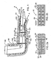
- FIG. 15 this figure illustrates a rigid cast 210 extending around a patient's foot which is indicated by the illustrated toes 212. It will be understood that the cast 210 can extend not only over part or all of the foot but also over the patient's ankle and part of his or her leg.
- the foot is surrounded initially by a relatively soft, absorbent cotton fabric or gauze 214.
- a relatively soft, absorbent cotton fabric or gauze 214 Such a material can be used whenever the present cast venting material is used, if desired, in order to increase the comfort of the patient.
- Extending over the cotton fabric is the venting material 16 which can be constructed as described above in conjunction with Figures 1, 2a and 2b .
- the underlying venting material can be supported by and rest against a rigid sole plate 216 which extends the width and length of the foot and which can be contoured to the patient's foot.
- a rigid sole plate 216 which extends the width and length of the foot and which can be contoured to the patient's foot.
- the use of such a sole plate in a walking cast is illustrated and described in applicant's published Canadian patent application No. 2,478,162 .
- the plate can be made of metal or a suitably rigid plastics material and it helps to protect both the foot (which may be fractured) and the cast (by spreading the user's weight over the rigid cast material). If the optional plate 216 is used, there is no need for the adjacent venting material to be covered by the above described mesh 40.
- the above described mesh 40 which can be a thermoformed mesh. Opposite side sections 218, 220 of the mesh extend down to the edges of the sole plate 216 and can be connected thereto, if desired. Again, the mesh 40 acts to prevent wet cast material from blocking or filling the network of air gaps between the protrusions 24.
- the protrusions 24 in the region underneath the foot can be made of a harder plastics material along with the adjacent layer or substrate of venting material to which they are integrally connected.
- the hardness of the material ranges from 18 - 25 DURA but the hardness of the EVA material forming the protrusions 24' and the adjacent substrate can be 30 DURA or more.
- Figure 15 also illustrates wedge shaped edges at 220 where opposite longitudinal edges of the substrate can be connected to each other. Again, the wedge edge sections can be fitted with VELCROTM for attachment purposes, as described above.
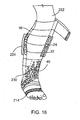
- Figure 16 illustrates the possible use of the present cast venting material on a lower leg, that is the portion of the leg below the patient's knee 222.
- the venting material 16 has been wrapped in a spiral fashion around the leg.
- a portion of the rigid cast is shown at 224.
- a thermoform mesh 40 Located between the cast and the venting material is a thermoform mesh 40 only a portion of which is shown in the ankle area.
- the venting material can extend over a layer of cotton fabric or gauze, this material being indicated at 214.
- the elastic stockingnet rests against the exterior of the mesh and helps to hold it in position as well as holding the venting material in position.
- the mesh sections can be thermoformed in sections which are generally semi-circular in transverse cross-section and which are formed to match the exterior shape of the underlying venting material. These semi-circular sections of mesh meet along a joint line indicated at 230.
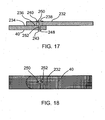
- Figures 17 and 18 illustrate how adjacent sections of the mesh 40 can be attached in an adjustable manner by means of a pin 243. It will be understood that the overall length of two or more mesh sections may need some final adjustment even after their initial forming and cutting. In addition, the angular relative position of two adjacent mesh sections may need to be adjusted or changed to accommodate the changing dimensions or curvature of the underlying venting material and body part.
- Figure 17 shows how adjacent end sections 232, 234 of the mesh can be overlapped at 236 and pivotably connected by means of the pin 243, which can be in the form of a cotter pin having two separable tines 238, 240 and a head 248. To allow some longitudinal adjustment one end section 232 can be formed with an elongate slot 250. The other end section 234 has a circular hole at 252 through which the tines are pushed before separation of their end sections as shown. The head and the tines should be made as small as possible so as not to cause discomfort to the cast wearer.
Landscapes
- Health & Medical Sciences (AREA)
- General Health & Medical Sciences (AREA)
- Engineering & Computer Science (AREA)
- Veterinary Medicine (AREA)
- Public Health (AREA)
- Life Sciences & Earth Sciences (AREA)
- Animal Behavior & Ethology (AREA)
- Biomedical Technology (AREA)
- Nursing (AREA)
- Orthopedic Medicine & Surgery (AREA)
- Heart & Thoracic Surgery (AREA)
- Vascular Medicine (AREA)
- Epidemiology (AREA)
- Materials Engineering (AREA)
- Chemical & Material Sciences (AREA)
- Orthopedics, Nursing, And Contraception (AREA)
Claims (7)
- Ein Material zur Belüftung von Gipsverbänden, bestehend aus:einem wasserfesten, flexiblen Trägermaterial bestehend aus einem Kunststoff mit einer ersten Seite, einer gegenüberliegenden zweiten Seite, einer Länge und einer Breite,wobei die genannte erste Seite über eine Vielzahl oberflächennaher, konkaver, über die gesamte Länge und Breite des Trägermaterials verteilter und in Abständen voneinander angeordneter Aushöhlungen verfügt,wobei die genannte zweite Seite über eine Vielzahl über die gesamte Länge und Breite des Trägermaterials verteilter und in Abständen voneinander angeordneter Ausbuchtungen verfügt, wobei mindestens ein Großteil der genannten Ausbuchtungen sich jeweils direkt gegenüber einer der genannten konkaven Aushöhlungen befindet und wobei die Ausbuchtungen bei Ansicht auf gleicher Ebene kreisförmig, quadratisch oder ellipsenförmig sind,wobei das genannte Trägermaterial mit einer Vielzahl relativ kleiner, über die gesamte Länge und Breite des Belüftungsmaterials verteilter Löcher perforiert ist,wobei das genannte Trägermaterial außerdem über Rillen auf der genannten zweiten Seite des Kunststoffmaterials zwischen den genannten Ausbuchtungen verfügt, wobei die genannten Rillen länglich sind, die Breite des Kunststoffmaterials verlängern und die Flexibilität des Trägermaterials erhöhen.
- Ein Material zur Belüftung von Gipsverbänden nach Anspruch 1, dadurch gekennzeichnet, dass das genannte Kunststoffmaterial Ethylvinylacetat ist.
- Ein Material zur Belüftung von Gipsverbänden nach Anspruch oder 2, dadurch gekennzeichnet, dass zumindest zwei einander gegenüberliegende Ränder des genannten Trägermaterials mit keilförmigen Randabschnitten ausgestattet sind, die sich entlang desselben erstrecken, wobei jeder Randabschnitt über die Außenkontur festlegende Randflächen verfügt, welche sich unter einem kleinen spitzen Winkel zueinander erstrecken, wobei der genannte spitze Winkel nicht mehr als 30 Grad sein soll.
- Ein Material zur Belüftung von Gipsverbänden nach Anspruch 3, dadurch gekennzeichnet, dass die genannten keilförmigen Randabschnitte auf einen verbleibenden Abschnitt des flexiblen Trägermaterials genäht sind.
- Ein Material zur Belüftung von Gipsverbänden nach Anspruch 3 oder 4, dadurch gekennzeichnet, dass jeder Randabschnitt mit einem daran befestigten Teil eines Klettverschlusses ausgestattet ist, womit der entsprechende Randabschnitt ablösbar mit einem daran anschließenden keilförmigen Randabschnitt verbunden werden kann.
- Ein Material zur Belüftung von Gipsverbänden nach einem der Ansprüchen bis 5, ausgestattet mit einer dünnen Schicht eines flexiblen Netzgewebes, welches sich über die genannte zweite Seite des Trägermaterials erstreckt und mit einer Vielzahl von Öffnungen ausgebildet ist, wobei die genannten Öffnungen klein genug sind, um zu verhindern, dass das Gipsmaterial die zwischen den genannten Ausbuchtungen gebildeten Luftlöcher füllt beziehungsweise bei der Formung des Gipsverbandes die genannten kleinen Löcher füllt oder blockiert.
- Ein Material zur Belüftung von Gipsverbänden nach Anspruch 6, ausgestattet mit einer Schlauchhülle aus Netzstrumpfmaterial, welche sowohl das genannte flexible Trägermaterial als auch das genannte Netzgewebe umschließt, sodass das genannte Netzgewebe auf der genannten zweiten Seite des Trägermaterials festgehalten wird, wobei die genannte Netzstrumpfhülle sich über die genannte erste Seite des Trägermaterials erstreckt.
Applications Claiming Priority (3)
| Application Number | Priority Date | Filing Date | Title |
|---|---|---|---|
| US89735007P | 2007-01-09 | 2007-01-09 | |
| US92961507P | 2007-07-05 | 2007-07-05 | |
| PCT/CA2008/000029 WO2008083477A1 (en) | 2007-01-09 | 2008-01-09 | Surgical cast venting device and material |
Publications (3)
| Publication Number | Publication Date |
|---|---|
| EP2107899A1 EP2107899A1 (de) | 2009-10-14 |
| EP2107899A4 EP2107899A4 (de) | 2011-12-28 |
| EP2107899B1 true EP2107899B1 (de) | 2014-06-11 |
Family
ID=39608284
Family Applications (1)
| Application Number | Title | Priority Date | Filing Date |
|---|---|---|---|
| EP08706194.1A Not-in-force EP2107899B1 (de) | 2007-01-09 | 2008-01-09 | Chirurgische gipsentlüftungsvorrichtung und material |
Country Status (5)
| Country | Link |
|---|---|
| US (2) | US8777883B2 (de) |
| EP (1) | EP2107899B1 (de) |
| AU (1) | AU2008204680B2 (de) |
| CA (1) | CA2689160C (de) |
| WO (1) | WO2008083477A1 (de) |
Families Citing this family (14)
| Publication number | Priority date | Publication date | Assignee | Title |
|---|---|---|---|---|
| EP2107899B1 (de) | 2007-01-09 | 2014-06-11 | Alessandro Barberio | Chirurgische gipsentlüftungsvorrichtung und material |
| CN102600000A (zh) * | 2012-04-12 | 2012-07-25 | 马胜忠 | 一种充气式石膏衬垫装置 |
| US9554944B2 (en) * | 2012-08-20 | 2017-01-31 | Alessandro Barberio | Medical protruded pads or dressings for wound care including use with orthopedic and prosthetic devices |
| US9527261B1 (en) | 2012-09-14 | 2016-12-27 | Hrl Laboratories, Llc | Hollow polymer micro-truss structures containing pressurized fluids |
| WO2014203049A1 (en) * | 2013-06-21 | 2014-12-24 | Alessandro Barberio | Medical protruded pads or dressings for wound care including use with orthopedic and prosthetic devices |
| US20150025430A1 (en) * | 2013-07-12 | 2015-01-22 | Brock Liden | Systems and methods for providing an orthopedic foot support |
| WO2015103708A1 (en) | 2014-01-10 | 2015-07-16 | Alessandro Barberio | Porous orthopedic or prosthetic support having removable cushioning and scaffolding layers |
| WO2017059533A1 (en) * | 2015-10-05 | 2017-04-13 | Alessandro Barberio | Wound dressing with elastic properties for contouring to the shape of a limb |
| US10517769B2 (en) | 2017-02-27 | 2019-12-31 | Christopher Steven Wood | Cast portal |
| JP2021508562A (ja) | 2017-12-26 | 2021-03-11 | バーベリオ、アレッサンドロ | 医療用ギプス及びその他の矯正器具用改良型筒状通気装置 |
| WO2020257910A1 (en) * | 2019-06-25 | 2020-12-30 | Alessandro Barberio | Improved orthopedic venting total contact cast to reduce edema and suffocation |
| US12042359B2 (en) | 2020-01-24 | 2024-07-23 | Elemental Orthopedics, LLC | Orthopedic cast ventilator |
| CN111728748B (zh) * | 2020-07-16 | 2022-03-25 | 川北医学院附属医院 | 一种骨科患者用的保护上肢动脉装置 |
| CN116392307B (zh) * | 2023-06-07 | 2023-08-25 | 中国人民解放军总医院第三医学中心 | 一种盆骨损伤紧急固定装置 |
Family Cites Families (36)
| Publication number | Priority date | Publication date | Assignee | Title |
|---|---|---|---|---|
| US2373802A (en) * | 1940-01-24 | 1945-04-17 | Anderson Roger | Surgical cast, cast material, and method |
| US3850167A (en) | 1973-08-09 | 1974-11-26 | W Seeley | Splint |
| FR2583636A1 (fr) | 1985-06-20 | 1986-12-26 | Meyrignac Henri | Pansement deshydratant |
| US4898160A (en) * | 1989-03-24 | 1990-02-06 | Alliance Group Inc. | Surgical cast venting device |
| US5507792A (en) * | 1990-09-05 | 1996-04-16 | Breg, Inc. | Therapeutic treatment device having a heat transfer element and a pump for circulating a treatment fluid therethrough |
| US5468219A (en) * | 1992-02-20 | 1995-11-21 | Crippen; Warren S. | Porous fiberglass cast system for the setting of broken appendages |
| US5916184A (en) * | 1998-01-28 | 1999-06-29 | Mckeel; William H. | Orthopedic airflow and water proof cast padding material and method of making a cast |
| US6482491B1 (en) | 1998-01-30 | 2002-11-19 | Coloplast A/S | Article having a surface showing adhesive properties |
| CA2254492C (en) | 1998-11-25 | 2003-12-09 | Alessandro Barberio | Surgical cast venting device |
| JP4329951B2 (ja) | 1999-01-25 | 2009-09-09 | 株式会社ケーブイケー | 逆止弁 |
| US6547751B1 (en) | 2000-01-03 | 2003-04-15 | Alessandro Barberio | Surgical cast venting device using stretchable net material |
| US6616622B1 (en) * | 2000-03-23 | 2003-09-09 | Alessandro Barberio | Surgical cast venting device |
| US20020115972A1 (en) | 2000-12-20 | 2002-08-22 | Shmuel Dabi | Absorbent article |
| CA2355041A1 (en) | 2001-04-02 | 2002-10-02 | Alessandro Barberio | Surgical cast venting device with padding |
| GB2387331B (en) | 2002-04-12 | 2005-03-23 | Johnson & Johnson Medical Ltd | Apertured hydrogel sheets |
| US20040127838A1 (en) | 2002-08-16 | 2004-07-01 | Inkslingers, Inc. | Article, system, and method of covering and protecting portions of human skin |
| JP3984156B2 (ja) | 2002-12-27 | 2007-10-03 | 最治子 鈴木 | 指先痛防止絆創膏 |
| US20040162511A1 (en) | 2003-02-13 | 2004-08-19 | Alessandro Barberio | Surgical cast venting device with padding |
| US7250034B2 (en) * | 2003-05-13 | 2007-07-31 | Alessandro Barberio | Venting devices for surgical casts and other orthopedic devices |
| US7229425B2 (en) * | 2003-09-12 | 2007-06-12 | Dunagan Rick D | Method and apparatus for aerating a cast |
| ZA200701053B (en) * | 2004-06-22 | 2008-12-31 | Bsn Medical Inc | Water resistant undercast padding |
| CA2478162C (en) | 2004-08-20 | 2013-03-12 | Alessandro Barberio | Orthopedic braces and casts with aerating arrangements |
| CA2478159A1 (en) | 2004-08-20 | 2006-02-20 | Alessandro Barberio | Aerating and pressure relieving devices for use with orthopedic casts |
| WO2006136024A1 (en) * | 2005-06-23 | 2006-12-28 | Alessandro Barberio | Cast venting devices made of two flexible layers |
| US8012112B2 (en) | 2006-02-14 | 2011-09-06 | Alessandro Aldo Barberio | Orthopedic braces and casts with aerating arrangements |
| DE102006017194B4 (de) | 2006-04-12 | 2010-11-04 | Birgit Riesinger | Flüssigkeitsdurchlässiger Primärverband |
| EP2107899B1 (de) | 2007-01-09 | 2014-06-11 | Alessandro Barberio | Chirurgische gipsentlüftungsvorrichtung und material |
| GB0719683D0 (en) | 2007-10-09 | 2007-11-21 | Brightwake Ltd | Wound dressing |
| JP5433222B2 (ja) | 2008-12-04 | 2014-03-05 | 株式会社瑞光 | 創傷被覆材 |
| TW201038258A (en) | 2009-04-21 | 2010-11-01 | Fortune Medical Instr Corp | Silica gel patch of rectifying scar |
| US20110270206A1 (en) | 2009-05-21 | 2011-11-03 | Jarl Jensen | Absorptive foam gel lock wound dressing |
| US8383227B2 (en) | 2010-01-28 | 2013-02-26 | Tredegar Film Products Corporation | Transfer layer for absorbent article |
| GB2477314B (en) | 2010-01-29 | 2016-10-19 | Su-Med Int (Uk) Ltd | Improvements in and relating to dressings |
| CN202960940U (zh) | 2012-12-22 | 2013-06-05 | 江西美宝利医用敷料有限公司 | 一种外科专用防粘脱脂纱布 |
| CN202844054U (zh) | 2013-01-02 | 2013-04-03 | 中南大学湘雅三医院 | 伤口/创面恒定负压治疗罩 |
| CN203122770U (zh) | 2013-01-31 | 2013-08-14 | 常州市中亚化工有限公司 | 一种伤口敷料 |
-
2008
- 2008-01-09 EP EP08706194.1A patent/EP2107899B1/de not_active Not-in-force
- 2008-01-09 WO PCT/CA2008/000029 patent/WO2008083477A1/en not_active Ceased
- 2008-01-09 US US12/448,897 patent/US8777883B2/en not_active Expired - Fee Related
- 2008-01-09 CA CA2689160A patent/CA2689160C/en not_active Expired - Fee Related
- 2008-01-09 AU AU2008204680A patent/AU2008204680B2/en not_active Ceased
-
2014
- 2014-06-20 US US14/310,180 patent/US9615957B2/en not_active Expired - Fee Related
Also Published As
| Publication number | Publication date |
|---|---|
| EP2107899A4 (de) | 2011-12-28 |
| EP2107899A1 (de) | 2009-10-14 |
| WO2008083477A1 (en) | 2008-07-17 |
| CA2689160C (en) | 2016-05-17 |
| AU2008204680A1 (en) | 2008-07-17 |
| US20140343471A1 (en) | 2014-11-20 |
| US8777883B2 (en) | 2014-07-15 |
| US9615957B2 (en) | 2017-04-11 |
| US20110152735A1 (en) | 2011-06-23 |
| CA2689160A1 (en) | 2008-07-17 |
| AU2008204680B2 (en) | 2013-04-04 |
Similar Documents
| Publication | Publication Date | Title |
|---|---|---|
| CA2689160C (en) | Surgical cast venting device and material | |
| US12121419B2 (en) | Thermoformable orthosis apparatus and method of use | |
| US8012112B2 (en) | Orthopedic braces and casts with aerating arrangements | |
| US10524936B2 (en) | Porous orthopedic or prosthetic support having removable cushioning and scaffolding layers | |
| US5180361A (en) | Antidecubitus immobilization cervical collar | |
| US6991612B2 (en) | Orthopedic splints | |
| US5445602A (en) | Flexible ankle brace | |
| US20060217649A1 (en) | Ankle brace | |
| US6547751B1 (en) | Surgical cast venting device using stretchable net material | |
| EP2500001A2 (de) | System und verfahren zur behandlung von schlafapnoe und schnarchen | |
| US20040162511A1 (en) | Surgical cast venting device with padding | |
| CA2467154C (en) | Improved venting devices for surgical casts and other orthopedic devices | |
| US20210154039A1 (en) | Waterproof, polymeric brace | |
| US20230381007A1 (en) | Orthopaedic device | |
| EP0005615A1 (de) | Schutzeinrichtung für Körperteile | |
| JP2000037409A (ja) | 足首装具 | |
| CA2563724A1 (en) | Splint or support with quick location technique | |
| CA2355041A1 (en) | Surgical cast venting device with padding | |
| WO2006136024A1 (en) | Cast venting devices made of two flexible layers | |
| CA2478162C (en) | Orthopedic braces and casts with aerating arrangements | |
| EP3091945B1 (de) | Poröse orthopädische oder prothetische stütze mit abnehmbaren polsterungs- und gerüstschichten | |
| JP2000037408A (ja) | 肘装具 | |
| US20220039984A1 (en) | Orthotic Device for Treating Plantar Fasciitis | |
| CA2348578A1 (en) | Surgical cast venting device with padding |
Legal Events
| Date | Code | Title | Description |
|---|---|---|---|
| PUAI | Public reference made under article 153(3) epc to a published international application that has entered the european phase |
Free format text: ORIGINAL CODE: 0009012 |
|
| 17P | Request for examination filed |
Effective date: 20090730 |
|
| AK | Designated contracting states |
Kind code of ref document: A1 Designated state(s): AT BE BG CH CY CZ DE DK EE ES FI FR GB GR HR HU IE IS IT LI LT LU LV MC MT NL NO PL PT RO SE SI SK TR |
|
| DAX | Request for extension of the european patent (deleted) | ||
| A4 | Supplementary search report drawn up and despatched |
Effective date: 20111124 |
|
| RIC1 | Information provided on ipc code assigned before grant |
Ipc: A61F 13/04 20060101AFI20111118BHEP Ipc: A61L 15/12 20060101ALI20111118BHEP Ipc: A61F 5/05 20060101ALI20111118BHEP |
|
| 17Q | First examination report despatched |
Effective date: 20120731 |
|
| GRAP | Despatch of communication of intention to grant a patent |
Free format text: ORIGINAL CODE: EPIDOSNIGR1 |
|
| INTG | Intention to grant announced |
Effective date: 20131212 |
|
| GRAS | Grant fee paid |
Free format text: ORIGINAL CODE: EPIDOSNIGR3 |
|
| GRAA | (expected) grant |
Free format text: ORIGINAL CODE: 0009210 |
|
| AK | Designated contracting states |
Kind code of ref document: B1 Designated state(s): AT BE BG CH CY CZ DE DK EE ES FI FR GB GR HR HU IE IS IT LI LT LU LV MC MT NL NO PL PT RO SE SI SK TR |
|
| REG | Reference to a national code |
Ref country code: GB Ref legal event code: FG4D |
|
| REG | Reference to a national code |
Ref country code: CH Ref legal event code: EP |
|
| REG | Reference to a national code |
Ref country code: IE Ref legal event code: FG4D |
|
| REG | Reference to a national code |
Ref country code: AT Ref legal event code: REF Ref document number: 671857 Country of ref document: AT Kind code of ref document: T Effective date: 20140715 |
|
| REG | Reference to a national code |
Ref country code: DE Ref legal event code: R096 Ref document number: 602008032689 Country of ref document: DE Effective date: 20140724 |
|
| PG25 | Lapsed in a contracting state [announced via postgrant information from national office to epo] |
Ref country code: GR Free format text: LAPSE BECAUSE OF FAILURE TO SUBMIT A TRANSLATION OF THE DESCRIPTION OR TO PAY THE FEE WITHIN THE PRESCRIBED TIME-LIMIT Effective date: 20140912 Ref country code: FI Free format text: LAPSE BECAUSE OF FAILURE TO SUBMIT A TRANSLATION OF THE DESCRIPTION OR TO PAY THE FEE WITHIN THE PRESCRIBED TIME-LIMIT Effective date: 20140611 Ref country code: LT Free format text: LAPSE BECAUSE OF FAILURE TO SUBMIT A TRANSLATION OF THE DESCRIPTION OR TO PAY THE FEE WITHIN THE PRESCRIBED TIME-LIMIT Effective date: 20140611 Ref country code: NO Free format text: LAPSE BECAUSE OF FAILURE TO SUBMIT A TRANSLATION OF THE DESCRIPTION OR TO PAY THE FEE WITHIN THE PRESCRIBED TIME-LIMIT Effective date: 20140911 |
|
| REG | Reference to a national code |
Ref country code: NL Ref legal event code: VDEP Effective date: 20140611 |
|
| REG | Reference to a national code |
Ref country code: AT Ref legal event code: MK05 Ref document number: 671857 Country of ref document: AT Kind code of ref document: T Effective date: 20140611 |
|
| REG | Reference to a national code |
Ref country code: LT Ref legal event code: MG4D |
|
| PG25 | Lapsed in a contracting state [announced via postgrant information from national office to epo] |
Ref country code: HR Free format text: LAPSE BECAUSE OF FAILURE TO SUBMIT A TRANSLATION OF THE DESCRIPTION OR TO PAY THE FEE WITHIN THE PRESCRIBED TIME-LIMIT Effective date: 20140611 Ref country code: LV Free format text: LAPSE BECAUSE OF FAILURE TO SUBMIT A TRANSLATION OF THE DESCRIPTION OR TO PAY THE FEE WITHIN THE PRESCRIBED TIME-LIMIT Effective date: 20140611 Ref country code: SE Free format text: LAPSE BECAUSE OF FAILURE TO SUBMIT A TRANSLATION OF THE DESCRIPTION OR TO PAY THE FEE WITHIN THE PRESCRIBED TIME-LIMIT Effective date: 20140611 |
|
| PG25 | Lapsed in a contracting state [announced via postgrant information from national office to epo] |
Ref country code: CZ Free format text: LAPSE BECAUSE OF FAILURE TO SUBMIT A TRANSLATION OF THE DESCRIPTION OR TO PAY THE FEE WITHIN THE PRESCRIBED TIME-LIMIT Effective date: 20140611 Ref country code: ES Free format text: LAPSE BECAUSE OF FAILURE TO SUBMIT A TRANSLATION OF THE DESCRIPTION OR TO PAY THE FEE WITHIN THE PRESCRIBED TIME-LIMIT Effective date: 20140611 Ref country code: PT Free format text: LAPSE BECAUSE OF FAILURE TO SUBMIT A TRANSLATION OF THE DESCRIPTION OR TO PAY THE FEE WITHIN THE PRESCRIBED TIME-LIMIT Effective date: 20141013 Ref country code: EE Free format text: LAPSE BECAUSE OF FAILURE TO SUBMIT A TRANSLATION OF THE DESCRIPTION OR TO PAY THE FEE WITHIN THE PRESCRIBED TIME-LIMIT Effective date: 20140611 Ref country code: SK Free format text: LAPSE BECAUSE OF FAILURE TO SUBMIT A TRANSLATION OF THE DESCRIPTION OR TO PAY THE FEE WITHIN THE PRESCRIBED TIME-LIMIT Effective date: 20140611 Ref country code: RO Free format text: LAPSE BECAUSE OF FAILURE TO SUBMIT A TRANSLATION OF THE DESCRIPTION OR TO PAY THE FEE WITHIN THE PRESCRIBED TIME-LIMIT Effective date: 20140611 |
|
| PG25 | Lapsed in a contracting state [announced via postgrant information from national office to epo] |
Ref country code: PL Free format text: LAPSE BECAUSE OF FAILURE TO SUBMIT A TRANSLATION OF THE DESCRIPTION OR TO PAY THE FEE WITHIN THE PRESCRIBED TIME-LIMIT Effective date: 20140611 Ref country code: AT Free format text: LAPSE BECAUSE OF FAILURE TO SUBMIT A TRANSLATION OF THE DESCRIPTION OR TO PAY THE FEE WITHIN THE PRESCRIBED TIME-LIMIT Effective date: 20140611 Ref country code: NL Free format text: LAPSE BECAUSE OF FAILURE TO SUBMIT A TRANSLATION OF THE DESCRIPTION OR TO PAY THE FEE WITHIN THE PRESCRIBED TIME-LIMIT Effective date: 20140611 Ref country code: IS Free format text: LAPSE BECAUSE OF FAILURE TO SUBMIT A TRANSLATION OF THE DESCRIPTION OR TO PAY THE FEE WITHIN THE PRESCRIBED TIME-LIMIT Effective date: 20141011 |
|
| REG | Reference to a national code |
Ref country code: DE Ref legal event code: R097 Ref document number: 602008032689 Country of ref document: DE |
|
| PLBE | No opposition filed within time limit |
Free format text: ORIGINAL CODE: 0009261 |
|
| STAA | Information on the status of an ep patent application or granted ep patent |
Free format text: STATUS: NO OPPOSITION FILED WITHIN TIME LIMIT |
|
| PG25 | Lapsed in a contracting state [announced via postgrant information from national office to epo] |
Ref country code: DK Free format text: LAPSE BECAUSE OF FAILURE TO SUBMIT A TRANSLATION OF THE DESCRIPTION OR TO PAY THE FEE WITHIN THE PRESCRIBED TIME-LIMIT Effective date: 20140611 |
|
| 26N | No opposition filed |
Effective date: 20150312 |
|
| REG | Reference to a national code |
Ref country code: DE Ref legal event code: R097 Ref document number: 602008032689 Country of ref document: DE Effective date: 20150312 |
|
| PG25 | Lapsed in a contracting state [announced via postgrant information from national office to epo] |
Ref country code: BE Free format text: LAPSE BECAUSE OF FAILURE TO SUBMIT A TRANSLATION OF THE DESCRIPTION OR TO PAY THE FEE WITHIN THE PRESCRIBED TIME-LIMIT Effective date: 20140611 |
|
| PG25 | Lapsed in a contracting state [announced via postgrant information from national office to epo] |
Ref country code: SI Free format text: LAPSE BECAUSE OF FAILURE TO SUBMIT A TRANSLATION OF THE DESCRIPTION OR TO PAY THE FEE WITHIN THE PRESCRIBED TIME-LIMIT Effective date: 20140611 |
|
| PG25 | Lapsed in a contracting state [announced via postgrant information from national office to epo] |
Ref country code: LU Free format text: LAPSE BECAUSE OF FAILURE TO SUBMIT A TRANSLATION OF THE DESCRIPTION OR TO PAY THE FEE WITHIN THE PRESCRIBED TIME-LIMIT Effective date: 20150109 |
|
| PG25 | Lapsed in a contracting state [announced via postgrant information from national office to epo] |
Ref country code: MC Free format text: LAPSE BECAUSE OF FAILURE TO SUBMIT A TRANSLATION OF THE DESCRIPTION OR TO PAY THE FEE WITHIN THE PRESCRIBED TIME-LIMIT Effective date: 20140611 |
|
| REG | Reference to a national code |
Ref country code: IE Ref legal event code: MM4A |
|
| PG25 | Lapsed in a contracting state [announced via postgrant information from national office to epo] |
Ref country code: IE Free format text: LAPSE BECAUSE OF NON-PAYMENT OF DUE FEES Effective date: 20150109 |
|
| REG | Reference to a national code |
Ref country code: FR Ref legal event code: PLFP Year of fee payment: 9 |
|
| PG25 | Lapsed in a contracting state [announced via postgrant information from national office to epo] |
Ref country code: MT Free format text: LAPSE BECAUSE OF FAILURE TO SUBMIT A TRANSLATION OF THE DESCRIPTION OR TO PAY THE FEE WITHIN THE PRESCRIBED TIME-LIMIT Effective date: 20140611 |
|
| REG | Reference to a national code |
Ref country code: FR Ref legal event code: PLFP Year of fee payment: 10 |
|
| PGFP | Annual fee paid to national office [announced via postgrant information from national office to epo] |
Ref country code: FR Payment date: 20170210 Year of fee payment: 10 |
|
| PG25 | Lapsed in a contracting state [announced via postgrant information from national office to epo] |
Ref country code: HU Free format text: LAPSE BECAUSE OF FAILURE TO SUBMIT A TRANSLATION OF THE DESCRIPTION OR TO PAY THE FEE WITHIN THE PRESCRIBED TIME-LIMIT; INVALID AB INITIO Effective date: 20080109 Ref country code: BG Free format text: LAPSE BECAUSE OF FAILURE TO SUBMIT A TRANSLATION OF THE DESCRIPTION OR TO PAY THE FEE WITHIN THE PRESCRIBED TIME-LIMIT Effective date: 20140611 |
|
| PG25 | Lapsed in a contracting state [announced via postgrant information from national office to epo] |
Ref country code: CY Free format text: LAPSE BECAUSE OF FAILURE TO SUBMIT A TRANSLATION OF THE DESCRIPTION OR TO PAY THE FEE WITHIN THE PRESCRIBED TIME-LIMIT Effective date: 20140611 |
|
| PG25 | Lapsed in a contracting state [announced via postgrant information from national office to epo] |
Ref country code: TR Free format text: LAPSE BECAUSE OF FAILURE TO SUBMIT A TRANSLATION OF THE DESCRIPTION OR TO PAY THE FEE WITHIN THE PRESCRIBED TIME-LIMIT Effective date: 20140611 |
|
| PGFP | Annual fee paid to national office [announced via postgrant information from national office to epo] |
Ref country code: CH Payment date: 20170721 Year of fee payment: 10 |
|
| PGFP | Annual fee paid to national office [announced via postgrant information from national office to epo] |
Ref country code: DE Payment date: 20180503 Year of fee payment: 11 |
|
| REG | Reference to a national code |
Ref country code: CH Ref legal event code: PL |
|
| PG25 | Lapsed in a contracting state [announced via postgrant information from national office to epo] |
Ref country code: FR Free format text: LAPSE BECAUSE OF NON-PAYMENT OF DUE FEES Effective date: 20180131 |
|
| REG | Reference to a national code |
Ref country code: FR Ref legal event code: ST Effective date: 20180928 |
|
| PG25 | Lapsed in a contracting state [announced via postgrant information from national office to epo] |
Ref country code: CH Free format text: LAPSE BECAUSE OF NON-PAYMENT OF DUE FEES Effective date: 20180131 Ref country code: LI Free format text: LAPSE BECAUSE OF NON-PAYMENT OF DUE FEES Effective date: 20180131 |
|
| PGFP | Annual fee paid to national office [announced via postgrant information from national office to epo] |
Ref country code: IT Payment date: 20190129 Year of fee payment: 12 Ref country code: GB Payment date: 20190210 Year of fee payment: 12 |
|
| REG | Reference to a national code |
Ref country code: DE Ref legal event code: R119 Ref document number: 602008032689 Country of ref document: DE |
|
| PG25 | Lapsed in a contracting state [announced via postgrant information from national office to epo] |
Ref country code: DE Free format text: LAPSE BECAUSE OF NON-PAYMENT OF DUE FEES Effective date: 20190801 |
|
| GBPC | Gb: european patent ceased through non-payment of renewal fee |
Effective date: 20200109 |
|
| PG25 | Lapsed in a contracting state [announced via postgrant information from national office to epo] |
Ref country code: GB Free format text: LAPSE BECAUSE OF NON-PAYMENT OF DUE FEES Effective date: 20200109 |
|
| PG25 | Lapsed in a contracting state [announced via postgrant information from national office to epo] |
Ref country code: IT Free format text: LAPSE BECAUSE OF NON-PAYMENT OF DUE FEES Effective date: 20200109 |