EP2107676A1 - Dispositif et procédé de contrôle pour un système de conversion de puissance ayant des fonctions de contre-mesure en cas de chute de tension instantanée et d'interruption de service - Google Patents
Dispositif et procédé de contrôle pour un système de conversion de puissance ayant des fonctions de contre-mesure en cas de chute de tension instantanée et d'interruption de service Download PDFInfo
- Publication number
- EP2107676A1 EP2107676A1 EP07850364A EP07850364A EP2107676A1 EP 2107676 A1 EP2107676 A1 EP 2107676A1 EP 07850364 A EP07850364 A EP 07850364A EP 07850364 A EP07850364 A EP 07850364A EP 2107676 A1 EP2107676 A1 EP 2107676A1
- Authority
- EP
- European Patent Office
- Prior art keywords
- electric power
- run
- alternating current
- current
- important load
- Prior art date
- Legal status (The legal status is an assumption and is not a legal conclusion. Google has not performed a legal analysis and makes no representation as to the accuracy of the status listed.)
- Withdrawn
Links
Images


Classifications
-
- H—ELECTRICITY
- H02—GENERATION; CONVERSION OR DISTRIBUTION OF ELECTRIC POWER
- H02J—CIRCUIT ARRANGEMENTS OR SYSTEMS FOR SUPPLYING OR DISTRIBUTING ELECTRIC POWER; SYSTEMS FOR STORING ELECTRIC ENERGY
- H02J9/00—Circuit arrangements for emergency or stand-by power supply, e.g. for emergency lighting
- H02J9/04—Circuit arrangements for emergency or stand-by power supply, e.g. for emergency lighting in which the distribution system is disconnected from the normal source and connected to a standby source
- H02J9/06—Circuit arrangements for emergency or stand-by power supply, e.g. for emergency lighting in which the distribution system is disconnected from the normal source and connected to a standby source with automatic change-over, e.g. UPS systems
- H02J9/062—Circuit arrangements for emergency or stand-by power supply, e.g. for emergency lighting in which the distribution system is disconnected from the normal source and connected to a standby source with automatic change-over, e.g. UPS systems for AC powered loads
-
- H—ELECTRICITY
- H02—GENERATION; CONVERSION OR DISTRIBUTION OF ELECTRIC POWER
- H02J—CIRCUIT ARRANGEMENTS OR SYSTEMS FOR SUPPLYING OR DISTRIBUTING ELECTRIC POWER; SYSTEMS FOR STORING ELECTRIC ENERGY
- H02J9/00—Circuit arrangements for emergency or stand-by power supply, e.g. for emergency lighting
- H02J9/04—Circuit arrangements for emergency or stand-by power supply, e.g. for emergency lighting in which the distribution system is disconnected from the normal source and connected to a standby source
- H02J9/06—Circuit arrangements for emergency or stand-by power supply, e.g. for emergency lighting in which the distribution system is disconnected from the normal source and connected to a standby source with automatic change-over, e.g. UPS systems
-
- H—ELECTRICITY
- H02—GENERATION; CONVERSION OR DISTRIBUTION OF ELECTRIC POWER
- H02M—APPARATUS FOR CONVERSION BETWEEN AC AND AC, BETWEEN AC AND DC, OR BETWEEN DC AND DC, AND FOR USE WITH MAINS OR SIMILAR POWER SUPPLY SYSTEMS; CONVERSION OF DC OR AC INPUT POWER INTO SURGE OUTPUT POWER; CONTROL OR REGULATION THEREOF
- H02M7/00—Conversion of ac power input into dc power output; Conversion of dc power input into ac power output
- H02M7/42—Conversion of dc power input into ac power output without possibility of reversal
- H02M7/44—Conversion of dc power input into ac power output without possibility of reversal by static converters
- H02M7/48—Conversion of dc power input into ac power output without possibility of reversal by static converters using discharge tubes with control electrode or semiconductor devices with control electrode
-
- H—ELECTRICITY
- H03—ELECTRONIC CIRCUITRY
- H03K—PULSE TECHNIQUE
- H03K17/00—Electronic switching or gating, i.e. not by contact-making and –breaking
- H03K17/16—Modifications for eliminating interference voltages or currents
- H03K17/161—Modifications for eliminating interference voltages or currents in field-effect transistor switches
Definitions
- the present invention relates to control device and control method for a power conversion system having functions of instantaneous voltage drop - service interruption counter-measure and, particularly, control device and control method for an alternating current-and-direct current conversion device which change a run mode from a system interconnection run to a self-contained run when an instantaneous voltage drop or a service interruption occurs.
- Fig. 2 shows one example of a power conversion system in which alternating current-and-direct current conversion device having the instantaneous voltage drop and service interruption counter-measure functions is equipped.
- 1 denotes the alternating current-and-direct current conversion device constituted by a DC/AC converter.
- a direct-current side of alternating current-and-direct current conversion device 1 is connected to a power storage section 2 such as a battery cell of a NaS (Natrium Sulfide) cell, a lead storage battery, lithium ion battery, and so forth and such as a capacitor of an electrolyte capacitor, an electric double layer capacitor, and so forth.
- 3 denotes an interconnection transformer.
- Alternating current-and-direct current conversion device 1 is connected to a power system 4 and an important load 5 via this interconnection transformer 3.
- 6 denotes a high-speed switch interposed in an electric passage connected to an electric power system 4, interconnection transformer 3, and important load 5.
- a power conversion system, hereinafter, called PCS) 10 is constituted by alternating current-and-direct current conversion device 1, power storage section 2, interconnection transformer 3, and a high-speed switch 6.
- an electric power is supplied from electric power system 4 to important load 5.
- a control device of PCS not shown in Fig. 2 opens high-speed switch 6 so that the electric power stored in power storage section 2 is supplied to important load 5 via alternating current-and-direct current conversion device 1 and interconnection transformer 3.
- a switch control permits a maintenance of the supply of electric power to important load 5 even if the instantaneous voltage drop or the service interruption is developed.
- instantaneous voltage drop and service interruption compensation device such a device as described above.
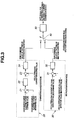
- Fig. 3 shows a switch control block diagram during the instantaneous voltage drop and service interruption of the above-described " instantaneous voltage drop and power interruption compensation device ".
- 21 denotes a deviation circuit which takes a deviation between a charge/discharge (electric) power command value and a charge/discharge (electric) power measured value, namely, a power detection value at a primary (winding) side (system side) of interconnection transformer 3 in Fig. 2 .
- 22 denotes an APR control circuit which performs a control, with an output of deviation circuit 21 as input, to make it coincide with the charge/discharge power command value.
- 23 denotes another deviation circuit which takes the deviation between an alternating current detection value which inputs into and outputs from alternating current-and-direct current conversion device 1 in Fig. 2 .
- 24 denotes an ACR control circuit which prepares a PWM command value of a current control, with an output of deviation circuit 23 as the input thereof.
- 31 denotes still another deviation circuit which takes the deviation between PCS alternating current voltage effective value command value and PCS alternating current voltage effective value measured value, namely, a voltage detection value (an system interconnection voltage which is the same as important load 5) at the primary (winding) side (a system side) of interconnection transformer 3 in Fig. 2 .
- 32 denotes an AVR control circuit which prepares an PWM command value to perform a coincidence control to make PCS alternating current voltage effective value coincident with its command value.
- deviation circuit 31 and AVR control circuit 32 constitute a self-contained run PWM command value preparing section 30 and AVR control circuit 32.
- 40 denotes a change switch which changes between charge/discharge run PWM command value preparing section 20 and self-contained run PWM command value preparing section 30 according to the charge-discharge run/self-contained run.
- PWM control section 50 denotes a PWM control section which is prepared for a PWM control signal, namely, a gate signal of alternating current-and-direct current conversion device 1 shown in Fig. 2 on a basis of a command value changed according to change switch 40.
- any one of three run modes of " charge run” during which an electric power of a power system is charged into power storage section 2, " discharge run” during which the electric power of the power storage section is discharged from power storage section 2, and " stand-by run " during which neither charge nor discharge is performed is carried out.
- charge/discharge run mode change switch 40 in Fig. 3 is switched to charge/discharge run PWM command value preparing section 20.
- a controller upon receipt of the charge/discharge electric power command value externally provided, performs a control (APR control) which makes the charge/discharge run PWM command value prepared coincident with the electric power command value. It should be noted that, during the stand-by run mode, this command value may be set to 0.
- the controller opens a passage of high-speed switch 6 shown in Fig. 2 and changes change switch 40 shown in Fig. 3 to self-contained run PWM command value preparing section 30, namely, self-contained run (AVR control).
- the self-contained run means that self-contained run discharges the electric power stored in electric power storage section 2 to make an effective value of PCS alternating current voltage coincident with the command value. This control permits a maintenance of the electric power supply to important load 5 even if the instantaneous voltage drop or the service interruption occurs.
- Non-patent document 1 PCS for NAS cell having functions of instantaneous voltage drop or service interruption counter-measure ( MEIDEN REVIEW, pages 22 to 25 of 2006 No. 3 ).
- FIG. 2 are designated by the like reference numerals as Fig. 2 .
- Power storage section 2 is shown with reference numeral 2 not shown in the drawings.
- Power storage section 2 is omitted in Figs. 5 through 7 and, in order to facilitate the explanation, a leakage inductance L only is denoted for interconnection transformer 3.
- high-speed switch 6 is opened for the run mode to be changed to " the self-contained run ".
- a current caused to flow through interconnection transformer 3 is varied sharply or abruptly from the charge current varied in accordance with a charge electric power command value to the discharge current varied in accordance with an important load capacity when the change from the charge run to the self-contained run is carried out.
- an abrupt variation of the current from zero current to the discharge current is carried out in accordance with the important load capacity.
- an object of the present invention to provide control device and control method for a power conversion system having instantaneous voltage drop - service interruption counter-measure functions which are capable of suppressing a variation of PCS alternating current voltage during a change operation to " the self-contained run " due to the instantaneous voltage drop or due to the service interruption.
- a control device for a power conversion system having instantaneous voltage drop -service interruption counter-measure functions as described in the claim 1 in order to solve the above-described task comprising: a high-speed switch interposed in an electric passage connected between an electric power system and an important load; an interconnection transformer having a primary winding side connected to a common junction between the high-speed switch and the important load; an alternating current-and-direct current conversion device having an alternating current side connected to a secondary winding side of the interconnection transformer and a direct current side connected to an electric power storage section and configured to perform a change of an electric power between the alternating current and the direct current; and control means for performing a constant current discharge run in which an electric power of the electric power storage section is discharged for a predetermined time duration at a predetermined constant current in order for an induced electromotive force due to a leakage inductance of an interconnection transformer developed during a change of a run mode to a self-contained run by means of the alternating current-and-direct current conversion device to
- control means performs the constant current discharge run during the switch from the system interconnection run to the self-contained run, namely, performs the discharge for the predetermined time duration for the predetermined constant current from the power storage section via the alternating current-and -direct current conversion apparatus.
- the constant current discharge run is carried out for the predetermined time period so that a current variation rate (di/dt) flowing through the interconnection during the change from system interconnection run to the self-contained run can be made small.
- a current variation rate (di/dt) flowing through the interconnection during the change from system interconnection run to the self-contained run can be made small.
- the induced electromagnetic force due to the leakage resistance according to the leakage inductance of the interconnection transformer can be suppressed.
- a stable power supply without an ill influence on the load is continued.
- the predetermined constant current discharged during the constant current discharge run is equal to the important load current.
- the predetermined constant current discharged when the constant current discharge run is carried out is equal to the important load current.
- the discharge current during the constant current discharge run is equal to an important load current and the voltage rise at the electric power system side of the high-speed switch developed when the high-speed switch is opened hardly occurs.
- the variation in PCS alternating current voltage during the change to the self-contained run can furthermore be reduced.
- the constant current discharge is performed during the switch from the system interconnection run to the self-contained run so that a current variation rate (di/dt) flowing through the interconnection transformer can be reduced.
- the induced electromotive force due to the leakage inductance of the interconnection transformer can be suppressed.
- a stable electric power supply is continued without an ill influence of a load by suppressing the variation of PCS alternating current voltage during the change to the self-contained run.
- the variation in PCS alternating current voltage is suppressed and the current increase in the high-speed switch due to the voltage reduction of the PCS alternating current voltage can be prevented.
- the voltage rise at the electric power system side of the high-speed switch developed when the high-speed switch is opened while the change to the self-contained run is carried out can be suppressed.
- the snubber circuit or the arrester device that has conventionally been required is not needed so that the space saving for the whole system and the cost saving can be achieved.
- the constant current discharged during the constant current discharge run is equal to the important load current.
- a current flowing through the high-speed switch can be suppressed to zero or remarkably to a large degree.
- the voltage rise at the electric power system side of the high-speed switch hardly occurs. Therefore, the variation in PCS alternating current voltage during the change to the self-contained run can more remarkably be reduced.
- PCS alternating current voltage variation during a change operation of the " self-contained run " is different according to the charge/discharge run mode.
- a primary (side) voltage of interconnection transformer 3 is reduced during " the charge run " and " the stand-by run”.
- the above-described primary (side) voltage of interconnection transformer 3 is reduced during the charge run or the stand-by run.
- the primary (side) voltage is reduced when the discharge capacity is smaller than the important load capacity, even during the discharge run.
- the primary (side) voltage thereof is raised when the discharge capacity is larger than the important load capacity.
- the instantaneous voltage drop or the service interruption is generated during the charge/discharge run mode.
- the constant current discharge run is carried out for an instantaneous time duration (for example, about 1.0 millisecond). Thereafter, “the self-contained run” is carried out so that the variation in the primary voltage can be suppressed. This is a principle according to the present invention.
- This method is effective for not only the charge run in Figs. 5(a) and 5(b) but also for the stand-by run or the discharge run in Figs. 6(a) to 7(b) .
- Fig. 1 is a control block diagram of control means representing a preferred embodiment according to the present invention.
- the same reference numerals shown in Fig. 1 as those in Fig. 3 designate like parts and its description will herein be omitted.
- change switch 25 is changed to the output side of APR control circuit 22, change switch 400 is continuously placed at the output side of charge/discharge run PWM command value preparing section 200. At this time, the state of the run (a system interconnection run according to the present invention) in the charge/discharge run mode occurs.
- change switch 25 is changed to the output side of self-contained run change prior current command value preparing section 60, which is continued to be positioned at the output side of charge/discharge run prior PWM command value preparing section 200 so as to perform the discharge control (a constant current discharge run) in response to the current command value of " the self-contained run change prior command value preparing section" 60 and this constant current discharge run is continued for an arbitrary setting time. Then, after the setting time has elapsed, change switch 400 is switched to the output side of " the self-contained run PWM command value preparing section 30 to perform the change to the " self-contained run ".
- the above-described " self-contained run change prior current command value" is, for example, set to any one of the values which is equal to the important load current; a device rated current which does not affect electric power system 4 nor important load 5 even if the important load capacity is equal to or lower than a device rating, since this mode interval of time is, as short as, for example, 1.0 millisecond; and a PWM modulation rate maximum value of alternating current-and-direct current conversion device 1 (since this mode interval of time is as short as, for example, 1.0 millisecond, no influence on electric power system 4 and important load 5 is given).
- the constant current discharge run is performed for a predetermined time duration.
- a current variation rate (di/dt) flowing through the interconnection transformer the induced electromotive force due to a presence of the leakage inductance of the interconnection transformer can be suppressed.
- V TR induced electromotive force
- a continuation time for the constant current discharge run is dependent upon to what degree the change time of the self-contained run is shortened or to what degree the voltage variation is suppressed.
- the value of voltage variation may be set to 0.1 milliseconds to 1.0 millisecond.
- the variation in the primary voltage (important load voltage) of interconnection transformer 3 can be suppressed.
- a current increase of the high-speed switch caused by the voltage drop of PCS alternating current voltage can be prevented.
- a voltage rise in an upper rank side of the high-speed switch caused by the voltage drop of PCS alternating current voltage can be prevented.
- the voltage rise at the upper rank side of the high-speed switch developed at the time of opening of the high-speed switch when the run mode is changed from the charge/discharge run mode to the instantaneous voltage drop and the service interruption can be suppressed. Consequently, the device for suppressing the high-speed switch such as a snubber circuit or arrester device conventionally required is not necessary. Then, these can contribute on space saving and cost reduction.
- the present invention is applicable not only to important load 5 but also to another load connected to the electric power system.
Landscapes
- Engineering & Computer Science (AREA)
- Power Engineering (AREA)
- Business, Economics & Management (AREA)
- Emergency Management (AREA)
- Stand-By Power Supply Arrangements (AREA)
- Inverter Devices (AREA)
- Supply And Distribution Of Alternating Current (AREA)
- Charge And Discharge Circuits For Batteries Or The Like (AREA)
Applications Claiming Priority (2)
| Application Number | Priority Date | Filing Date | Title |
|---|---|---|---|
| JP2007004082 | 2007-01-12 | ||
| PCT/JP2007/073796 WO2008084617A1 (fr) | 2007-01-12 | 2007-12-10 | Dispositif et procédé de contrôle pour un système de conversion de puissance ayant des fonctions de contre-mesure en cas de chute de tension instantanée et d'interruption de service |
Publications (2)
| Publication Number | Publication Date |
|---|---|
| EP2107676A1 true EP2107676A1 (fr) | 2009-10-07 |
| EP2107676A4 EP2107676A4 (fr) | 2014-06-25 |
Family
ID=39608516
Family Applications (1)
| Application Number | Title | Priority Date | Filing Date |
|---|---|---|---|
| EP07850364.6A Withdrawn EP2107676A4 (fr) | 2007-01-12 | 2007-12-10 | Dispositif et procédé de contrôle pour un système de conversion de puissance ayant des fonctions de contre-mesure en cas de chute de tension instantanée et d'interruption de service |
Country Status (8)
| Country | Link |
|---|---|
| US (1) | US8207632B2 (fr) |
| EP (1) | EP2107676A4 (fr) |
| JP (1) | JP4859932B2 (fr) |
| KR (1) | KR101009944B1 (fr) |
| CN (1) | CN101584108B (fr) |
| NZ (1) | NZ578994A (fr) |
| TW (1) | TWI350629B (fr) |
| WO (1) | WO2008084617A1 (fr) |
Cited By (1)
| Publication number | Priority date | Publication date | Assignee | Title |
|---|---|---|---|---|
| ITMI20130550A1 (it) * | 2013-04-09 | 2014-10-10 | Nicolas Tringali | Dispositivo per l'erogazione supplementare di energia. |
Families Citing this family (5)
| Publication number | Priority date | Publication date | Assignee | Title |
|---|---|---|---|---|
| JP5878393B2 (ja) * | 2012-02-17 | 2016-03-08 | 大和ハウス工業株式会社 | 電力供給システム |
| WO2018107384A1 (fr) * | 2016-12-14 | 2018-06-21 | 中车株洲电力机车有限公司 | Circuit principal de locomotive électrique et locomotive électrique |
| US10958082B2 (en) * | 2018-04-25 | 2021-03-23 | Microsoft Technology Licensing, Llc | Intelligent battery cycling for lifetime longevity |
| US11799302B2 (en) * | 2019-05-29 | 2023-10-24 | Toshiba Mitsubishi-Electric Industrial Systems Corporation | Power conversion system |
| CN111371173B (zh) * | 2020-03-13 | 2021-11-05 | 青海能高新能源有限公司 | 一种治理三相交流电压暂降的储充放系统及其方法 |
Citations (2)
| Publication number | Priority date | Publication date | Assignee | Title |
|---|---|---|---|---|
| WO1993012570A1 (fr) * | 1991-12-11 | 1993-06-24 | Best Power Technology, Inc. | Procede et appareil de charge de batteries d'un systeme d'alimentation de secours |
| US20060014054A1 (en) * | 2004-07-19 | 2006-01-19 | The Kansai Electric Power Co., Inc. | Stable power supplying apparatus |
Family Cites Families (18)
| Publication number | Priority date | Publication date | Assignee | Title |
|---|---|---|---|---|
| JPH0865904A (ja) * | 1994-06-06 | 1996-03-08 | Nippondenso Co Ltd | 電気自動車用充電装置 |
| US5646502A (en) * | 1995-08-28 | 1997-07-08 | Nsi Enterprises, Inc. | Emergency lighting circuit for shunt-regulated battery charging and lamp operation |
| US6087812A (en) * | 1997-06-13 | 2000-07-11 | Motorola, Inc. | Independent dual-switch system for extending battery life under transient loads |
| US5929538A (en) * | 1997-06-27 | 1999-07-27 | Abacus Controls Inc. | Multimode power processor |
| DE69831267T2 (de) * | 1997-11-25 | 2006-06-22 | Eaton Power Quality Corp., Cleveland | Ladeschaltung für usv |
| JP2002017045A (ja) * | 2000-06-29 | 2002-01-18 | Toshiba Battery Co Ltd | 二次電池装置 |
| US6366054B1 (en) * | 2001-05-02 | 2002-04-02 | Honeywell International Inc. | Method for determining state of charge of a battery by measuring its open circuit voltage |
| JP2004094607A (ja) * | 2002-08-30 | 2004-03-25 | Matsushita Electric Ind Co Ltd | 携帯情報機器、及びその充電状態最適化方法とプログラム、並びに、電池管理サーバ、及びそれによる電池式電気機器の充電状態最適化方法とプログラム |
| WO2004054065A1 (fr) | 2002-12-06 | 2004-06-24 | Electric Power Research Institute, Inc. | Alimentation en electricite sans interruption et systeme de generation |
| US7187531B1 (en) * | 2003-03-20 | 2007-03-06 | Tyco Electronics Power Systems, Inc. | Transient suppressor and power converter employing the same |
| JP2004312849A (ja) * | 2003-04-04 | 2004-11-04 | Sanyo Denki Co Ltd | 蓄電池劣化判定回路付無停電給電装置 |
| TW591844B (en) * | 2003-04-11 | 2004-06-11 | Delta Electronics Inc | Apparatus for providing battery charging circuit in a UPS system |
| JP3929449B2 (ja) * | 2004-03-29 | 2007-06-13 | 日新電機株式会社 | 無停電電源装置、及び停電補償システム |
| JP4314223B2 (ja) * | 2004-09-24 | 2009-08-12 | 株式会社東芝 | 回生用蓄電システム、蓄電池システムならびに自動車 |
| EP1750363A1 (fr) * | 2005-08-03 | 2007-02-07 | Abb Research Ltd. | Convertisseur alternatif continu à plusieurs niveaux pour des applications en traction |
| JP5068459B2 (ja) * | 2006-01-25 | 2012-11-07 | Necエナジーデバイス株式会社 | リチウム二次電池 |
| JP4304519B2 (ja) * | 2006-02-13 | 2009-07-29 | 富士電機システムズ株式会社 | 無停電電源装置 |
| JP4321584B2 (ja) * | 2006-12-18 | 2009-08-26 | ソニー株式会社 | 二次電池用負極および二次電池 |
-
2007
- 2007-12-10 US US12/521,161 patent/US8207632B2/en active Active
- 2007-12-10 JP JP2008553030A patent/JP4859932B2/ja active Active
- 2007-12-10 NZ NZ57899407A patent/NZ578994A/xx unknown
- 2007-12-10 KR KR1020097014385A patent/KR101009944B1/ko active IP Right Grant
- 2007-12-10 EP EP07850364.6A patent/EP2107676A4/fr not_active Withdrawn
- 2007-12-10 WO PCT/JP2007/073796 patent/WO2008084617A1/fr active Application Filing
- 2007-12-10 CN CN200780049746XA patent/CN101584108B/zh active Active
-
2008
- 2008-01-11 TW TW097101088A patent/TWI350629B/zh active
Patent Citations (2)
| Publication number | Priority date | Publication date | Assignee | Title |
|---|---|---|---|---|
| WO1993012570A1 (fr) * | 1991-12-11 | 1993-06-24 | Best Power Technology, Inc. | Procede et appareil de charge de batteries d'un systeme d'alimentation de secours |
| US20060014054A1 (en) * | 2004-07-19 | 2006-01-19 | The Kansai Electric Power Co., Inc. | Stable power supplying apparatus |
Non-Patent Citations (2)
| Title |
|---|
| HUNG J-C ET AL: "An active-clamp push-pull converter for battery sourcing applications", APPLIED POWER ELECTRONICS CONFERENCE AND EXPOSITION, 2005. APEC 2005. TWENTIETH ANNUAL IEEE AUSTIN, TX, USA 6-10 MARCH 2005, PISCATAWAY, NJ, USA,IEEE, US, vol. 2, 6 March 2005 (2005-03-06), page 1186, XP010809446, DOI: 10.1109/APEC.2005.1453151 ISBN: 978-0-7803-8975-5 * |
| See also references of WO2008084617A1 * |
Cited By (1)
| Publication number | Priority date | Publication date | Assignee | Title |
|---|---|---|---|---|
| ITMI20130550A1 (it) * | 2013-04-09 | 2014-10-10 | Nicolas Tringali | Dispositivo per l'erogazione supplementare di energia. |
Also Published As
| Publication number | Publication date |
|---|---|
| KR20090087959A (ko) | 2009-08-18 |
| EP2107676A4 (fr) | 2014-06-25 |
| NZ578994A (en) | 2012-08-31 |
| WO2008084617A1 (fr) | 2008-07-17 |
| TWI350629B (en) | 2011-10-11 |
| TW200841550A (en) | 2008-10-16 |
| US8207632B2 (en) | 2012-06-26 |
| JP4859932B2 (ja) | 2012-01-25 |
| JPWO2008084617A1 (ja) | 2010-04-30 |
| US20100007211A1 (en) | 2010-01-14 |
| CN101584108B (zh) | 2012-05-09 |
| KR101009944B1 (ko) | 2011-01-20 |
| CN101584108A (zh) | 2009-11-18 |
Similar Documents
| Publication | Publication Date | Title |
|---|---|---|
| EP3567711B1 (fr) | Module de suppression de courant d'appel, son procédé de commande et chargeur de bord bidirectionnel l'utilisant | |
| US8134342B2 (en) | Method for pulsed charging of a battery in an autonomous system comprising a supercapacitance | |
| US8716997B2 (en) | High power DC SSPC with capability of soft turn-on large capacitive loads | |
| KR100415747B1 (ko) | 엘리베이터의 제어장치 | |
| CN105406580B (zh) | 一种供电系统和方法 | |
| EP2504909B1 (fr) | Demarrage d'un champ photovoltaique avec haute tension à circuit ouvert | |
| US10135266B2 (en) | Battery system for motor vehicle with loss-free switching and automatic charge equalization | |
| CN100413175C (zh) | 通用电池充电器 | |
| US8207632B2 (en) | Control device for uninterruptible power supply | |
| US11616368B2 (en) | Power supply system including DC-to-DC converter and control method therefor | |
| US20110032652A1 (en) | Magnetic energy recovery switech having protective circuit | |
| CN106385101B (zh) | 一种大功率型电梯自动救援装置实现供电的方法及装置 | |
| EP3276815A1 (fr) | Appareil de conversion de courant | |
| CN203368016U (zh) | 一种过载限流保护电路 | |
| EP3633818B1 (fr) | Dispositif de conversion de puissance | |
| CN108767841B (zh) | 一种储能单元分离式变流器及控制方法 | |
| EP3996240A1 (fr) | Système d'alimentation | |
| CN108808834B (zh) | 在线式不间断电源及其控制方法 | |
| RU2678826C1 (ru) | Устройство накопления энергии | |
| JP2909820B2 (ja) | 交流無停電電源装置による負荷起動方法 | |
| CN114637357B (zh) | 故障检测方法、控制器、旁路稳压电路及存储介质 | |
| CN116647108A (zh) | 一种车载逆变电源过载快速限功率控制方法 | |
| JP4877092B2 (ja) | 分散型電源システム | |
| JP2000175376A (ja) | 通信機用電源装置の運転方法及び通信機用電源装置 | |
| CN206117498U (zh) | 变频器及其预充电装置 |
Legal Events
| Date | Code | Title | Description |
|---|---|---|---|
| PUAI | Public reference made under article 153(3) epc to a published international application that has entered the european phase |
Free format text: ORIGINAL CODE: 0009012 |
|
| 17P | Request for examination filed |
Effective date: 20090729 |
|
| AK | Designated contracting states |
Kind code of ref document: A1 Designated state(s): AT BE BG CH CY CZ DE DK EE ES FI FR GB GR HU IE IS IT LI LT LU LV MC MT NL PL PT RO SE SI SK TR |
|
| DAX | Request for extension of the european patent (deleted) | ||
| A4 | Supplementary search report drawn up and despatched |
Effective date: 20140522 |
|
| RIC1 | Information provided on ipc code assigned before grant |
Ipc: H02J 9/06 20060101ALI20140516BHEP Ipc: H02M 7/48 20070101AFI20140516BHEP |
|
| STAA | Information on the status of an ep patent application or granted ep patent |
Free format text: STATUS: EXAMINATION IS IN PROGRESS |
|
| 17Q | First examination report despatched |
Effective date: 20200716 |
|
| STAA | Information on the status of an ep patent application or granted ep patent |
Free format text: STATUS: EXAMINATION IS IN PROGRESS |
|
| RIC1 | Information provided on ipc code assigned before grant |
Ipc: H03K 17/16 20060101ALN20211220BHEP Ipc: H02J 9/06 20060101AFI20211220BHEP |
|
| GRAP | Despatch of communication of intention to grant a patent |
Free format text: ORIGINAL CODE: EPIDOSNIGR1 |
|
| STAA | Information on the status of an ep patent application or granted ep patent |
Free format text: STATUS: GRANT OF PATENT IS INTENDED |
|
| INTG | Intention to grant announced |
Effective date: 20220202 |
|
| RAP3 | Party data changed (applicant data changed or rights of an application transferred) |
Owner name: THE TOKYO ELECTRIC POWER COMPANY, INCORPORATED Owner name: MEIDENSHA CORPORATION |
|
| RIC1 | Information provided on ipc code assigned before grant |
Ipc: H03K 17/16 20060101ALN20220121BHEP Ipc: H02J 9/06 20060101AFI20220121BHEP |
|
| STAA | Information on the status of an ep patent application or granted ep patent |
Free format text: STATUS: THE APPLICATION IS DEEMED TO BE WITHDRAWN |
|
| 18D | Application deemed to be withdrawn |
Effective date: 20220614 |