EP2107573A2 - Structures de production radio-isotope, ensemble de carburant équipé de ces structures et procédés d'utilisation associés - Google Patents
Structures de production radio-isotope, ensemble de carburant équipé de ces structures et procédés d'utilisation associés Download PDFInfo
- Publication number
- EP2107573A2 EP2107573A2 EP09157186A EP09157186A EP2107573A2 EP 2107573 A2 EP2107573 A2 EP 2107573A2 EP 09157186 A EP09157186 A EP 09157186A EP 09157186 A EP09157186 A EP 09157186A EP 2107573 A2 EP2107573 A2 EP 2107573A2
- Authority
- EP
- European Patent Office
- Prior art keywords
- tie plate
- plate attachment
- fuel assembly
- attachment
- nuclear
- Prior art date
- Legal status (The legal status is an assumption and is not a legal conclusion. Google has not performed a legal analysis and makes no representation as to the accuracy of the status listed.)
- Granted
Links
Images


Classifications
-
- G—PHYSICS
- G21—NUCLEAR PHYSICS; NUCLEAR ENGINEERING
- G21G—CONVERSION OF CHEMICAL ELEMENTS; RADIOACTIVE SOURCES
- G21G1/00—Arrangements for converting chemical elements by electromagnetic radiation, corpuscular radiation or particle bombardment, e.g. producing radioactive isotopes
- G21G1/02—Arrangements for converting chemical elements by electromagnetic radiation, corpuscular radiation or particle bombardment, e.g. producing radioactive isotopes in nuclear reactors
-
- G—PHYSICS
- G21—NUCLEAR PHYSICS; NUCLEAR ENGINEERING
- G21C—NUCLEAR REACTORS
- G21C3/00—Reactor fuel elements and their assemblies; Selection of substances for use as reactor fuel elements
- G21C3/30—Assemblies of a number of fuel elements in the form of a rigid unit
- G21C3/32—Bundles of parallel pin-, rod-, or tube-shaped fuel elements
-
- Y—GENERAL TAGGING OF NEW TECHNOLOGICAL DEVELOPMENTS; GENERAL TAGGING OF CROSS-SECTIONAL TECHNOLOGIES SPANNING OVER SEVERAL SECTIONS OF THE IPC; TECHNICAL SUBJECTS COVERED BY FORMER USPC CROSS-REFERENCE ART COLLECTIONS [XRACs] AND DIGESTS
- Y02—TECHNOLOGIES OR APPLICATIONS FOR MITIGATION OR ADAPTATION AGAINST CLIMATE CHANGE
- Y02E—REDUCTION OF GREENHOUSE GAS [GHG] EMISSIONS, RELATED TO ENERGY GENERATION, TRANSMISSION OR DISTRIBUTION
- Y02E30/00—Energy generation of nuclear origin
- Y02E30/30—Nuclear fission reactors
Definitions
- Example embodiments generally relate to fuel structures and radioisotopes produced therein in nuclear power plants.
- nuclear power plants include a reactor core having fuel arranged therein to produce power by nuclear fission.
- a common design in U.S. nuclear power plants is to arrange fuel in a plurality of fuel rods bound together as a fuel assembly, or fuel assembly, placed within the reactor core. These fuel rods typically include several elements joining the fuel rods to assembly components at various axial locations throughout the assembly.
- a conventional fuel assembly 10 of a nuclear reactor may include an outer channel 12 surrounding an upper tie plate 14 and a lower tie plate 16.
- a plurality of full-length fuel rods 18 and/or part length fuel rods 19 may be arranged in a matrix within the fuel assembly 10 and pass through a plurality of spacers 20.
- Fuel rods 18 and 19 generally originate and terminate at upper and lower tie plates 14 and 16, continuously running the length of the fuel assembly 10, with the exception of part length rods 19, which all terminate at a lower vertical position from the full length rods 18.
- An upper end plug 15 and/or lower end plug 17 may join the fuel rods 18 and 19 to the upper and lower tie plates 14 and 16, with only the lower end plug 17 being used in the case of part length rods 19.
- Tie rods 28 may be full length rods placed at corner positions in fuel assembly 10 that securely join to upper and lower tie plates 14 and 16 and provide handling points for fuel assembly 10.
- the end plugs 15 and 17 may mate with, and in the case of tie rods 28, pass through, the upper and lower tie plates 14 and 16, respectively, and may secure fuel rods 18 or 19 axially in the fuel assembly 10.
- Example embodiments are directed to tie plate attachments having irradiation targets and fuel assemblies that use example embodiment tie plate attachments and methods of using the same to generate radioisotopes.
- Example embodiment tie plate attachments may include a plurality of retention bores that permit irradiation targets to be inserted and contained in the retention bores. The irradiation targets may be irradiated in an operating nuclear core including the fuel assemblies, generating useful radioisotopes that may be harvested from the spent nuclear fuel assembly by removing example embodiment tie plate attachments.
- Example embodiment tie plate attachments may be connected to fuel assemblies via the upper tie plate, fuel rods, and/or channel surrounding the fuel assembly.
- Example embodiment tie plates may be held at a fixed axial position within fuel assemblies so as to expose irradiation targets therein to constant, lower-level neutron flux, thereby converting a substantial amount of the irradiation targets into useable radioisotopes.
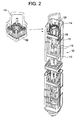
- FIG. 2 illustrates an example embodiment fuel assembly 100 including upper tie plate 114 and an example embodiment tie plate attachment 150 that individually or together may function as a radioisotope production structure.
- Example embodiment fuel assembly 100 may be similar to conventional fuel assemblies with the exception of including example embodiment tie plate attachment 150.
- example embodiment fuel assembly 100 is shown as similar to a conventional BWR type fuel assembly, other example embodiments, including PWR type fuel assemblies and unfinished fuel bundles, may be useable with tie plate attachments according to the present invention.
- Example embodiment tie plate attachment 150 may be generally rectangular and frame full-length fuel rods 118 in fuel assembly 100. An outer perimeter of example embodiment tie plate attachment 150 may extend to about an outer perimeter of fuel assembly 100 formed by fuel rods 118 so as to form a substantially uniform axial profile within example embodiment fuel assembly 100.
- example embodiment tie plate attachment 150 is shown as generally rectangular with a hollow center, other shapes are possible.
- example embodiment tie plate attachments may extend along only one or two sides of example embodiment fuel assemblies instead of all four sides.
- example embodiment tie plate attachments may have varied thicknesses or even extend through the entire cross-sectional profile of example embodiment fuel assemblies and have channels permitting coolant flow therethrough instead of having a hollow center.
- Example embodiment tie plate attachments may also have other shapes to match example embodiment fuel assemblies and tie plates therein, including hexagonal, triangular, etc. shapes.
- attachment 150 may have a cross-sectional edge thickness equal to a single row of fuel rods 118 along a transverse cross section of example embodiment fuel assembly 100. That is, example embodiment tie plate attachment 150 may surround, or be co-located with, the outer fuel rods 118 in example embodiment assembly 100. In this way, example embodiment tie plate attachment 150 may not significantly reduce or interfere with coolant flow through interior rods in assembly 100 and may be placed at a position with typically lower neutron flux within the assembly 100.
- example embodiment tie plate attachment 150 may be positioned under upper tie plate 114 in an axial direction.
- Example embodiment tie plate attachment 150 may be held under upper tie plate 114 in a variety of ways.
- example embodiment attachment 150 may be directly welded to upper tie plate 114, forged into or be otherwise structurally continuous with upper tie plate 114, may fit into upper tie plate 114 frictionally and/or in a lock-and-key fashion, or may be joined to upper tie plate 114 via fasteners such as bolts or screws.
- example embodiment tie plate attachment 150 may permit one or more fuel rods 118 and/or upper end and tie plugs 120 to pass axially through attachment 150 via holes 155 and into upper tie plate 114. Fuel rods 118 may thus fix example embodiment tie plate attachment 150 in a transverse position under upper tie plate 114.
- Example embodiment tie plate attachment 150 may be held in a constant axial position under tie plate 114 by fuel rods 118 seating into holes 155 or by flow of coolant through assembly 100 in an axial direction, and/or fixing example embodiment tie plate attachment 150 against upper tie plate 114.
- fuel rods 118 and/or upper end plugs 120 may be screwed into, locked into, welded onto, etc., example embodiment tie plate attachment 150 so as to hold attachment 150 in a constant axial position under upper tie plate 114.
- example embodiment tie plate attachment 150 may attach to outer channel 112 by being welded and/or removably fitted into outer channel 112 surrounding example embodiment fuel assembly 100. Lateral extensions (discussed below) may facilitate such contact between outer channel 112 and example embodiment tie plate attachment 150.
- example embodiment tie plate attachments may thus be held near or attached under an upper tie plate in the axial direction. This position affords easy access to example embodiment tie plate attachments during assembly disassembly, as the example embodiment tie plate attachment may be accessed with removal of the upper tie plate alone.
- FIG. 3 is a detailed illustration of an example embodiment tie plate attachment 150.
- example embodiment tie plate attachment 150 is shown as a hollow rectangle that matches the shape of the outer channel 112, other shapes and orientations are possible as discussed above.
- Example embodiment tie plate attachment 150 is fabricated of a material that substantially maintains its physical and neutronic properties when exposed to conditions in an operating nuclear core, such that example embodiment tie plate attachment 150 does not interfere with or affect the neutron flux present in the operating reactor.
- Example embodiment tie plate attachments may be fabricated of, for example, stainless steel, Inconel, a nickel alloy, a zirconium alloy, aluminum, etc.
- holes 155 may penetrate entirely through example embodiment tie plate attachment 150 and permit fuel rods 118 (shown in shadow) and/or upper end plugs 120 to pass through and/or connect to example embodiment tie plate attachment 150. As such, holes 155 may be sized with an inner diameter sufficiently greater than a fuel rod 118 and/or upper end plug 120 outer diameter.
- the example joining method of FIG. 3 shows example embodiment tie plate attachment 150 "sitting" on the shoulder 117 of the fuel rod 118 and upper end plug 120 joint. It is understood and several other joining methods discussed above and below may be used, including frictional contact between rods or end plugs and example embodiment tie plate attachments, lock-and-key, slot-type, or dovetail-type joints, welding, and/or continuous connection between the parts.
- Example embodiment tie plate attachment 150 may include one or more lateral extensions 165 that facilitate positioning relative to and/or connection with channel 112.
- lateral extensions 165 may connect or abut channel 112 on each side of example embodiment tie plate attachment 150 in order to center and/or secure example embodiment tie plate attachment 150 within example embodiment fuel assembly 100.
- Lateral extensions 165 may further match extensions and/or shape of the upper tie plate 114 in order to provide a consistent axial profile among upper tie plate 114 and example embodiment tie plate attachment 150.
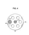
- Example embodiment tie plate attachment 150 includes a plurality of retaining bores 160 in its top face into which one or more irradiation targets 170 are placed and contained, as shown in FIG. 4 , which is a blown up portion of area A in FIG. 3 .
- Bores 160 do not pass through example embodiment tie plate attachment 150 but instead have a depth sufficient to allow irradiation targets 170 to fit within bores 160.
- Bores 160 may be geometrically placed around or between holes 155. Alternatively, bores 160 may be scattered in no particular pattern throughout example embodiment tie plate attachment 150, so long as the structural integrity of attachment 150 is not compromised by the position and/or number of bores 160.
- Irradiation targets 170 may be in the shape of small “seeds” or small rod shapes for insertion into retaining bores 160. Based on the size of bores 160, irradiation targets 170 may have a width and length to fit within bores 160 and may be, for example, on the scale of millimeters. Several irradiation targets 170 containing potentially different types of parent materials, including solids, liquids, and/or gasses, may be placed into a single retaining bore 160. Alternatively, each bore 160 may contain homogenous irradiation targets 170.
- Irradiation targets 170 may be made of a variety of materials that substantially convert into radioisotopes when exposed to a neutron flux encountered under tie plates 114 in an operating nuclear reactor. Because neutron flux may be lower at axial ends of example embodiment fuel assembly 100 ( FIG. 2 ), example embodiment tie plate attachments and irradiation targets 170 therein may be exposed to a lower flux as well. Hence, materials having high neutron cross sections and shorter half-lives may be preferable for use as irradiation targets 170, including, for example, Iridium-191, which may convert to Iridium-192 when exposed to neutron flux encountered in an operating nuclear reactor. Similarly, other isotopes, including Cobalt-59, Selenium-74, Strontium-88, and/or Iridium-191 for example, may be used as irradiation targets 170.
- Retention bores 160 may be sealed or closed by a cap 161, shown in Fig. 4 , that covers bores 160 and joins to example embodiment tie plate attachment 150.
- caps 161 may be welded onto attachment 150 or screwed into bores 160, if the bores 160 are threaded.
- Other methods of securely attaching caps 161 over bores 160 in order to provide containment of irradiation targets 170 may be known and useable with example embodiments.
- irradiation targets 170 may contain or produce useful gaseous, liquid, and/or solid radioisotopes when exposed to a neutron flux, and these radioisotopes may be contained in irradiation bores 160 by cap 161 even though they may be liquid, gaseous, or solid.
- example embodiment tie plate attachments Because of the higher axial position of example embodiment tie plate attachments, irradiation targets contained therein may be irradiated by lower amounts of neutron flux over a longer period of time, resulting in more predictable and effective generation of radioisotopes with shorter half lives from irradiation targets having higher cross sections. Further, because upper tie plate areas, where example embodiment tie plate attachments may be placed, are associated with low fretting, example embodiment tie plate attachments may provide robust containment for irradiation targets. Lastly, upper tie plates may be easily removed from irradiated example embodiment fuel assemblies without disturbing fuel rods or irradiated fuel, permitting easier harvesting of example embodiment tie plate attachments and useful radioisotopes therein. Example embodiment tie plate attachments may further provide robust containment for retaining and containing solid, liquid, or gas radioisotopes produced from irradiation targets in example embodiment tie plate attachments.
- example embodiments may be varied through routine experimentation and without further inventive activity.
- other fuel types, shapes, and configurations may be used in conjunction with example embodiment fuel assemblies and tie plate attachments.
- Variations are not to be regarded as departure from the spirit and scope of the exemplary embodiments, and all such modifications as would be obvious to one skilled in the art are intended to be included within the scope of the following claims.
Landscapes
- Physics & Mathematics (AREA)
- Engineering & Computer Science (AREA)
- Plasma & Fusion (AREA)
- General Engineering & Computer Science (AREA)
- High Energy & Nuclear Physics (AREA)
- Chemical & Material Sciences (AREA)
- Chemical Kinetics & Catalysis (AREA)
- General Chemical & Material Sciences (AREA)
- Particle Accelerators (AREA)
- Radiation-Therapy Devices (AREA)
- Monitoring And Testing Of Nuclear Reactors (AREA)
- Pressure Welding/Diffusion-Bonding (AREA)
Applications Claiming Priority (1)
| Application Number | Priority Date | Filing Date | Title |
|---|---|---|---|
| US12/078,705 US7970095B2 (en) | 2008-04-03 | 2008-04-03 | Radioisotope production structures, fuel assemblies having the same, and methods of using the same |
Publications (3)
| Publication Number | Publication Date |
|---|---|
| EP2107573A2 true EP2107573A2 (fr) | 2009-10-07 |
| EP2107573A3 EP2107573A3 (fr) | 2011-08-17 |
| EP2107573B1 EP2107573B1 (fr) | 2014-01-15 |
Family
ID=40823202
Family Applications (1)
| Application Number | Title | Priority Date | Filing Date |
|---|---|---|---|
| EP09157186.9A Not-in-force EP2107573B1 (fr) | 2008-04-03 | 2009-04-02 | Structures de production radio-isotope, assemblage de combustible équipé de ces structures et procédés d'utilisation associés |
Country Status (8)
| Country | Link |
|---|---|
| US (2) | US7970095B2 (fr) |
| EP (1) | EP2107573B1 (fr) |
| JP (1) | JP5421638B2 (fr) |
| CN (1) | CN101552045B (fr) |
| CA (1) | CA2661939A1 (fr) |
| ES (1) | ES2451504T3 (fr) |
| RU (1) | RU2481655C2 (fr) |
| TW (1) | TW200945368A (fr) |
Families Citing this family (8)
| Publication number | Priority date | Publication date | Assignee | Title |
|---|---|---|---|---|
| CN102137539A (zh) * | 2010-11-19 | 2011-07-27 | 成都中核高通同位素股份有限公司 | 用于反应堆辐照生产碘-125的氙气靶件及其制备方法 |
| US9196390B2 (en) * | 2011-09-23 | 2015-11-24 | Ge-Hitachi Nuclear Energy Americas Llc | Irradiation target encapsulation assembly and method of assembly |
| US10026515B2 (en) | 2015-05-06 | 2018-07-17 | Ge-Hitachi Nuclear Energy Americas Llc | Generating isotopes in an irradiation target holder installed in a nuclear reactor startup source holder position |
| CN105244069A (zh) * | 2015-08-31 | 2016-01-13 | 中科华核电技术研究院有限公司 | 高比活度放射源芯靶、放射性棒及新型阻流塞组件 |
| US10755829B2 (en) * | 2016-07-14 | 2020-08-25 | Westinghouse Electric Company Llc | Irradiation target handling device for moving a target into a nuclear reactor |
| RO134345A2 (ro) * | 2017-08-02 | 2020-07-30 | BWXT Isotope Technology Group, Inc. | Iradierea cu izotop a canalului de combustibil la centrala care funcţionează la putere maximă |
| CN111400869B (zh) * | 2020-02-25 | 2022-07-26 | 华南理工大学 | 一种堆芯中子通量时空演变预测方法、装置、介质及设备 |
| WO2022266487A1 (fr) * | 2021-06-18 | 2022-12-22 | BWXT Isotope Technology Group, Inc. | Cibles d'irradiation pour la production de radio-isotopes et outil de dégroupement pour leur désassemblage |
Citations (3)
| Publication number | Priority date | Publication date | Assignee | Title |
|---|---|---|---|---|
| FR2647945A1 (fr) * | 1989-06-02 | 1990-12-07 | Commissariat Energie Atomique | Dispositif de production de radio-isotopes notamment de cobalt 60 |
| US6233299B1 (en) * | 1998-10-02 | 2001-05-15 | Japan Nuclear Cycle Development Institute | Assembly for transmutation of a long-lived radioactive material |
| US20070133731A1 (en) * | 2004-12-03 | 2007-06-14 | Fawcett Russell M | Method of producing isotopes in power nuclear reactors |
Family Cites Families (53)
| Publication number | Priority date | Publication date | Assignee | Title |
|---|---|---|---|---|
| US3594275A (en) * | 1968-05-14 | 1971-07-20 | Neutron Products Inc | Method for the production of cobalt-60 sources and elongated hollow coiled wire target therefor |
| US3940318A (en) | 1970-12-23 | 1976-02-24 | Union Carbide Corporation | Preparation of a primary target for the production of fission products in a nuclear reactor |
| US3998691A (en) | 1971-09-29 | 1976-12-21 | Japan Atomic Energy Research Institute | Novel method of producing radioactive iodine |
| US4038137A (en) * | 1973-09-26 | 1977-07-26 | Exxon Nuclear Company, Inc. | Locking means for fuel bundles |
| US4196047A (en) | 1978-02-17 | 1980-04-01 | The Babcock & Wilcox Company | Irradiation surveillance specimen assembly |
| US4284472A (en) | 1978-10-16 | 1981-08-18 | General Electric Company | Method for enhanced control of radioiodine in the production of fission product molybdenum 99 |
| FR2481506B1 (fr) | 1980-04-25 | 1986-08-29 | Framatome Sa | Dispositif de cloisonnement du coeur d'un reacteur nucleaire par des elements amovibles |
| FR2513797A1 (fr) | 1981-09-30 | 1983-04-01 | Commissariat Energie Atomique | Dispositif de protection neutronique superieure pour assemblage de reacteur nucleaire |
| US4663111A (en) | 1982-11-24 | 1987-05-05 | Electric Power Research Institute, Inc. | System for and method of producing and retaining tritium |
| US4475948A (en) | 1983-04-26 | 1984-10-09 | The United States Of America As Represented By The Department Of Energy | Lithium aluminate/zirconium material useful in the production of tritium |
| US4532102A (en) | 1983-06-01 | 1985-07-30 | The United States Of America As Represented By The United States Department Of Energy | Producing tritium in a homogenous reactor |
| US4597936A (en) | 1983-10-12 | 1986-07-01 | Ga Technologies Inc. | Lithium-containing neutron target particle |
| CS255601B1 (en) | 1984-05-18 | 1988-03-15 | Kristian Svoboda | 99 mtc elution unit-built generator and method of its production |
| GB8422852D0 (en) | 1984-09-11 | 1984-11-07 | Atomic Energy Authority Uk | Heat pipe stabilised specimen container |
| US4729903A (en) | 1986-06-10 | 1988-03-08 | Midi-Physics, Inc. | Process for depositing I-125 onto a substrate used to manufacture I-125 sources |
| US4859431A (en) | 1986-11-10 | 1989-08-22 | The Curators Of The University Of Missouri | Rhenium generator system and its preparation and use |
| US5145636A (en) | 1989-10-02 | 1992-09-08 | Neorx Corporation | Soluble irradiation targets and methods for the production of radiorhenium |
| US5053186A (en) | 1989-10-02 | 1991-10-01 | Neorx Corporation | Soluble irradiation targets and methods for the production of radiorhenium |
| LU87684A1 (de) | 1990-02-23 | 1991-10-08 | Euratom | Verfahren zur erzeugung von aktinium-225 und wismut-213 |
| DE69119156T2 (de) | 1990-08-03 | 1997-01-09 | Toshiba Kawasaki Kk | Die Transmutation transuranischer Elemente ermöglichender Reaktorkern, die Transmutation transuranischer Elemente ermöglichender Brennstab und die Transmutation transuranischer Elemente ermöglichendes Brennstabbündel |
| US5596611A (en) | 1992-12-08 | 1997-01-21 | The Babcock & Wilcox Company | Medical isotope production reactor |
| GB2282478B (en) | 1993-10-01 | 1997-08-13 | Us Energy | Method of fabricating 99Mo production targets using low enriched uranium |
| US5633900A (en) | 1993-10-04 | 1997-05-27 | Hassal; Scott B. | Method and apparatus for production of radioactive iodine |
| US6490330B1 (en) | 1994-04-12 | 2002-12-03 | The Regents Of The University Of California | Production of high specific activity copper -67 |
| US5513226A (en) | 1994-05-23 | 1996-04-30 | General Atomics | Destruction of plutonium |
| US5871708A (en) | 1995-03-07 | 1999-02-16 | Korea Atomic Energy Research Institute | Radioactive patch/film and process for preparation thereof |
| JP3190005B2 (ja) | 1996-03-05 | 2001-07-16 | 日本原子力研究所 | 放射化ベリリウムのリサイクル方法 |
| US5682409A (en) | 1996-08-16 | 1997-10-28 | General Electric Company | Neutron fluence surveillance capsule holder modification for boiling water reactor |
| US5910971A (en) | 1998-02-23 | 1999-06-08 | Tci Incorporated | Method and apparatus for the production and extraction of molybdenum-99 |
| JP3781331B2 (ja) | 1998-06-05 | 2006-05-31 | 独立行政法人 日本原子力研究開発機構 | 血管再狭窄予防用キセノンー133の製造方法 |
| EP1227845A2 (fr) | 1999-11-09 | 2002-08-07 | Forschungszentrum Karlsruhe GmbH | Melange contenant des terres rares et utilisation |
| AUPQ641100A0 (en) | 2000-03-23 | 2000-04-15 | Australia Nuclear Science & Technology Organisation | Methods of synthesis and use of radiolabelled platinum chemotherapeutic ag ents |
| US6456680B1 (en) | 2000-03-29 | 2002-09-24 | Tci Incorporated | Method of strontium-89 radioisotope production |
| FR2811857B1 (fr) | 2000-07-11 | 2003-01-17 | Commissariat Energie Atomique | Dispositif de spallation pour la production de neutrons |
| US6678344B2 (en) | 2001-02-20 | 2004-01-13 | Framatome Anp, Inc. | Method and apparatus for producing radioisotopes |
| GB0104383D0 (en) | 2001-02-22 | 2001-04-11 | Psimedica Ltd | Cancer Treatment |
| EP1402540A1 (fr) | 2001-06-25 | 2004-03-31 | Umberto Di Caprio | Procede et installation de production d'energie nucleaire propre |
| US20030179844A1 (en) | 2001-10-05 | 2003-09-25 | Claudio Filippone | High-density power source (HDPS) utilizing decay heat and method thereof |
| CA2470006A1 (fr) | 2001-12-12 | 2003-07-03 | The University Of Alberta, The University Of British Columbia, Carleton University, Simon Fraser University And The University Of Victoria, Coll | Ion radioactif |
| US20040105520A1 (en) | 2002-07-08 | 2004-06-03 | Carter Gary Shelton | Method and apparatus for the ex-core production of nuclear isotopes in commercial PWRs |
| US6751280B2 (en) | 2002-08-12 | 2004-06-15 | Ut-Battelle, Llc | Method of preparing high specific activity platinum-195m |
| US6896716B1 (en) | 2002-12-10 | 2005-05-24 | Haselwood Enterprises, Inc. | Process for producing ultra-pure plutonium-238 |
| US20050105666A1 (en) | 2003-09-15 | 2005-05-19 | Saed Mirzadeh | Production of thorium-229 |
| EP1569243A1 (fr) * | 2004-02-20 | 2005-08-31 | Ion Beam Applications S.A. | Dispositif de cible pour la production d'un radioisotope |
| EP1659280A3 (fr) * | 2004-04-22 | 2008-11-26 | Keihin Corporation | Méthode pour commander le fonctionnement d'un moteur thermique |
| KR20060025076A (ko) | 2004-09-15 | 2006-03-20 | 동화약품공업주식회사 | 방사성필름의 제조방법 |
| US20060062342A1 (en) | 2004-09-17 | 2006-03-23 | Cyclotron Partners, L.P. | Method and apparatus for the production of radioisotopes |
| US7157061B2 (en) | 2004-09-24 | 2007-01-02 | Battelle Energy Alliance, Llc | Process for radioisotope recovery and system for implementing same |
| ATE468589T1 (de) | 2004-09-28 | 2010-06-15 | Soreq Nuclear Res Ct Israel At | Verfahren und system zur herstellung von radioisotopen |
| US7526058B2 (en) * | 2004-12-03 | 2009-04-28 | General Electric Company | Rod assembly for nuclear reactors |
| KR100728703B1 (ko) | 2004-12-21 | 2007-06-15 | 한국원자력연구원 | I-125 생산을 위한 내부 순환식 중성자 조사 용기 및 이를 이용한 i-125 생산방법 |
| US7235216B2 (en) | 2005-05-01 | 2007-06-26 | Iba Molecular North America, Inc. | Apparatus and method for producing radiopharmaceuticals |
| US20080076957A1 (en) | 2006-09-26 | 2008-03-27 | Stuart Lee Adelman | Method of producing europium-152 and uses therefor |
-
2008
- 2008-04-03 US US12/078,705 patent/US7970095B2/en not_active Expired - Fee Related
-
2009
- 2009-03-23 TW TW098109385A patent/TW200945368A/zh unknown
- 2009-03-26 CA CA002661939A patent/CA2661939A1/fr not_active Abandoned
- 2009-04-01 JP JP2009088588A patent/JP5421638B2/ja not_active Expired - Fee Related
- 2009-04-02 EP EP09157186.9A patent/EP2107573B1/fr not_active Not-in-force
- 2009-04-02 RU RU2009112217/07A patent/RU2481655C2/ru not_active IP Right Cessation
- 2009-04-02 ES ES09157186.9T patent/ES2451504T3/es active Active
- 2009-04-03 CN CN200910130402.2A patent/CN101552045B/zh not_active Expired - Fee Related
-
2011
- 2011-04-27 US US13/095,367 patent/US8576972B2/en not_active Expired - Fee Related
Patent Citations (3)
| Publication number | Priority date | Publication date | Assignee | Title |
|---|---|---|---|---|
| FR2647945A1 (fr) * | 1989-06-02 | 1990-12-07 | Commissariat Energie Atomique | Dispositif de production de radio-isotopes notamment de cobalt 60 |
| US6233299B1 (en) * | 1998-10-02 | 2001-05-15 | Japan Nuclear Cycle Development Institute | Assembly for transmutation of a long-lived radioactive material |
| US20070133731A1 (en) * | 2004-12-03 | 2007-06-14 | Fawcett Russell M | Method of producing isotopes in power nuclear reactors |
Also Published As
| Publication number | Publication date |
|---|---|
| JP2009250978A (ja) | 2009-10-29 |
| CN101552045B (zh) | 2014-08-06 |
| EP2107573B1 (fr) | 2014-01-15 |
| RU2481655C2 (ru) | 2013-05-10 |
| ES2451504T3 (es) | 2014-03-27 |
| EP2107573A3 (fr) | 2011-08-17 |
| US20100284503A1 (en) | 2010-11-11 |
| US8576972B2 (en) | 2013-11-05 |
| US7970095B2 (en) | 2011-06-28 |
| CA2661939A1 (fr) | 2009-10-03 |
| CN101552045A (zh) | 2009-10-07 |
| JP5421638B2 (ja) | 2014-02-19 |
| TW200945368A (en) | 2009-11-01 |
| US20110206175A1 (en) | 2011-08-25 |
| RU2009112217A (ru) | 2010-10-10 |
Similar Documents
| Publication | Publication Date | Title |
|---|---|---|
| US8576972B2 (en) | Radioisotope production structures, fuel assemblies having the same, and methods of using the same | |
| US7453972B2 (en) | Nuclear fuel assembly control rod drive thimble to bottom nozzle connector | |
| US7515674B2 (en) | Tube-in-tube threaded dashpot end plug | |
| EP2073214B1 (fr) | Barres de combustible disposant de pièces d'extrémité avec cible d'irradiation | |
| US20090274260A1 (en) | Irradiation target retention systems, fuel assemblies having the same, and methods of using the same | |
| US9202598B2 (en) | Fail-free fuel bundle assembly | |
| US20130272479A1 (en) | Lower end fitting for nuclear fuel assembly made from intersecting metal strips | |
| EP2109113B1 (fr) | Composant d'un assemblage de combustible de réacteur nucléaire détachable | |
| KR100969934B1 (ko) | 원거리에서 핵연료집합체 상단의 해체 및 조립의 편의성을증대시킨 상단고정체구조 | |
| US20100020916A1 (en) | Nuclear reactor fuel assembly grid | |
| KR101640942B1 (ko) | 원자로용 핵연료 집합체 | |
| JPH0631750B2 (ja) | 燃料集合体の上部ノズル取付構造 | |
| KR100906401B1 (ko) | 내부삽입관 회전 방지 장치가 설치된 해체 조립이 용이한상단고정체와 안내관의 체결구조 | |
| US4657733A (en) | Fuel assembly for a nuclear reactor |
Legal Events
| Date | Code | Title | Description |
|---|---|---|---|
| PUAI | Public reference made under article 153(3) epc to a published international application that has entered the european phase |
Free format text: ORIGINAL CODE: 0009012 |
|
| AK | Designated contracting states |
Kind code of ref document: A2 Designated state(s): AT BE BG CH CY CZ DE DK EE ES FI FR GB GR HR HU IE IS IT LI LT LU LV MC MK MT NL NO PL PT RO SE SI SK TR |
|
| PUAL | Search report despatched |
Free format text: ORIGINAL CODE: 0009013 |
|
| AK | Designated contracting states |
Kind code of ref document: A3 Designated state(s): AT BE BG CH CY CZ DE DK EE ES FI FR GB GR HR HU IE IS IT LI LT LU LV MC MK MT NL NO PL PT RO SE SI SK TR |
|
| AX | Request for extension of the european patent |
Extension state: AL BA RS |
|
| RIC1 | Information provided on ipc code assigned before grant |
Ipc: G21G 1/08 20060101ALI20110711BHEP Ipc: G21C 3/33 20060101AFI20110711BHEP |
|
| 17P | Request for examination filed |
Effective date: 20120217 |
|
| 17Q | First examination report despatched |
Effective date: 20120323 |
|
| REG | Reference to a national code |
Ref country code: DE Ref legal event code: R079 Ref document number: 602009021429 Country of ref document: DE Free format text: PREVIOUS MAIN CLASS: G21C0003330000 Ipc: G21C0003320000 |
|
| RIC1 | Information provided on ipc code assigned before grant |
Ipc: G21C 3/32 20060101AFI20130718BHEP Ipc: G21G 1/02 20060101ALI20130718BHEP |
|
| GRAP | Despatch of communication of intention to grant a patent |
Free format text: ORIGINAL CODE: EPIDOSNIGR1 |
|
| INTG | Intention to grant announced |
Effective date: 20130826 |
|
| GRAS | Grant fee paid |
Free format text: ORIGINAL CODE: EPIDOSNIGR3 |
|
| GRAA | (expected) grant |
Free format text: ORIGINAL CODE: 0009210 |
|
| AK | Designated contracting states |
Kind code of ref document: B1 Designated state(s): AT BE BG CH CY CZ DE DK EE ES FI FR GB GR HR HU IE IS IT LI LT LU LV MC MK MT NL NO PL PT RO SE SI SK TR |
|
| REG | Reference to a national code |
Ref country code: GB Ref legal event code: FG4D Ref country code: CH Ref legal event code: EP |
|
| REG | Reference to a national code |
Ref country code: AT Ref legal event code: REF Ref document number: 650136 Country of ref document: AT Kind code of ref document: T Effective date: 20140215 |
|
| REG | Reference to a national code |
Ref country code: IE Ref legal event code: FG4D |
|
| REG | Reference to a national code |
Ref country code: DE Ref legal event code: R096 Ref document number: 602009021429 Country of ref document: DE Effective date: 20140227 |
|
| REG | Reference to a national code |
Ref country code: ES Ref legal event code: FG2A Ref document number: 2451504 Country of ref document: ES Kind code of ref document: T3 Effective date: 20140327 |
|
| REG | Reference to a national code |
Ref country code: SE Ref legal event code: TRGR |
|
| REG | Reference to a national code |
Ref country code: NL Ref legal event code: VDEP Effective date: 20140115 |
|
| REG | Reference to a national code |
Ref country code: AT Ref legal event code: MK05 Ref document number: 650136 Country of ref document: AT Kind code of ref document: T Effective date: 20140115 |
|
| REG | Reference to a national code |
Ref country code: LT Ref legal event code: MG4D |
|
| PG25 | Lapsed in a contracting state [announced via postgrant information from national office to epo] |
Ref country code: IS Free format text: LAPSE BECAUSE OF FAILURE TO SUBMIT A TRANSLATION OF THE DESCRIPTION OR TO PAY THE FEE WITHIN THE PRESCRIBED TIME-LIMIT Effective date: 20140515 Ref country code: LT Free format text: LAPSE BECAUSE OF FAILURE TO SUBMIT A TRANSLATION OF THE DESCRIPTION OR TO PAY THE FEE WITHIN THE PRESCRIBED TIME-LIMIT Effective date: 20140115 Ref country code: NO Free format text: LAPSE BECAUSE OF FAILURE TO SUBMIT A TRANSLATION OF THE DESCRIPTION OR TO PAY THE FEE WITHIN THE PRESCRIBED TIME-LIMIT Effective date: 20140415 |
|
| PGFP | Annual fee paid to national office [announced via postgrant information from national office to epo] |
Ref country code: GB Payment date: 20140428 Year of fee payment: 6 |
|
| PG25 | Lapsed in a contracting state [announced via postgrant information from national office to epo] |
Ref country code: AT Free format text: LAPSE BECAUSE OF FAILURE TO SUBMIT A TRANSLATION OF THE DESCRIPTION OR TO PAY THE FEE WITHIN THE PRESCRIBED TIME-LIMIT Effective date: 20140115 Ref country code: NL Free format text: LAPSE BECAUSE OF FAILURE TO SUBMIT A TRANSLATION OF THE DESCRIPTION OR TO PAY THE FEE WITHIN THE PRESCRIBED TIME-LIMIT Effective date: 20140115 Ref country code: PT Free format text: LAPSE BECAUSE OF FAILURE TO SUBMIT A TRANSLATION OF THE DESCRIPTION OR TO PAY THE FEE WITHIN THE PRESCRIBED TIME-LIMIT Effective date: 20140515 Ref country code: CY Free format text: LAPSE BECAUSE OF FAILURE TO SUBMIT A TRANSLATION OF THE DESCRIPTION OR TO PAY THE FEE WITHIN THE PRESCRIBED TIME-LIMIT Effective date: 20140115 Ref country code: FI Free format text: LAPSE BECAUSE OF FAILURE TO SUBMIT A TRANSLATION OF THE DESCRIPTION OR TO PAY THE FEE WITHIN THE PRESCRIBED TIME-LIMIT Effective date: 20140115 |
|
| PGFP | Annual fee paid to national office [announced via postgrant information from national office to epo] |
Ref country code: SE Payment date: 20140429 Year of fee payment: 6 Ref country code: DE Payment date: 20140429 Year of fee payment: 6 Ref country code: ES Payment date: 20140428 Year of fee payment: 6 Ref country code: FR Payment date: 20140417 Year of fee payment: 6 |
|
| PG25 | Lapsed in a contracting state [announced via postgrant information from national office to epo] |
Ref country code: LV Free format text: LAPSE BECAUSE OF FAILURE TO SUBMIT A TRANSLATION OF THE DESCRIPTION OR TO PAY THE FEE WITHIN THE PRESCRIBED TIME-LIMIT Effective date: 20140115 Ref country code: HR Free format text: LAPSE BECAUSE OF FAILURE TO SUBMIT A TRANSLATION OF THE DESCRIPTION OR TO PAY THE FEE WITHIN THE PRESCRIBED TIME-LIMIT Effective date: 20140115 Ref country code: BE Free format text: LAPSE BECAUSE OF FAILURE TO SUBMIT A TRANSLATION OF THE DESCRIPTION OR TO PAY THE FEE WITHIN THE PRESCRIBED TIME-LIMIT Effective date: 20140115 |
|
| REG | Reference to a national code |
Ref country code: DE Ref legal event code: R097 Ref document number: 602009021429 Country of ref document: DE |
|
| PG25 | Lapsed in a contracting state [announced via postgrant information from national office to epo] |
Ref country code: CZ Free format text: LAPSE BECAUSE OF FAILURE TO SUBMIT A TRANSLATION OF THE DESCRIPTION OR TO PAY THE FEE WITHIN THE PRESCRIBED TIME-LIMIT Effective date: 20140115 Ref country code: EE Free format text: LAPSE BECAUSE OF FAILURE TO SUBMIT A TRANSLATION OF THE DESCRIPTION OR TO PAY THE FEE WITHIN THE PRESCRIBED TIME-LIMIT Effective date: 20140115 Ref country code: DK Free format text: LAPSE BECAUSE OF FAILURE TO SUBMIT A TRANSLATION OF THE DESCRIPTION OR TO PAY THE FEE WITHIN THE PRESCRIBED TIME-LIMIT Effective date: 20140115 Ref country code: RO Free format text: LAPSE BECAUSE OF FAILURE TO SUBMIT A TRANSLATION OF THE DESCRIPTION OR TO PAY THE FEE WITHIN THE PRESCRIBED TIME-LIMIT Effective date: 20140115 |
|
| PLBE | No opposition filed within time limit |
Free format text: ORIGINAL CODE: 0009261 |
|
| STAA | Information on the status of an ep patent application or granted ep patent |
Free format text: STATUS: NO OPPOSITION FILED WITHIN TIME LIMIT |
|
| PG25 | Lapsed in a contracting state [announced via postgrant information from national office to epo] |
Ref country code: SK Free format text: LAPSE BECAUSE OF FAILURE TO SUBMIT A TRANSLATION OF THE DESCRIPTION OR TO PAY THE FEE WITHIN THE PRESCRIBED TIME-LIMIT Effective date: 20140115 Ref country code: PL Free format text: LAPSE BECAUSE OF FAILURE TO SUBMIT A TRANSLATION OF THE DESCRIPTION OR TO PAY THE FEE WITHIN THE PRESCRIBED TIME-LIMIT Effective date: 20140115 Ref country code: LU Free format text: LAPSE BECAUSE OF FAILURE TO SUBMIT A TRANSLATION OF THE DESCRIPTION OR TO PAY THE FEE WITHIN THE PRESCRIBED TIME-LIMIT Effective date: 20140402 Ref country code: MC Free format text: LAPSE BECAUSE OF FAILURE TO SUBMIT A TRANSLATION OF THE DESCRIPTION OR TO PAY THE FEE WITHIN THE PRESCRIBED TIME-LIMIT Effective date: 20140115 |
|
| REG | Reference to a national code |
Ref country code: CH Ref legal event code: PL |
|
| 26N | No opposition filed |
Effective date: 20141016 |
|
| REG | Reference to a national code |
Ref country code: IE Ref legal event code: MM4A |
|
| PG25 | Lapsed in a contracting state [announced via postgrant information from national office to epo] |
Ref country code: LI Free format text: LAPSE BECAUSE OF NON-PAYMENT OF DUE FEES Effective date: 20140430 Ref country code: CH Free format text: LAPSE BECAUSE OF NON-PAYMENT OF DUE FEES Effective date: 20140430 |
|
| REG | Reference to a national code |
Ref country code: DE Ref legal event code: R097 Ref document number: 602009021429 Country of ref document: DE Effective date: 20141016 |
|
| PG25 | Lapsed in a contracting state [announced via postgrant information from national office to epo] |
Ref country code: IE Free format text: LAPSE BECAUSE OF NON-PAYMENT OF DUE FEES Effective date: 20140402 |
|
| PG25 | Lapsed in a contracting state [announced via postgrant information from national office to epo] |
Ref country code: SI Free format text: LAPSE BECAUSE OF FAILURE TO SUBMIT A TRANSLATION OF THE DESCRIPTION OR TO PAY THE FEE WITHIN THE PRESCRIBED TIME-LIMIT Effective date: 20140115 |
|
| REG | Reference to a national code |
Ref country code: DE Ref legal event code: R119 Ref document number: 602009021429 Country of ref document: DE |
|
| REG | Reference to a national code |
Ref country code: SE Ref legal event code: EUG |
|
| GBPC | Gb: european patent ceased through non-payment of renewal fee |
Effective date: 20150402 |
|
| PG25 | Lapsed in a contracting state [announced via postgrant information from national office to epo] |
Ref country code: DE Free format text: LAPSE BECAUSE OF NON-PAYMENT OF DUE FEES Effective date: 20151103 Ref country code: GB Free format text: LAPSE BECAUSE OF NON-PAYMENT OF DUE FEES Effective date: 20150402 |
|
| REG | Reference to a national code |
Ref country code: FR Ref legal event code: ST Effective date: 20151231 |
|
| PG25 | Lapsed in a contracting state [announced via postgrant information from national office to epo] |
Ref country code: FR Free format text: LAPSE BECAUSE OF NON-PAYMENT OF DUE FEES Effective date: 20150430 Ref country code: SE Free format text: LAPSE BECAUSE OF NON-PAYMENT OF DUE FEES Effective date: 20150403 |
|
| PG25 | Lapsed in a contracting state [announced via postgrant information from national office to epo] |
Ref country code: MT Free format text: LAPSE BECAUSE OF FAILURE TO SUBMIT A TRANSLATION OF THE DESCRIPTION OR TO PAY THE FEE WITHIN THE PRESCRIBED TIME-LIMIT Effective date: 20140115 |
|
| PG25 | Lapsed in a contracting state [announced via postgrant information from national office to epo] |
Ref country code: BG Free format text: LAPSE BECAUSE OF FAILURE TO SUBMIT A TRANSLATION OF THE DESCRIPTION OR TO PAY THE FEE WITHIN THE PRESCRIBED TIME-LIMIT Effective date: 20140115 Ref country code: GR Free format text: LAPSE BECAUSE OF FAILURE TO SUBMIT A TRANSLATION OF THE DESCRIPTION OR TO PAY THE FEE WITHIN THE PRESCRIBED TIME-LIMIT Effective date: 20140416 Ref country code: IT Free format text: LAPSE BECAUSE OF FAILURE TO SUBMIT A TRANSLATION OF THE DESCRIPTION OR TO PAY THE FEE WITHIN THE PRESCRIBED TIME-LIMIT Effective date: 20140115 |
|
| PG25 | Lapsed in a contracting state [announced via postgrant information from national office to epo] |
Ref country code: HU Free format text: LAPSE BECAUSE OF FAILURE TO SUBMIT A TRANSLATION OF THE DESCRIPTION OR TO PAY THE FEE WITHIN THE PRESCRIBED TIME-LIMIT; INVALID AB INITIO Effective date: 20090402 Ref country code: TR Free format text: LAPSE BECAUSE OF FAILURE TO SUBMIT A TRANSLATION OF THE DESCRIPTION OR TO PAY THE FEE WITHIN THE PRESCRIBED TIME-LIMIT Effective date: 20140115 |
|
| REG | Reference to a national code |
Ref country code: ES Ref legal event code: FD2A Effective date: 20161227 |
|
| PG25 | Lapsed in a contracting state [announced via postgrant information from national office to epo] |
Ref country code: ES Free format text: LAPSE BECAUSE OF NON-PAYMENT OF DUE FEES Effective date: 20150403 |
|
| PG25 | Lapsed in a contracting state [announced via postgrant information from national office to epo] |
Ref country code: MK Free format text: LAPSE BECAUSE OF FAILURE TO SUBMIT A TRANSLATION OF THE DESCRIPTION OR TO PAY THE FEE WITHIN THE PRESCRIBED TIME-LIMIT Effective date: 20140115 |