EP2107406A1 - Focal point detecting apparatus and microscope - Google Patents
Focal point detecting apparatus and microscope Download PDFInfo
- Publication number
- EP2107406A1 EP2107406A1 EP08703323A EP08703323A EP2107406A1 EP 2107406 A1 EP2107406 A1 EP 2107406A1 EP 08703323 A EP08703323 A EP 08703323A EP 08703323 A EP08703323 A EP 08703323A EP 2107406 A1 EP2107406 A1 EP 2107406A1
- Authority
- EP
- European Patent Office
- Prior art keywords
- light
- focus detection
- light source
- detection apparatus
- wavelength range
- Prior art date
- Legal status (The legal status is an assumption and is not a legal conclusion. Google has not performed a legal analysis and makes no representation as to the accuracy of the status listed.)
- Ceased
Links
- 238000001514 detection method Methods 0.000 claims abstract description 92
- 230000003287 optical effect Effects 0.000 claims description 47
- 238000012576 optical tweezer Methods 0.000 claims description 16
- 230000004907 flux Effects 0.000 claims description 6
- 230000005284 excitation Effects 0.000 claims description 5
- 239000011521 glass Substances 0.000 description 16
- 238000010586 diagram Methods 0.000 description 11
- 238000010276 construction Methods 0.000 description 9
- 238000003384 imaging method Methods 0.000 description 8
- 238000005286 illumination Methods 0.000 description 4
- 230000000694 effects Effects 0.000 description 3
- 239000007850 fluorescent dye Substances 0.000 description 2
- 238000000034 method Methods 0.000 description 2
- 239000006059 cover glass Substances 0.000 description 1
- 238000005516 engineering process Methods 0.000 description 1
Images


Classifications
-
- G—PHYSICS
- G02—OPTICS
- G02B—OPTICAL ELEMENTS, SYSTEMS OR APPARATUS
- G02B21/00—Microscopes
- G02B21/24—Base structure
- G02B21/241—Devices for focusing
- G02B21/245—Devices for focusing using auxiliary sources, detectors
-
- G—PHYSICS
- G02—OPTICS
- G02B—OPTICAL ELEMENTS, SYSTEMS OR APPARATUS
- G02B21/00—Microscopes
- G02B21/0004—Microscopes specially adapted for specific applications
- G02B21/002—Scanning microscopes
- G02B21/0024—Confocal scanning microscopes (CSOMs) or confocal "macroscopes"; Accessories which are not restricted to use with CSOMs, e.g. sample holders
- G02B21/0052—Optical details of the image generation
- G02B21/0076—Optical details of the image generation arrangements using fluorescence or luminescence
-
- G—PHYSICS
- G02—OPTICS
- G02B—OPTICAL ELEMENTS, SYSTEMS OR APPARATUS
- G02B21/00—Microscopes
- G02B21/32—Micromanipulators structurally combined with microscopes
-
- G—PHYSICS
- G02—OPTICS
- G02B—OPTICAL ELEMENTS, SYSTEMS OR APPARATUS
- G02B21/00—Microscopes
- G02B21/16—Microscopes adapted for ultraviolet illumination ; Fluorescence microscopes
Definitions
- the present invention relates to a focus detection apparatus and a microscope.
- focus detection apparatuses for a biological microscope such as a technique that keeps focusing by detecting a glass interface in the vicinity of a sample using reflection of infrared light (for example, see Japanese Patent Application Laid-Open No. 2004-070276 ) is extremely effective upon performing an observation together with a dosage or a long time observation, or a continuous observation of a plurality of positions of a sample.
- the wavelength of observation light is not limited to visible light, so that light having a wavelength range of near-infrared cannot be exclusively used for focus detection and keeping thereof.
- the present invention is made in view of the aforementioned problems, and has an object to provide a focus detection apparatus that limits a wavelength range of light used for the focus detection and uses broader wavelength range except the wavelength of focus detection for microscope observation and other purposes than the focus detection, and a microscope equipped therewith.
- a focus detection apparatus comprising: a light source that emanates light with a given wavelength range; and an optical member that reflects focus detection light with a given wavelength range in order to detect focus shift between an objective lens and an object to be observed in a microscope, and transmits non-focus detection light with at least two wavelength ranges except the given wavelength range.
- the wavelength range of the light that is emanated from the light source and reflected by the optical member is located between two wavelength ranges of light that comes from the object to be observed and transmits the optical member.
- the optical member is a partial mirror that reflects marginal light flux of the light with the given wavelength range to lead to the object to be observed, and transmits the rest of the light flux.
- the light source selectively emanates light with a plurality of different wavelength ranges
- the optical member is a dichroic mirror unit equipped with a plurality of dichroic mirrors that are corresponding to the light with the plurality of different wavelength ranges emanated from the light source, and removably movable into an optical path.
- the light source selectively emanates light with a plurality of different wavelength ranges.
- the focus detection apparatus preferably further comprising the light source that emanates light with a given wavelength range for illuminating the object to be observed for focus detection.
- the focus detection apparatus preferably further comprises a photodetector that detects reflected light of the light source reflected by the object to be observed.
- the focus detection apparatus preferably further comprises a controller that detects focus shift between the objective lens and the object to be observed in the microscope on the basis of a signal from the photodetector.
- the focus detection apparatus preferably further comprises a second light source that emanates the non-focus detection light.
- the focus detection apparatus preferably further comprises a second optical member that reflects light emanated from the second light source to the object to be observed and transmits light from the object to be observed.
- the first light source emanates light with an infrared wavelength range
- the second light source emanates light with a longer wavelength range than the infrared wavelength range
- a microscope equipped with the focus detection apparatus according to the first aspect.
- the microscope includes an objective lens and a camera attaching portion, the optical member and the second optical member are disposed on the optical path between the objective lens and the camera attaching portion, the optical member is disposed to the objective lens side, and the second optical member is disposed to the camera attaching portion side.
- the second light source is a light source of an optical tweezers.
- the second light source is a light source of a two-photon excitation.
- the first light source emanates light with an infrared wavelength range
- the second light source emanates light with a longer wavelength range than the infrared wavelength range
- the present invention makes it possible to provide a focus detection apparatus that limits a wavelength range of light used for the focus detection and uses broader wavelength range except the wavelength of focus detection for microscope observation and other purposes than the focus detection, and a microscope equipped therewith.
- Fig. 1 is a diagram showing a whole construction of a microscope equipped with a focus detection apparatus according to a first embodiment of the present invention.
- the microscope 1 is composed of a microscope body 2, a focus detection apparatus 3, and an optical tweezers optical system 4.
- non-defocus-detection light light except the light using for focus detection is called non-defocus-detection light.
- this non-defocus-detection light there are optical-tweezers light, multi-photon-excitation light, and, for example, fluorescence light from an object to be observed in the fluorescence observation.
- a light source emanating optical-tweezers light and multi-photon-excitation light is called as a second light source.
- the microscope body 2 is equipped with a stage 7 on which a sample 6 put between a cover glass 5a and a slide glass 5b is placed, and in order from the stage 7 side, an objective lens 8, an imaging lens 9, and a camera 10.
- an illumination light source (not shown) that emanates illumination light for illuminating the sample 6 including the wavelength ⁇ FL1 , ⁇ FL2 , ⁇ FL3 which are shorter than a wavelength ⁇ IR1 of near-infrared light explained later.
- the objective lens 8 is electrically movable in a direction up and down by an objective lens driver (not shown).
- the optical tweezers optical system 4 is equipped with a laser light source 11, and in order from the laser light source 11 side, a lens 12, mirrors 13a, 13b, and a semi-transparent mirror 14.
- the semi-transparent mirror 14 is disposed on an optical path between the objective lens 8 and the imaging lens 9 in the microscope body 2, so that laser light emanated from the laser light source 11 can be led to the optical path in the microscope body 2 to illuminate the sample 6.
- the microscope body 2 light from the sample 6 illuminated by an illumination light source (not shown) passes through the objective lens 8, a dichroic mirror 15 explained later, and the semi-transparent mirror 14 in this order, and forms an image on an imaging surface of the camera 10 by the imaging lens 9. Accordingly, the camera 10 can take an image of the sample 6, and an observer can observe the taken image of the sample 6 through a monitor (not shown) (hereinafter called as "ordinary observation").
- optical tweezers optical system 4 laser light emanated from the laser light source 11 is reflected by the mirrors 13a, 13b through the lens 12, led to the semi-transparent mirror 14 in the microscope body 2.
- the laser light is reflected by the semi-transparent mirror 14, and after passing through the dichroic mirror 15 explained later illuminates the sample 6 through the objective lens 8. Accordingly, the observer can carry out the optical tweezers operation to the sample 6 (hereinafter called as "optical tweezers observation").
- the focus detection apparatus 3 is equipped with an IR light source 16 that emanates light with a given wavelength range and, in order from the IR light source 16 side, a lens 17, a half-mask 18, a semi-transparent mirror 19, and the dichroic mirror 15, and on the reflection optical path of the semi-transparent mirror 19, there are provided with an imaging lens 20, and a photodetector 21.
- the dichroic mirror 15 is disposed on the optical path between the objective lens 8 and the semi-transparent mirror 14 in the microscope body 2, so that the dichroic mirror 15 can lead the light from the IR light source 16 to the optical path of the microscope body 2.
- the dichroic mirror 15 according to the present embodiment has a characteristic that reflects only certain light emanated from the IR light source 16 with a given wavelength range, in other words, only near-infrared light with the wavelength ⁇ IR1 .
- Fig. 2 is a graphs showing reflection characteristic of a dichroic mirror 15 of the focus detection apparatus 3 according to the first embodiment of the present invention.
- the focus detection apparatus 3 light emanated from the IR light source 16 with a given wavelength range passes through the lens 17, the half mask 18, and the semi-transparent mirror 19 in this order, and is reflected by the dichroic mirror 15 to the sample 6 side. After passing through the objective lens 8, the light is reflected by a glass interface 6a in the vicinity of the sample 6. The reflected light of the IR light source 16 reflected by the glass interface 6a is reflected again by the dichroic mirror 15 in the IR light source 16 direction, and after reflected by the semi-transparent mirror 19 forms an image on a detecting surface of the photodetector 21 through the imaging lens 20.
- a controller 22 installed in the focus detection apparatus 3 detects the position in the optical axis direction of the glass interface 6a on the basis of the detected signal of the photodetector 21, in other words, defocus between the objective lens 8 and the glass interface 6a is detected, and the objective lens 8 is driven by the objective driver (not shown) installed in the microscope body 2, so that the glass interface 6a is disposed on the focus position of the objective lens 8. Accordingly, focusing on the sample 6 is accomplished in the microscope body 2. Since the above-described focusing operation is always carried out upon observation, the state of focusing on the sample 6 is kept upon observation. Accordingly, the present microscope 1 is extremely useful upon performing an observation together with a dosage or a long time observation, or a continuous observation of a plurality of positions of a sample.
- the microscope 1 with limiting the light using for the focus detection apparatus 3 (hereinafter called as "focus detection light") to a given wavelength range, light having longer wavelength than the focus detection light can be used for observation. Accordingly, the microscope 1 can perform the optical tweezers observation using the light with longer wavelength than the focus detection light in addition to the ordinal observation using the light with shorter than the focus detection light.
- the microscope 1 can perform two-photon excitation observation using the light having longer wavelength than the focus detection light in addition to ordinary observation of the sample 6.
- focus movement of the present embodiment is carried out by disposing the glass interface 6a to the focus position of the objective lens 8 as described above.
- the configuration of the present embodiment is not limited to this, and the focus detection apparatus preferably includes an offset lens movably in the optical axis direction disposed on the optical path between the semi-transparent mirror 19 and the dichroic mirror 15.
- the glass interface 6a can be disposed with shifting a given offset amount along the optical axis upon setting the glass interface 6a to the focus position of the objective lens 8. Accordingly, not only the glass interface 6a in other words the surface of the sample 6, but also any position in the depth direction can be focused.
- Such an offset lens is preferably installed in a focus detection apparatus according to each of the following embodiments.
- the present embodiment is not limited to this, and may provide a stage driver, so that focusing movement is carried out by moving the stage 7 in a direction up and down. This is the same in a microscope according to each of the following embodiments.
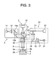
- Fig. 3 is a diagram showing a whole construction of a microscope equipped with a focus detection apparatus according to a second embodiment of the present invention.
- a microscope equipped with a focus detection apparatus according to the present embodiment or the third embodiment of the present invention is explained below, in which a construction same as the first embodiment is attached the same symbol with omitting the explanation thereof, and a construction different from the first embodiment is attached different symbol with explaining in detail.
- a focus detection apparatus 30 according to the present embodiment is equipped with an IR light source 31 capable of selectively emanating light with a plurality of wavelengths as shown in Fig. 4A instead of the IR light source 16 in the focus detection apparatus according to the first embodiment, and a dichroic mirror unit 32 as shown in Fig. 4B instead of the dichroic mirror 15.
- Fig. 4A is a diagram showing a configuration of an IR light source 31 of the focus detection apparatus 30 according to the second embodiment of the present invention.
- the dichroic mirror unit 32 is equipped with a dichroic mirror 32a that reflects only near-infrared light with the wavelength ⁇ IR1 , a dichroic mirror 32b that reflects only infrared light with the wavelength ⁇ IR2 as shown in Fig. 5 , and a dichroic mirror 32c that reflects only infrared light with the wavelength ⁇ IR3 .
- Fig. 4B is a diagram showing a configuration of a dichroic mirror unit 32 of the focus detection apparatus 30 according to the second embodiment of the present invention.
- Fig. 5 is a graph showing reflection characteristic of a dichroic mirror 32b of the dichroic mirror unit 32.
- the dichroic mirror unit 32 is equipped with a slide mechanism (not shown). Accordingly, by sliding the dichroic mirror unit 32 through the slide mechanism, each of the dichroic mirrors 32a, 32b, and 32c can be selectively disposed in the optical path. As a result, a dichroic mirror corresponding to a wavelength of an LED selected in the IR light source 31 can be disposed in the optical path.
- near-infrared light with the wavelength ⁇ IR1 emanated from the LED 31a in the IR light source 31 passes through the lens 17, the half mask 18 and the semi-transparent mirror 19, and reflected by the dichroic mirror 32a of the dichroic mirror unit 32 to the sample 6 side.
- the light After passing through the objective lens 8, the light is reflected by the glass interface 6a.
- the reflected near-infrared light with the wavelength ⁇ IR1 is reflected again by the dichroic mirror 32a of the dichroic mirror unit 32, reflected again by the semi-transparent mirror 19, and forms an image on the detecting surface of the photodetector 21 through the imaging lens 20.
- Focusing movement and keeping thereof performed in the controller 22 installed in the focus detection apparatus 30 is the same as the above-described first embodiment.
- the microscope can carry out the similar effect as the first embodiment.
- the microscope can change the wavelength range of the focus detection light corresponding to the observation method to be used together with the ordinary observation by changing LED 31a, 31b, or 31c, and corresponding dichroic mirror 32a, 32b, or 32c in the focus detection apparatus 30.
- the dichroic mirror 32b is disposed on the optical path to make LED 31b radiate, in other words, when infrared light with the wavelength ⁇ IR2 is used as focus detection light, it becomes possible to carry out a fluorescence observation using a long wavelength fluorescent dye (wavelength ⁇ FL4 ) and an optical tweezers observation (wavelength ⁇ IR3 ) in addition to an ordinary observation (wavelengths ⁇ FL1 , ⁇ FL2 , ⁇ FL3 ) as shown in Fig. 5 . Even if the wavelength range of the focus detection light is changed, signal detection condition of the photodetector is made to change electrically, so that focusing state of the sample can be secured.
- Fig. 6 is a diagram showing a whole construction of a microscope equipped with a focus detection apparatus according to a third embodiment of the present invention.
- the focus detection apparatus 40 according to the present embodiment is equipped with a partial mirror 41 as shown in Fig. 7 instead of the dichroic mirror 15 in the focus detection apparatus 3 according to the first embodiment.
- Figs. 7A and 7B are diagrams showing a configuration of a partial mirror 41 of the focus detection apparatus 40 according to the third embodiment of the present invention, in which Fig. 7A shows a top view, and Fig. 7B shows a front view.
- the partial mirror 41 is composed of a partial mirror body 42, and two triangular prisms 43a and 43b that hold the partial mirror body in between.
- the partial mirror body 42 is composed of a transparent surface 42a that has an elliptical shape whose major axis extends in an optical axis direction of the objective lens 8 in the microscope body 2 seen from the IR light source 16 side, and a reflecting surface 42b that is provided at each end portion of the major axis of the transparent surface 42a.
- the transparent surface 42a of the partial mirror 42 is made sufficiently large so as not to block the light from the sample 6 illuminated by the illumination light source (not shown) in the microscope body 2 and the laser light from the optical tweezers optical system 4, the partial mirror 41 does not cause trouble upon ordinary observation or optical tweezers observation. Even if it blocks light, the amount of blocked light is small, so that it is acceptable.
- the light emanated from the IR light source 16 with a given wavelength range passes through the lens 17, the half mask 18, the semi-transparent mirror 19 in this order, and is reflected by the reflecting surface 42b to the sample 6 side.
- the light After passing through the objective lens 8, the light is reflected by the glass interface 6a disposed in the vicinity of the sample 6.
- the reflected light from the glass interface 6a is reflected again by the reflecting surface 42b of the partial mirror 41, reflected again by the semi-transparent mirror 19 to form an image on the detecting surface of the photodetector 21 through the imaging lens 20.
- Focusing movement and keeping thereof performed in the controller 22 installed in the focus detection apparatus 40 is the same as the above-described first embodiment.
- the microscope can carry out the same effect as the first embodiment.
- the focus detection apparatus 40 according to the present embodiment may be equipped with the IR light source 31 according to the second embodiment instead of the IR light source 16. With this configuration, it becomes possible to carry out the same effect as the second embodiment. Since the partial mirror 41 can be used regardless of the wavelength range of the focus detection light, and the work that the dichroic mirror unit 32 is moved into the optical path in the second embodiment is not necessary, it becomes possible to realize a smooth exchange of the focus detection light.
- each embodiment it becomes possible to realize a focus detection apparatus that limits a wavelength range of light used for the focus detection and makes it possible to use light with wavelength range except the wavelength of focus detection for microscope observation such as an ordinary observation and an applied technology accompanied by this, and a microscope equipped therewith.
Abstract
Description
- The present invention relates to a focus detection apparatus and a microscope.
- There have been proposed focus detection apparatuses for a biological microscope such as a technique that keeps focusing by detecting a glass interface in the vicinity of a sample using reflection of infrared light (for example, see Japanese Patent Application Laid-Open No.
2004-070276 - However, in a recent biological microscope, wavelength of a fluorescent dye used upon fluorescence observation has been getting longer, and such an observation using optical tweezers or two-photon excitation has been adopted. Accordingly, in a biological microscope, the wavelength of observation light is not limited to visible light, so that light having a wavelength range of near-infrared cannot be exclusively used for focus detection and keeping thereof.
- The present invention is made in view of the aforementioned problems, and has an object to provide a focus detection apparatus that limits a wavelength range of light used for the focus detection and uses broader wavelength range except the wavelength of focus detection for microscope observation and other purposes than the focus detection, and a microscope equipped therewith.
- In order to solve the above-described problems, according to a first aspect of the present invention, there is provided a focus detection apparatus comprising: a light source that emanates light with a given wavelength range; and an optical member that reflects focus detection light with a given wavelength range in order to detect focus shift between an objective lens and an object to be observed in a microscope, and transmits non-focus detection light with at least two wavelength ranges except the given wavelength range.
- In the first aspect of the present invention, it is preferable that the wavelength range of the light that is emanated from the light source and reflected by the optical member is located between two wavelength ranges of light that comes from the object to be observed and transmits the optical member.
- In the first aspect of the present invention, it is preferable that the optical member is a partial mirror that reflects marginal light flux of the light with the given wavelength range to lead to the object to be observed, and transmits the rest of the light flux.
- In the first aspect of the present invention, it is preferable that the light source selectively emanates light with a plurality of different wavelength ranges, and the optical member is a dichroic mirror unit equipped with a plurality of dichroic mirrors that are corresponding to the light with the plurality of different wavelength ranges emanated from the light source, and removably movable into an optical path.
- In the first aspect of the present invention, it is preferable that the light source selectively emanates light with a plurality of different wavelength ranges.
- In the first aspect of the present invention, the focus detection apparatus preferably further comprising the light source that emanates light with a given wavelength range for illuminating the object to be observed for focus detection.
- In the first aspect of the present invention, the focus detection apparatus preferably further comprises a photodetector that detects reflected light of the light source reflected by the object to be observed.
- In the first aspect of the present invention, the focus detection apparatus preferably further comprises a controller that detects focus shift between the objective lens and the object to be observed in the microscope on the basis of a signal from the photodetector.
- In the first aspect of the present invention, the focus detection apparatus preferably further comprises a second light source that emanates the non-focus detection light.
- In the first aspect of the present invention, the focus detection apparatus preferably further comprises a second optical member that reflects light emanated from the second light source to the object to be observed and transmits light from the object to be observed.
- In the first aspect of the present invention, it is preferable that the first light source emanates light with an infrared wavelength range, and the second light source emanates light with a longer wavelength range than the infrared wavelength range.
- According to a second aspect of the present invention, there is provided a microscope equipped with the focus detection apparatus according to the first aspect.
- In the second aspect of the present invention, it is preferable that the microscope includes an objective lens and a camera attaching portion, the optical member and the second optical member are disposed on the optical path between the objective lens and the camera attaching portion, the optical member is disposed to the objective lens side, and the second optical member is disposed to the camera attaching portion side.
- In the second aspect of the present invention, it is preferable that the second light source is a light source of an optical tweezers.
- In the second aspect of the present invention, it is preferable that the second light source is a light source of a two-photon excitation.
- In the second aspect of the present invention, it is preferable that the first light source emanates light with an infrared wavelength range, and the second light source emanates light with a longer wavelength range than the infrared wavelength range.
- The present invention makes it possible to provide a focus detection apparatus that limits a wavelength range of light used for the focus detection and uses broader wavelength range except the wavelength of focus detection for microscope observation and other purposes than the focus detection, and a microscope equipped therewith.
-
-
Fig. 1 is a diagram showing a whole construction of a microscope equipped with a focus detection apparatus according to a fist embodiment of the present invention. -
Fig. 2 is a graphs showing reflection characteristic of adichroic mirror 15 of thefocus detection apparatus 3 according to the first embodiment of the present invention. -
Fig. 3 is a diagram showing a whole construction of a microscope equipped with a focus detection apparatus according to a second embodiment of the present invention. -
Figs. 4A and 4B are diagrams showing a configuration of thefocus detection apparatus 30 according to the second embodiment of the present invention, in whichFig. 4A shows a configuration of anIR light source 31, andFig. 4B shows a configuration of adichroic mirror unit 32. -
Fig. 5 is a graph showing reflection characteristic of adichroic mirror 32b of thedichroic mirror unit 32. -
Fig. 6 is a diagram showing a whole construction of a microscope equipped with a focus detection apparatus according to a third embodiment of the present invention. -
Figs. 7A and 7B are diagrams showing a configuration of apartial mirror 41 of thefocus detection apparatus 40 according to the third embodiment of the present invention, in whichFig. 7A shows a top view, andFig. 7B shows a front view. - A microscope equipped with a focus detection apparatus according to each embodiment of the present invention is explained below with reference to accompanying drawings.
- At first, an overall construction of a microscope equipped with a focus detection apparatus according to the present embodiment.
-
Fig. 1 is a diagram showing a whole construction of a microscope equipped with a focus detection apparatus according to a first embodiment of the present invention. - As shown in
Fig. 1 , the microscope 1 is composed of amicroscope body 2, afocus detection apparatus 3, and an optical tweezersoptical system 4. - In the present embodiment, light except the light using for focus detection is called non-defocus-detection light. In this non-defocus-detection light, there are optical-tweezers light, multi-photon-excitation light, and, for example, fluorescence light from an object to be observed in the fluorescence observation. A light source emanating optical-tweezers light and multi-photon-excitation light is called as a second light source.
- The
microscope body 2 is equipped with astage 7 on which asample 6 put between acover glass 5a and aslide glass 5b is placed, and in order from thestage 7 side, anobjective lens 8, animaging lens 9, and acamera 10. On the other side of thestage 7 viewed from theobjective lens 8 side, there is provided an illumination light source (not shown) that emanates illumination light for illuminating thesample 6 including the wavelength λFL1, λFL2, λFL3 which are shorter than a wavelength λIR1 of near-infrared light explained later. Theobjective lens 8 is electrically movable in a direction up and down by an objective lens driver (not shown). - The optical tweezers
optical system 4 is equipped with alaser light source 11, and in order from thelaser light source 11 side, alens 12,mirrors semi-transparent mirror 14. Thesemi-transparent mirror 14 is disposed on an optical path between theobjective lens 8 and theimaging lens 9 in themicroscope body 2, so that laser light emanated from thelaser light source 11 can be led to the optical path in themicroscope body 2 to illuminate thesample 6. In the present embodiment, thelaser light source 11 emanates infrared laser light with a wavelength λIR3=1064 nm. - With the above-described configuration, in the
microscope body 2, light from thesample 6 illuminated by an illumination light source (not shown) passes through theobjective lens 8, adichroic mirror 15 explained later, and thesemi-transparent mirror 14 in this order, and forms an image on an imaging surface of thecamera 10 by theimaging lens 9. Accordingly, thecamera 10 can take an image of thesample 6, and an observer can observe the taken image of thesample 6 through a monitor (not shown) (hereinafter called as "ordinary observation"). - In the optical tweezers
optical system 4, laser light emanated from thelaser light source 11 is reflected by themirrors lens 12, led to thesemi-transparent mirror 14 in themicroscope body 2. The laser light is reflected by thesemi-transparent mirror 14, and after passing through thedichroic mirror 15 explained later illuminates thesample 6 through theobjective lens 8. Accordingly, the observer can carry out the optical tweezers operation to the sample 6 (hereinafter called as "optical tweezers observation"). - Then, configuration of the
focus detection apparatus 3 that is the most characteristic feature of the present embodiment is explained in detail. - The
focus detection apparatus 3 is equipped with anIR light source 16 that emanates light with a given wavelength range and, in order from theIR light source 16 side, alens 17, a half-mask 18, asemi-transparent mirror 19, and thedichroic mirror 15, and on the reflection optical path of thesemi-transparent mirror 19, there are provided with animaging lens 20, and aphotodetector 21. In the present embodiment, the light with the given wavelength emanated from theIR light source 16 is near-infrared light with the wavelength λIR1=770 nm. - The
dichroic mirror 15 is disposed on the optical path between theobjective lens 8 and thesemi-transparent mirror 14 in themicroscope body 2, so that thedichroic mirror 15 can lead the light from theIR light source 16 to the optical path of themicroscope body 2. As shown inFig. 2 , thedichroic mirror 15 according to the present embodiment has a characteristic that reflects only certain light emanated from theIR light source 16 with a given wavelength range, in other words, only near-infrared light with the wavelength λIR1.Fig. 2 is a graphs showing reflection characteristic of adichroic mirror 15 of thefocus detection apparatus 3 according to the first embodiment of the present invention. - With the above-described configuration, in the
focus detection apparatus 3, light emanated from the IRlight source 16 with a given wavelength range passes through thelens 17, thehalf mask 18, and thesemi-transparent mirror 19 in this order, and is reflected by thedichroic mirror 15 to thesample 6 side. After passing through theobjective lens 8, the light is reflected by aglass interface 6a in the vicinity of thesample 6. The reflected light of the IRlight source 16 reflected by theglass interface 6a is reflected again by thedichroic mirror 15 in the IRlight source 16 direction, and after reflected by thesemi-transparent mirror 19 forms an image on a detecting surface of thephotodetector 21 through theimaging lens 20. - As a result, a
controller 22 installed in thefocus detection apparatus 3 detects the position in the optical axis direction of theglass interface 6a on the basis of the detected signal of thephotodetector 21, in other words, defocus between theobjective lens 8 and theglass interface 6a is detected, and theobjective lens 8 is driven by the objective driver (not shown) installed in themicroscope body 2, so that theglass interface 6a is disposed on the focus position of theobjective lens 8. Accordingly, focusing on thesample 6 is accomplished in themicroscope body 2. Since the above-described focusing operation is always carried out upon observation, the state of focusing on thesample 6 is kept upon observation. Accordingly, the present microscope 1 is extremely useful upon performing an observation together with a dosage or a long time observation, or a continuous observation of a plurality of positions of a sample. - As described above, in the microscope 1, with limiting the light using for the focus detection apparatus 3 (hereinafter called as "focus detection light") to a given wavelength range, light having longer wavelength than the focus detection light can be used for observation. Accordingly, the microscope 1 can perform the optical tweezers observation using the light with longer wavelength than the focus detection light in addition to the ordinal observation using the light with shorter than the focus detection light.
- As described above, although the microscope 1 is equipped with the optical tweezers
optical system 4, the present invention is not limited to this, and may include an optical system for performing a two-photon excitation observation having a light source emanating infrared light of the wavelength λIR2=850 nm through 1000 nm instead of the optical tweezersoptical system 4. In this case, the microscope 1 can perform two-photon excitation observation using the light having longer wavelength than the focus detection light in addition to ordinary observation of thesample 6. - Moreover, focus movement of the present embodiment is carried out by disposing the
glass interface 6a to the focus position of theobjective lens 8 as described above. However, the configuration of the present embodiment is not limited to this, and the focus detection apparatus preferably includes an offset lens movably in the optical axis direction disposed on the optical path between thesemi-transparent mirror 19 and thedichroic mirror 15. By moving the offset lens, theglass interface 6a can be disposed with shifting a given offset amount along the optical axis upon setting theglass interface 6a to the focus position of theobjective lens 8. Accordingly, not only theglass interface 6a in other words the surface of thesample 6, but also any position in the depth direction can be focused. Such an offset lens is preferably installed in a focus detection apparatus according to each of the following embodiments. - As described above in the present embodiment, although focusing movement is carried out by moving the
objective lens 8 in a direction up and down by the objective lens driver (not shown), the present embodiment is not limited to this, and may provide a stage driver, so that focusing movement is carried out by moving thestage 7 in a direction up and down. This is the same in a microscope according to each of the following embodiments. -
Fig. 3 is a diagram showing a whole construction of a microscope equipped with a focus detection apparatus according to a second embodiment of the present invention. - A microscope equipped with a focus detection apparatus according to the present embodiment or the third embodiment of the present invention is explained below, in which a construction same as the first embodiment is attached the same symbol with omitting the explanation thereof, and a construction different from the first embodiment is attached different symbol with explaining in detail.
- A
focus detection apparatus 30 according to the present embodiment is equipped with an IRlight source 31 capable of selectively emanating light with a plurality of wavelengths as shown inFig. 4A instead of the IRlight source 16 in the focus detection apparatus according to the first embodiment, and adichroic mirror unit 32 as shown inFig. 4B instead of thedichroic mirror 15. - In the present embodiment, the IR
light source 31 is equipped with anLED 31a emanating near-infrared light with a wavelength λIR1=770 nm, anLED 31b emanating infrared light with a wavelength λIR2=870 nm, and anLED 31c emanating infrared light with a wavelength λIR3=1064 nm, and an observer can selectively activate these LEDs.Fig. 4A is a diagram showing a configuration of an IRlight source 31 of thefocus detection apparatus 30 according to the second embodiment of the present invention. - The
dichroic mirror unit 32 is equipped with adichroic mirror 32a that reflects only near-infrared light with the wavelength λIR1, adichroic mirror 32b that reflects only infrared light with the wavelength λIR2 as shown inFig. 5 , and adichroic mirror 32c that reflects only infrared light with the wavelength λIR3.Fig. 4B is a diagram showing a configuration of adichroic mirror unit 32 of thefocus detection apparatus 30 according to the second embodiment of the present invention.Fig. 5 is a graph showing reflection characteristic of adichroic mirror 32b of thedichroic mirror unit 32. - The
dichroic mirror unit 32 is equipped with a slide mechanism (not shown). Accordingly, by sliding thedichroic mirror unit 32 through the slide mechanism, each of thedichroic mirrors light source 31 can be disposed in the optical path. - With this configuration, in the
focus detection apparatus 30, near-infrared light with the wavelength λIR1 emanated from theLED 31a in the IRlight source 31 passes through thelens 17, thehalf mask 18 and thesemi-transparent mirror 19, and reflected by thedichroic mirror 32a of thedichroic mirror unit 32 to thesample 6 side. After passing through theobjective lens 8, the light is reflected by theglass interface 6a. The reflected near-infrared light with the wavelength λIR1 is reflected again by thedichroic mirror 32a of thedichroic mirror unit 32, reflected again by thesemi-transparent mirror 19, and forms an image on the detecting surface of thephotodetector 21 through theimaging lens 20. - Focusing movement and keeping thereof performed in the
controller 22 installed in thefocus detection apparatus 30 is the same as the above-described first embodiment. - Although the above-described explanation is made for near-infrared light with the wavelength λIR1 emanated from the
LED 31a, the similar focusing movement and keeping thereof can be accomplished regarding infrared light with the wavelength λIR2 emanated from theLED 31b or infrared light with the wavelength λIR3 emanated from theLED 31c by disposing correspondingdichroic mirror dichroic mirror unit 32 into the optical path - As described above, the microscope can carry out the similar effect as the first embodiment.
- As described above, the microscope can change the wavelength range of the focus detection light corresponding to the observation method to be used together with the ordinary observation by changing
LED dichroic mirror focus detection apparatus 30. Specifically, for example, thedichroic mirror 32b is disposed on the optical path to makeLED 31b radiate, in other words, when infrared light with the wavelength λIR2 is used as focus detection light, it becomes possible to carry out a fluorescence observation using a long wavelength fluorescent dye (wavelength λFL4) and an optical tweezers observation (wavelength λIR3) in addition to an ordinary observation (wavelengths λFL1, λFL2, λFL3) as shown inFig. 5 . Even if the wavelength range of the focus detection light is changed, signal detection condition of the photodetector is made to change electrically, so that focusing state of the sample can be secured. -
Fig. 6 is a diagram showing a whole construction of a microscope equipped with a focus detection apparatus according to a third embodiment of the present invention. - The
focus detection apparatus 40 according to the present embodiment is equipped with apartial mirror 41 as shown inFig. 7 instead of thedichroic mirror 15 in thefocus detection apparatus 3 according to the first embodiment. -
Figs. 7A and 7B are diagrams showing a configuration of apartial mirror 41 of thefocus detection apparatus 40 according to the third embodiment of the present invention, in whichFig. 7A shows a top view, andFig. 7B shows a front view. - As shown in
Fig. 7B , thepartial mirror 41 is composed of apartial mirror body 42, and twotriangular prisms Fig. 7B , thepartial mirror body 42 is composed of atransparent surface 42a that has an elliptical shape whose major axis extends in an optical axis direction of theobjective lens 8 in themicroscope body 2 seen from the IRlight source 16 side, and a reflectingsurface 42b that is provided at each end portion of the major axis of thetransparent surface 42a. - With this configuration of the
partial mirror 42, most of near-infrared light from the IRlight source 16 is transmitted to be disposed outside of the optical path, and only marginal light flux proceeding high NA area is reflected to theglass interface 6a side, and the marginal light flux reflected from theglass interface 6a can be reflected again to thesemi-transparent mirror 19 side. - Since the
transparent surface 42a of thepartial mirror 42 is made sufficiently large so as not to block the light from thesample 6 illuminated by the illumination light source (not shown) in themicroscope body 2 and the laser light from the optical tweezersoptical system 4, thepartial mirror 41 does not cause trouble upon ordinary observation or optical tweezers observation. Even if it blocks light, the amount of blocked light is small, so that it is acceptable. - With this configuration, in the
focus detection apparatus 40, the light emanated from the IRlight source 16 with a given wavelength range (near-infrared light with a wavelength λIR1) passes through thelens 17, thehalf mask 18, thesemi-transparent mirror 19 in this order, and is reflected by the reflectingsurface 42b to thesample 6 side. After passing through theobjective lens 8, the light is reflected by theglass interface 6a disposed in the vicinity of thesample 6. The reflected light from theglass interface 6a is reflected again by the reflectingsurface 42b of thepartial mirror 41, reflected again by thesemi-transparent mirror 19 to form an image on the detecting surface of thephotodetector 21 through theimaging lens 20. - Focusing movement and keeping thereof performed in the
controller 22 installed in thefocus detection apparatus 40 is the same as the above-described first embodiment. - As described above, the microscope can carry out the same effect as the first embodiment.
- The
focus detection apparatus 40 according to the present embodiment may be equipped with the IRlight source 31 according to the second embodiment instead of the IRlight source 16. With this configuration, it becomes possible to carry out the same effect as the second embodiment. Since thepartial mirror 41 can be used regardless of the wavelength range of the focus detection light, and the work that thedichroic mirror unit 32 is moved into the optical path in the second embodiment is not necessary, it becomes possible to realize a smooth exchange of the focus detection light. - According to each embodiment, it becomes possible to realize a focus detection apparatus that limits a wavelength range of light used for the focus detection and makes it possible to use light with wavelength range except the wavelength of focus detection for microscope observation such as an ordinary observation and an applied technology accompanied by this, and a microscope equipped therewith.
Claims (16)
- A focus detection apparatus comprising:a light source that emanates light with a given wavelength range; andan optical member that reflects focus detection light with a given wavelength range in order to detect focus shift between an objective lens and an object to be observed in a microscope, and transmits non-focus detection light with at least two wavelength ranges other than the given wavelength range.
- The focus detection apparatus according to claim 1, wherein the wavelength range of the light that is emanated from the light source and reflected by the optical member is located between two wavelength ranges of light that comes from the object to be observed and is transmitted by the optical member.
- The focus detection apparatus according to claim 1, wherein the optical member is a partial mirror that reflects marginal light flux of the light with the given wavelength range to lead to the object to be observed, and transmits the rest of the light flux.
- The focus detection apparatus according to claim 1, wherein the light source selectively emanates light with a plurality of different wavelength ranges, and the optical member is a dichroic mirror unit equipped with a plurality of dichroic mirrors that are corresponding to the light with the plurality of different wavelength ranges emanated from the light source, and removably movable into an optical path.
- The focus detection apparatus according to claim 3, wherein the light source selectively emanates light with a plurality of different wavelength ranges.
- The focus detection apparatus according to claim 1, further comprising the light source that emanates light with a given wavelength range for illuminating the object to be observed for focus detection.
- The focus detection apparatus according to claim 6, further comprising a photodetector that detects reflected light of the light source reflected by the object to be observed.
- The focus detection apparatus according to claim 7, further comprising a controller that detects focus shift between the objective lens and the object to be observed in the microscope on the basis of a signal from the photodetector.
- The focus detection apparatus according to claim 1, further comprising a second light source that emanates the non-focus detection light.
- The focus detection apparatus according to claim 9, further comprising a second optical member that reflects light emanated from the second light source to the object to be observed and transmits light from the object to be observed.
- The focus detection apparatus according to claim 9, wherein the first light source emanates light with an infrared wavelength range, and the second light source emanates light with a longer wavelength range than the infrared wavelength range.
- A microscope equipped with the focus detection apparatus according to any one of claims 1 through 11.
- The microscope according to claim 12, wherein the microscope includes an objective lens and a camera attaching portion, the optical member and the second optical member are disposed on the optical path between the objective lens and the camera attaching portion, the optical member is disposed to the objective lens side, and the second optical member is disposed to the camera attaching portion side.
- The microscope according to claim 12, wherein the second light source is a light source of an optical tweezers.
- The microscope according to claim 12, wherein the second light source is a light source of a two-photon excitation.
- The microscope according to claim 12, wherein the first light source emanates light with an infrared wavelength range, and the second light source emanates light with a longer wavelength range than the infrared wavelength range.
Applications Claiming Priority (2)
| Application Number | Priority Date | Filing Date | Title |
|---|---|---|---|
| JP2007010541 | 2007-01-19 | ||
| PCT/JP2008/050463 WO2008087992A1 (en) | 2007-01-19 | 2008-01-09 | Focal point detecting apparatus and microscope |
Publications (2)
| Publication Number | Publication Date |
|---|---|
| EP2107406A1 true EP2107406A1 (en) | 2009-10-07 |
| EP2107406A4 EP2107406A4 (en) | 2012-02-01 |
Family
ID=39635994
Family Applications (1)
| Application Number | Title | Priority Date | Filing Date |
|---|---|---|---|
| EP08703323A Ceased EP2107406A4 (en) | 2007-01-19 | 2008-01-09 | Focal point detecting apparatus and microscope |
Country Status (5)
| Country | Link |
|---|---|
| US (1) | US8208202B2 (en) |
| EP (1) | EP2107406A4 (en) |
| JP (1) | JP5463671B2 (en) |
| CN (1) | CN101583895B (en) |
| WO (1) | WO2008087992A1 (en) |
Cited By (2)
| Publication number | Priority date | Publication date | Assignee | Title |
|---|---|---|---|---|
| WO2012097191A3 (en) * | 2011-01-12 | 2013-01-03 | Idea Machine Development Design & Production Ltd. | Compact microscopy system and method |
| WO2015157520A1 (en) * | 2014-04-10 | 2015-10-15 | Thorlabs, Inc. | Autofocus system |
Families Citing this family (4)
| Publication number | Priority date | Publication date | Assignee | Title |
|---|---|---|---|---|
| JP6153321B2 (en) * | 2012-12-10 | 2017-06-28 | オリンパス株式会社 | microscope |
| JP6171824B2 (en) * | 2013-10-10 | 2017-08-02 | セイコーエプソン株式会社 | Method for manufacturing liquid jet head |
| WO2017090210A1 (en) * | 2015-11-27 | 2017-06-01 | 株式会社ニコン | Microscope, observation method, and image processing program |
| DE102016119727A1 (en) * | 2016-10-17 | 2018-04-19 | Carl Zeiss Microscopy Gmbh | Device for beam manipulation for a scanning microscope and microscope |
Citations (4)
| Publication number | Priority date | Publication date | Assignee | Title |
|---|---|---|---|---|
| WO2000037984A2 (en) * | 1998-12-21 | 2000-06-29 | Evotec Biosystems Ag | Positioning of the measuring volume in a scanning microscopic method |
| US20040113043A1 (en) * | 2002-06-14 | 2004-06-17 | Nikon Corporation | Autofocus system and microscope |
| US20050175233A1 (en) * | 2002-12-26 | 2005-08-11 | Olympus Corporation | Defect inspection apparatus and defect inspection method |
| WO2006024967A1 (en) * | 2004-09-02 | 2006-03-09 | 3D Histech Kft. | Focusing method for the high-speed digitalisation of microscope slides and slide displacing device, focusing optics, and optical rangefinder |
Family Cites Families (17)
| Publication number | Priority date | Publication date | Assignee | Title |
|---|---|---|---|---|
| JPS6173132A (en) * | 1984-09-18 | 1986-04-15 | Minolta Camera Co Ltd | Camera system for executing automatic focus adjustment using auxiliary light |
| DE3828381C2 (en) * | 1988-08-20 | 1997-09-11 | Zeiss Carl Fa | Method and device for automatically focusing an optical system |
| US5537168A (en) * | 1991-04-26 | 1996-07-16 | Canon Kabushiki Kaisha | Projection optical apparatus comprising automatic adjustment unit |
| JPH1020198A (en) * | 1996-07-02 | 1998-01-23 | Olympus Optical Co Ltd | Near infrared microscope and microscope observation system using the same |
| US6226118B1 (en) * | 1997-06-18 | 2001-05-01 | Olympus Optical Co., Ltd. | Optical microscope |
| JP4962749B2 (en) * | 2001-04-09 | 2012-06-27 | 株式会社ニコン | Light particle handling equipment |
| US6603607B2 (en) | 2000-04-07 | 2003-08-05 | Nikon Corporation | Minute particle optical manipulation method and apparatus |
| DE10035190C5 (en) | 2000-07-20 | 2009-07-16 | MAX-PLANCK-Gesellschaft zur Förderung der Wissenschaften e.V. | Method and device for fluorescence measurement |
| JP4021183B2 (en) * | 2001-11-29 | 2007-12-12 | オリンパス株式会社 | Focus state signal output device |
| IL148664A0 (en) * | 2002-03-13 | 2002-09-12 | Yeda Res & Dev | Auto-focusing method and device |
| JP2003270524A (en) * | 2002-03-19 | 2003-09-25 | Nikon Corp | Focus detector and microscope provided therewith, and method for detecting focus |
| CN2550755Y (en) * | 2002-07-03 | 2003-05-14 | 中国科学技术大学 | Micro diagnostic device for disperse system stable degree |
| JP2005062515A (en) * | 2003-08-13 | 2005-03-10 | Nikon Corp | Fluorescence microscope |
| JP4932162B2 (en) * | 2005-01-20 | 2012-05-16 | オリンパス株式会社 | Focus detection device and fluorescence observation device using the same |
| JP2006276193A (en) * | 2005-03-28 | 2006-10-12 | Nikon Corp | Microscope |
| JP2006309088A (en) * | 2005-05-02 | 2006-11-09 | Research Organization Of Information & Systems | Highly precise measurement method of microscope focusing position |
| JP4428370B2 (en) * | 2006-09-19 | 2010-03-10 | 株式会社ニコン | Confocal microscope |
-
2008
- 2008-01-09 WO PCT/JP2008/050463 patent/WO2008087992A1/en active Application Filing
- 2008-01-09 JP JP2008554066A patent/JP5463671B2/en active Active
- 2008-01-09 CN CN2008800021034A patent/CN101583895B/en active Active
- 2008-01-09 EP EP08703323A patent/EP2107406A4/en not_active Ceased
-
2009
- 2009-07-09 US US12/500,202 patent/US8208202B2/en active Active
Patent Citations (4)
| Publication number | Priority date | Publication date | Assignee | Title |
|---|---|---|---|---|
| WO2000037984A2 (en) * | 1998-12-21 | 2000-06-29 | Evotec Biosystems Ag | Positioning of the measuring volume in a scanning microscopic method |
| US20040113043A1 (en) * | 2002-06-14 | 2004-06-17 | Nikon Corporation | Autofocus system and microscope |
| US20050175233A1 (en) * | 2002-12-26 | 2005-08-11 | Olympus Corporation | Defect inspection apparatus and defect inspection method |
| WO2006024967A1 (en) * | 2004-09-02 | 2006-03-09 | 3D Histech Kft. | Focusing method for the high-speed digitalisation of microscope slides and slide displacing device, focusing optics, and optical rangefinder |
Non-Patent Citations (1)
| Title |
|---|
| See also references of WO2008087992A1 * |
Cited By (5)
| Publication number | Priority date | Publication date | Assignee | Title |
|---|---|---|---|---|
| WO2012097191A3 (en) * | 2011-01-12 | 2013-01-03 | Idea Machine Development Design & Production Ltd. | Compact microscopy system and method |
| GB2497700A (en) * | 2011-01-12 | 2013-06-19 | Idea Machine Dev Design & Production Ltd | Compact microscopy system and method |
| US9170412B2 (en) | 2011-01-12 | 2015-10-27 | Idea Machines Development Design & Production Ltd. | Objective lens changer mechanism suitable for use in a compact microscopy system |
| WO2015157520A1 (en) * | 2014-04-10 | 2015-10-15 | Thorlabs, Inc. | Autofocus system |
| US9488820B2 (en) | 2014-04-10 | 2016-11-08 | Thorlabs, Inc. | Autofocus system |
Also Published As
| Publication number | Publication date |
|---|---|
| EP2107406A4 (en) | 2012-02-01 |
| US8208202B2 (en) | 2012-06-26 |
| WO2008087992A1 (en) | 2008-07-24 |
| CN101583895B (en) | 2012-09-05 |
| JP5463671B2 (en) | 2014-04-09 |
| US20090273830A1 (en) | 2009-11-05 |
| JPWO2008087992A1 (en) | 2010-05-06 |
| CN101583895A (en) | 2009-11-18 |
Similar Documents
| Publication | Publication Date | Title |
|---|---|---|
| JP4546741B2 (en) | Fluorescence microscope | |
| US20190258040A1 (en) | Laser scan confocal microscope | |
| US8098279B2 (en) | Imaging apparatus and microscope | |
| JP5006694B2 (en) | Lighting device | |
| US8014065B2 (en) | Microscope apparatus with fluorescence cube for total-internal-reflection fluorescence microscopy | |
| US8208202B2 (en) | Focus detection apparatus, microscope | |
| EP2315065A2 (en) | Microscope | |
| JP2006201465A5 (en) | ||
| JP4854880B2 (en) | Laser microscope | |
| JP2003195181A (en) | Fixed high magnification changeover type microscope | |
| JP2003270524A (en) | Focus detector and microscope provided therewith, and method for detecting focus | |
| WO2009142312A1 (en) | Microscope apparatus | |
| JP4128387B2 (en) | Microscope equipment | |
| US6906312B2 (en) | Scanning microscope having a microscope stand | |
| JP5437052B2 (en) | Microscope equipment | |
| US20050078362A1 (en) | Microscope | |
| JP4643182B2 (en) | Total reflection microscope | |
| JP5307868B2 (en) | Total reflection microscope | |
| JP2004185005A (en) | Transmitted light illumination unit of microscope | |
| JP3845164B2 (en) | Automatic focus adjustment method and apparatus | |
| JP4713391B2 (en) | Infrared microscope | |
| JP3115100U (en) | microscope | |
| JP2006171027A (en) | Illuminating device for microscope and fluorescence microscope system | |
| JP4686015B2 (en) | Lighting device | |
| JP5109583B2 (en) | Inverted microscope |
Legal Events
| Date | Code | Title | Description |
|---|---|---|---|
| PUAI | Public reference made under article 153(3) epc to a published international application that has entered the european phase |
Free format text: ORIGINAL CODE: 0009012 |
|
| 17P | Request for examination filed |
Effective date: 20090817 |
|
| AK | Designated contracting states |
Kind code of ref document: A1 Designated state(s): AT BE BG CH CY CZ DE DK EE ES FI FR GB GR HR HU IE IS IT LI LT LU LV MC MT NL NO PL PT RO SE SI SK TR |
|
| DAX | Request for extension of the european patent (deleted) | ||
| RAP1 | Party data changed (applicant data changed or rights of an application transferred) |
Owner name: NIKON CORPORATION |
|
| A4 | Supplementary search report drawn up and despatched |
Effective date: 20111230 |
|
| RIC1 | Information provided on ipc code assigned before grant |
Ipc: G02B 21/00 20060101ALI20111223BHEP Ipc: G02B 21/24 20060101ALI20111223BHEP Ipc: G02B 21/32 20060101ALI20111223BHEP Ipc: G02B 21/06 20060101ALI20111223BHEP Ipc: G02B 7/28 20060101AFI20111223BHEP |
|
| 17Q | First examination report despatched |
Effective date: 20120822 |
|
| APBK | Appeal reference recorded |
Free format text: ORIGINAL CODE: EPIDOSNREFNE |
|
| APBN | Date of receipt of notice of appeal recorded |
Free format text: ORIGINAL CODE: EPIDOSNNOA2E |
|
| REG | Reference to a national code |
Ref country code: DE Ref legal event code: R003 |
|
| APAF | Appeal reference modified |
Free format text: ORIGINAL CODE: EPIDOSCREFNE |
|
| APBT | Appeal procedure closed |
Free format text: ORIGINAL CODE: EPIDOSNNOA9E |
|
| STAA | Information on the status of an ep patent application or granted ep patent |
Free format text: STATUS: THE APPLICATION HAS BEEN REFUSED |
|
| 18R | Application refused |
Effective date: 20140820 |