JP4128387B2 - Microscope equipment - Google Patents
Microscope equipment Download PDFInfo
- Publication number
- JP4128387B2 JP4128387B2 JP2002112303A JP2002112303A JP4128387B2 JP 4128387 B2 JP4128387 B2 JP 4128387B2 JP 2002112303 A JP2002112303 A JP 2002112303A JP 2002112303 A JP2002112303 A JP 2002112303A JP 4128387 B2 JP4128387 B2 JP 4128387B2
- Authority
- JP
- Japan
- Prior art keywords
- scanner
- lens
- light
- objective lens
- specimen
- Prior art date
- Legal status (The legal status is an assumption and is not a legal conclusion. Google has not performed a legal analysis and makes no representation as to the accuracy of the status listed.)
- Expired - Fee Related
Links
Images


Description
【0001】
【発明の属する技術分野】
本発明は、レーザ顕微鏡によるコンフォーカル画像(LSM画像)と蛍光顕微鏡によるエバネッセント蛍光画像を選択的に取得可能な顕微鏡装置に関するものである。
【0002】
【従来の技術】
最近、生体細胞の機能解析が盛んに行われるようになっている。これら細胞の機能解析の中で、特に、細胞膜の機能を観察するために、細胞膜およびその近傍からのエバネッセント蛍光画像を取得する蛍光顕微鏡が注目されるようになっている。
【0003】
この種の蛍光顕微鏡は、光源にレーザ光を使用することが多く、このため、最近では、レーザ顕微鏡によるコンフォーカル画像(LSM画像)と、蛍光顕微鏡によるエバネッセント蛍光画像を選択的に取得可能な顕微鏡装置が考えられている。
【0004】
図3は、走査型レーザ顕微鏡の概略構成を示すもので、レーザ光源1から発せられるレーザ光を集光レンズ2で光ファイバ3の入射端に集光し、光ファイバ3を通って出射端より出射される光をコリメートレンズ4で平行光に変換し、ダイクロイックミラー5を透過してスキャナ6に入射する。そして、瞳投影レンズ7によりスキャナ6を対物レンズ9の射出瞳面9aに投影するとともに、スキャナ6で偏向されたレーザ光を結像レンズ8、対物レンズ9を通してステージ10に載置された標本11上に集光してXY方向にスキャンさせ、標本11からの光を上述と逆の光路を通してダイクロイックミラー5に入射し、ここで反射させて吸収フィルタ12、ピンホール結像レンズ13、ピンホール14および集光レンズ15を介してフォトマル16で受光することによりLSM画像を取得するようになっている。
【0005】
一方、図4は、蛍光顕微鏡の概略構成を示すもので、レーザ光源1から発せられるレーザ光を集光レンズ2で光ファイバ3の入射端に集光し、光ファイバ3を通って出射端より出射される光束をエバネッセント投光管17まで導光し、このエバネッセント投光管17内部のコリメートレンズ18で平行光に変換した後、対物像投影レンズ19によりダイクロイックミラー20を介して対物レンズ9の瞳位置9aに集光させる。そして、光ファイバ3の出射端を図示矢印方向に移動させることで、射出瞳面9a上でのレーザ光の集光位置を対物レンズ9の瞳中心から周辺までの範囲で移動させ、レーザ光の集光位置が対物レンズ9の瞳の中心付近にあるときは、レーザ光が光軸とほぼ平行に標本11を照明して通常の蛍光観察を可能とし、また、レーザ光の集光位置が対物レンズ9の瞳の周辺にあるときは、レーザ光が光軸に対して斜めから標本11を照明することでエバネッセント蛍光観察を可能にしている。この場合、標本11は細胞などの上にカバーガラスを貼り付けた状態になっており、レーザ光の集光位置が対物レンズ9の瞳の周辺に集光されると、細胞とカバーガラスの境界面で全反射が起きる臨界角以上の角度で照明がなされ、この全反射した際に境界面で細胞側に100nm〜200nm程度しみでる照明光を利用して細胞のエバネッセント蛍光観察が行われる。そして、エバネッセント照明された蛍光観察像は結像レンズ21を介して接眼レンズ22やCCD23により観察される。
【0006】
【発明が解決しようとする課題】
ところが、LSM画像とエバネッセント蛍光画像を選択的に取得するために、これら走査型レーザ顕微鏡と蛍光顕微鏡のそれぞれの構成を各別に用意したのでは、構成が複雑になるばかりか、操作も面倒になり、さらに、装置全体が大型となって大きな設置スペースが必要となるなど経済的に不利になる欠点がある。
【0007】
一方、特開平6−27385号公報には、光源からの光を標本上の対物レンズを介して集光して標本をスポット照明する第1の光路と、光源からの光を対物レンズの瞳面付近に集光して標本の視野を大きな光束径で照明する第2の光路を選択的に切換え可能にした顕微鏡が開示されている。
【0008】
ところが、上述したレーザ顕微鏡によるLSM画像と蛍光顕微鏡によるエバネッセント蛍光画像を取得するための動作を行わせた場合、スキャンユニット内部で第1および第2の光路を切換えるようになるため、光路切換えのための光学素子が多数必要となり、それだけ構成が複雑になるとともに、そのための内部スペースの確保も必要となって顕微鏡自身が大型化するなどの問題が生じる。
【0009】
そこで、特願2001ー214373号明細書に開示されるように、レーザ光を対物レンズの瞳位置に集光させる集光レンズと、レーザ光に対して平行に所定距離オフセットさせ、対物レンズの中心からオフセットさせた位置にレーザ光を入射させるための透明な平行平面板をレーザ光の光路に挿脱可能に設け、これら集光レンズと平行平面板を光路から外した状態では、通常のレーザ顕微鏡としてLSM画像の取得を可能とし、一方、集光レンズと平行平面板を光路上に挿入した状態では、平行平面板を回転させ対物レンズの瞳面上でレーザ光の集光位置を変更することにより、エバネッセント照明によるエバネッセント蛍光画像の取得を可能として、LSM画像とエバネッセント蛍光画像を選択的に取得できるようにしたものが考えられている。
【0010】
しかしながら、このように構成したものは、エバネッセント蛍光観察を行うため対物レンズの瞳面上でレーザ光をスキャンするスキャナとして、専用の平行平面板を用意しなければならないばかりか、この平行平面板を精度よく回転駆動するための駆動手段も必要となるため、その分構成が複雑となり、価格的にも高価になるという問題が生じる。
【0011】
そこで、さらにLSM画像を取得するために用いられるスキャナを利用できないものか考えられるが、特願2001−214373号明細書のものでは、エバネッセント蛍光観察の状態で、スキャナよりレーザ光源側の光路にエバネッセント蛍光観察のための集光レンズが挿入されるだけで、スキャナを対物像面に投影することができないので、レーザ光の集光点をシフトさせるため、僅かにスキャナを動かしてレーザ光をスキャンさせると、視野の周辺で、いわゆるケラレが発生してしまい適切なエバネッセント照明ができない。
【0012】
本発明は、上記事情に鑑みてなされたもので、簡単な構成で、しかも確実にLSM画像とエバネッセント蛍光画像を選択的に取得可能にした顕微鏡装置を提供することを目的とする。
【0013】
【課題を解決するための手段】
請求項1記載の発明は、標本を照明する光源と、前記光源からの照明光を偏向するとともに、この偏向角度を変更可能にしたスキャナと、前記スキャナで偏向される照明光の光路に配置され、前記標本の像を投影する対物レンズと、前記スキャナと前記対物レンズとの間に配置され、前記スキャナで偏向された照明光を前記対物レンズを介して前記標本上に集光させる第1の投影レンズと、前記スキャナと前記対物レンズとの間に配置され、前記スキャナで偏向された照明光を前記対物レンズの瞳面上に集光させる第2の投影レンズと、を具備し、前記第1および第2の投影レンズを選択的に前記光路に挿入可能にしたことを特徴としている。
【0014】
請求項2記載の発明は、請求項1記載の発明において、前記第1および第2の投影レンズを収納したユニット構成のレンズ収納手段を有し、該レンズ収納手段を前記スキャナと前記対物レンズとの間の光路に挿脱可能にしたことを特徴としている。
【0015】
請求項3記載の発明は、請求項1または2記載の発明において、前記スキャナは、前記第2の投影レンズが前記光路に挿入された状態で、前記照明光の偏向角度の可変を所定角度で停止可能にしたことを特徴としている。
【0016】
この結果、本発明によれば、レンズ切換え手段により、LSM画像の観察の場合は、第1の投影レンズを光路上に切換えてスキャナで偏向される照明光を標本上に集光させ、エバネッセント蛍光観察の場合は、第2の投影レンズを光路上に切換えてスキャナで偏向される照明光を対物レンズの瞳面上に集光させるようにしたので、簡単な構成で、しかも確実にLSM画像とエバネッセント蛍光画像を選択的に取得することができる。
【0017】
また、本発明によれば、レンズ収納手段は、光路に対して挿脱可能なユニット構成になっているので、従来用いられている走査型レーザ顕微鏡を僅かに改造してレンズ切換え手段を装着できる構成とするだけで、適用することができる。
【0018】
さらに、本発明によれば、スキャナの偏向角度の停止位置を決定するだけで、エバネッセント蛍光観察の際のエバネッセント照明の調節を行うことができる。
また請求項4記載の発明は、標本を照明する光源と、前記光源からの照明光を偏向するとともに、この偏向角度を変更可能にしたスキャナと、前記スキャナで偏向される照明光の光路に配置され、前記標本の像を投影する対物レンズと、前記スキャナと前記対物レンズとの間に配置され、前記スキャナで偏向された照明光を前記対物レンズを介して前記標本上に集光させる第1の状態と前記照明光を前記対物レンズの瞳面上に集光させる第2の状態を切換可能なレンズ手段とを具備し、前記スキャナは前記第2の状態のときに対物像面と共役であることを特徴としている。
請求項5の発明は、請求項4記載の発明において、前記レンズ手段が前記第1の状態のときに前記標本からの光を受光する第1の受光素子と、前記レンズ手段が前記第2の状態のときに前記標本からの光を受光する第2の受光素子と、前記第2の状態のときに前記標本からの光を前記第2の受光素子へ導くダイクロイックミラーとを備え、前記第1の状態のときに前記標本からの光を前記第1の受光素子で受光してLSM画像を取得し、前記第2の状態のときに前記標本からの光を前記第2の受光素子で受光してエバネッセント蛍光画像を取得するようにしたことを特徴としている。
請求項6の発明は、請求項5記載の発明において、前記第2の状態において前記スキャナの偏向角度の停止位置を変化させることによりエバネッセント光のしみだし深さを可変することを特徴としている。
請求項7の発明は、請求項4〜6記載の発明において、前記第2の状態において前記スキャナの偏向角度を変化させることにより前記対物レンズの瞳面上の集光位置を可変することを特徴としている。
請求項8の発明は、請求項5記載の発明において、前記第2の状態において前記対物レンズの種類に応じて前記スキャナの偏向角度の停止位置を可変することを特徴としている。
請求項9の発明は、請求項1〜3記載の発明において、前記第2の投影レンズが挿入されているとき、前記スキャナは対物像面と共役であることを特徴としている。
請求項10の発明は、標本を照明する光源と、前記光源からの照明光を偏向するとともに、この偏向角度を変更可能にしたスキャナと、前記スキャナで偏向される照明光の光路に配置され、前記標本の像を投影する対物レンズとを備え、前記対物レンズによって集光される前記照明光を前記スキャナによって走査することにより前記標本の走査画像を形成する顕微鏡装置において、前記スキャナと前記対物レンズとの間に配置され、前記照明光を前記対物レンズの瞳面上に集光させるとともに前記スキャナと対物像面を共役関係にする投影レンズを具備し、前記スキャナで偏向された前記照明光を前記投影レンズを介して前記対物レンズの瞳面の周辺に集光させることによって、前記標本のエバネッセント照明を可能にしたことを特徴としている。
【0019】
【発明の実施の形態】
以下、本発明の一実施の形態を図面に従い説明する。
【0020】
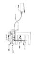
図1は、本発明が適用される正立型の顕微鏡装置の概略構成を示している。
【0021】
図において、31はレーザ光源で、このレーザ光源1から発せられるレーザ光の光路上には、集光レンズ32を介して光ファイバ33の入射端が配置され、集光レンズ32により集光されたレーザ光が入射される。
【0022】
光ファイバ33の出射端には、スキャンユニット34が配置されている。スキャンユニット34は、光ファイバ33内に導出され出射端から出射される光束の光路上に沿ってコリメートレンズ35、ダイクロイックミラー36およびスキャナ37が配置され、光ファイバ33から入射されるレーザ光をコリメートレンズ35で平行光に変換し、ダイクロイックミラー36を透過してスキャナ37に入射するようにしている。スキャナ37は、レーザ光源1からのレーザ光を偏向するとともに、この偏向角度を変更可能にしている。この場合、スキャナ37は、ミラーを回転させるようなタイプのものが用いられ、軸37aを中心に回転可能に支持され、レーザ光を直線方向(例えばX方向)にのみ偏向(スキャン)するようになっている。
【0023】
スキャンユニット34のダイクロイックミラー36は、標本47側からの蛍光を反射するもので、反射光路上には、吸収フィルタ38、ピンホール結像レンズ39、ピンホール40、集光レンズ41および受光素子としてのフォトマル42が配置されている。
【0024】
スキャナ37で偏向されるレーザ光の光路上には、結像レンズ43、対物レンズ44および顕微鏡本体45のステージ46上の標本47が配置されている。
【0025】
顕微鏡本体45には、対物像を偏向させる鏡筒49と、鏡筒49で偏向された対物像を目視で観察する接眼レンズ48が設けられている。
【0026】
スキャナ37と対物レンズ44との間の光路には、レンズ収納手段としてレンズ収納ユニット51が配置されている。このレンズ収納ユニット51は、第1の投影レンズとしての瞳投影レンズ52、第2の投影レンズとしての対物像投影レンズ53a、53bおよびダイクロイックミラー54を収納したユニット構成をなすもので、これら瞳投影レンズ52、対物像投影レンズ53a、53bおよびダイクロイックミラー54を図示しないレンズ切換え手段により選択的に光路上に切換え可能にしている。
【0027】
この場合、瞳投影レンズ52は、LSM画像を取得する際に光路上に挿入されるもので、スキャナ37で偏向されたレーザ光を結像レンズ43、対物レンズ44を介して標本47上に集光させるとともに、スキャナ37を対物レンズ44の射出瞳面44aに投影させるようにしている。ここで、スキャナ37を対物レンズ44の射出瞳面44aと共役の位置に設定しているのは、レーザ光をスキャンした場合に視野の周辺で、いわゆるケラレが発生するのを防止するためである。
【0028】
対物像投影レンズ53a、53bは、エバネッセント蛍光画像を取得する際に光路上に挿入されるもので、スキャナ37で偏向されて平行に出射されたレーザ光を結像レンズ43を介して対物レンズ44の射出瞳面44a上に集光させるとともに、スキャナ37を対物像面50へ投影させるようにしている。ここで、スキャナ37を対物像面50と共役の位置に設定しているのは、LSM画像を観察する場合に瞳投影レンズ52によりスキャナ37を対物レンズ44の射出瞳面44aに投影しているのと同じで、こうすることで、レーザ光を偏向した場合の視野の周辺での、いわゆるケラレの発生を防止している。また、対物像投影レンズ53a、53bは、ケプラータイプのアフォーカルコンバータに近いもので、これら対物像投影レンズ53a、53bの間に対物レンズ44の瞳の中間像44bを結像する内焦点式のものが用いられ、対物レンズ44の射出瞳面44aを無限遠に投影するとともに、スキャナ37を対物像面50へ投影するなどの働きを小さなスペースで可能にしている。
【0029】
ダイクロイックミラー54は、波長選択的に励起光となるレーザ光を透過するとともに、標本47から発せられる蛍光のみを反射するような特性を有するもので、この反射した蛍光を吸収フィルタ56を通してCCD55に入射させるようにしている。また、ダイクロイックミラー54は、対物像投影レンズ53a、53bと一体に構成され、対物像投影レンズ53a、53bとともに光路に挿脱されるようにしている。
【0030】
なお、これら瞳投影レンズ52と、対物像投影レンズ53a、53bおよびダイクロイックミラー54の光路に対する具体的な切換え手段は図示していないが、例えば、スライダーによるスライド切換え機構やターレットによる回転切換え手段など公知のレンズ切換え手段を用いることができる。
【0031】
また、このように構成されたレンズ収納ユニット51は、スキャナ37と対物レンズ44との間の光路に対して挿脱可能な構成になっている。
【0032】
このような構成において、まず、LSM画像の観察を行う場合を説明する。
【0033】
この場合、スキャナ37と対物レンズ44との間の光路に、レンズ収納ユニット51を挿入するとともに、図示しない切換え手段により瞳投影レンズ52を光路上に挿入する。図面では、光路上に挿入された瞳投影レンズ52と光路から外された対物像投影レンズ53a、53bおよびダイクロイックミラー54をそれぞれ破線で表わしている。
【0034】
レーザ光源31より発せられる平行のレーザ光は、集光レンズ32により光ファイバ33の入射端面に集光され、この光ファイバ33内を導光され出射端に達する。そして、光ファイバ33の出射端から出射されたレーザ光は、コリメートレンズ35により平行光にもどされ、ダイクロイックミラー36を透過してスキャナ37に導かれる。
【0035】
この状態で、スキャナ37は、光軸が折り返される点である軸37aを中心に回転され、コリメートレンズ35からのレーザ光は、標本47に向けて偏向される。ここで、スキャナ37により偏向されるレーザ光は、図示実線が光軸に平行に偏向された時の光線の状態、図示破線が光軸に対してある角度を持って偏向された時の光線の状態を表している。
【0036】
スキャナ37で偏向されたレーザ光は、瞳投影レンズ52、結像レンズ43、対物レンズ44を介して標本47上に集光される。
【0037】
この場合、スキャナ37は、瞳投影レンズ52により結像レンズ43を介して対物レンズ44の射出瞳面44aに投影され、対物レンズ44の射出瞳面44aと共役な位置に設定されている。
【0038】
このようにして、スキャナ37で偏向されたレーザ光は、標本47上に集光されるとともに、スキャナ37での偏向角度に応じたスキャンがなされる。
【0039】
一方、標本47上に集光されたレーザ光により励起され、標本47から発せられた蛍光は、対物レンズ44、結像レンズ43、瞳投影レンズ52、スキャナ37と上述したのと逆の光路をたどり、ダイクロイックミラー36に入射する。そして、このダイクロイックミラー36により反射されて、吸収フィルタ38を透過し、ピンホール結像レンズ39により標本47の像がピンホール40上に結像される。
【0040】
この場合、吸収フィルタ38は、励起光となるレーザ光をカットし標本47から発せられる観察に必要な蛍光の波長のみを透過するものが用いられている。また、ピンホール40は、標本47へのフォーカス面以外の画像成分をカットするようにしている。
【0041】
これにより、ピンホール40を通過した蛍光は、集光レンズ41を介してフォトマル42により受光され電気信号に変換される。そして、図示していないが、フォトマルの電気信号から画像を構成するための電気回路やソフトウェアなどの処理により画像として生成されてモニタ上に映し出され、LSM画像として観察可能となる。
【0042】
次に、エバネッセント蛍光観察を行う場合を説明する。
【0043】
この場合、図示しない切換え手段を用いて、瞳投影レンズ52を光路から外し、対物像投影レンズ53a、53bおよびダイクロイックミラー54を光路に挿入する。図面では、光路に挿入された対物像投影レンズ53a、53b、ダイクロイックミラー54と、光路から外された瞳投影レンズ52をそれぞれ実線で表わしている。
【0044】
この場合も、レーザ光源31から出射されたレーザ光は、光ファイバ33を介してコリメートレンズ35に入射される。次に、コリメートレンズ35で平行光束にされたレーザ光は、ダイクロイックミラー36を透過する。
【0045】
なお、エバネッセント蛍光観察の場合、ダイクロイックミラー36は、不要なので、明るさのロスを減らしたければ、光路から外すようにしてもよい。
【0046】
ダイクロイックミラー36を透過したレーザ光は、スキャナ37に導かれ、このスキャナ37で標本47側へ向けて偏向される。
【0047】
スキャナ37は、LSM画像の観察の場合と同様に偏向角度が可変となっており、ここでも図示実線が光軸に平行に偏向された時の光線の状態、図示破線が光軸に対してある角度を持って偏向された時の光線の状態を表している。
【0048】
ただし、エバネッセント蛍光観察の場合は、LSM画像の観察の場合と異なり像面をスキャンして画像構築を行う必要がないので、スキャナ37は、レーザ光の偏向角度の可変を所定角度の状態で停止される。
【0049】
スキャナ37で偏向されたレーザ光は、対物像投影レンズ53a、53b、ダイクロイックミラー54、結像レンズ43を介して対物レンズ44の射出瞳面44a上に集光される。
【0050】
この場合、スキャナ37は、対物像投影レンズ53a、53bにより対物像面50へ投影され、対物像面50と共役な位置に設定されている。
【0051】
これにより、対物レンズ44の射出瞳面44a上に集光されるレーザ光は、スキャナ37を回転させて偏向角度を変えるのみで、対物レンズ44の瞳中心から周辺までの範囲で移動することができる。
【0052】
この場合、図2に示すように、対物レンズ44の射出瞳面44a上に集光されるレーザ光が対物レンズ44の瞳中心付近のa〜bの範囲にあるときは、レーザ光は、対物レンズ44を介して光軸に平行に標本47を照明して通常の蛍光観察が可能となる。また、レーザ光が対物レンズ44の瞳周辺のb〜cの範囲にあるときは、レーザ光は、対物レンズ44を介して標本47を光軸に対して斜めに照明し、その角度が上述したように臨界角を超えることで、エバネッセント照明となってエバネッセント蛍光観察が可能となる。
【0053】
この場合、標本47は、細胞などの上にカバーガラスが貼り付けられた状態になっており、このためカバーガラスの屈折率によってエバネッセント照明になる臨界角は異なり、また、臨界角以上の角度でも、その角度によって細胞とカバーガラスの境界面から細胞側へしみでるエバネッセント光のしみだし深さも異なってくる。このしみだし深さは、標本47の、どの程度の深さまで観察したいかということであり、検鏡者の目的によっても異なる。
【0054】
このようにして、標本47の条件や、観察したい深さによって、標本47に照射されるレーザ光の角度は異なってくる。この場合、対物レンズ44の射出瞳面44aに集光されるレーザ光は、瞳の周辺に移動するにしたがって光軸に対する標本47への照射角度が大きくなるので、標本47の観察したい深さによって対物レンズ44の射出瞳面44aでの集光位置が異なってくる。また、光軸に対する標本47への照射角度が同じであっても、対物レンズ44の種類によっても射出瞳面44aでのレーザ光の集光位置も異なる。そこで、検鏡者は、これらのことを加味しながら、用途に応じてスキャナ37の偏向角度を最適な角度に設定してエバネッセント蛍光観察を行うことになる。
【0055】
一方、エバネッセント照明により標本47から発光した蛍光は、対物レンズ44、結像レンズ43を介してダイクロイックミラー54に入射し、このダイクロイックミラー54よりCCD55へ向けて反射され、吸収フィルタ56を介してCCD55の受光面でもある対物像面50へ投影される。
【0056】
この場合、吸収フィルタ56は、励起光となるレーザ光をカットし標本47から発する観察に必要な蛍光の波長のみを透過するものが用いられている。
【0057】
これにより、CCD55で撮像された対物像は、図示しないモニタ上に映し出され、エバネッセント蛍光画像として観察可能となる。
【0058】
従って、このようにすれば、スキャナ37と対物レンズ44との間の光路に瞳投影レンズ52と対物像投影レンズ53a、53bを収容するレンズ収納ユニット51を配置し、LSM画像の観察の場合は、瞳投影レンズ52を光路上に切換え、スキャナ37で偏向されたレーザ光を標本47上に集光させるとともに、スキャナ37を対物レンズ44の射出瞳面44aに投影させ、一方、エバネッセント蛍光観察の場合は、対物像投影レンズ53a、53bを光路上に切換え、スキャナ37で偏向されたレーザ光を対物レンズ44の射出瞳面44a上に集光させるとともに、スキャナ37を対物像面50へ投影させるようにしたので、従来のスキャンユニット内部でLSM画像と蛍光顕微鏡によるエバネッセント蛍光画像を取得するため2つの光路を切換えるようにしたものと比べ、光路切換えのための光学素子が必要でなくなり、構成を簡単にできるとともに、無駄な内部スペースを排除でき、顕微鏡自身の小型化も実現できる。また、共通のスキャナ37によりLSM画像とエバネッセント蛍光画像を選択的に取得できるので、従来のエバネッセント蛍光観察を行うため専用の平行平面板と、この平行平面板を精度よく回転駆動するための駆動手段を用意する必要のあるものと比べ、構成が簡単で、価格的にも安価にできる。
【0059】
また、スキャナ37と対物レンズ44との間の光路に配置されるレンズ収納ユニット51は、光路に対して挿脱可能なユニット構成になっているので、従来用いられている走査型レーザ顕微鏡を僅かに改造してレンズ収納ユニット51を装着できる構成とするだけで、実現可能である。
【0060】
さらに、LSM画像の観察の場合は、瞳投影レンズ52によりスキャナ37を対物レンズ44の射出瞳面44aに投影させ、エバネッセント蛍光観察の場合は、対物像投影レンズ53a、53bによりスキャナ37を対物像面50へ投影できるので、レーザ光をスキャンした場合に視野周辺でのケラレの発生を防止でき、適切な照明を行うことができる。
【0061】
さらにまた、スキャナ37は、LSM画像の観察では、レーザ光を所定角度の範囲で繰り返して偏向させるように使用され、エバネッセント蛍光観察では、所定の偏向角度の状態で停止して使用されるようになっており、これら動作の切換えはスキャナ37の図示しない駆動手段を制御するだけで簡単に得られるので、LSM画像の観察とエバネッセント蛍光観察の切換えを簡単に行うことができ、また、エバネッセント蛍光観察の際のエバネッセント照明の調節も、スキャナ37の偏向角度の停止位置を調整するだけで簡単に行うことができる。
【0062】
さらにまた、対物像投影レンズ53a、53bとダイクロイックミラー54は、一体に構成され、瞳投影レンズ52と選択的に光路上に切換えられるようになっているので、LSM画像の観察とエバネッセント蛍光観察をワンタッチ操作で切換えることができる。
【0063】
さらにまた、対物像投影レンズ53a、53bは、ケプラータイプのアフォーカルコンバータに近いもので、これら対物像投影レンズ53a、53bの間に対物レンズ44の瞳の中間像44bを結像する内焦点式のものが用いられるので、対物レンズ44の射出瞳面44aを無限遠に投影するとともに、スキャナ37を対物像面50へ投影するなどの働きを小さなスペースで実現できる。
【0064】
さらにまた、スキャナ37としてミラーを回転させるタイプのものを用いることで、対物レンズ44の射出瞳面44aでのレーザ光の集光位置を大きく移動させることができるので、通常の蛍光観察からエバネッセント観察までを簡単に調整することができる。
【0065】
なお、上述した実施の形態では、スキャナ37は、1個のみ設け、直線方向へ偏向(スキャン)する場合を示したが、2個設けて2次元的(XY方向)なスキャンを行うようにしてもよい。また、上述した実施の形態では、瞳投影レンズ52と対物像投影レンズ53a、53bを光路に対して交互に挿脱することで切換えを行うようにしたが、レンズ間隔を変更したり、どちらかのレンズの一部だけを挿脱するなどの他の手段を用いてレーザ光の集光位置を変更するようにしてもよい。さらに、上述した実施の形態では、対物像投影レンズ53a、53bとダイクロイックミラー54を一体構成として同時に光路から挿脱するようにしているが、必ずしも同時に挿脱する必要はなく、また、ダイクロイックミラー54は、結像レンズ43と対物レンズ44の間に配置してもよい。この場合は、エバネッセント蛍光像を結像させるために、ダイクロイックミラー54で反射させた後に別途結像レンズを設けるようにすればよい。さらに、ダイクロイックミラー36、54は、観察光路側を反射面にして配置されているが、これらダイクロイックミラー36、54の反射面の面精度の影響による像の劣化を少なくするためには、それぞれフォトマル42側とレーザ光源31側およびCCD55側とレーザ光源31側を逆の配置にしてもよい。さらに、対物レンズ44として結像レンズ43を用いない有限対物レンズとしてもよい。さらに、上述した実施の形態は、例えば、caged試薬解除装置や、ある1点の蛍光を強制的に退色させるFRAPなどに応用することもできる。さらに、上述した実施の形態では、一貫して正立型顕微鏡を例に説明したが、同様の構成で倒立型顕微鏡に適用することもできる。
【0066】
その他、本発明は、上記実施の形態に限定されるものでなく、実施段階では、その要旨を変更しない範囲で種々変形することが可能である。
【0067】
さらに、上記実施の形態には、種々の段階の発明が含まれており、開示されている複数の構成要件における適宜な組み合わせにより種々の発明が抽出できる。例えば、実施の形態に示されている全構成要件から幾つかの構成要件が削除されても、発明が解決しようとする課題の欄で述べた課題を解決でき、発明の効果の欄で述べられている効果が得られる場合には、この構成要件が削除された構成が発明として抽出できる。
【0068】
【発明の効果】
以上述べたように本発明によれば、簡単な構成で、しかも確実にLSM画像とエバネッセント蛍光画像を選択的に取得可能にした顕微鏡装置を提供できる。
【図面の簡単な説明】
【図1】本発明の一実施の形態の概略構成を示す図。
【図2】一実施の形態のエバネッセント蛍光観察を説明するための図。
【図3】従来の走査型レーザ顕微鏡の概略構成を示す図。
【図4】従来の蛍光顕微鏡の概略構成を示す図
【符号の説明】
31…レーザ光源
32…集光レンズ
33…光ファイバ
34…スキャンユニット
35…コリメートレンズ
36…ダイクロイックミラー
37…スキャナ
37a…軸
38…吸収フィルタ
39…ピンホール結像レンズ
40…ピンホール
41…集光レンズ
42…フォトマル
43…結像レンズ
44…対物レンズ
44a…射出瞳面
44b…中間像
45…顕微鏡本体
46…ステージ
47…標本
48…接眼レンズ
49…鏡筒
50…対物像面
51…レンズ収納ユニット
52…瞳投影レンズ
53a.53b…対物像投影レンズ
54…ダイクロイックミラー
55…CCD
56…吸収フィルタ[0001]
BACKGROUND OF THE INVENTION
The present invention relates to a microscope apparatus capable of selectively acquiring a confocal image (LSM image) by a laser microscope and an evanescent fluorescence image by a fluorescence microscope.
[0002]
[Prior art]
Recently, functional analysis of living cells has been actively performed. Among these functional analyzes of cells, in order to observe the function of the cell membrane, in particular, a fluorescence microscope that acquires an evanescent fluorescence image from the cell membrane and the vicinity thereof has attracted attention.
[0003]
This type of fluorescence microscope often uses laser light as a light source, and recently, a microscope capable of selectively acquiring a confocal image (LSM image) by a laser microscope and an evanescent fluorescence image by a fluorescence microscope. A device is considered.
[0004]
FIG. 3 shows a schematic configuration of a scanning laser microscope. Laser light emitted from a laser light source 1 is condensed on an incident end of an optical fiber 3 by a condensing lens 2 and passes through the optical fiber 3 from an emission end. The emitted light is converted into parallel light by the collimator lens 4, passes through the dichroic mirror 5, and enters the scanner 6. The scanner 6 is projected onto the exit pupil plane 9 a of the objective lens 9 by the pupil projection lens 7, and the laser beam deflected by the scanner 6 is placed on the stage 10 through the imaging lens 8 and the objective lens 9. The light is condensed and scanned in the X and Y directions, and the light from the specimen 11 is incident on the dichroic mirror 5 through the optical path opposite to that described above, and is reflected and reflected by the absorption filter 12, the pinhole imaging lens 13, and the pinhole 14. The LSM image is acquired by receiving light with the photomultiplier 16 via the
[0005]
On the other hand, FIG. 4 shows a schematic configuration of the fluorescence microscope, in which the laser light emitted from the laser light source 1 is condensed on the incident end of the optical fiber 3 by the condenser lens 2 and passes through the optical fiber 3 from the emission end. The emitted light beam is guided to the evanescent light projecting tube 17, converted into parallel light by the
[0006]
[Problems to be solved by the invention]
However, in order to selectively acquire the LSM image and the evanescent fluorescence image, if the respective configurations of the scanning laser microscope and the fluorescence microscope are prepared separately, the configuration becomes complicated and the operation becomes troublesome. In addition, there is a disadvantage that the whole apparatus becomes large and requires a large installation space, which is economically disadvantageous.
[0007]
On the other hand, Japanese Patent Application Laid-Open No. 6-27385 discloses a first optical path for condensing light from a light source through an objective lens on the specimen and spot illuminating the specimen, and light from the light source on the pupil plane of the objective lens. There has been disclosed a microscope in which the second optical path for condensing near and illuminating the field of view of the sample with a large beam diameter can be selectively switched.
[0008]
However, when the operation for acquiring the LSM image by the laser microscope and the evanescent fluorescence image by the fluorescence microscope is performed, the first and second optical paths are switched inside the scan unit. As a result, a large number of optical elements are required, and the configuration becomes complicated accordingly. Also, it is necessary to secure an internal space for this purpose, which causes problems such as an increase in size of the microscope itself.
[0009]
Therefore, as disclosed in the specification of Japanese Patent Application No. 2001-214373, a condensing lens that condenses the laser light at the pupil position of the objective lens and a predetermined distance offset in parallel to the laser light, the center of the objective lens A transparent parallel plane plate for allowing the laser beam to enter the position offset from the optical path of the laser beam is provided so as to be insertable / removable. LSM images can be acquired as described above. On the other hand, in the state where the condenser lens and the plane parallel plate are inserted in the optical path, the plane parallel plate is rotated to change the laser beam condensing position on the pupil plane of the objective lens. Therefore, it is possible to acquire an evanescent fluorescent image by evanescent illumination and to selectively acquire an LSM image and an evanescent fluorescent image. There.
[0010]
However, in this configuration, in order to perform evanescent fluorescence observation, a dedicated parallel plane plate must be prepared as a scanner that scans the laser beam on the pupil plane of the objective lens. Since driving means for rotationally driving with high precision is also required, there is a problem that the configuration becomes complicated and the cost becomes expensive.
[0011]
Therefore, it is conceivable that a scanner used for acquiring an LSM image cannot be used. However, in Japanese Patent Application No. 2001-214373, the evanescent fluorescence is observed in the optical path on the laser light source side from the scanner. Only the condensing lens for fluorescence observation is inserted, and the scanner cannot be projected onto the object image plane, so the laser light is moved slightly to scan the laser light to shift the condensing point of the laser light. Then, so-called vignetting occurs around the field of view, and appropriate evanescent illumination cannot be performed.
[0012]
The present invention has been made in view of the above circumstances, and an object of the present invention is to provide a microscope apparatus that can selectively acquire an LSM image and an evanescent fluorescence image with a simple configuration.
[0013]
[Means for Solving the Problems]
According to a first aspect of the present invention, the light source for illuminating the specimen, the scanner for deflecting the illumination light from the light source and the deflection angle of which can be changed, and the optical path of the illumination light deflected by the scanner are arranged. , An objective lens that projects the image of the specimen, and a first lens that is disposed between the scanner and the objective lens, and that condenses the illumination light deflected by the scanner onto the specimen via the objective lens. A projection lens; and a second projection lens that is disposed between the scanner and the objective lens and collects illumination light deflected by the scanner on a pupil plane of the objective lens, The first and second projection lenses can be selectively inserted into the optical path.
[0014]
According to a second aspect of the present invention, in the first aspect of the present invention, the first and second projection lenses are stored in a unit containing lens storage means, and the lens storage means includes the scanner and the objective lens. It is characterized in that it can be inserted into and removed from the optical path between.
[0015]
According to a third aspect of the present invention, in the first or second aspect of the invention, the scanner may change the deflection angle of the illumination light at a predetermined angle in a state where the second projection lens is inserted in the optical path. The feature is that it can be stopped.
[0016]
As a result, according to the present invention, when the LSM image is observed by the lens switching unit, the illumination light deflected by the scanner is condensed on the specimen by switching the first projection lens on the optical path, and evanescent fluorescence is collected. In the case of observation, since the illumination light deflected by the scanner is condensed on the pupil plane of the objective lens by switching the second projection lens on the optical path, the LSM image can be surely obtained with a simple configuration. An evanescent fluorescence image can be selectively acquired.
[0017]
Further, according to the present invention, since the lens storage means has a unit configuration that can be inserted into and removed from the optical path, the lens switching means can be mounted by slightly modifying a conventionally used scanning laser microscope. It can be applied simply by configuring.
[0018]
Furthermore, according to the present invention, it is possible to adjust the evanescent illumination during the evanescent fluorescence observation only by determining the stop position of the deflection angle of the scanner.
According to a fourth aspect of the present invention, there is provided a light source for illuminating a specimen, a scanner for deflecting illumination light from the light source, the deflection angle being changeable, and an optical path of illumination light deflected by the scanner And an objective lens that projects an image of the specimen, and is arranged between the scanner and the objective lens, and the illumination light deflected by the scanner is condensed on the specimen via the objective lens. And a lens means capable of switching between a second state for condensing the illumination light on the pupil plane of the objective lens, and the scanner is conjugate with the objective image plane in the second state. It is characterized by being.
According to a fifth aspect of the present invention, in the fourth aspect of the present invention, the first light receiving element that receives light from the sample when the lens means is in the first state, and the lens means is the second A first light receiving element that receives light from the specimen when in the state; and a dichroic mirror that guides light from the specimen to the second light receiving element when in the second state; In this state, light from the sample is received by the first light receiving element to acquire an LSM image, and in the second state, light from the sample is received by the second light receiving element. Thus, an evanescent fluorescence image is acquired.
The invention of claim 6 is characterized in that, in the invention of claim 5, the depth of evanescent light oozing is varied by changing the stop position of the deflection angle of the scanner in the second state.
According to a seventh aspect of the present invention, in the fourth to sixth aspects of the invention, the condensing position on the pupil plane of the objective lens is varied by changing a deflection angle of the scanner in the second state. It is said.
The invention of claim 8 is characterized in that, in the invention of claim 5, the stop position of the deflection angle of the scanner is varied according to the type of the objective lens in the second state.
A ninth aspect of the invention is characterized in that, in the first to third aspects of the invention, when the second projection lens is inserted, the scanner is conjugate with the object image plane.
The invention of claim 10 is arranged in a light source for illuminating a specimen, a scanner for deflecting illumination light from the light source and changing the deflection angle, and an optical path of illumination light deflected by the scanner, An objective lens that projects an image of the specimen; and a microscope apparatus that forms a scanned image of the specimen by scanning the illumination light condensed by the objective lens with the scanner. The scanner and the objective lens And a projection lens that condenses the illumination light on the pupil plane of the objective lens and conjugates the scanner with the objective image plane, and the illumination light deflected by the scanner is Evanescent illumination of the specimen is made possible by focusing light on the periphery of the pupil plane of the objective lens through the projection lens. That.
[0019]
DETAILED DESCRIPTION OF THE INVENTION
Hereinafter, an embodiment of the present invention will be described with reference to the drawings.
[0020]
FIG. 1 shows a schematic configuration of an upright microscope apparatus to which the present invention is applied.
[0021]
In the figure, reference numeral 31 denotes a laser light source. On the optical path of the laser light emitted from the laser light source 1, an incident end of an optical fiber 33 is disposed via a condensing lens 32 and is condensed by the condensing lens 32. Laser light is incident.
[0022]
A scan unit 34 is disposed at the emission end of the optical fiber 33. The scan unit 34 includes a collimating lens 35, a dichroic mirror 36, and a scanner 37 disposed along the optical path of a light beam led out into the optical fiber 33 and emitted from the exit end, and collimates the laser light incident from the optical fiber 33. The lens 35 converts the light into parallel light, passes through the dichroic mirror 36, and enters the scanner 37. The scanner 37 deflects the laser light from the laser light source 1 and changes the deflection angle. In this case, the scanner 37 is of a type that rotates a mirror, is supported rotatably about an
[0023]
The dichroic mirror 36 of the scan unit 34 reflects fluorescence from the
[0024]
On the optical path of the laser light deflected by the scanner 37, an imaging lens 43, an
[0025]
The microscope main body 45 is provided with a lens barrel 49 for deflecting the objective image and an eyepiece lens 48 for visually observing the objective image deflected by the lens barrel 49.
[0026]
A lens storage unit 51 is disposed in the optical path between the scanner 37 and the
[0027]
In this case, the
[0028]
The objective
[0029]
The
[0030]
Although specific switching means for the optical paths of the
[0031]
Further, the lens storage unit 51 configured as described above is configured to be detachable with respect to the optical path between the scanner 37 and the
[0032]
In such a configuration, first, a case where an LSM image is observed will be described.
[0033]
In this case, the lens storage unit 51 is inserted into the optical path between the scanner 37 and the
[0034]
Parallel laser light emitted from the laser light source 31 is condensed on the incident end face of the optical fiber 33 by the condenser lens 32, guided in the optical fiber 33, and reaches the emission end. The laser light emitted from the emission end of the optical fiber 33 is returned to parallel light by the collimating lens 35, passes through the dichroic mirror 36, and is guided to the scanner 37.
[0035]
In this state, the scanner 37 is rotated around an
[0036]
The laser light deflected by the scanner 37 is condensed on the
[0037]
In this case, the scanner 37 is projected onto the exit pupil plane 44a of the
[0038]
In this way, the laser light deflected by the scanner 37 is condensed on the
[0039]
On the other hand, the fluorescence emitted from the
[0040]
In this case, as the absorption filter 38, a filter that cuts off the laser light serving as excitation light and transmits only the fluorescence wavelength necessary for observation emitted from the
[0041]
As a result, the fluorescence that has passed through the pinhole 40 is received by the photomultiplier 42 via the
[0042]
Next, a case where evanescent fluorescence observation is performed will be described.
[0043]
In this case, the
[0044]
Also in this case, the laser light emitted from the laser light source 31 enters the collimating lens 35 via the optical fiber 33. Next, the laser light converted into a parallel light beam by the collimating lens 35 passes through the dichroic mirror 36.
[0045]
In the case of evanescent fluorescence observation, the dichroic mirror 36 is unnecessary, and may be removed from the optical path to reduce the loss of brightness.
[0046]
The laser light transmitted through the dichroic mirror 36 is guided to the scanner 37 and deflected toward the
[0047]
In the scanner 37, the deflection angle is variable as in the case of observing the LSM image. Here, the state of the light beam when the illustrated solid line is deflected parallel to the optical axis, and the broken line illustrated in FIG. It represents the state of the light beam when deflected at an angle.
[0048]
However, in the case of the evanescent fluorescence observation, unlike the case of the observation of the LSM image, it is not necessary to perform image construction by scanning the image plane, so the scanner 37 stops changing the deflection angle of the laser light at a predetermined angle. Is done.
[0049]
The laser light deflected by the scanner 37 is condensed on the exit pupil plane 44 a of the
[0050]
In this case, the scanner 37 is projected onto the objective image plane 50 by the objective
[0051]
As a result, the laser light condensed on the exit pupil plane 44a of the
[0052]
In this case, as shown in FIG. 2, when the laser beam condensed on the exit pupil plane 44 a of the
[0053]
In this case, the
[0054]
In this way, the angle of the laser light applied to the
[0055]
On the other hand, the fluorescence emitted from the
[0056]
In this case, as the absorption filter 56, a filter that cuts off laser light serving as excitation light and transmits only the fluorescence wavelength necessary for observation emitted from the
[0057]
As a result, the objective image picked up by the CCD 55 is displayed on a monitor (not shown) and can be observed as an evanescent fluorescence image.
[0058]
Accordingly, in this case, the lens housing unit 51 that houses the
[0059]
Further, since the lens storage unit 51 arranged in the optical path between the scanner 37 and the
[0060]
Further, in the case of LSM image observation, the scanner 37 is projected onto the exit pupil plane 44a of the
[0061]
Furthermore, the scanner 37 is used to repeatedly deflect the laser beam within a predetermined angle range in the observation of the LSM image, and is stopped and used in the state of the predetermined deflection angle in the evanescent fluorescence observation. Since the switching of these operations can be easily obtained by simply controlling the driving means (not shown) of the scanner 37, the switching between the LSM image observation and the evanescent fluorescence observation can be easily performed, and the evanescent fluorescence observation is possible. The evanescent illumination can be easily adjusted by simply adjusting the stop position of the deflection angle of the scanner 37.
[0062]
Furthermore, since the objective
[0063]
Furthermore, the objective
[0064]
Furthermore, by using a scanner that rotates the mirror as the scanner 37, the condensing position of the laser light on the exit pupil plane 44a of the
[0065]
In the above-described embodiment, only one scanner 37 is provided and deflected (scanned) in the linear direction. However, two scanners 37 are provided to perform two-dimensional (XY direction) scanning. Also good. In the above-described embodiment, the switching is performed by alternately inserting and removing the
[0066]
In addition, this invention is not limited to the said embodiment, In the implementation stage, it can change variously in the range which does not change the summary.
[0067]
Furthermore, the above embodiments include inventions at various stages, and various inventions can be extracted by appropriately combining a plurality of disclosed constituent elements. For example, even if some constituent requirements are deleted from all the constituent requirements shown in the embodiment, the problem described in the column of the problem to be solved by the invention can be solved, and is described in the column of the effect of the invention. If the above effect is obtained, a configuration from which this configuration requirement is deleted can be extracted as an invention.
[0068]
【The invention's effect】
As described above, according to the present invention, it is possible to provide a microscope apparatus capable of selectively acquiring an LSM image and an evanescent fluorescence image with a simple configuration.
[Brief description of the drawings]
FIG. 1 is a diagram showing a schematic configuration of an embodiment of the present invention.
FIG. 2 is a diagram for explaining evanescent fluorescence observation according to one embodiment.
FIG. 3 is a diagram showing a schematic configuration of a conventional scanning laser microscope.
FIG. 4 is a diagram showing a schematic configuration of a conventional fluorescence microscope
[Explanation of symbols]
31 ... Laser light source
32 ... Condensing lens
33 ... Optical fiber
34 ... Scanning unit
35 ... Collimating lens
36 ... Dichroic mirror
37 ... Scanner
37a ... axis
38 ... Absorption filter
39 ... Pinhole imaging lens
40 ... pinhole
41 ... Condensing lens
42 ... Photomaru
43 ... Imaging lens
44 ... Objective lens
44a ... exit pupil plane
44b ... Intermediate image
45 ... Microscope body
46 ... Stage
47 ... Sample
48 ... Eyepiece
49 ... Tube
50: Objective image plane
51 ... Lens storage unit
52 ... Pupil projection lens
53a. 53b ... Objective image projection lens
54 ... Dichroic mirror
55 ... CCD
56 ... Absorption filter
Claims (10)
前記光源からの照明光を偏向するとともに、この偏向角度を変更可能にしたスキャナと、
前記スキャナで偏向される照明光の光路に配置され、前記標本の像を投影する対物レンズと、
前記スキャナと前記対物レンズとの間に配置され、前記スキャナで偏向された照明光を前記対物レンズを介して前記標本上に集光させる第1の投影レンズと、
前記スキャナと前記対物レンズとの間に配置され、前記スキャナで偏向された照明光を前記対物レンズの瞳面上に集光させる第2の投影レンズと、
を具備し、前記第1および第2の投影レンズを選択的に前記光路に挿入可能にしたことを特徴とする顕微鏡装置。A light source for illuminating the specimen;
A scanner that deflects illumination light from the light source and that can change the deflection angle;
An objective lens that is disposed in an optical path of illumination light deflected by the scanner and projects an image of the specimen;
A first projection lens disposed between the scanner and the objective lens, and condensing the illumination light deflected by the scanner onto the specimen via the objective lens;
A second projection lens disposed between the scanner and the objective lens and condensing the illumination light deflected by the scanner on the pupil plane of the objective lens;
And a microscope apparatus characterized in that the first and second projection lenses can be selectively inserted into the optical path.
該レンズ収納手段を前記スキャナと前記対物レンズとの間の光路に挿脱可能にしたことを特徴とする請求項1記載の顕微鏡装置。A lens housing means having a unit configuration housing the first and second projection lenses
2. The microscope apparatus according to claim 1, wherein the lens storage means can be inserted into and removed from an optical path between the scanner and the objective lens.
前記光源からの照明光を偏向するとともに、この偏向角度を変更可能にしたスキャナと、A scanner that deflects illumination light from the light source and that can change the deflection angle;
前記スキャナで偏向される照明光の光路に配置され、前記標本の像を投影する対物レンズと、An objective lens that is arranged in an optical path of illumination light deflected by the scanner and projects an image of the specimen;
前記スキャナと前記対物レンズとの間に配置され、前記スキャナで偏向された照明光を前記対物レンズを介して前記標本上に集光させる第1の状態と前記照明光を前記対物レンズの瞳面上に集光させる第2の状態を切換可能なレンズ手段とを具備し、A first state in which illumination light, which is disposed between the scanner and the objective lens and is deflected by the scanner, is condensed on the sample via the objective lens, and the pupil plane of the objective lens Lens means capable of switching the second state of focusing on, and
前記スキャナは前記第2の状態のときに対物像面と共役であることを特徴とする顕微鏡装置。The microscope apparatus according to claim 1, wherein the scanner is conjugate with an object image plane in the second state.
前記レンズ手段が前記第2の状態のときに前記標本からの光を受光する第2の受光素子と、A second light receiving element for receiving light from the specimen when the lens means is in the second state;
前記第2の状態のときに前記標本からの光を前記第2の受光素子へ導くダイクロイックミラーとを備え、A dichroic mirror for guiding light from the specimen to the second light receiving element in the second state;
前記第1の状態のときに前記標本からの光を前記第1の受光素子で受光してLSM画像を取得し、前記第2の状態のときに前記標本からの光を前記第2の受光素子で受光してエバネッセント蛍光画像を取得するようにしたことを特徴とする請求項4に記載の顕微鏡装置。Light from the specimen is received by the first light receiving element in the first state to acquire an LSM image, and light from the specimen is received in the second light receiving element in the second state. 5. The microscope apparatus according to claim 4, wherein an evanescent fluorescence image is acquired by receiving the light.
前記光源からの照明光を偏向するとともに、この偏向角度を変更可能にしたスキャナと、A scanner that deflects illumination light from the light source and that can change the deflection angle;
前記スキャナで偏向される照明光の光路に配置され、前記標本の像を投影する対物レンズとを備え、前記対物レンズによって集光される前記照明光を前記スキャナによって走査することにより前記標本の走査画像を形成する顕微鏡装置において、An objective lens that is disposed in an optical path of illumination light deflected by the scanner and projects an image of the specimen, and scans the specimen by scanning the illumination light condensed by the objective lens with the scanner. In a microscope apparatus for forming an image,
前記スキャナと前記対物レンズとの間に配置され、前記照明光を前記対物レンズの瞳面上に集光させるとともに前記スキャナと対物像面を共役関係にする投影レンズを具備し、A projection lens that is disposed between the scanner and the objective lens, condenses the illumination light on the pupil plane of the objective lens and conjugates the scanner and the objective image plane;
前記スキャナで偏向された前記照明光を前記投影レンズを介して前記対物レンズの瞳面の周辺に集光させることによって、前記標本のエバネッセント照明を可能にしたことを特徴とする顕微鏡装置。The microscope apparatus, wherein the illumination light deflected by the scanner is condensed on the periphery of the pupil plane of the objective lens through the projection lens, thereby enabling evanescent illumination of the specimen.
Priority Applications (1)
| Application Number | Priority Date | Filing Date | Title |
|---|---|---|---|
| JP2002112303A JP4128387B2 (en) | 2002-04-15 | 2002-04-15 | Microscope equipment |
Applications Claiming Priority (1)
| Application Number | Priority Date | Filing Date | Title |
|---|---|---|---|
| JP2002112303A JP4128387B2 (en) | 2002-04-15 | 2002-04-15 | Microscope equipment |
Publications (3)
| Publication Number | Publication Date |
|---|---|
| JP2003307682A JP2003307682A (en) | 2003-10-31 |
| JP2003307682A5 JP2003307682A5 (en) | 2005-09-22 |
| JP4128387B2 true JP4128387B2 (en) | 2008-07-30 |
Family
ID=29394848
Family Applications (1)
| Application Number | Title | Priority Date | Filing Date |
|---|---|---|---|
| JP2002112303A Expired - Fee Related JP4128387B2 (en) | 2002-04-15 | 2002-04-15 | Microscope equipment |
Country Status (1)
| Country | Link |
|---|---|
| JP (1) | JP4128387B2 (en) |
Families Citing this family (11)
| Publication number | Priority date | Publication date | Assignee | Title |
|---|---|---|---|---|
| WO2005029149A1 (en) * | 2003-09-25 | 2005-03-31 | Leica Microsystems Cms Gmbh | Microscope with evanescent wave illumination |
| JP2005300655A (en) * | 2004-04-07 | 2005-10-27 | Olympus Corp | Laser-scanning observation apparatus |
| WO2005121862A1 (en) * | 2004-06-14 | 2005-12-22 | Olympus Corporation | Optical scanning microscope observing device |
| JP4545492B2 (en) * | 2004-06-14 | 2010-09-15 | オリンパス株式会社 | Optical scanning microscope |
| JP4602731B2 (en) * | 2004-10-05 | 2010-12-22 | オリンパス株式会社 | Microscope system |
| JP4652775B2 (en) * | 2004-11-10 | 2011-03-16 | オリンパス株式会社 | Living body observation device |
| US7609440B2 (en) | 2004-11-10 | 2009-10-27 | Olympus Corporation | In-vivo examination apparatus |
| JP4700334B2 (en) * | 2004-12-07 | 2011-06-15 | オリンパス株式会社 | Total reflection fluorescence microscope |
| JP2006208681A (en) * | 2005-01-27 | 2006-08-10 | Olympus Corp | Connection unit and optical scanning type fluorescent observation device |
| JP4924146B2 (en) * | 2007-03-30 | 2012-04-25 | 横河電機株式会社 | Confocal microscope system |
| JP5537255B2 (en) * | 2010-05-17 | 2014-07-02 | オリンパス株式会社 | Non-confocal detection optical system and multiphoton excitation microscope equipped with the same |
-
2002
- 2002-04-15 JP JP2002112303A patent/JP4128387B2/en not_active Expired - Fee Related
Also Published As
| Publication number | Publication date |
|---|---|
| JP2003307682A (en) | 2003-10-31 |
Similar Documents
| Publication | Publication Date | Title |
|---|---|---|
| JP5006694B2 (en) | Lighting device | |
| US7589839B2 (en) | Examination apparatus, fluoroscopy apparatus, examination method, and experimental method | |
| JP4812179B2 (en) | Laser microscope | |
| EP1857853B1 (en) | Illuminating device | |
| US7573635B2 (en) | Microscope device | |
| JP4242617B2 (en) | Scanning laser microscope system | |
| US7480046B2 (en) | Scanning microscope with evanescent wave illumination | |
| JP2004070276A (en) | Automatic focusing device | |
| JP5286774B2 (en) | Microscope device and fluorescent cube used therefor | |
| US20100172021A1 (en) | Laser microscope | |
| US6924490B2 (en) | Microscope system | |
| JP4128387B2 (en) | Microscope equipment | |
| JP2011118264A (en) | Microscope device | |
| JP4854880B2 (en) | Laser microscope | |
| JP2006171024A (en) | Multi-point fluorescence spectrophotometry microscope and multi-point fluorescence spectrophotometry method | |
| US6917468B2 (en) | Confocal microscope | |
| JP3861357B2 (en) | Microscope revolver and microscope integrated with optical device | |
| JP2005274591A (en) | Confocal microscope | |
| JP2011118265A (en) | Microscope device | |
| JP4593141B2 (en) | Optical scanning observation device | |
| JP4792230B2 (en) | Fluorescence microscope device | |
| JP3995458B2 (en) | Total reflection fluorescence microscope | |
| JP4700334B2 (en) | Total reflection fluorescence microscope | |
| JP2002517003A (en) | Near-field optical microscope | |
| JP2005010516A (en) | Microscope |
Legal Events
| Date | Code | Title | Description |
|---|---|---|---|
| A521 | Written amendment |
Free format text: JAPANESE INTERMEDIATE CODE: A523 Effective date: 20050414 |
|
| A621 | Written request for application examination |
Free format text: JAPANESE INTERMEDIATE CODE: A621 Effective date: 20050414 |
|
| A977 | Report on retrieval |
Free format text: JAPANESE INTERMEDIATE CODE: A971007 Effective date: 20070920 |
|
| TRDD | Decision of grant or rejection written | ||
| A01 | Written decision to grant a patent or to grant a registration (utility model) |
Free format text: JAPANESE INTERMEDIATE CODE: A01 Effective date: 20080507 |
|
| A01 | Written decision to grant a patent or to grant a registration (utility model) |
Free format text: JAPANESE INTERMEDIATE CODE: A01 |
|
| A61 | First payment of annual fees (during grant procedure) |
Free format text: JAPANESE INTERMEDIATE CODE: A61 Effective date: 20080514 |
|
| FPAY | Renewal fee payment (event date is renewal date of database) |
Free format text: PAYMENT UNTIL: 20110523 Year of fee payment: 3 |
|
| R151 | Written notification of patent or utility model registration |
Ref document number: 4128387 Country of ref document: JP Free format text: JAPANESE INTERMEDIATE CODE: R151 |
|
| FPAY | Renewal fee payment (event date is renewal date of database) |
Free format text: PAYMENT UNTIL: 20110523 Year of fee payment: 3 |
|
| FPAY | Renewal fee payment (event date is renewal date of database) |
Free format text: PAYMENT UNTIL: 20120523 Year of fee payment: 4 |
|
| FPAY | Renewal fee payment (event date is renewal date of database) |
Free format text: PAYMENT UNTIL: 20130523 Year of fee payment: 5 |
|
| FPAY | Renewal fee payment (event date is renewal date of database) |
Free format text: PAYMENT UNTIL: 20140523 Year of fee payment: 6 |
|
| S531 | Written request for registration of change of domicile |
Free format text: JAPANESE INTERMEDIATE CODE: R313531 |
|
| R350 | Written notification of registration of transfer |
Free format text: JAPANESE INTERMEDIATE CODE: R350 |
|
| LAPS | Cancellation because of no payment of annual fees |