JP4932162B2 - Focus detection device and fluorescence observation device using the same - Google Patents
Focus detection device and fluorescence observation device using the same Download PDFInfo
- Publication number
- JP4932162B2 JP4932162B2 JP2005012824A JP2005012824A JP4932162B2 JP 4932162 B2 JP4932162 B2 JP 4932162B2 JP 2005012824 A JP2005012824 A JP 2005012824A JP 2005012824 A JP2005012824 A JP 2005012824A JP 4932162 B2 JP4932162 B2 JP 4932162B2
- Authority
- JP
- Japan
- Prior art keywords
- light
- focus detection
- objective lens
- boundary surface
- specimen
- Prior art date
- Legal status (The legal status is an assumption and is not a legal conclusion. Google has not performed a legal analysis and makes no representation as to the accuracy of the status listed.)
- Expired - Fee Related
Links
- 238000001514 detection method Methods 0.000 title claims description 179
- 230000003287 optical effect Effects 0.000 claims description 72
- 238000005286 illumination Methods 0.000 claims description 66
- 238000003384 imaging method Methods 0.000 claims description 7
- 230000002093 peripheral effect Effects 0.000 claims description 6
- 238000002073 fluorescence micrograph Methods 0.000 claims description 3
- 230000005540 biological transmission Effects 0.000 claims description 2
- 230000004907 flux Effects 0.000 claims 2
- 239000006059 cover glass Substances 0.000 description 51
- 239000000523 sample Substances 0.000 description 19
- 230000000694 effects Effects 0.000 description 8
- 230000005284 excitation Effects 0.000 description 7
- 238000010586 diagram Methods 0.000 description 5
- 239000011521 glass Substances 0.000 description 5
- 230000035515 penetration Effects 0.000 description 5
- 238000000034 method Methods 0.000 description 4
- 238000002474 experimental method Methods 0.000 description 3
- 239000002184 metal Substances 0.000 description 3
- 210000001747 pupil Anatomy 0.000 description 3
- 239000007864 aqueous solution Substances 0.000 description 2
- 230000004071 biological effect Effects 0.000 description 2
- 238000007654 immersion Methods 0.000 description 2
- 238000012986 modification Methods 0.000 description 2
- 230000004048 modification Effects 0.000 description 2
- 230000009286 beneficial effect Effects 0.000 description 1
- 230000000903 blocking effect Effects 0.000 description 1
- 239000000470 constituent Substances 0.000 description 1
- 238000005516 engineering process Methods 0.000 description 1
- 238000005562 fading Methods 0.000 description 1
- 238000007689 inspection Methods 0.000 description 1
- 230000001902 propagating effect Effects 0.000 description 1
- 239000012488 sample solution Substances 0.000 description 1
- 230000000007 visual effect Effects 0.000 description 1
Images


Classifications
-
- G—PHYSICS
- G02—OPTICS
- G02B—OPTICAL ELEMENTS, SYSTEMS OR APPARATUS
- G02B21/00—Microscopes
- G02B21/0004—Microscopes specially adapted for specific applications
- G02B21/0088—Inverse microscopes
-
- G—PHYSICS
- G02—OPTICS
- G02B—OPTICAL ELEMENTS, SYSTEMS OR APPARATUS
- G02B21/00—Microscopes
- G02B21/16—Microscopes adapted for ultraviolet illumination ; Fluorescence microscopes
-
- G—PHYSICS
- G02—OPTICS
- G02B—OPTICAL ELEMENTS, SYSTEMS OR APPARATUS
- G02B21/00—Microscopes
- G02B21/24—Base structure
- G02B21/241—Devices for focusing
- G02B21/244—Devices for focusing using image analysis techniques
-
- G—PHYSICS
- G02—OPTICS
- G02B—OPTICAL ELEMENTS, SYSTEMS OR APPARATUS
- G02B21/00—Microscopes
- G02B21/24—Base structure
- G02B21/241—Devices for focusing
- G02B21/245—Devices for focusing using auxiliary sources, detectors
Description
本発明は、焦点検出装置とそれを用いた蛍光観察装置に関し、特に、生細胞を高コントラストで蛍光観察する顕微鏡や光学装置において、観察対象となる観察標本の搭載されたガラス面と観察標本の界面位置を高い精度で検出することができる装置に関する。 The present invention relates to a focus detection apparatus and a fluorescence observation apparatus using the focus detection apparatus, and in particular, in a microscope or an optical apparatus that performs fluorescence observation of living cells with high contrast, a glass surface on which an observation specimen to be observed and an observation specimen are mounted. The present invention relates to an apparatus capable of detecting an interface position with high accuracy.
生物研究分野では、蛍光観察法を利用して細胞内部の機能、構造解析が行われている。しかしながら、通常の蛍光観察では照明光が観察対象物全体に照射されるため、観察したい位置以外(ピントの合っていない位置)の蛍光情報も同時に取得される。そのため、コントラストが低下してしまい、例えば1分子といった微小単位の観察を行うことができなかった。 In the biological research field, functions and structures of cells are analyzed using fluorescence observation methods. However, in normal fluorescence observation, illumination light is irradiated to the entire observation object, and therefore fluorescence information other than the position where the observation is desired (the position where the focus is not in focus) is also acquired at the same time. For this reason, the contrast is lowered, and it is impossible to observe a minute unit such as one molecule.
近年、光の全反射時に発生するエバネッセント光を照明光として利用し、数十から数百nmといった微小領域のみを照明する技術が確立したことで、通常の蛍光観察の問題点である上記コントラストの低下を防止し、1分子レベルの微小単位の蛍光観察が可能となってきている。 In recent years, the evanescent light generated at the time of total reflection of light is used as illumination light, and a technology for illuminating only a small region of several tens to several hundreds of nanometers has been established. It is possible to observe the fluorescence of minute units at the level of one molecule while preventing the decrease.
エバネッセント光は、屈折率の異なる境界面に、ある一定値以下の角度で照明光を入射させたときに、その照明光を全反射させることによって発生する光である。また、エバネッセント光は、上記境界面に対して照明光とは反対側に、波長より小さい寸法の領域に局在する、自由空間を伝播しない特性をもつ。 The evanescent light is light generated by totally reflecting the illumination light when the illumination light is incident on the boundary surfaces having different refractive indexes at an angle of a certain value or less. In addition, evanescent light has the property of not propagating in free space, which is localized in a region having a size smaller than the wavelength, on the opposite side of the boundary surface from the illumination light.
生物研究では、生細胞内での経時変化を見るためにしばしばタイムラプスと言われる手法がとられている。この手法は、例えば1日、2日といった期間内で連続または一定間隔で観察像を取得することで細胞内部の機能を解析することを目的としている。 In biological research, a technique often referred to as time-lapse is used to observe changes over time in living cells. This method is intended to analyze the function inside the cell by acquiring observation images continuously or at regular intervals within a period of, for example, 1 day or 2 days.
この手法においては、長期間におよぶ観察が必要となるが、観察装置である顕微鏡は金属とガラスの集合体であり、例えば実験を行う部屋の内部温度が僅かに変化しただけでも顕微鏡が変形し、ピント位置がずれるという問題が発生する。特に、数十から数百nmといった微小領域を観察するエバネッセント光を利用した蛍光観察では、大きな問題となっている。 Although this method requires observation over a long period of time, the microscope, which is an observation device, is an aggregate of metal and glass. For example, even if the internal temperature of the room in which the experiment is performed changes slightly, the microscope deforms. The problem that the focus position shifts occurs. In particular, fluorescence observation using evanescent light for observing a minute region of several tens to several hundreds of nm is a big problem.
特許文献1では、焦点検出専用のエバネッセント光を利用することで、そのエバネッセント場に存在する細胞の一部を高精度で位置検出する手段が開示されている。
図11に示すように、焦点検出用のレーザ光90をカバーガラス91と試料溶液96中の観察試料92との界面91aで全反射するように入射し、カバーガラス表面にエバネッセント光を浸み出させる。このエバネッセント光の存在する領域つまりエバネッセント場に位置する観察標本92は前記エバネッセント光により散乱光93を生じる。その散乱光93を対物レンズ94で集光し、受光素子95で検出してその受光強度の最も大きな位置を合焦位置とする。この位置情報から対物レンズ94の焦点位置を制御している。試料を蛍光観察するための光源はさらに別にあり、焦点検出用のレーザ光90は赤外光を用いる事で細胞に与えるダメージを少なくする事ができる。
ところが特許文献1に記載の発明では、細胞による散乱光強度を検出しているため、合焦精度、位置が細胞の数や状態によって振られることや、フォーカス調整時の散乱光強度変化が微小であり検出精度が劣化することが予想される。
However, in the invention described in
また焦点を合わせるために用いている基準点が散乱光を発生する試料の一部であるため、生細胞などを観察標本としている場合、基準点とした散乱光を発生する観察標本の一部が動くことが予想され、焦点調整が定まらないことになる。例えば、焦点調整に用いていた細胞の一部が上方向に移動し、実際に観察していた部位が動かなかった時、観察している部位はピントボケになってしまう。 In addition, since the reference point used for focusing is a part of the sample that generates scattered light, when a living cell or the like is used as the observation sample, a part of the observation sample that generates the scattered light using the reference point is used. It is expected to move, and the focus adjustment will not be determined. For example, when a part of the cell used for focus adjustment moves upward and the actually observed part does not move, the observed part becomes out of focus.
本発明は、エバネッセント光を利用した高コントラストの蛍光観察において、試料である細胞の状態等に影響なく高合焦精度を実現することを目的とする。 An object of the present invention is to achieve high focusing accuracy without affecting the state of a cell as a sample in high contrast fluorescence observation using evanescent light.
本発明に係る発明は、標本を観察する対物レンズと、前記標本の屈折率とは異なる屈折率をもち、前記標本を載置する透明部材と、前記対物レンズの外周部分を通して、前記標本と前記透明部材との境界面で全反射するように照明光を照射する照明光源と、前記対物レンズと撮像素子との間に配置された焦点検出用のダイクロイックミラーと、前記ダイクロイックミラーのうち前記境界面からの反射光を反射させる反射面側に配置された半透過ミラーと、前記半透過ミラーのうち前記境界面からの反射光を反射させる反射面側に設けられ、焦点検出用の検出光を照射する焦点検出光源と、前記検出光をその光束の断面方向で半分に遮光する遮光板と、前記半透過ミラーのうち前記境界面からの反射光を透過させる透過面側に設けられる焦点検出用の検出器と、前記ダイクロイックミラーと前記検出器の間に設けられ、前記焦点検出光の波長のみを透過させるフィルタと、を備え、前記検出器が受光した前記反射光の検出結果に基づいて、前記境界面に対するオートフォーカスを行う焦点検出装置である。 The invention according to the present invention includes an objective lens for observing a specimen , a transparent member having a refractive index different from the refractive index of the specimen , a specimen on which the specimen is placed, an outer peripheral portion of the objective lens, and the specimen and the specimen. An illumination light source that irradiates illumination light so as to be totally reflected at the boundary surface with the transparent member, a dichroic mirror for focus detection disposed between the objective lens and the image sensor, and the boundary surface of the dichroic mirror A semi-transparent mirror disposed on the reflective surface side that reflects the reflected light from the surface, and a reflective surface side that reflects the reflected light from the boundary surface of the semi-transmissive mirror, and irradiates the detection light for focus detection a focus detection light source to the light-shielding plate for blocking half the detection light in the cross-sectional direction of the light beam, the focal point is provided on the transmitting side for transmitting light reflected from the boundary surface inspection of the half-mirror A detector use, provided between said detector and said dichroic mirror, and a filter which makes transmitting only the wavelength of the focus detection light, wherein the detector on the basis of the detection result of the reflected light received The focus detection apparatus performs autofocus on the boundary surface.
本発明によれば、エバネッセント光を利用した高コントラストの蛍光観察において、試料である細胞の状態等に影響なく高合焦精度を実現することができる。 According to the present invention, in high-contrast fluorescence observation using evanescent light, high focusing accuracy can be realized without affecting the state of a cell as a sample.
図面を参照して本発明の実施の形態を説明する。 Embodiments of the present invention will be described with reference to the drawings.
(第1の実施の形態)
図1は、本発明の第1の実施の形態にかかる蛍光観察装置の概略構成を示す図である。なお、第1の実施の形態及び以降の実施の形態では、蛍光観察装置として倒立型の落射蛍光顕微鏡を用いて、本発明の実施の形態を説明する。
図1において、1は顕微鏡本体であり、この顕微鏡本体1は、一般的な倒立型の落射蛍光顕微鏡と同様に、照明部2、ダイクロイックミラー3、対物レンズ4、ハーフミラー5、光学フィルタ6および光ディテクタとしての撮像素子(CCDカメラなど)7を有しており、それらが、それぞれの光軸を一致させて配置されている。
(First embodiment)
FIG. 1 is a diagram showing a schematic configuration of the fluorescence observation apparatus according to the first embodiment of the present invention. In the first embodiment and the following embodiments, an embodiment of the present invention will be described using an inverted epifluorescence microscope as a fluorescence observation apparatus.
In FIG. 1,
照明部2は、後述する標本(生細胞)12を励起する所定波長のレーザ光を発する照射光源8と、集光レンズ9を、それぞれの光軸が一致するように配置している。また、照射光源8からのレーザ光が集光レンズ9、ダイクロイックミラー3を介して対物レンズ4の後ろ側焦点位置に集光されるように調整されている。
The illumination unit 2 includes an
ダイクロイックミラー3は、照射光源8からの所定波長の照明光111の波長の光を反射するとともに、後述する照明光111よりも波長の長い蛍光112の波長を透過するように設定されている。対物レンズ4は、NA(対物レンズの開口数)>n(観察標本の屈折率)の条件を満たした高い開口数を有する油浸対物レンズからなる。
The
対物レンズ4の上方に標本12が配置されている。標本12は、顕微鏡本体1の図示しないステージに載置されたカバーガラス13上に密着される。このカバーガラス13は生細胞である標本12の生体活動に必要な水溶液で満たされている。この標本12は、カバーガラス13の屈折率とほぼ同じ屈折率をもつオイル15を介して対物レンズ4の焦点位置に位置されている。
A
ダイクロイックミラー3で反射された照射光源8のレーザ光は、照明光(励起光)111として、対物レンズ4の外周部分を通る小さい光束径で対物レンズ4に入射し、カバーガラス13で全反射する入射角度に調整されており、カバーガラス13で全反射したときに標本12側にエバネッセント光17を生成する。エバネッセント光17は、その照明光の波長より短い距離でカバーガラス13の標本12側に局在する。照明光111はカバーガラス13で全反射した後、対物レンズ4の中心軸に対して照明光111と軸対称な対物レンズ4の後ろ側焦点位置で集光し、戻り光113としてダイクロイックミラー3で反射して顕微鏡本体1の内面で遮光される。
The laser light of the
一方、エバネッセント光17により励起される標本12から発する微弱な蛍光112(破線で表記)は、ダイクロイックミラー3を透過し、光学フィルタ6を介してハーフミラー5に入射する。ハーフミラー5は、観察光軸に対して挿脱可能になっている。ハーフミラー5が光軸に挿入された時には、蛍光112が分割され、一方の分割蛍光は接眼レンズ16を介して観察可能になり、他方の分割蛍光は撮像素子7に入射する。一方、ハーフミラー5が光軸から抜かれた時には、蛍光112がすべて撮像素子7に導かれる。
On the other hand, weak fluorescence 112 (denoted by a broken line) emitted from the
光学フィルタ6は、ダイクロイックミラー3などとともに観察光学系を構成するもので、特定の波長の光を選択的に通すことができるようになっている。ここでは、照明光111の波長の光を遮断し、照明光111よりも波長が長い蛍光112の光を通過させるものが用いられる。
The
標本12からの蛍光112は、光学フィルタ6を通過し、接眼レンズ16による蛍光像として観察されるとともに、撮像レンズ18を介して撮像素子7により撮像される。
The
制御部10は、位置制御部14を使って対物レンズ4を光軸方向に動かすことにより対物レンズ4の焦点位置を光軸方向に動かす。これにより、蛍光112の複数の蛍光像を撮像素子7で取得し、そのコントラストの差を求める。
The
このコントラストの差から、観察標本12と対物レンズ4の焦点位置が重なるように位置制御部14を制御して対物レンズ4を上下に動かす。
なお、蛍光像によるピント検出は、コントラスト差に限らず、像の強度分布などからも求めることができる。
From this contrast difference, the
Note that focus detection using a fluorescent image can be obtained not only from the contrast difference but also from the intensity distribution of the image.
以上の構成により、数十ナノメートル〜数百ナノメートルという非常に薄いエバネッセント光17の領域に存在する標本12の一部分から発する蛍光112の像を使った、焦点検出と焦点合わせが可能となる。
エバネッセントと組み合わせた高精度の焦点検出の効果が得られる。すなわち、蛍光112は上記の数十ナノメートル〜数百ナノメートルのエバネッセント光17の領域でしか発光しないため、数十ナノメートル〜数百ナノメートルという精度で焦点検出ができる。
With the above configuration, it is possible to perform focus detection and focusing using an image of the
The effect of high-precision focus detection combined with evanescent can be obtained. That is, since the
また生物研究における生細胞内での経時変化を見るためのタイムラプスでは、長期間におよぶ観察が必要となるが、観察装置である顕微鏡は金属とガラスの集合体であり、例えば実験を行う部屋の内部温度が僅かに変化しただけでも顕微鏡が熱変形し、ピント位置がずれるという問題が発生しており、特に、数十から数百nmといった微小領域を観察するエバネッセント光を利用した蛍光観察では、大きな問題となっている。しかし本実施の形態によれば、観察している蛍光112の像を使って焦点検出を行うため、顕微鏡などが熱変形をおこしても、長時間にわたり焦点を合わせたまま観察を続けることができる。また、観察に使用するレーザの波長より多い波長のレーザを別途用意して使用すれば、蛍光の退色も防止できる。
In addition, in a time lapse to see changes over time in living cells in biological research, observation over a long period of time is required, but the microscope, which is an observation device, is an aggregate of metal and glass, for example, in the room where the experiment is performed. Even with a slight change in internal temperature, the microscope is thermally deformed and the focus position is shifted. In particular, in fluorescence observation using evanescent light for observing a minute region such as tens to hundreds of nanometers, It has become a big problem. However, according to the present embodiment, since focus detection is performed using the image of the
なお、第1の実施の形態及び以降の実施の形態においては、蛍光観察装置として、倒立型の落射蛍光顕微鏡を用いて説明しているが、これに限らず、蛍光を用いて合焦を実現できる構成であれば、どのような装置にも適用可能である。 In the first embodiment and the following embodiments, an inverted epifluorescence microscope is used as the fluorescence observation apparatus. However, the present invention is not limited to this, and focusing is achieved using fluorescence. The present invention can be applied to any apparatus as long as it can be configured.
(第2の実施の形態)
図2は、本発明の第2の実施の形態にかかる蛍光観察装置の概略構成を示す図である。図2において、図1と同じ部分には同じ符号を付している。
第2の実施の形態では、第1の実施の形態における装置に、新たに焦点検出装置系である集光レンズ30と検出器31を観察光学系の光軸に対して追加している。
図2において、第1の実施の形態では戻り光113を遮光していたが、本実施の形態では、戻り光113を遮光せずに、集光レンズ30にて検出器31の検出ポイント37の後方に集光している。
(Second Embodiment)
FIG. 2 is a diagram showing a schematic configuration of a fluorescence observation apparatus according to the second embodiment of the present invention. In FIG. 2, the same parts as those in FIG.
In the second embodiment, a condensing
In FIG. 2, the
上記構成ではカバーガラス13と標本12の密着面が対物レンズ4の焦点位置に一致した状態の構成を示しており、カバーガラス13の位置33(点線)は、対物レンズ4の焦点位置よりも下方向にカバーガラスが動いた状態を示している。カバーガラス13が位置33に動いたときに、照明光111の戻り光113は戻り光123の位置に動く。具体的には、図2に示すように、照明光111の反射面が下方向に動いたので、戻り光123の光路は、戻り光113より光軸側の光路に移動し、集光レンズ30による集光位置が検出ポイント37から検出ポイント38に移動する。
カバーガラス面13が対物レンズ4の焦点位置よりも上方向に動いた場合を考慮すると、照明光111の戻り光は検出ポイント37に対して検出ポイント38とは反対側の図示しない光路を通ることになる。
従って、まず、ピントがあった状態における集光レンズ30による集光位置である検出器31の検出ポイント37の位置を記憶しておく。そして、集光位置が、検出ポイント37からずれたときに、ピントがずれているということなので、対物レンズ4を動かして、集光位置をピントが合った状態である検出ポイント37の位置に戻す。
The above configuration shows a configuration in which the contact surface of the
Considering the case where the
Therefore, first, the position of the
上記のように、検出器31に対する戻り光の集光位置を検出して、集光位置を合焦時の検出ポイントに一致させることで、対物レンズ4の合焦位置を求めることが可能となる。これにより第1の実施形態と同様に、顕微鏡などが熱変形をおこしても、長時間にわたり焦点を合わせたまま観察を続けることができる。
As described above, the focus position of the
また検出器31に集光される戻り光の検出ポイントの位置により、カバーガラス13と標本12の密着面が、焦点位置に対して光軸方向の上方向か下方向かどちらにあるのかが分かるため、焦点調整時の調整方向を短時間で判断できる。
The position of the detection point of the return light collected on the
本実施の形態において、カバーガラス13と標本12の密着面と異なる位置(ここではカバーガラス面33と標本の密着面)に対物レンズ4の焦点を合わせたいとき、戻り光の検出ポイント38を焦点一致ポイントとしてオフセットしても良い。なお照明光111を対物レンズ4の瞳位置で集光させていれば、エバネッセント光36は変わらない。
これにより、上記の効果に加え、カバーガラス13と標本12の密着面と異なる位置に対物レンズ4の焦点をオフセットして合わせたままで、焦点位置を検出する事ができる。
In the present embodiment, when it is desired to focus the
Thereby, in addition to the above effect, it is possible to detect the focal position while keeping the focal point of the
更に、照明光111はカバーガラス面13への入射角度によって、エバネッセント光17の浸み出し深さを変化させる事ができるが、エバネッセント光17の浸み出し深さを変化させた後の検出ポイントを焦点一致ポイントとしてオフセットしても良い。
これにより、上記の効果に加え、エバネッセント光17の浸み出し深さを変化させても焦点位置を検出する事ができる。
Further, the
Thereby, in addition to the above effect, the focal position can be detected even if the penetration depth of the
また、カバーガラス面13が移動しない短時間の間に、照明光111のカバーガラス面13への入射角度を変化させ、その戻り光の検出ポイントの変化量を読み取るようにしても良い。
これにより、エバネッセント光17の浸み出し深さの変化量を求める事ができる。
Further, the incident angle of the
Thereby, the amount of change in the penetration depth of the
図3に示すように、図2に示す検出器31である面センサ、ラインセンサなどの代わりに、ピンホール39と光検出器40を組み合わせた集光ポイント検出器41に置き換えても良い。この場合には、集光位置を検出するために集光ポイント検出器41を移動して光検出器40で集光ポイントを検出する。
これにより、上記の効果に加え、高価な検出器31をより安価な検出器に置き換えることができる。
As shown in FIG. 3, instead of the surface sensor and line sensor that are the
Thereby, in addition to the above effect, the
また、焦点検出に用いていた照明光111を焦点検出用の専用光とし、照明用の光源を別に配置しても良い。
これにより、上記の効果に加え、焦点検出用の光源の波長を、生体である標本12にダメージを与えにくい赤外光などに変更することができる。
Alternatively, the
Thereby, in addition to the above effects, the wavelength of the light source for focus detection can be changed to infrared light or the like that hardly damages the
(第3の実施の形態)
図4は、本発明の第3の実施の形態にかかる蛍光観察装置の概略構成を示す図である。図4において、図1と同じ部分には同じ符号を付している。
図4に示すように、本実施の形態では、新たに焦点検出光源系である焦点検出用レンズ50と、焦点検出装置系である焦点検出用レンズ53と、2分割検出器54とを観察光学系の光軸に対して追加している。
(Third embodiment)
FIG. 4 is a diagram showing a schematic configuration of a fluorescence observation apparatus according to the third embodiment of the present invention. In FIG. 4, the same parts as those in FIG.
As shown in FIG. 4, in this embodiment, a
本実施の形態では、戻り光113は、挿脱可能な遮光板52で、遮光と透過を選択できるように構成される。
焦点検出用レンズ50が照明光路内に挿入されると、遮光板52は焦点検出戻り光132の光路から抜かれて、焦点検出戻り光132は2分割検出器54に到達する。一方、焦点検出用レンズ50が照明光路内から抜かれると、遮光板52は戻り光113の光路に挿入されて、戻り光113は遮光される。
In the present embodiment, the
When the
焦点検出用レンズ50は、集光レンズ9の焦点と共益な位置に挿脱可能な状態で配置される。焦点検出用レンズ50が照明光路内に挿入されると、照明光111は焦点検出光131となる。焦点検出光131として対物レンズ4に入射されるレーザ光は、カバーガラス13と標本12の密着面で焦点を結ぶと同時に反射され、対物レンズ4の中心軸に対して焦点検出光131と軸対称な焦点検出戻り光132となる。焦点検出戻り光132はダイクロイックミラー3で反射される。
The
ダイクロイックミラー3で反射された焦点検出戻り光132は、焦点検出光軸と光軸を一致した焦点検出用レンズ53にて集光され、焦点検出光軸と軸を一致した2分割検出器54の中心の分割部で焦点を結ぶ。このときの2分割検出器54の集光面55では、2分割検出器54の両検出素子にまたがった小さな集光光が観察される。
The focus detection return light 132 reflected by the
2分割検出器54の分割面は、光軸と平行であり、かつ焦点検出光131と焦点検出戻り光132の軸を含む面に対して垂直な状態で構成される。ここで、図5に示すようにカバーガラス13と標本12の密着面が下方向に動いたとき、焦点検出光131として対物レンズ4に入射されるレーザ光は、カバーガラス13と標本12の境界面で焦点を結ばずに反射して焦点検出戻り光133となる。焦点検出戻り光133は2分割検出器54の中心より偏った位置に集光しない状態のまま到達する。したがって2分割検出器54の集光面55では、2分割検出器54の片側素子に偏った大きなボケ光56が観察される。逆に、図6のようにカバーガラス13と標本の密着面が上方向に動いたときは、2分割検出器54の上記とは反対の素子に偏った大きなボケ光57が観察される。
そこで、2分割検出器54の集光面55にて両検出素子にまたがった小さな集光光が観察できるように対物レンズを光軸方向に調整することで焦点調整を行うことができる。
The split surface of the two-
Therefore, focus adjustment can be performed by adjusting the objective lens in the optical axis direction so that small condensed light straddling both detection elements can be observed on the condensing
上記のように、本実施の形態により、照明光111を定期的に焦点検出光131に切り替えながら対物レンズ4の焦点位置を検出することができる。これにより、第1の実施の形態と同様に、顕微鏡などが熱変形をおこしても、長時間にわたり焦点を合わせたまま観察を続けることができる。また照明光を焦点検出光に流用するため、全体的な構成が単純となり安価に構成できる。また焦点検出光を必要な時だけ照明光に切り替えられるため、生細胞などの標本に与えるダメージが少なくなる。また焦点検出においても、2分割検出器54の集光面のどちらに焦点検出戻り光132が到達しているかで、カバーガラス13が焦点面の上方向にあるのか下方向にあるのか判断できるため、カバーガラス13の移動方向をこれだけで判断する事ができる。
As described above, according to the present embodiment, it is possible to detect the focal position of the
(第4の実施の形態)
図7は、本発明の第4の実施の形態にかかる蛍光観察装置の概略構成を示す図である。図7において、図1と同じ部分には同じ符号を付している。
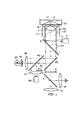
図7に示すように、本実施の形態では、新たに焦点検出光源系である焦点検出光源60と、コリメートレンズ61と、遮光板62と、半透過ミラー63と、焦点検出用ダイクロイックミラー69と、焦点検出装置系である焦点検出用レンズ64と、波長カット板70と、2分割検出器65とを観察光学系の光軸に対して追加している。
(Fourth embodiment)
FIG. 7 is a diagram showing a schematic configuration of a fluorescence observation apparatus according to the fourth embodiment of the present invention. In FIG. 7, the same parts as those in FIG.
As shown in FIG. 7, in the present embodiment, a focus
図7において、照明系と観察系は、第1の実施の形態に係る構成と同じである。ダイクロイックミラー3は、照射光源8からの所定波長の照明光111の波長の光を反射するとともに、照明光111の励起により標本12から発せられる波長の長い微弱な蛍光の波長を透過し、蛍光の波長よりさらに波長の長い焦点検出で用いる焦点検出光141も透過するように設定されている。
In FIG. 7, the illumination system and the observation system are the same as the configuration according to the first embodiment. The
照明系には、カバーガラス13で全反射した戻り光113が、観察光学系に漏れ出さないようになり、遮光板71が、ダイクロイックミラー3より標本側に配置される。
In the illumination system, the
焦点検出系では、生細胞にダメージを与えにくい赤外域の所定波長のレーザ光を発する焦点検出光源60、及びコリメートレンズ61を、それぞれの光軸を一致するように配置している。焦点検出光源60からのレーザ光を、コリメートレンズ61、半透過ミラー63、焦点検出光ダイクロイックミラー69、ダイクロイックミラー3を介して対物レンズ4の焦点位置で集光させるように各々が調整されている。
In the focus detection system, a focus
半透過ミラー63は、焦点検出光源60からの所定波長のレーザ光を半透過するとともに、残りの半分の光量を反射するように設定されている。
焦点検出光ダイクロイックミラー69は、蛍光の波長を透過すると共に、蛍光より波長の長い焦点検出光141を反射するように設定されている。
The
The focus detection light
焦点検出光源60からのレーザ光は、コリメートレンズ61の瞳位置に配置された遮光板62でその半分を遮光された焦点検出光141として対物レンズ4に入射され、カバーガラス13と標本12の密着面で焦点を結ぶと共に反射されて対物レンズ4の中心軸に対して焦点検出光141と軸対称な焦点検出戻り光142となる。
遮光板62は、焦点検出光の断面から見て半円形に遮光するように、円板状のガラス板の半円部分を遮光し、残りを透過させている。
The laser light from the focus
The
カバーガラス13と標本12の密着面で反射した焦点検出戻り光142は、ダイクロイックミラー3を透過し、焦点検出用ダイクロイックミラー69で反射し、半透過ミラー63でその半分の光量が反射して遮光板62で遮光され、残り半分の光量が透過する。半透過ミラー63を透過した焦点検出戻り光142は、焦点検出光軸と光軸を一致した焦点検出用レンズ64にて集光され、波長カット板70にて焦点検出光源60の波長のみを透過し、焦点検出光軸と軸を一致した2分割検出器65の中心の分割部で焦点を結ぶ。このときの2分割検出器65の集光面66では、2分割検出器65の両検出素子にまたがった小さな集光光が観察される。
2分割検出器65の分割面は、光軸と平行でかつ焦点検出光141と焦点検出戻り光142の分割ラインを含む面と同じ面で構成される。
The focus detection return light 142 reflected by the contact surface between the
The split surface of the two-
これにより、カバーガラス13と標本12の密着面に対物レンズ4の焦点が合った状態を検出できる。
As a result, it is possible to detect a state in which the
図8はカバーガラス13が下方向に動いたとき、焦点検出光141として対物レンズ4に入射されるレーザ光は、カバーガラス13と標本12の密着面で焦点を結ばずに反射して対物レンズ4を透過してもコリメータ光ではない焦点検出戻り光143となる。焦点検出戻り光143は2分割検出器65まで導かれ、2分割検出器65の中心より偏った位置に集光しない状態のまま到達する。したがって2分割検出器65の集光面66では、2分割検出器65の片側素子に偏った大きなボケ光67が観察される。逆に図9のようにカバーガラス13が上方向に動いたときは、カバーガラス13が下方向に動いたときの2分割検出器65の検出素子とは反対の素子に偏った大きなボケ光68が観察される。
In FIG. 8, when the
以上より焦点検出器の集光面にて両検出素子にまたがった小さな集光光が観察できるように対物レンズを光軸方向に調整する事で焦点調整を行う。 As described above, the focus adjustment is performed by adjusting the objective lens in the optical axis direction so that small condensed light straddling both detection elements can be observed on the condensing surface of the focus detector.
本実施の形態によれば、蛍光像を観察しながら常に対物レンズの焦点位置を検出することができる。また照明光111と焦点検出光141の光源が異なるため、焦点検出光141に赤外光などを用い、生細胞などの標本に与えるダメージを少なくする事ができる。また焦点検出においても、2分割検出器65の集光面のどちらに焦点検出戻り光142が到達しているかで、カバーガラス13が焦点面の上方向にあるのか下方向にあるのか判断できるため、焦点調整時にカバーガラス13の移動方向をこれだけで判断する事ができる。さらに、照明光111のカバーガラス13への入射角を変えてエバネッセント光17の浸み出し深さを変えても、焦点検出はまったく別の光源でおこなっているため焦点検出に影響が出ない。また第1の実施の形態と同様に、顕微鏡などが熱変形をおこしても、長時間にわたり焦点を合わせたまま観察を続けることができる。さらに2分割検出器65における焦点一致の位置をオフセットすることで、対物レンズ4の焦点位置がカバーガラス13と標本12の密着面から離れていても像を観察しながら焦点検出が行える。
According to the present embodiment, it is possible to always detect the focal position of the objective lens while observing the fluorescent image. Further, since the light sources of the
(第5の実施の形態)
図10は、本発明の第5の実施の形態にかかる蛍光観察装置の概略構成を示す図である。図10において、図1と同じ部分には同じ符号を付している。
(Fifth embodiment)
FIG. 10 is a diagram showing a schematic configuration of a fluorescence observation apparatus according to the fifth embodiment of the present invention. 10, the same parts as those in FIG. 1 are denoted by the same reference numerals.
図10において、1は顕微鏡本体で、この顕微鏡本体1は、一般的な倒立型の落射蛍光顕微鏡と同様に、照明光源84、対物レンズ4、ダイクロイックミラー3、光学フィルタ6、ハーフミラー5、および光ディテクタとしての撮像素子7、焦点検出光源87、焦点検出装置89を有しており、それぞれの光軸を一致させて配置されている。照明光源84による照明光は、標本12を励起する所定波長の光のみを透過する励起フィルタ85を通って標本12を照射する。対物レンズ4は、NA(対物レンズの開口数)>n(観察標本の屈折率)の条件を満たした高い開口数を有する油浸対物レンズからなる。
In FIG. 10,
対物レンズ4の上方に標本12が配置されている。標本12は、顕微鏡本体1の図示しないステージに載置されたカバーガラス13上に密着される。このカバーガラス13は生細胞である標本12の生体活動に必要な水溶液で満たされている。この標本12は、カバーガラス13の屈折率とほぼ同じ屈折率をもつオイル15を介して対物レンズ4の焦点位置に位置されている。
A
照明光88の励起により、標本12から発せられる微弱な蛍光112は、対物レンズ4及びダイクロイックミラー3を透過し、光学フィルタ6を介してハーフミラー5に入射される。ハーフミラー5は、観察光軸に対して挿脱ができるようになっており、光軸に挿入された時には、蛍光112を分割し、一方の分割蛍光が接眼レンズ16を介して観察可能であり、他方の分割蛍光が撮像素子7に入射する。一方、ハーフミラー5が光軸から抜かれた時には、蛍光112がすべて撮像素子7に導かれる。光学フィルタ6は、ダイクロイックミラー3などとともに観察光学系を構成するものであって、特定の波長の光を選択的に通すことができる。ここでは、光学フィルタ6として、照明光88の波長の光と焦点検出光151の波長の光を遮断し、照明光88よりも波長が長い蛍光112の光を通過させるものが用いられる。標本12からの蛍光112は、光学フィルタ6を通過し、蛍光像として観察されるとともに、撮像素子7により撮像される。
The
焦点検出系は、生細胞である標本にダメージを与えにくい赤外域の所定波長のレーザ光を発する焦点検出光源87、集光レンズ86を、それぞれの光軸が一致するように配置しており、焦点検出光源87からのレーザ光を集光レンズ86及びダイクロイックミラー3を介して対物レンズ4の後ろ側焦点位置に集光させるように調整されている。
In the focus detection system, a focus
ダイクロイックミラー3は、励起光88よりも波長の長い蛍光の波長を透過し、焦点検出光源87からの赤外域の所定波長の焦点検出光151を反射するとともに、励起光88を通さないように設定されている。
ダイクロイックミラー3で反射された焦点検出光源87のレーザ光は、焦点検出光151として対物レンズ4を介して標本12に照射される。
The
The laser beam of the focus
焦点検出光151は、対物レンズ4の外周部分を通る小さい光束径で、カバーガラス13と標本12の密着面で全反射する入射角度に調整されており、カバーガラス13と標本12の密着面で全反射したときに標本12側にエバネッセント光17を生成する。エバネッセント光17は、その焦点検出光151の波長より短い距離でカバーガラス13の標本12側に局在する。焦点検出光151はカバーガラス13で全反射した後、対物レンズ4の中心軸に対して焦点検出光151と軸対称な対物レンズ4の後ろ側焦点位置で集光され、焦点検出戻り光152としてダイクロイックミラー3で反射して顕微鏡本体1の内面で遮光される。
The
エバネッセント光17が標本12に当たるとその散乱光161が発生する。散乱光161はダイクロイックミラー3で反射し、焦点検出装置89にはいる。
焦点検出装置89は、集光レンズ80、ピンホール81、フィルタ82、検出器83で構成され、各々が顕微鏡本体1の光軸と一致している。散乱光161は集光レンズ80で検出器83に集光される。集光レンズ80の瞳位置にはピンホール81が配置され、焦点を合わせたい視野中心の散乱光114以外の不要な光線を大幅にカットする。ピンホール81と検出器83の間には、赤外域の所定波長である散乱光161の波長のみを透過しそれ以外の照明光88などの波長を除去するフィルタ82が構成される。
When the evanescent light 17 hits the
The
制御部10では、位置調整部14を使って対物レンズ4を光軸方向に動かし、これにより対物レンズ4の焦点位置を光軸方向に動かすことで、散乱光161の複数の像を検出器83で取得し、その信号の強度差などを求める。この信号の強度差から、信号強度が最大になる状態が標本12と対物レンズ4の焦点位置が重なる状態であるとして位置制御部14を制御して対物レンズ4を信号強度が最大になる位置まで光軸方向に動かす。
In the
本実施の形態によれば、数十ナノメートル〜数百ナノメートルという非常に薄いエバネッセント光17の領域に存在する標本12の一部分から発する散乱光161の像を使った、焦点検出と焦点合わせが可能となる。
散乱光161は、上記のように、数十ナノメートル〜数百ナノメートルのエバネッセント光17の領域でしか発光しないため、数十ナノメートル〜数百ナノメートルという精度の焦点検出が効果として得られる。
According to the present embodiment, focus detection and focusing are performed using an image of scattered light 161 emitted from a part of the
Since the scattered light 161 emits light only in the region of the
また生物研究における生細胞内での経時変化を見るためのタイムラプスでは、長期間におよぶ観察が必要となるが、観察装置である顕微鏡は金属とガラスの集合体であり、例えば実験を行う部屋の内部温度が僅かに変化しただけでも顕微鏡が熱変形し、ピント位置がずれるという問題が発生しており、特に、数十から数百nmといった微小領域を観察するエバネッセント光を利用した蛍光観察では、大きな問題となっている。しかしこの実施の形態では、観察している標本の散乱光を使って焦点検出を行うため、顕微鏡などが熱変形をおこしても、長時間にわたり焦点を合わせたまま観察を続けることができる。また焦点を合わせたい部分の像のみをピンホール81で選択するため、焦点とは関係ない像を除去し、焦点検出の精度を上げることができる。
In addition, in a time lapse to see changes over time in living cells in biological research, observation over a long period of time is required, but the microscope, which is an observation device, is an aggregate of metal and glass, for example, in the room where the experiment is performed. Even with a slight change in internal temperature, the microscope is thermally deformed and the focus position is shifted. In particular, in fluorescence observation using evanescent light for observing a minute region such as tens to hundreds of nanometers, It has become a big problem. However, in this embodiment, since focus detection is performed using the scattered light of the specimen being observed, observation can be continued with the focus kept on for a long time even if the microscope or the like undergoes thermal deformation. In addition, since only an image of a portion to be focused is selected by the
本発明は、上記各実施の形態に限ることなく、その他、実施段階ではその要旨を逸脱しない範囲で種々の変形を実施し得ることが可能である。例えば、上記の各実施の形態では、焦点検出方法を個別に述べたが、適宜組み合わせることができることはもちろんである。さらに、上記各実施形態には、種々の段階の発明が含まれており、開示される複数の構成要件における適宜な組合せにより種々の発明が抽出され得る。 The present invention is not limited to the above-described embodiments, and various modifications can be made without departing from the scope of the invention at the stage of implementation. For example, in each of the above embodiments, the focus detection methods have been described individually, but it is needless to say that they can be combined as appropriate. Further, the above embodiments include inventions at various stages, and various inventions can be extracted by appropriately combining a plurality of disclosed constituent elements.
また、例えば各実施形態に示される全構成要件から幾つかの構成要件が削除されても、発明が解決しようとする課題の欄で述べた課題が解決でき、発明の効果で述べられている効果が得られる場合には、この構成要件が削除された構成が発明として抽出され得る。 In addition, for example, even if some structural requirements are deleted from all the structural requirements shown in each embodiment, the problem described in the column of the problem to be solved by the invention can be solved, and the effect described in the effect of the invention Can be obtained as an invention.
1…顕微鏡本体
2…照明部
3…ダイクロイックミラー
4…対物レンズ
5…ハーフミラー
6…光学フィルタ
7…撮像素子
8…照射光源
9…集光レンズ
10…制御部
12…標本
13…カバーガラス
14…位置制御部
15…オイル
16…接眼レンズ
17…エバネッセント光
18…撮像レンズ
30…集光レンズ
31…検出器
32…カバーガラス面
36…エバネッセント光
39…ピンホール
40…光検出器
41…集光ポイント検出器
50…焦点検出用レンズ
52…遮光板
53…焦点検出用レンズ
54…2分割検出器
55…集光面
60…焦点検出光源
61…コリメートレンズ
62…遮光板
63…半透過ミラー
64…焦点検出用レンズ
65…分割検出器
66…集光面
67…ボケ光
69…焦点検出用ダイクロイックミラー
80…集光レンズ
81…ピンホール
82…フィルタ
83…検出器
84…照明光源
85…励起フィルタ
86…集光レンズ
87…焦点検出光源
89…焦点検出装置
DESCRIPTION OF
Claims (11)
前記標本の屈折率とは異なる屈折率をもち、前記標本を載置する透明部材と、
前記対物レンズの外周部分を通して、前記標本と前記透明部材との境界面で全反射するように照明光を照射する照明光源と、
前記対物レンズと撮像素子との間に配置された焦点検出用のダイクロイックミラーと、
前記ダイクロイックミラーのうち前記境界面からの反射光を反射させる反射面側に配置された半透過ミラーと、
前記半透過ミラーのうち前記境界面からの反射光を反射させる反射面側に設けられ、焦点検出用の検出光を照射する焦点検出光源と、
前記検出光をその光束の断面方向で半分に遮光する遮光板と、
前記半透過ミラーのうち前記境界面からの反射光を透過させる透過面側に設けられる焦点検出用の検出器と、
前記ダイクロイックミラーと前記検出器の間に設けられ、前記焦点検出光の波長のみを透過させるフィルタと、を備え、
前記検出器が受光した前記反射光の検出結果に基づいて、前記境界面に対するオートフォーカスを行うことを特徴とする焦点検出装置。 An objective lens for observing the specimen;
A transparent member having a refractive index different from the refractive index of the sample, and placing the sample;
An illumination light source that irradiates illumination light so as to be totally reflected at a boundary surface between the specimen and the transparent member through an outer peripheral portion of the objective lens;
A dichroic mirror for focus detection disposed between the objective lens and the image sensor;
A transflective mirror disposed on the reflective surface side that reflects the reflected light from the boundary surface of the dichroic mirror;
A focus detection light source that is provided on the reflective surface side that reflects the reflected light from the boundary surface of the semi-transmissive mirror and irradiates detection light for focus detection;
A light shielding plate that shields the detection light in half in the cross-sectional direction of the luminous flux;
A focus detection detector provided on the transmissive surface side that transmits the reflected light from the boundary surface of the semi-transmissive mirror ;
The dichroic mirror and is arranged between the detector, and a filter which makes transmitting only the wavelength of the focus detection light,
A focus detection apparatus that performs autofocus on the boundary surface based on a detection result of the reflected light received by the detector.
前記標本の屈折率とは異なる屈折率をもち、前記標本を載置する透明部材と、
前記対物レンズの外周部分を通して、前記標本と前記透明部材との境界面で全反射するように照明光を照射する照明光源と、
前記対物レンズと撮像素子との間に配置された焦点検出用のダイクロイックミラーと、
前記ダイクロイックミラーのうち前記境界面からの反射光を反射させる反射面側に配置された半透過ミラーと、
前記半透過ミラーのうち前記境界面からの反射光を透過させる透過面側に設けられ、焦点検出用の検出光を照射する焦点検出光源と、
前記検出光をその光束の断面方向で半分に遮光する遮光板と、
前記半透過ミラーのうち前記境界面からの反射光を反射させる反射面側に設けられる焦点検出用の検出器と、
前記ダイクロイックミラーと前記検出器の間に設けられ、前記焦点検出光の波長のみを透過するフィルタと、を備え、
前記検出器が受光した前記反射光の検出結果に基づいて、前記境界面に対するオートフォーカスを行うことを特徴とする焦点検出装置。 An objective lens for observing the specimen;
A transparent member having a refractive index different from the refractive index of the sample, and placing the sample;
An illumination light source that irradiates illumination light so as to be totally reflected at a boundary surface between the specimen and the transparent member through an outer peripheral portion of the objective lens;
A dichroic mirror for focus detection disposed between the objective lens and the image sensor;
A transflective mirror disposed on the reflective surface side that reflects the reflected light from the boundary surface of the dichroic mirror;
A focus detection light source that is provided on the transmission surface side that transmits the reflected light from the boundary surface of the semi-transmission mirror, and irradiates detection light for focus detection;
A light shielding plate that shields the detection light in half in the cross-sectional direction of the luminous flux;
A focus detection detector provided on a reflective surface side that reflects reflected light from the boundary surface of the semi-transmissive mirror ;
A filter provided between the dichroic mirror and the detector and transmitting only the wavelength of the focus detection light; and
A focus detection apparatus that performs autofocus on the boundary surface based on a detection result of the reflected light received by the detector.
前記標本の屈折率とは異なる屈折率をもち、前記標本を載置する透明部材と、
前記対物レンズを介して前記標本と前記透明部材との境界面で全反射するように前記対物レンズの外周部分を通して照明光を投光する照明光学系と、
励起された前記標本が発する微弱な蛍光を観察する観察光学系と、
前記対物レンズを介して前記境界面にオートフォーカス用の焦点検出光を投光する焦点検出光学系と、を備え、
前記焦点検出光学系は、
前記観察光学系の光路上に設けられるダイクロイックミラーと、
前記ダイクロイックミラーを通して前記境界面に焦点検出光を出射する焦点検出光源と、
前記ダイクロイックミラーのうち前記境界面からの反射光を反射させる反射面側に配置され、前記境界面からの反射光を透過及び反射させることで2つの光路に分岐させる半透過ミラーと、
前記焦点検出光源と前記半透過ミラーとの間に配置され、前記焦点検出光をその断面方向で半円形に遮光する遮光板と、
前記焦点検出光のうち前記境界面からの反射光を集光する結像レンズと、
前記半透過ミラーによって分岐された光路上に設けられ、前記結像レンズによって結像される前記焦点検出光を観察可能に配置された検出器と、を有し、
前記検出器が受光した反射光の検出結果に基づいて、前記境界面に対するオートフォーカスを行うとともに、前記境界面で全反射した照明光により生じるエバネッセント光に基づいて前記標本の蛍光像を観察することを特徴とする蛍光観察装置。 An objective lens for observing the specimen;
A transparent member having a refractive index different from the refractive index of the sample, and placing the sample ;
An illumination optical system that projects illumination light through an outer peripheral portion of the objective lens so as to be totally reflected at a boundary surface between the specimen and the transparent member via the objective lens;
An observation optical system for observing weak fluorescence emitted by the excited specimen;
A focus detection optical system that projects focus detection light for autofocus on the boundary surface through the objective lens, and
The focus detection optical system includes:
A dichroic mirror provided on the optical path of the observation optical system;
A focus detection light source for emitting focus detection light to the boundary surface through the dichroic mirror;
A semi-transparent mirror that is arranged on the reflective surface side that reflects the reflected light from the boundary surface of the dichroic mirror, and is branched into two optical paths by transmitting and reflecting the reflected light from the boundary surface ;
A light-shielding plate that is disposed between the focus detection light source and the semi-transmissive mirror and shields the focus detection light in a semicircular shape in a cross-sectional direction;
An imaging lens that collects reflected light from the boundary surface of the focus detection light , and
A detector provided on an optical path branched by the semi-transmissive mirror and disposed so that the focus detection light imaged by the imaging lens can be observed ;
Performing autofocus on the boundary surface based on the detection result of the reflected light received by the detector, and observing a fluorescent image of the sample based on evanescent light generated by illumination light totally reflected on the boundary surface A fluorescence observation apparatus characterized by the above.
Priority Applications (3)
| Application Number | Priority Date | Filing Date | Title |
|---|---|---|---|
| JP2005012824A JP4932162B2 (en) | 2005-01-20 | 2005-01-20 | Focus detection device and fluorescence observation device using the same |
| US11/328,028 US7304282B2 (en) | 2005-01-20 | 2006-01-09 | Focus detection device and fluorescent observation device using the same |
| US11/876,676 US7612316B2 (en) | 2005-01-20 | 2007-10-22 | Focus detection device and fluorescent observation device using the same |
Applications Claiming Priority (1)
| Application Number | Priority Date | Filing Date | Title |
|---|---|---|---|
| JP2005012824A JP4932162B2 (en) | 2005-01-20 | 2005-01-20 | Focus detection device and fluorescence observation device using the same |
Related Child Applications (1)
| Application Number | Title | Priority Date | Filing Date |
|---|---|---|---|
| JP2008036253A Division JP5289792B2 (en) | 2008-02-18 | 2008-02-18 | Focus detection device and fluorescence observation device using the same |
Publications (3)
| Publication Number | Publication Date |
|---|---|
| JP2006201465A JP2006201465A (en) | 2006-08-03 |
| JP2006201465A5 JP2006201465A5 (en) | 2008-03-06 |
| JP4932162B2 true JP4932162B2 (en) | 2012-05-16 |
Family
ID=36682903
Family Applications (1)
| Application Number | Title | Priority Date | Filing Date |
|---|---|---|---|
| JP2005012824A Expired - Fee Related JP4932162B2 (en) | 2005-01-20 | 2005-01-20 | Focus detection device and fluorescence observation device using the same |
Country Status (2)
| Country | Link |
|---|---|
| US (2) | US7304282B2 (en) |
| JP (1) | JP4932162B2 (en) |
Families Citing this family (13)
| Publication number | Priority date | Publication date | Assignee | Title |
|---|---|---|---|---|
| EP1678544A1 (en) * | 2003-09-25 | 2006-07-12 | Leica Microsystems CMS GmbH | Method for analysing a sample and microscope for evanescently illuminating the sample |
| JP5087745B2 (en) * | 2005-09-26 | 2012-12-05 | 国立大学法人浜松医科大学 | Microscopic cell observation / inspection system using multiple observation techniques |
| JP4663602B2 (en) | 2006-08-14 | 2011-04-06 | オリンパス株式会社 | Automatic focusing device, microscope and automatic focusing method |
| CN101583895B (en) * | 2007-01-19 | 2012-09-05 | 株式会社尼康 | Focal point detecting apparatus and microscope |
| JP2008276070A (en) * | 2007-05-02 | 2008-11-13 | Olympus Corp | Magnifying image pickup apparatus |
| JP5111608B2 (en) * | 2008-07-25 | 2013-01-09 | 株式会社日立ハイテクノロジーズ | Total reflection fluorescence observation system |
| US7883276B2 (en) * | 2008-10-14 | 2011-02-08 | Sonosite, Inc. | Optical transmission coupling |
| CN102483509B (en) | 2009-07-13 | 2015-04-22 | 株式会社尼康 | Three-dimensional directional drift control device and microscope device |
| TWI456254B (en) * | 2010-05-19 | 2014-10-11 | Ind Tech Res Inst | Fluorescence micro imaging system |
| CN103597397B (en) * | 2011-01-12 | 2016-10-26 | Idea机器显影设计及生产有限公司 | Compact microscopy system and method |
| WO2015064098A1 (en) * | 2013-10-30 | 2015-05-07 | 株式会社ニコン | Total reflection microscope |
| EP3355038B1 (en) * | 2017-01-25 | 2021-09-08 | Specim, Spectral Imaging Oy Ltd | Imaging apparatus and operating method |
| EP3614192A1 (en) * | 2018-08-20 | 2020-02-26 | Till GmbH | Microscope device |
Family Cites Families (9)
| Publication number | Priority date | Publication date | Assignee | Title |
|---|---|---|---|---|
| JP3708632B2 (en) * | 1996-07-10 | 2005-10-19 | 株式会社コーナン・メディカル | Eye photography device |
| US6594011B1 (en) * | 2000-07-11 | 2003-07-15 | Maven Technologies, Llc | Imaging apparatus and method |
| JP2002156578A (en) * | 2000-11-20 | 2002-05-31 | Olympus Optical Co Ltd | Focus detector as well as objective lens, optical microscope or optical test apparatus having the same |
| JP2002341234A (en) * | 2001-05-17 | 2002-11-27 | Olympus Optical Co Ltd | Automatic focusing device for microscope |
| JP3995458B2 (en) * | 2001-12-07 | 2007-10-24 | オリンパス株式会社 | Total reflection fluorescence microscope |
| IL148664A0 (en) * | 2002-03-13 | 2002-09-12 | Yeda Res & Dev | Auto-focusing method and device |
| JP2003270524A (en) | 2002-03-19 | 2003-09-25 | Nikon Corp | Focus detector and microscope provided therewith, and method for detecting focus |
| JP4370554B2 (en) * | 2002-06-14 | 2009-11-25 | 株式会社ニコン | Autofocus device and microscope with autofocus |
| DE10309269B4 (en) * | 2003-03-03 | 2005-06-02 | Till Photonics Gmbh | Device for Total Internal Reflection Microscopy |
-
2005
- 2005-01-20 JP JP2005012824A patent/JP4932162B2/en not_active Expired - Fee Related
-
2006
- 2006-01-09 US US11/328,028 patent/US7304282B2/en active Active
-
2007
- 2007-10-22 US US11/876,676 patent/US7612316B2/en not_active Expired - Fee Related
Also Published As
| Publication number | Publication date |
|---|---|
| US7304282B2 (en) | 2007-12-04 |
| US20080179491A1 (en) | 2008-07-31 |
| US20060157637A1 (en) | 2006-07-20 |
| JP2006201465A (en) | 2006-08-03 |
| US7612316B2 (en) | 2009-11-03 |
Similar Documents
| Publication | Publication Date | Title |
|---|---|---|
| JP4932162B2 (en) | Focus detection device and fluorescence observation device using the same | |
| CN102768015B (en) | Fluorescence response follow-up pinhole microscopic confocal measuring device | |
| EP3368887B1 (en) | Method with transillumination-based autofocusing for photoluminescence imaging | |
| JP6241858B2 (en) | Confocal microscope | |
| JP7037277B2 (en) | Observation device | |
| JP5286774B2 (en) | Microscope device and fluorescent cube used therefor | |
| JP2006201465A5 (en) | ||
| US7948629B2 (en) | Microscope and method for total internal reflection-microscopy | |
| JP5655617B2 (en) | microscope | |
| JP5107003B2 (en) | Evanescent wave generator and observation apparatus using the same | |
| EP2458420B1 (en) | Microscope | |
| JP2003270524A (en) | Focus detector and microscope provided therewith, and method for detecting focus | |
| US9372330B2 (en) | Inverted microscope system | |
| JP5289792B2 (en) | Focus detection device and fluorescence observation device using the same | |
| US6940641B2 (en) | Fluorescence observation apparatus | |
| JP2010091679A (en) | Microscope apparatus, and fluorescence cube used for the same | |
| US20220326502A1 (en) | Apparatuses, systems and methods for solid immersion meniscus lenses | |
| JP2012212018A (en) | Focal point maintenance device and microscope device | |
| JP2007293210A (en) | Imaging device | |
| US7382530B2 (en) | Method for the adjustment of a light source in a microscope | |
| JP2006309088A (en) | Highly precise measurement method of microscope focusing position | |
| JP5307868B2 (en) | Total reflection microscope | |
| JP3908022B2 (en) | Fluorescence observation equipment | |
| JP2005140956A (en) | Focal point detection device and fluorescent microscope | |
| JP2009145102A (en) | Evanescent wave generator and observation apparatus using the same |
Legal Events
| Date | Code | Title | Description |
|---|---|---|---|
| A521 | Request for written amendment filed |
Free format text: JAPANESE INTERMEDIATE CODE: A523 Effective date: 20080118 |
|
| A621 | Written request for application examination |
Free format text: JAPANESE INTERMEDIATE CODE: A621 Effective date: 20080118 |
|
| A977 | Report on retrieval |
Free format text: JAPANESE INTERMEDIATE CODE: A971007 Effective date: 20110111 |
|
| A131 | Notification of reasons for refusal |
Free format text: JAPANESE INTERMEDIATE CODE: A131 Effective date: 20110301 |
|
| A521 | Request for written amendment filed |
Free format text: JAPANESE INTERMEDIATE CODE: A523 Effective date: 20110502 |
|
| TRDD | Decision of grant or rejection written | ||
| A01 | Written decision to grant a patent or to grant a registration (utility model) |
Free format text: JAPANESE INTERMEDIATE CODE: A01 Effective date: 20120207 |
|
| A01 | Written decision to grant a patent or to grant a registration (utility model) |
Free format text: JAPANESE INTERMEDIATE CODE: A01 |
|
| A61 | First payment of annual fees (during grant procedure) |
Free format text: JAPANESE INTERMEDIATE CODE: A61 Effective date: 20120215 |
|
| R151 | Written notification of patent or utility model registration |
Ref document number: 4932162 Country of ref document: JP Free format text: JAPANESE INTERMEDIATE CODE: R151 |
|
| FPAY | Renewal fee payment (event date is renewal date of database) |
Free format text: PAYMENT UNTIL: 20150224 Year of fee payment: 3 |
|
| S531 | Written request for registration of change of domicile |
Free format text: JAPANESE INTERMEDIATE CODE: R313531 |
|
| R350 | Written notification of registration of transfer |
Free format text: JAPANESE INTERMEDIATE CODE: R350 |
|
| R250 | Receipt of annual fees |
Free format text: JAPANESE INTERMEDIATE CODE: R250 |
|
| R250 | Receipt of annual fees |
Free format text: JAPANESE INTERMEDIATE CODE: R250 |
|
| R250 | Receipt of annual fees |
Free format text: JAPANESE INTERMEDIATE CODE: R250 |
|
| R250 | Receipt of annual fees |
Free format text: JAPANESE INTERMEDIATE CODE: R250 |
|
| S111 | Request for change of ownership or part of ownership |
Free format text: JAPANESE INTERMEDIATE CODE: R313111 |
|
| R371 | Transfer withdrawn |
Free format text: JAPANESE INTERMEDIATE CODE: R371 |
|
| S111 | Request for change of ownership or part of ownership |
Free format text: JAPANESE INTERMEDIATE CODE: R313111 |
|
| LAPS | Cancellation because of no payment of annual fees | ||
| R371 | Transfer withdrawn |
Free format text: JAPANESE INTERMEDIATE CODE: R371 |