EP2107385B1 - State estimating device for secondary battery - Google Patents
State estimating device for secondary battery Download PDFInfo
- Publication number
- EP2107385B1 EP2107385B1 EP08722090.1A EP08722090A EP2107385B1 EP 2107385 B1 EP2107385 B1 EP 2107385B1 EP 08722090 A EP08722090 A EP 08722090A EP 2107385 B1 EP2107385 B1 EP 2107385B1
- Authority
- EP
- European Patent Office
- Prior art keywords
- current
- state
- battery
- secondary battery
- charge
- Prior art date
- Legal status (The legal status is an assumption and is not a legal conclusion. Google has not performed a legal analysis and makes no representation as to the accuracy of the status listed.)
- Expired - Fee Related
Links
- 230000014509 gene expression Effects 0.000 claims description 271
- 239000011149 active material Substances 0.000 claims description 114
- 238000009792 diffusion process Methods 0.000 claims description 70
- 238000003487 electrochemical reaction Methods 0.000 claims description 63
- 239000008151 electrolyte solution Substances 0.000 claims description 32
- 239000000463 material Substances 0.000 claims description 32
- 239000003990 capacitor Substances 0.000 claims description 29
- 238000006243 chemical reaction Methods 0.000 claims description 29
- 239000000376 reactant Substances 0.000 claims description 24
- 238000004364 calculation method Methods 0.000 claims description 14
- 238000009826 distribution Methods 0.000 claims description 13
- 238000009825 accumulation Methods 0.000 claims description 11
- 239000010416 ion conductor Substances 0.000 claims description 2
- 229910052744 lithium Inorganic materials 0.000 description 53
- WHXSMMKQMYFTQS-UHFFFAOYSA-N Lithium Chemical compound [Li] WHXSMMKQMYFTQS-UHFFFAOYSA-N 0.000 description 51
- 229910001416 lithium ion Inorganic materials 0.000 description 24
- HBBGRARXTFLTSG-UHFFFAOYSA-N Lithium ion Chemical compound [Li+] HBBGRARXTFLTSG-UHFFFAOYSA-N 0.000 description 15
- 238000010586 diagram Methods 0.000 description 15
- 238000000034 method Methods 0.000 description 13
- 230000001186 cumulative effect Effects 0.000 description 12
- 238000007599 discharging Methods 0.000 description 12
- 230000006870 function Effects 0.000 description 12
- 230000010287 polarization Effects 0.000 description 7
- 238000003411 electrode reaction Methods 0.000 description 5
- 230000007423 decrease Effects 0.000 description 4
- 230000001419 dependent effect Effects 0.000 description 4
- 230000008569 process Effects 0.000 description 4
- 230000003247 decreasing effect Effects 0.000 description 3
- 238000002474 experimental method Methods 0.000 description 3
- PXHVJJICTQNCMI-UHFFFAOYSA-N Nickel Chemical compound [Ni] PXHVJJICTQNCMI-UHFFFAOYSA-N 0.000 description 2
- 230000006399 behavior Effects 0.000 description 2
- 238000012790 confirmation Methods 0.000 description 2
- 230000000694 effects Effects 0.000 description 2
- 230000001771 impaired effect Effects 0.000 description 2
- 150000002641 lithium Chemical group 0.000 description 2
- 238000012545 processing Methods 0.000 description 2
- RYGMFSIKBFXOCR-UHFFFAOYSA-N Copper Chemical compound [Cu] RYGMFSIKBFXOCR-UHFFFAOYSA-N 0.000 description 1
- UFHFLCQGNIYNRP-UHFFFAOYSA-N Hydrogen Chemical compound [H][H] UFHFLCQGNIYNRP-UHFFFAOYSA-N 0.000 description 1
- 230000003044 adaptive effect Effects 0.000 description 1
- XAGFODPZIPBFFR-UHFFFAOYSA-N aluminium Chemical compound [Al] XAGFODPZIPBFFR-UHFFFAOYSA-N 0.000 description 1
- 229910052782 aluminium Inorganic materials 0.000 description 1
- 238000004458 analytical method Methods 0.000 description 1
- 230000008901 benefit Effects 0.000 description 1
- 239000002131 composite material Substances 0.000 description 1
- 229910052802 copper Inorganic materials 0.000 description 1
- 239000010949 copper Substances 0.000 description 1
- 238000005516 engineering process Methods 0.000 description 1
- 229910052739 hydrogen Inorganic materials 0.000 description 1
- 239000001257 hydrogen Substances 0.000 description 1
- 238000002847 impedance measurement Methods 0.000 description 1
- 238000012986 modification Methods 0.000 description 1
- 230000004048 modification Effects 0.000 description 1
- 229910052759 nickel Inorganic materials 0.000 description 1
- 230000003252 repetitive effect Effects 0.000 description 1
- 239000011347 resin Substances 0.000 description 1
- 229920005989 resin Polymers 0.000 description 1
- 230000004044 response Effects 0.000 description 1
- 230000001131 transforming effect Effects 0.000 description 1
Images


Classifications
-
- H—ELECTRICITY
- H01—ELECTRIC ELEMENTS
- H01M—PROCESSES OR MEANS, e.g. BATTERIES, FOR THE DIRECT CONVERSION OF CHEMICAL ENERGY INTO ELECTRICAL ENERGY
- H01M10/00—Secondary cells; Manufacture thereof
- H01M10/42—Methods or arrangements for servicing or maintenance of secondary cells or secondary half-cells
- H01M10/48—Accumulators combined with arrangements for measuring, testing or indicating the condition of cells, e.g. the level or density of the electrolyte
-
- G—PHYSICS
- G01—MEASURING; TESTING
- G01R—MEASURING ELECTRIC VARIABLES; MEASURING MAGNETIC VARIABLES
- G01R31/00—Arrangements for testing electric properties; Arrangements for locating electric faults; Arrangements for electrical testing characterised by what is being tested not provided for elsewhere
- G01R31/36—Arrangements for testing, measuring or monitoring the electrical condition of accumulators or electric batteries, e.g. capacity or state of charge [SoC]
- G01R31/367—Software therefor, e.g. for battery testing using modelling or look-up tables
-
- G—PHYSICS
- G01—MEASURING; TESTING
- G01R—MEASURING ELECTRIC VARIABLES; MEASURING MAGNETIC VARIABLES
- G01R31/00—Arrangements for testing electric properties; Arrangements for locating electric faults; Arrangements for electrical testing characterised by what is being tested not provided for elsewhere
- G01R31/36—Arrangements for testing, measuring or monitoring the electrical condition of accumulators or electric batteries, e.g. capacity or state of charge [SoC]
- G01R31/382—Arrangements for monitoring battery or accumulator variables, e.g. SoC
- G01R31/3842—Arrangements for monitoring battery or accumulator variables, e.g. SoC combining voltage and current measurements
-
- H—ELECTRICITY
- H01—ELECTRIC ELEMENTS
- H01M—PROCESSES OR MEANS, e.g. BATTERIES, FOR THE DIRECT CONVERSION OF CHEMICAL ENERGY INTO ELECTRICAL ENERGY
- H01M10/00—Secondary cells; Manufacture thereof
- H01M10/42—Methods or arrangements for servicing or maintenance of secondary cells or secondary half-cells
- H01M10/44—Methods for charging or discharging
-
- Y—GENERAL TAGGING OF NEW TECHNOLOGICAL DEVELOPMENTS; GENERAL TAGGING OF CROSS-SECTIONAL TECHNOLOGIES SPANNING OVER SEVERAL SECTIONS OF THE IPC; TECHNICAL SUBJECTS COVERED BY FORMER USPC CROSS-REFERENCE ART COLLECTIONS [XRACs] AND DIGESTS
- Y02—TECHNOLOGIES OR APPLICATIONS FOR MITIGATION OR ADAPTATION AGAINST CLIMATE CHANGE
- Y02E—REDUCTION OF GREENHOUSE GAS [GHG] EMISSIONS, RELATED TO ENERGY GENERATION, TRANSMISSION OR DISTRIBUTION
- Y02E60/00—Enabling technologies; Technologies with a potential or indirect contribution to GHG emissions mitigation
- Y02E60/10—Energy storage using batteries
Definitions
- the present invention relates generally to devices estimating a state of a secondary battery and in particular to devices estimating a state of a secondary battery in accordance with a battery model allowing the secondary battery's internal state to be estimated based on an electrochemical reaction.
- a power supply system configured such that a chargeable secondary battery supplies a load with electric power and the secondary battery can also be charged as required while the load is in operation.
- hybrid vehicles, electric vehicles and the like including as a driving force source an electric motor driven by a secondary battery have such power supply systems mounted therein.
- the secondary battery's stored electric power is used as electric power driving the electric motor serving as the driving force source, and electric power generated when the electric motor regenerates electric power, electric power generated by an electric power generator as an engine rotates, and the like charge the secondary battery.
- SOC state of charge
- the secondary battery For hybrid vehicles in particular, it is necessary that the secondary battery have its state of charge controlled to be approximately intermediate between its fully charged state (100%) and its completely uncharged state (0%), i.e., 50 to 60%, so that the secondary battery can receive regenerated electric power and also supply the electric motor with electric power immediately as required.
- over-discharging or overcharging a secondary battery may degrade the battery's performance and reduce its life.
- an intermediate SOC is set as a target for control, as described above, and a secondary battery is accordingly charged/discharged repeatedly in its use
- the secondary battery's amount of charge is monitored sequentially and charging/discharging the secondary battery is controlled to restrict overcharging/over-discharging the secondary battery.
- patent document 1 Japanese Patent Laying-open No. 2005-37230 discloses a technique to estimate from a value of a cumulative current of a battery how the battery varies in SOC.
- patent document 1 describes that a current sensor measures the battery's current and in parallel therewith an operation is performed to obtain an estimated charged/discharged current, and an operation is performed to obtain the battery's current to obtain a measured SOC, while the estimated charged/discharged current is accumulated to obtain an estimated SOC.
- a difference between the estimated SOC and the measured SOC is obtained and how the difference in SOC varies with time is accumulated to obtain a cumulative SOC value, and when the cumulative SOC value is equal to or larger than a predetermined value in comparison with an initial value, that the battery is degraded is detected.
- patent document 2 Japanese Patent Laying-open No. 2004-178848 discloses a device estimating a state of charge of a secondary battery, that is configured such that an adaptive digital filter is used to estimate no load voltage (OCV) from a value of the secondary battery's current as measured and that of a terminal's voltage as measured and a state of charge is estimated in accordance with a previously obtained relationship between no load voltage and a state of charge.
- OCV no load voltage
- This device estimating a state of charge of a secondary battery employs a low pass filter as the secondary battery's internal equivalent circuit model, and it is thus difficult to precisely estimate the secondary battery's internal behavior involving the diffusion of a reaction involved material contributing to an electrochemical reaction.
- non-patent document 1 W.B. Gu and C.Y. Wang, THERMAL-ELECTROCHEMICAL COUPLED MODELING OF A LITHIUM-ION CELL, ECS Proceedings Vol. 99-25 (1), 2000, ECS, pp. 748-762 ) discusses a battery model employing an expression of an electrochemical reaction internal to a lithium battery and reports that a characteristic can be represented with high precision in comparison with an actual battery.
- non-patent document 1 indicates that the secondary battery's no load voltage depends on a local SOC obtained at an electrode's interface with an electrolytic solution (a surface of an active material) and as a result the battery's voltage in relaxation is governed by diffusion of lithium depending on how lithium is distributed in concentration in an active material.
- the document discloses that the diffusion of the reaction involved material (lithium) in the active material is governed by a diffusion equation of spherical coordinates handling the active material as a sphere and a diffusion rate of a material governed by a diffusion coefficient in a diffusion process.
- the secondary battery's internal state will estimated by a macro equivalent model with the secondary battery's voltage and current serving as an input and an output, and it is difficult to provide estimation with high precision based on the secondary battery's internal state involving the reaction involved material's diffusion.
- non-patent document 1 if the reaction involved material's diffusion is represented by a diffusion equation, as based on the battery's internal electrochemical reaction, and the battery's open circuit voltage depends on a local SOC obtained at an electrode-electrolytic solution interface (a surface of an active material), then while the battery model will be non-linear, the battery's state can be estimated with higher precision.
- an analysis provided in accordance with the model disclosed in non-patent document 1 involves a significantly large operating load and it is thus difficult for example to mount it in an actual device and estimate a state on line when the secondary battery is used.
- the present invention has been made to overcome such disadvantage as described above, and it contemplates a device estimating a state of a secondary battery, that employs a battery model allowing the battery's internal state to be estimated from an electrochemical reaction and also achieving an alleviated operating load, and is thus suitable for being mounted in an actual device.
- the present device estimating a state of a secondary battery is defined by claim 1.
- the above device estimating a state of a secondary battery can estimate how a reactant material (representatively, lithium in a lithium battery) is diffused in an active material in accordance with an active material diffusion model expression and combine the active material diffusion model expression with a simplified a voltage-current relationship model expression estimating the secondary battery's current density from an open circuit voltage (OCV, which is synonymous with no load voltage) estimated from a concentration of the reactant material estimated at an interface of the active material with the electrolytic solution, the battery's voltage as measured, and a parameter value previously obtained for the secondary battery to estimate how the reactant material is distributed in concentration.
- OCV open circuit voltage
- a battery model expression can thus be implemented that allows a simplified a voltage-current relationship model expression to alleviate an operating load and a secondary battery's internal state to be estimated from an electrochemical reaction with high precision.
- the device estimating a state of a secondary battery further comprises a temperature detector, and a parameter value setting unit for setting the parameter value variably in accordance with at least the temperature of the battery.
- the temperature detector detects the temperature of the secondary battery.
- the parameter value setting unit further sets a parameter value indicative of a diffusion rate in the active material diffusion model expression variably in accordance with at least the temperature of the battery.
- a parameter value used in a battery model expression can be set variably in accordance with the secondary battery's temperature.
- a battery parameter's temperature dependence can thus be reflected to further precisely estimate the secondary battery's state.
- the voltage-current relationship model expression is configured by a linearly approximated expression indicating that the open circuit voltage minus a product of the density of the current of the battery and an electrical resistance provided per a unit area of the electrode that is served as the parameter value is a voltage equal to the voltage of the battery, and the parameter value setting unit sets the electrical resistance variably in accordance with the concentration of the reactant material obtained at the interface, as estimated by the diffusion estimation unit, and the temperature of the battery detected by the temperature detector.
- the linearly approximated expression can eliminate the necessity of performing a convergent calculation in an operation of a voltage-current relationship model expression estimating a battery's current density from the battery's voltage. This can alleviate a load of and stabilize the operation by the voltage-current relationship model expression, and a battery model expression can be implemented that is suitable for being mounted in an actual device.
- the device estimating a state of a secondary battery further comprises a current operation unit that separates the density of the current of the secondary battery in total into a first current density contributing to the electrochemical reaction and a second current density caused by a component caused in the secondary battery for an electric double layer capacitor.
- the boundary condition setting unit calculates the reaction current density at the interface, as based on the first current density calculated by the current operation unit, and in the voltage-current relationship model expression the overvoltage is calculated based on the first current density.
- the secondary battery's entire current component can have separated therefrom a current that flows through an electric double layer capacitor and thus does not contribute to an electrochemical reaction, and the active material diffusion model expression and the voltage-current relationship model expression can thus be operated. Estimation with improved precision can be achieved.
- the device estimating a state of a secondary battery further comprises: a temperature detector that detects a temperature of the secondary battery; and a parameter value setting unit for setting the parameter value variably in accordance with at least the temperature of the battery.
- the voltage-current relationship model expression is configured of: a linearly approximated expression indicating that a product of the first current density and a first electrical resistance provided per a unit area of the electrode that is served as the parameter value is equal to the voltage of the battery; and an expression indicating that the second current density that is served as the parameter value and flowing through the capacitor per the unit area of the electrode is a value proportional to an amount of the voltage of the battery that varies with time.
- the parameter value setting unit sets the first electrical resistance variably in accordance with the concentration of the reactant material obtained at the interface, as estimated by the diffusion estimation unit, and the temperature of the battery detected by the temperature detector, and also variably sets a capacitance per the unit area of the electrode in accordance with the temperature of the battery.
- the linearly approximated expression can eliminate the necessity of performing a convergent calculation in an operation of a voltage-current relationship model expression estimating a battery's current density from the battery's voltage. This can alleviate a load of and stabilize the operation by the voltage-current relationship model expression, and a battery model expression can be implemented that is suitable for being mounted in an actual device.
- the diffusion estimation unit has the active material diffusion model expression represented by a polar coordinate for each of the first and second electrodes.
- first and second electrodes separate active material diffusion models can be created, respectively, and for each electrode how a reactant material (e.g., lithium) diffuses can be modeled. Estimation can be done with improved precision.
- a reactant material e.g., lithium
- the diffusion estimation unit has the active material diffusion model expression represented by a polar coordinate and shared by the first and second electrodes.
- first and second electrodes can share a single active material diffusion model.
- a battery model expression can be implemented that contemplates a further alleviated operating load and is thus further suitable for being mounted in an actual device.
- the voltage-current relationship model expression is derived as based on: a voltage equation indicating a relationship between average potentials of the active material and the electrolytic solution, an average value of an overvoltage generated as the electrochemical reaction is caused at the interface, and the open circuit voltage; and an electrochemical reaction expression indicating a relationship between the density of the current of the battery and the average value of the overvoltage.
- the voltage-current relationship model expression is derived by simplifying a distribution in potential of the active material in the electrode and the electrolytic solution to a quadric, and in that condition, obtaining the average potentials of the active material and the electrolytic solution.
- the voltage-current relationship model expression is derived as based on a voltage equation indicating a relationship between average potentials of the active material and the electrolytic solution, an overvoltage generated as the electrochemical reaction is caused, and the open circuit voltage; and furthermore, an electrochemical reaction expression indicating a relationship between the density of the current of the battery and the average value of the overvoltage.
- the device estimating a state of a secondary battery further comprises an average concentration calculation unit and a first state-of-charge estimation unit.
- the average concentration calculation unit calculates an average concentration of the reactant material in the active material, as based on the distribution in concentration of the reactant material estimated by the diffusion estimation unit.
- the first state-of-charge estimation unit estimates a state of charge of the secondary battery in accordance with a previously obtained correspondence relationship between the average concentration and the state of charge, as based on the average concentration calculated by the average concentration calculation unit.
- the secondary battery's state of charge can be estimated in accordance with an average concentration of the reactant material in the active material of the electrode.
- the state of charge can be estimated with high precision based on a state estimated from an electrochemical reaction caused in the secondary battery.
- the device estimating a state of a secondary battery further comprises a current detector, a second state-of-charge estimation unit, and a third state-of-charge estimation unit.
- the current detector detects a current of the secondary battery.
- the second state-of-charge estimation unit estimates an amount of variation of the state of charge of the secondary battery, as based on the current of the battery accumulated.
- the third state-of-charge estimation unit sequentially updates an estimated value of the state of charge of the secondary battery, as based on a result of estimating by the first and second state-of-charge estimation units.
- the third state-of-charge estimation unit calculates a current value of the estimated value of the state of charge by reflecting the amount of variation of the state of charge from the previous value estimated by the second state-of-charge estimation unit, and an error in state of charge between a current state of charge estimated by the first state-of-charge estimation unit and the previous value, in a previous value of the estimated value of the state of charge, on the previous value.
- the amount of variation of the state of charge is reflected with a time constant relatively smaller than that applied in reflecting the error in state of charge.
- estimating a state of charge based on a cumulative measured current value which is highly precise for short-term estimation, and estimating a state of charge based on the above described battery model, can be combined together to estimate the secondary battery's state of charge with high precision.
- the device estimating a state of a secondary battery further comprises a current detector, a second state-of-charge estimation unit, and a third state-of-charge estimation unit.
- the current detector detects a current of the secondary battery.
- the second state-of-charge estimation unit estimates an amount of variation of the state of charge of the secondary battery, as based on the current of the battery accumulated.
- the third state-of-charge estimation unit sequentially updates an estimated value of the state of charge of the secondary battery, as based on a result of estimating by the first and second state-of-charge estimation units.
- the third state-of-charge estimation unit calculates a current value of the estimated value of the state of charge by reflecting the amount of variation of the state of charge from the previous value estimated by the second state-of-charge estimation unit, and an error in state of charge between a current state of charge estimated by the first state-of-charge estimation unit and a previous value of the estimated value of the state of charge, on the previous value.
- the third state-of-charge estimation unit ceases to reflect the error in state of charge and calculates the current value of the estimated value of the state of charge.
- the battery model's estimation error can be prevented from contributing to a state of charge estimated with poor precision.
- the device estimating a state of a secondary battery further comprises an offset estimation unit that calculates an estimated value of the current of the battery, as based on the density of the current of the battery estimated by the current estimation unit, and estimates an offset error of the current detector, as based on an error of the estimated value of the current of the battery and a value detected by the current detector.
- the second state-of-charge estimation unit uses the offset error estimated by the offset estimation unit to correct the value of the current of the battery detected by the current detector, and estimates the amount of variation of the state of charge of the secondary battery, as based on an accumulation of the value detected that is corrected.
- the device estimating a state of a secondary battery further comprises a current detector, an offset estimation unit, and a state-of-charge estimation unit.
- the current detector detects a current of the secondary battery.
- the offset estimation unit calculates an estimated value of the current of the battery, as based on the density of the current of the battery estimated by the current estimation unit, and estimates an offset error of the current detector, as based on an error of the estimated value of the current of the battery and a value detected by the current detector.
- the state-of-charge estimation unit uses the offset error estimated by the offset estimation unit to correct the value of the current of the battery detected by the current detector, and estimates an amount of variation of the state of charge of the secondary battery, as based on an accumulation of the value detected that is corrected.
- the current detector's offset can be estimated from the battery's current estimated through a battery model and a measured current value with the offset corrected can be accumulated to allow a state of charge to be estimated from a cumulative current with improved precision.
- a major advantage of the present invention lies in being capable of implementing a device estimating a state of a secondary battery that employs a battery model that allows the secondary battery's internal state to be estimated from an electrochemical reaction and also achieves an alleviated operating load, and is thus suitable for being mounted in an actual device.
- Fig. 1 is a block diagram schematically illustrating an exemplary configuration of a power supply system having applied thereto a device estimating a state of a secondary battery according to an embodiment of the present invention.
- a power supply system 5 is configured of a secondary battery 10, a load 20, and a battery ECU 50 and a control device 60 configured of an electronic control unit (ECU).
- ECU electronice control unit
- Each ECU is representatively configured of a microcomputer and a memory (random access memory (RAM), read only memory (ROM), or the like) for performing a previously programmed predetermined sequence and predetermined operation.
- RAM random access memory
- ROM read only memory
- Chargeable and dischargeable secondary battery 10 is representatively implemented as a lithium ion battery, which is suitable for application to the present invention as the battery has an output characteristic varying with how a reactant material (lithium) is distributed in the battery, in an active material of an electrode in particular, in concentration.
- a reactant material lithium
- Secondary battery 10 is provided with a temperature sensor 30 measuring the battery's temperature Tb, a current sensor 32 measuring a current Ib input/output to/from secondary battery 10 (hereinafter also referred to as “the battery's current Ib"), and a voltage sensor 34 measuring an inter-terminal voltage Vb between a positive electrode and a negative electrode (hereinafter also referred to as “the battery's voltage Vb").
- Load 20 is driven by electric power output from secondary battery 10. Furthermore, it is assumed that an electric power generating/feeding element (not shown) is provided to be included in load 20 or separately from load 20 and that secondary battery 10 is chargeable with a current charged from the electric power generating/feeding element. Accordingly, when secondary battery 10 is discharged, the battery's current is positive (i.e., > 0), and when secondary battery 10 is charged, the battery's current is negative (i.e., ⁇ 0).
- Battery ECU 50 receives values detected by the group of sensors 30, 32, 34 provided for secondary battery 10 and, based thereon, follows a battery model allowing an internal state of secondary battery 10 to be estimated from an electrochemical reaction, as will be described hereinafter more specifically, to calculate an estimated state value indicative of the battery's state sequentially for each predetermined period.
- battery ECU 50 Furthermore, from the estimated state value calculated, battery ECU 50 generates battery information for restricting charging/discharging the secondary battery.
- the battery information includes an SOC (0% to 100%) indicating an charged amount (or available capacitance) relative to a fully charged state (100%), an electric power allowed to be input Win indicating an upper limit value for electric power currently permitted to be charged and an electric power allowed to be output Wout indicating an upper limit value for electric power discharged, and the like.
- Control device 60 operates in response to a request to load 20 for operation and with the battery information received from battery ECU 50 taken into consideration to limit charging/discharging secondary battery 10 to avoid overcharging or over-discharging secondary battery 10, and in that condition generates an instruction to operate load 20.
- control device 60 limits the electric power that is input/output to/from secondary battery 10 to be the electric power allowed to be input Win/the electric power allowed to be output Wout and generates the instruction to operate load 20.
- secondary battery 10 has an SOC of at most a lower limit value
- control device 60 prohibits load 20 from performing an operation consuming electric power or compulsorily initiates an operation of load 20 to generate electric power (or an operation to charge secondary battery 10).
- control device 60 compulsorily prohibits load 20 from performing the operation generating electric power.
- Fig. 2 schematically shows a configuration of the secondary battery.
- secondary battery 10 includes a negative electrode 12, a separator 14, and a positive electrode 15.
- Separator 14 is configured of resin provided between negative electrode 12 and positive electrode 15 and having an electrolytic solution permeated therein. Separator 14 corresponds to an "ion conductor" in the present invention. Furthermore, a horizontal axial coordinate x indicates a position in the electrodes' depthwise direction.
- Negative electrode 12 and positive electrode 15 are each configured of an aggregate of a spherical active material 18. In discharging, a chemical reaction is caused on an interface of active material 18 of negative electrode 12 to discharge lithium ion Li + and electron e - while on an interface of active material 18 of positive electrode 15 a chemical reaction is caused to absorb lithium ion Li + and electron e - .
- Negative electrode 12 is provided with a current collector 13 absorbing electron e - and positive electrode 15 is provided with a current collector 16 discharging electron e - .
- the negative electrode's current collector 13 is configured of copper and the positive electrode's current collector 16 is configured of aluminum.
- Current collector 13 is provided with a terminal 1 In of the negative electrode and current collector 16 is provided with a terminal 11p of the positive electrode.
- a secondary battery charging device employs a basic battery model expression indicated by primitive equations of expressions (1) to (11) indicated below. Furthermore, Fig. 3 is a list of variables and constants used in the battery model expression.
- a representation of (t) indicating a function of time, a representation of (T) indicating dependence on the battery's temperature, and a representation of ( ⁇ ) indicating dependence on a local SOC ⁇ , and the like may be omitted in the present specification.
- a symbol # added to a variable or a constant represents an average value.
- an expression (3) is established as an expression relating to a principle of conservation in density of lithium ions in the electrolytic solution.
- a diffusion equation of expression (4) and a boundary condition expression indicated by expressions (5) and (6) are applied as expressions relating to a principle of conservation in concentration of lithium in the active material.
- An expression (5) indicates a boundary condition at a center of the active material and an expression (6) indicates a boundary condition at an interface of the active material with the electrolytic solution (hereinafter also simply referred to as an "interface").
- the active material's interface has a local lithium distribution in concentration, or a local SOC ⁇ j , defined by an expression (7).
- c sej represents a concentration of lithium at the interface of the active material of the positive and negative electrodes, as indicated in an expression (8).
- c sj,max represents a lithium concentration limit in the active material.
- an expression (9) is established as an expression relating to the principle of conservation of charge in the electrolytic solution and an expression (10) is established as an expression relating to the principle of conservation of charge in the active material.
- an expression (11) is established as an expression of an electrochemical reaction caused at the active material's interface, indicating a relationship between a current density I(t) and a reaction current density j j Li .
- the primitive equations of expressions (1) to (11) are those disclosed in non-patent document 1. Exactly applying these battery model expressions to a state estimation device mounted in an actual device and estimating a secondary battery's state on line is, however, extremely difficult due to a restriction on an ECU's (battery ECU 50's) operating load and operating time. Accordingly in the present embodiment the battery model expression is simplified, as will be described hereinafter.
- negative electrode 12 and positive electrode 15 each have an electrochemical reaction uniformly. More specifically, it is assumed that each electrode 12, 15 has the reaction uniformly in a direction x. Furthermore, as it is assumed that negative electrode 12 and positive electrode 15 each internally have each active material's reaction uniformly, a single active material model will be handled in each of negative electrode 12 and positive electrode 15. Consequently, the Fig. 2 secondary battery's schematic structure is modeled as shown in Fig. 4 .
- an electrode reaction is caused at a surface of the negative electrode's active material model 18n.
- Active material model 18n thus has a lithium atom Li discharging an electron e - and thus becoming a lithium ion Li + and thus discharged to an electrolytic solution in separator 14.
- an electrode reaction caused at a surface of the positive electrode's active material model 18p allows the lithium ion Li + in the electrolytic solution to be taken in and the electron e - to be absorbed. The lithium atom Li is thus taken into the positive electrode's active material model 18p.
- an electrode reaction caused at a surface of the negative electrode's active material model 18n allows a lithium ion Li + in the electrolytic solution to be taken in and an electrode reaction caused at a surface of the positive electrode's active material model 18p allows a lithium ion Li + to be discharged to the electrolytic solution.
- each active material model 18p, 18n has a lithium concentration c s , which can be represented as a function on a radial coordinate r (r: a distance from a center of each point, r s : a radius of the active material), assuming that it is position-independent as seen circumferentially.
- ⁇ c sj r j , t ⁇ t D sj ⁇ 2 c sj ⁇ r j 2 + 2 r j ⁇ c sj ⁇ r j ⁇ c sj r j , t ⁇ r
- expression (9) which relates to the principle of conservation of charge in the electrolytic solution, is simplified to an expression (12), indicated below, by expression (3') assuming that the electrodes have an electrochemical reaction therein uniformly and that the electrolytic solution is invariable in concentration with time. More specifically, the electrolytic solution has a potential ⁇ ej approximated by a quadric of x, and an average potential ⁇ ej # in the electrolytic solution used in calculating overvoltage ⁇ j # is obtained by integrating expression (12) with respect to the electrode's thickness L j , i.e., by an expression (13) indicated below.
- an expression (14) indicated below is established from expression (12), and accordingly, the electrolytic solution's average potential ⁇ e2 # and the electrolytic solution's potential at a boundary with separator 14 will have a difference in potential, as represented by an expression (15) indicated below. Similarly, for positive electrode 15, the electrolytic solution's average potential ⁇ e1 # and the electrolytic solution's potential at a boundary with separator 14 will have a difference in potential, as represented by an expression (16) indicated below.
- expression (10) relating to the principle of conservation of charge in the active material is also simplified to an expression (17) indicated below. More specifically, the active material also has a potential ⁇ sj approximated by a quadric of x, arid an average potential ⁇ sj # in the active material used in calculating overvoltage ⁇ j # is obtained by integrating expression (17) with respect to the electrode's thickness L j , i.e., by an expression (18) indicated below. Accordingly, similarly as described for the potential in the electrolytic solution, for positive electrode 15, the active material's average potential ⁇ s1 # and the active material's potential at a boundary with an electric collector (current collector 16) have a difference in potential, as indicated below by an expression (19).
- an active material diffusion model expression (M2a) is obtained for active material models 18p and 18n at positive electrode 15 and negative electrode 12, respectively.
- model expression (M1a) on the right-hand side the first term indicates an open circuit voltage (OCV) determined by a concentration of a reactant material (lithium) that is obtained at a surface of the active material and the second term indicates overvoltage ( ⁇ 1 # - ⁇ 2 #) and the third term indicates a voltage drop attributed to the battery's current. More specifically, the secondary battery's pure direct current resistance is represented in expression (M1a) by Rd(T).
- diffusion coefficients D s1 and D s2 used as a parameter value defining a diffusion rate of the reactant material, or lithium, are temperature-dependent. Accordingly, diffusion coefficients D s1 and D s2 are set, for example in accordance with a map shown in Fig. 7 , as a variable parameter value set variably relative to the battery's temperature T detected by temperature sensor 30. As shown in Fig. 7 , diffusion coefficients D s1 and D s2 have a characteristic that relatively decreases when the battery has low temperature and that relatively increases as the battery's temperature increases.
- diffusion coefficients D s1 and D s2 may be dependent not only on temperature but also local SOC ⁇ , and in that case, a two dimensional map is previously prepared that sets these diffusion coefficients as a parameter value in accordance with the battery's temperature T as detected and a local SOC ⁇ as estimated.
- open circuit voltages U 1 and U 2 also have a dependence increasing or decreasing as local SOC ⁇ decreases, as shown in Fig. 8A and Fig. 8B . Accordingly, such local SOC dependence is reflected in previously setting a map setting open circuit voltages U 1 and U 2 in expression (M1a) in accordance with local SOC ⁇ as estimated.
- exchange current densities i 01 and i 02 also have dependence on local SOC ⁇ and the battery's temperature T, and accordingly, a two dimensional map with ⁇ and T serving as arguments is previously prepared and exchange current densities i 01 and i 02 are determined as a parameter value of the battery in accordance with local SOC ⁇ currently obtained and the battery's temperature T currently obtained.
- pure direct current resistance Rd is also temperature dependent, and accordingly, the temperature dependence is reflected in previously preparing a map setting pure direct current resistance Rd as a parameter value of the battery in accordance with the battery's temperature T detected in accordance with value Tb detected by temperature sensor 30.
- Fig. 4 shows a method that employs separate active material models for negative electrode 12 and positive electrode 15, respectively.
- negative electrode 12 and positive electrode 15 may share an active material model to provide a modeling that contemplates a further alleviated operating load.
- the negative electrode 12 and positive electrode 15 active material models 18n and 18p are collectively handled as a single element. Accordingly, substituting an expression such as indicated by an expression (26) will be required, as indicated below. Expression (26) does not have the subscripted letter "j" distinguishing the positive electrode and the negative electrode.
- model expressions (M1a) and (M2a) that are further simplified to a model, i.e., expressions (M1b) and (M2b), are obtained, as indicated below.
- a battery model expression having applied thereto an active material model shared by the positive electrode and the negative electrode has current density I(t) and reaction current density j j Li in a relational expression of an expression (21') rather than (21).
- Expression (M1a) indicated above has an arcsinh term on the right-hand side at the second term indicating overvoltage. Accordingly, it is necessary to solve a non-linear expression. Accordingly, operating expression (M1a) requires a repetitive calculation, which may results in an increased operating load and in addition thereto impaired operation stability. Accordingly, expression (M1a) having the arcsinh term with a simple approximation (or a linear approximation) applied thereto, i.e., a voltage-current relationship model expression (M1c), is derived.
- reaction resistance Rr has dependence on local SOC ⁇ and the battery's temperature T with respect to exchange current densities i 01 , i 02 , as indicated above by an expression (27). Accordingly, if voltage-current relationship model expression (M1c) is used, it will also be necessary to previously prepare a map that reflects dependence on local SOC ⁇ and the battery's temperature T for reaction resistance Rr( ⁇ i , T) in accordance with a result of an experiment or the like and set the reaction resistance with reference to the map as a parameter of the battery, as appropriate.
- voltage-current relationship model expression (M1c) will be represented as a linear model expression established between the battery's voltage V(t), the battery's current density I(t), Rr( ⁇ , T) and Rd(T) serving as a parameter of the battery, and open circuit voltages U 1 , U 2 , as indicated above in an expression (28).
- expression (M1b) indicated above also has an arcsinh term on the right-hand side at the second term linearly approximated to provide an expression (M1d) as indicated below.
- expression (M1c) is also expressed as a linear model expression.
- V t U ⁇ , t + RT ⁇ a F ⁇ I t 2 L 1 a s i 0 ⁇ , t ⁇ ⁇ Rr ⁇ , T ⁇ I t ⁇ I t L 1 3 ⁇ 1 eff + L s ⁇ s eff + L 2 3 ⁇ 2 eff + L 1 3 ⁇ 1 eff + L 2 3 ⁇ 2 eff ⁇ Rd T
- Fig. 9 is a block diagram schematically illustrating a configuration of a device estimating a state of a secondary battery according to the first embodiment of the present invention.
- Fig. 9 shows blocks, which are implemented basically by battery ECU 50 processing a program.
- a state estimation device 50# includes a diffusion estimation unit 100, an open circuit voltage estimation unit 110, a current estimation unit 120, a battery parameter value setting unit 130, and a boundary condition setting unit 140.
- Diffusion estimation unit 100 uses active material diffusion model expression (M2a) or (M2b), as based on a boundary condition set by boundary condition setting unit 140 in accordance with expressions (5') and (6'), to sequentially perform an operation to obtain a distribution in concentration of lithium in the active material by differential formula, for example. Diffusion estimation unit 100 thus estimates a distribution in concentration of lithium, and based thereon, with the outermost region's lithium concentration serving as lithium concentration c sej obtained at the interface of the material, local SOC ⁇ is set in accordance with expression (7).
- Open circuit voltage estimation unit 110 obtains in accordance with a map reflecting a characteristic indicated in Fig. 8A and Fig. 8B the positive and negative electrodes' respective open circuit voltages or an open circuit voltage of a composite of the positive electrode and the negative electrode. In Fig. 9 , these will be indicated collectively as an open circuit voltage U( ⁇ ).
- Battery parameter value setting unit 130 sets a parameter for the battery in a battery model expression that is used in accordance with the battery's temperature T detected in accordance with value Tb detected by temperature sensor 30 and the current local SOC ⁇ based on the estimation done by diffusion estimation unit 100.
- diffusion constants D s1 , D s2 , D s in model expressions (M2a), (M2b) that are used in diffusion estimation unit 100 are set in accordance with the battery's temperature T, and other than that, pure direct current resistance Rt in model expressions (M1a) to (M1d), or exchange current densities i 01 , i 02 in model expressions (M1a), (M1b) or reaction resistance Rr in model expressions (M1c), (M1d), and the like are set by battery parameter value setting unit 130.
- current estimation unit 120 Based on expressions (M1a) to (M1d), current estimation unit 120 follows any of expressions (M3a) to (M3d), as indicated below, substituting open circuit voltage U( ⁇ ) estimated by open circuit voltage estimation unit 110 and the battery's current voltage V(t) detected in accordance with value Vb detected by voltage sensor 34, to calculate the battery's current density I(t).
- h I t V t ⁇ U 1 # ⁇ 1 , t + U 2 # ⁇ 2 , t ⁇ RT ⁇ a 1 F arcsin h ⁇ I t 2 L 1 a s 1 i 01 ⁇ 1 , T , t ⁇ arcsin h I t 2 L 1 a s 2 i 02 ⁇ 2 , T , t + I t L 1 3 ⁇ 1 eff + L s 3 ⁇ s eff + L 2 3 ⁇ 2 eff + L 1 3 ⁇ 1 eff + L 2 3 ⁇ 2 eff ⁇ Rd T
- expression (M3a) corresponds to expression (M1a) solved for the battery's current density I(t). If expression (M3a), which is a nonlinear equation, is solved in Newton's method or the like, it can be solved by assuming an initial value of I(t) and furthermore, substituting the battery's voltage V(t), open circuit voltage U( ⁇ ) and a battery parameter value to calculate I(t), and iteratively performing a calculation until the calculated I(t) matches the assumed I(t).
- the battery's current density I(t) can be calculated by solving expression (M3b) by a method similar to that applied to expression (M3a).
- h I t V t ⁇ U ⁇ , t ⁇ RT ⁇ a 1 F arcsin h ⁇ I t 2 L a s i 0 ⁇ , T , t + I t L 1 3 ⁇ 1 eff + L s 3 ⁇ s eff + L 2 3 ⁇ 2 eff + L 1 3 ⁇ 1 eff + L 2 3 ⁇ 2 eff ⁇ Rd T
- boundary condition setting unit 140 follows expression (21) or (21') to convert the current density I(t) obtained through an operation into a reaction current density (an amount of lithium generated) j j Li , and follows expression (6') to update a boundary condition for the active material diffusion model expressions (M2a), (M2b).
- a device estimating a state of a secondary battery can receive the battery's voltage V(t) based on a value measured by voltage sensor 34 and the battery's current temperature T based on a value measured by temperature sensor 30 and accordingly provide an estimation based on diffusion model expressions (M2a), (M2b) for a reactant material (lithium) contained in an active material, and combine it with simplified voltage-current relationship model expressions (M1a) to (M1d) according to an electrochemical reaction model expression to estimate how the reactant material (lithium) is distributed in concentration in the active material, and based thereon, estimate the secondary battery's internal state with high precision.
- a battery model expression can be implemented that is suitable for being mounted in an actual device, that adopts a simplified electrochemical reaction model expression to alleviate an operating load and allows a secondary battery's internal state to be estimated from an electrochemical reaction with high precision.
- the device estimating a state of a secondary battery according to the first embodiment can use the secondary battery's estimated internal state to further estimate the state of charge (SOC) of secondary battery 10.
- SOC state of charge
- Fig. 10 illustrates how the device estimating a state of a secondary battery according to the first embodiment estimates SOC.
- the device estimating a state of a secondary battery according to the first embodiment further includes an average concentration calculation unit 160 and an SOC estimation unit 200.
- Average concentration calculation unit 160 uses an expression (29) indicated below to obtain an average lithium concentration c save (t) in the positive electrode's active material model 18p that is estimated by diffusion estimation unit 100. Furthermore, SOC estimation unit 200 follows an expression (30), as indicated below, to generate an estimated SOC value SOCe for the entirety of secondary battery 10.
- Fig. 12 is a flowchart for illustrating how the device estimating a state of a secondary battery according to the first embodiment estimates the battery's state and SOC through a process having a series of steps.
- the Fig. 12 series of steps is invoked and executed by battery ECU 50 for each predetermined operating period.
- battery ECU 50 in step S100 obtains the battery's voltage V(t) based on value Vb detected by voltage sensor 34 and in step S110 obtains the battery's current temperature T based on value Tb detected by temperature sensor 30.
- battery ECU 50 in step S120 calculates local SOC ⁇ based on a lithium concentration of a surface of the active material, as based on a distribution in concentration of lithium obtained in an operation previously performed through diffusion model expressions (M2a), (M2b).
- step S130 refers to a map following the characteristics shown in Fig. 8A, Fig. 8B to calculate a value of open circuit voltage U( ⁇ ) from local SOC ⁇ for each of negative electrode 12 and positive electrode 15 or the positive and negative electrodes commonly. More specifically, step S130 corresponds to a function of open circuit voltage estimation unit 110 shown in Fig. 9 .
- battery ECU 50 in step S140 calculates an estimated value of the battery's current density I(t) by a function of current estimation unit 120 that is indicated in Fig. 9 in accordance with any of voltage-current relationship model expressions (M1a) to (M1d) in accordance with a battery parameter value that is set in accordance with the battery's voltage V(t), open circuit voltage U( ⁇ ) and the battery's temperature T.
- step S150 calculates reaction current density (or an amount of lithium generated) j j Li from the battery's estimated current density I(t), as based on expression (21) or (21'), and uses the calculated reaction current density to set a boundary condition for diffusion model equations (M2a), (M2b) for an interface of the active material (i.e., the active material's interface). More specifically, step S150 corresponds to a function of boundary condition setting unit 140 shown in Fig. 9 .
- step S160 battery ECU 50 in step S160 follows diffusion equation models (M2a), (M2b) to calculate how lithium is distributed in concentration in an active material model set for each of negative electrode 12 and positive electrode 15 or the positive and negative electrodes commonly, and battery ECU 50 updates each region's estimated lithium concentration value. More specifically, step S160 corresponds to a function of diffusion estimation unit 100 shown in Fig. 9 . Note that, as has been described above, at the time the concentration of lithium in the outermost divided region is obtained through an operation, and the obtained concentration is used in subsequently executing an operation when local SOC ⁇ is calculated for a surface of the active material.
- battery ECU 50 can perform step S170 to estimate a state of charge (SOC) for the entirety of secondary battery 10, based on the secondary battery's internal state obtained through steps S100 to S160.
- SOC state of charge
- step S170 is configured of step S171 of calculating average lithium concentration c save based on the distribution in concentration of lithium in the active material, as obtained in step S160, and step S172 of calculating the secondary battery's state of charge based on average lithium concentration c save obtained in step S171.
- Step S171 corresponds to a function of average concentration calculation unit 160 shown in Fig. 10
- step S172 corresponds to a process performed by SOC estimation unit 200 shown in Fig. 10 .
- the device estimating a secondary battery's charge receives the battery's voltage V(t) and accordingly estimates the battery's current (the battery's current density I(t)), and therefrom estimates the secondary battery's internal state. As such, as will be described hereinafter with reference to Fig. 13 , it will have a function of self-modifying a model error.
- a polarization potential ⁇ V is caused between the battery's voltage V(t) and open circuit voltage OCV, as shown in Fig. 13 , and, as can also be understood from linearly approximated expressions (M1c), (M1d), this polarization potential will have a value in accordance with the battery's current density I.
- the device estimating a secondary battery's charge according to the first embodiment allows a model estimation error that has once caused to be self-modified in a subsequent operation.
- a battery model error is not accumulated, and the secondary battery's internal state and state of charge (SOC) can be estimated with high precision.
- Fig. 14 is a block diagram for illustrating how a device estimating a state of a secondary battery estimates an SOC according to the second embodiment.
- the device estimating a state of a secondary battery includes an offset estimation unit 170, a current accumulation unit 180, and an SOC estimation unit 210.
- Offset estimation unit 170 calculates an offset error Iof of current sensor 32 in accordance with an expression (31), indicated below, as based on the battery's current density I(t) estimated by current estimation unit 120 and the battery's current Ib(t) measured by current sensor 32.
- a model battery current Im(t) is obtained by multiplying the battery's current density I(t) estimated by current estimation unit 120 by the electrode's surface area.
- offset estimation unit 170 accumulates a deviation of model battery current Im(t) and the battery's current Ib(t) measured by current sensor 32 and divides the cumulative value by an accumulation time Tm to calculate a current offset error Iof.
- Operation unit 175 subtracts offset error Iof estimated by offset estimation unit 170 from the battery's current Ib(t) detected by current sensor 32 to obtain the battery's corrected current Ibc(t).
- Current accumulation unit 180 obtains a cumulative value ⁇ Ibc of the battery's corrected current Ibc(t) calculated by operation unit 175.
- SOC estimation unit 210 follows an expression (32) to obtain an amount of variation of SOC ⁇ SOCi in accordance with cumulative value ⁇ Ibc of the battery's corrected current Ibc(t).
- the amount of variation of SOC ⁇ SOCi will indicate an amount of variation of SOC that is introduced after an operation is previously performed to estimate an SOC before the present time.
- SOC estimation unit 210 follows an expression (33) to calculate the current estimated SOC value SOCe in accordance with a sum of an estimated SOC value SOCe(0) obtained in a previous operation for estimation and the amount of variation of SOC ⁇ SOCi obtained through expression (32).
- an error introduced in estimating a current by a battery model generally does not have something like an offset, and indicates a characteristic approaching zero as it is integrated for a long period of time.
- current sensor 32's offset error is held at a constant value, and a deviation of the battery's current Ib(t), which is a value measured by a sensor, and a model estimated value Im(t) will constantly have a constant direct current component.
- an operation performed in offset estimation unit 170 based on expression (31) allows offset error Iof of current sensor 32 to be calculated.
- Fig. 17 is a flowchart for implementing estimating an SOC according to the second embodiment, as shown in Fig. 14 , by battery ECU 50.
- SOC estimation process as described above can be implemented by replacing the Fig. 12 step S170 with the Fig. 17 steps S173 to S175.
- step S173 calculates offset error Iof by accumulating a deviation of model estimated value Im(t) of the battery's current based on the battery's current density I(t) obtained through a battery model with the battery's voltage V(t) serving as an input and value Ib(t) sensed by current sensor 32.
- step S173 corresponds to a function of offset estimation unit 170 shown in Fig. 14 .
- step S174 battery ECU 50 proceeds to step S174 to use offset error Iof to correct the sensor's value Ib(t) to calculate the battery's corrected current Ibc(t).
- Step S174 corresponds to a function of operation unit 175 shown in Fig. 14 .
- step S175 calculates the secondary battery's estimated state-of-charge value SOCe based on the battery's corrected current Ibc(t) accumulated.
- step S175 corresponds to a function of current accumulation unit 180 and SOC estimation unit 210 shown in Fig. 14 .
- the device estimating a state of a secondary battery can estimate SOC such that an offset error is detected as based on a battery model expression and a current having the offset error removed therefrom is accumulated and therefrom state of charge (SOC) of the secondary battery 10 can be estimated with high precision.
- SOC state of charge
- Fig. 18 is a block diagram for illustrating how a device estimating a state of a secondary battery estimates an SOC according to the second embodiment in an exemplary variation.
- the device estimating a state of a secondary battery according to the second embodiment includes SOC estimation unit 200 described in the first embodiment, an SOC estimation unit 210# based on an accumulation of current, and an SOC estimation unit 220 considering a result of estimating an SOC by unit 200 and that of estimating an SOC by unit 210# together to generate a final estimated SOC value SOCe.
- SOC estimation unit 200 estimates a model estimated SOC value SOCm, as based on an internal state of a secondary battery estimated in accordance with a battery model expression according to an embodiment of the present invention, in accordance with an average lithium concentration in an active material.
- the details are similar to those described with reference to Fig. 10 . Accordingly, they will not be described repeatedly.
- SOC estimation unit 210# obtains an amount of variation of SOC ⁇ SOCi, as based on the battery's current Ib(t) measured by current sensor 32 and accumulated, for a period of an operation estimating an SOC.
- SOC estimation unit 210# is not limited to a configuration obtaining the amount of variation of SOC ⁇ SOCi based on an estimation of an offset error of current sensor 32, as based on a battery model, and an accumulation of the battery's corrected current Ibc(t) with the offset error corrected, as has been described with reference to Fig. 14 , and may be configured to obtain the amount of variation of SOC ⁇ SOCi by accumulating the battery's current Ib(t) measured by current sensor 32. It should be noted, however, that configuring to use the Fig. 14 SOC estimation unit 210 as the Fig. 18 SOC estimation unit 210# allows the amount of variation of SOC ⁇ SOCi to be obtained with high precision through an effect of correcting the offset error.
- estimated SOC value SOCe is obtained by summing a previously estimated SOC value SOCe(0) plus a term of the amount of variation of SOC ⁇ SOCi, as based on a cumulative current, multiplied by a gain k1 plus a term of a difference of model estimated SOC value SOCm and previously estimated SOC value SOCe(0) multiplied by a gain k2.
- gains k1 and k2 may be varied with the battery's state. For example, for low temperatures decreasing a battery model in precision, or when a large battery current is charged/discharged, it is preferable to decrease gain k2 and estimate an SOC mainly based on a cumulative current.
- voltage-current relationship model expressions (M1c) and (M1d) in particular, with the arcsinh term linearly approximated, when the term I(t)/ ⁇ 2L j a sj i oj ( ⁇ , T) ⁇ exceeds a predetermined absolute value, the battery model expression has an increased error.
- Fig. 19 is a flowchart for implementing estimating an SOC according to the exemplary variation of the second embodiment, as shown in Fig. 18 , by battery ECU 50.
- battery ECU 50 does not perform the Fig. 12 step S170 and instead performs the Fig. 19 steps S171, S172#, S173, S174, S175#, S176 to estimate an SOC according to the exemplary variation of the second embodiment as shown in Fig. 18 .
- step S172# battery ECU 50 after step S171 (similar to that shown in Fig. 12 ) proceeds to step S172# to perform a step similar to step S172, i.e., calculate model estimated SOC value SOCm from average lithium concentration c save obtained at step S171.
- step S175# to calculate an amount of variation of SOC ⁇ SOCi, as based on corrected current value Ibc(t) accumulated, during a period of performing an operation to estimate an SOC.
- step S175# of calculating the amount of variation of SOC ⁇ SOCi may be done by accumulating value Ib(t) measured by current sensor 32 without correcting offset error Iof.
- battery ECU 50 in step S176 calculates the current estimated SOC value SOCe in accordance with expression (34) based on previously estimated SOC value SOCe(0), model estimated SOC value SOCm obtained in step S172, and the amount of variation of SOC ⁇ SOCi obtained in step S175#.
- estimating an SOC from an accumulation of current which is highly reliable, for estimating how the secondary battery varies in SOC for a short period of time, and estimating an SOC by a battery model expression reflecting how the secondary battery's internal state varies can be combined, as appropriate, to estimate the secondary battery's state of charge (SOC) with high precision.
- the battery model expressions described in the first and second embodiments are derived on the assumption that a battery's entire current flows through an active material and contributes to an electrochemical reaction. In reality, however, for example for low temperatures in particular, an effect of an electric double layer capacitor that is caused at an interface of the electrolytic solution and the active material manifests and the battery's entire current is split into an electrochemical reaction current contributing to an electrochemical reaction and a current flowing through the capacitor.
- Fig. 20 is a circuit diagram schematically showing a secondary battery's equivalent circuit model with such an electric double layer capacitor considered.
- the battery's current density I(t) corresponds to the battery's entire current component, which is split into an electrochemical reaction current component (a current density I EC (t)) flowing through active material model 18, which collectively represents the positive electrode's active material model 18p and the negative electrode's active material model 18n, and a capacitor's current component (a current density I C (t)) flowing through an electric double layer capacitor 19.
- the battery's current density I(t) is indicated by a sum of electrochemical reaction current density I EC (t) and the capacitor's current density I C (t).
- the electrochemical reaction current component flowing through active material model 18 contributes to an electrochemical reaction, whereas the capacitor's current component does not contribute to the electrochemical reaction, and pure direct current resistance Rd(t) indicated in expressions (M1a) to (M1d) has the battery's entire current component passing therethrough.
- a battery model expression is configured to separate the capacitor's current component that passes through the electric double layer capacitor from the electrochemical reaction current component.
- Fig. 21 is a block diagram for schematically illustrating a configuration of a device estimating a state of a secondary battery according to the third embodiment.
- the third embodiment provides a device estimating a state of a secondary battery with current estimation unit 120 configured to further include a current operation unit 125.
- a relationship is established between a total current density I(t), electrochemical reaction current density I EC (t), and the capacitor's current density I C (t), as indicated below by an expression (35).
- Active material model 18 has an electrochemical reaction involving only electrochemical reaction current density I j EC (t). Accordingly, an electrochemical reaction expression simplified, assuming that in the electrode the electrochemical reaction is caused uniformly, i.e., expression (21), is modified to be an expression (36).
- I 1 EC t ⁇ j 1 Li # ⁇ 1 , t L 1
- I 2 EC t j 2 Li ⁇ 2 , t L 2
- I 1 C t ⁇ C 1 d ⁇ 1 t dt
- I 2 C t C 2 d ⁇ 2 t dt
- expression (37) includes voltages ⁇ 1 (t) and ⁇ 2 (t), which are provided by a sum of open circuit voltage U( ⁇ , t) and overvoltage ⁇ (t) of positive electrode 15, and a sum of open circuit voltage U( ⁇ , t) and overvoltage ⁇ (t) of negative electrode 12, as indicated below by expressions (38) and (39), respectively.
- I 1 EC (t) and I 2 EC (t) can thus be calculated by sequentially calculating voltages ⁇ 1 (t) and ⁇ 2 (t) in accordance with expressions (38) and (39), and solving expressions (37) and (35) having substituted therein a voltage value obtained in the previous operating period and that obtained in the current operating period. More specifically, current operation unit 125 of Fig. 21 is configured by providing expressions (35) to (39) as simultaneous equations.
- voltage-current relationship model expression (M1a) is converted to an expression (M4a), which corresponds to expression (M1a) such that a current density on the right-hand side at the second term indicating a polarization potential is replaced with electrochemical reaction current densities I 1 EC (t) and I 2 EC (t).
- V t U 1 # ⁇ 1 , t ⁇ U 2 # ⁇ 2 , t + RT ⁇ a 1 F arcsin h ⁇ I 1 EC t 2 L 1 a s 1 i 01 ⁇ 1 , T , t ⁇ arcsin h I 1 EC t 2 L 2 a s 2 i 02 ⁇ 2 , T , t ⁇ I t L 1 3 ⁇ 1 eff + L s 3 ⁇ s eff + L 2 3 ⁇ 2 eff + L 1 3 ⁇ 1 eff + L 2 3 ⁇ 2 eff ⁇ Rd T
- Current estimation unit 120 thus calculates the battery's current density I(t) based on model expression (M4a). More specifically, expression (M3a) having the battery's current density I(t) of a term that is relevant to overvoltage replaced with electrochemical reaction current densities I 1 EC (t) and I 2 EC (t) can be solved similarly as done for expression (M3a) to also obtain current density I(t).
- boundary condition setting unit 140 uses electrochemical reaction current density I j Ec (t) to set a boundary condition of the active material diffusion model expressions (M2a), (M2b) of negative electrode 12 and positive electrode 15.
- model expression (M1b) in current estimation unit 120 has the second term (or the overvoltage term) with current density I(t) substituted with electrochemical reaction current density I EC (t). In other words, it is converted to a model expression (M4b) indicated below. More specifically, current estimation unit 120 can also obtain current density I(t) by solving, in a manner similarly done for expression (M3a), expression (M3b) having a term relevant to overvoltage with the battery's current density I(t) replaced with electrochemical reaction current density I EC (t).
- V t U ⁇ , t + RT ⁇ a F arcsin h ⁇ I EC t 2 L 1 a s i 0 ⁇ , T , t ⁇ I t L 1 3 ⁇ 1 eff + L s 3 ⁇ s eff + L 2 3 ⁇ 2 eff + L 1 3 ⁇ 1 eff + L 2 3 ⁇ 2 eff ⁇ Rd T
- expressions (35), (37) are applied for a relationship between total current density I(t), electrochemical reaction current densities I 1 EC (t), I 2 EC (t), and the capacitor's current density I C (t), and expression (36) can be applied similarly for reaction current density.
- expression (44) can also be provided together with expressions (35), (37) as simultaneous equations to obtain electrochemical reaction current densities I 1 EC (t), I 2 EC (t). More specifically, current operation unit 125 of Fig. 21 is configured by providing expressions (35), (37), (44) as simultaneous equations.
- model expression (M1c) is converted to an expression (M4c) indicated below:
- V t U 1 # ⁇ 1 , t ⁇ U 2 # ⁇ , t + RT 2 ⁇ a 1 F ⁇ I 1 EC t L 1 a s 1 i 01 ⁇ 1 , T , t ⁇ I 2 EC t L 2 a s 2 i 02 ⁇ 2 , T , t ⁇ I t ⁇ Rd T
- an expression (45) indicated below is established for current density I(t), electrochemical reaction current density I EC (t) and the capacitor's current density I C (t).
- Expression (45) includes ⁇ (t), which is indicated by an expression (46), as indicated below, as a sum of open circuit voltage and polarization potential, as has been described previously.
- reaction current density j j Li corresponding to an amount of lithium generated is obtained by an expression (47) using electrochemical reaction current density I EC (t), as indicated below.
- voltage -current model expression (M1d) in current estimation unit 120 has a right-hand side having a second term (a term relevant to polarization potential) with current density I(t) replaced with electrochemical reaction current density I EC (t) and is thus converted to a model expression (M4d). Consequently in current estimation unit 120 an expression (M3d') can be applied in place of expression (M3d) to obtain current density I(t).
- the third embodiment provides a device estimating a state of a secondary battery, that can separate current density I(t) into electrochemical reaction current density I EC (t) and a capacitor's current density I C (t) that does not contribute to an electrochemical reaction to estimate the battery's internal behavior.
- the device can thus estimate the secondary battery's internal state, more specifically, how lithium is distributed in concentration in an active material, more precisely to estimate the internal state more precisely. Furthermore, combining such a device estimating a secondary battery's internal state, as described above, with estimating an SOC, as has been described in the latter half of the first embodiment or the second embodiment, allows the secondary battery's state of charge (SOC) to be estimated with high precision.
- SOC state of charge
- electric double layer capacitor 19 shown in Fig. 20 is temperature-dependent. Accordingly, a map that is also previously prepared, as based on a result of an experiment or the like, for a capacitance C (C 1 , C 2 ) in a model expression used in current operation unit 125 allows battery parameter value setting unit 130 to set the capacitance variably in accordance with the battery's temperature T.
- the first to third embodiments as described above have been described with a secondary battery implemented as a lithium ion battery.
- the present device estimating a state of a secondary battery is applicable not only to the lithium ion battery but also other types of secondary batteries without particularly limiting the type of load.
- calculating by a diffusion equation how protons are distributed in density in an active material as a reaction-involved material and defining an open circuit voltage as a function of the protons of a surface of the active material allow the method of the present invention to be similarly applied.
- estimating how a reactant material is distributed in concentration by the device estimating an internal state of a secondary battery can also be combined with a method of estimating an SOC that is other than described in the present specification to implement a device estimating a state of charge (SOC) of a secondary battery.
- SOC state of charge
- the present device estimating a state of a secondary battery is applicable to a secondary battery used in a power supply system configured to allow a chargeable secondary battery to supply a load with power and to also allow the secondary battery to be charged, as required, while the load is in operation.
Description
- The present invention relates generally to devices estimating a state of a secondary battery and in particular to devices estimating a state of a secondary battery in accordance with a battery model allowing the secondary battery's internal state to be estimated based on an electrochemical reaction.
- There has been used a power supply system configured such that a chargeable secondary battery supplies a load with electric power and the secondary battery can also be charged as required while the load is in operation. Representatively, hybrid vehicles, electric vehicles and the like including as a driving force source an electric motor driven by a secondary battery have such power supply systems mounted therein. In these power supply systems, the secondary battery's stored electric power is used as electric power driving the electric motor serving as the driving force source, and electric power generated when the electric motor regenerates electric power, electric power generated by an electric power generator as an engine rotates, and the like charge the secondary battery. Typically, such power supply systems require a device estimating the secondary battery's state to precisely obtain a state of charge (SOC) relative to its fully charged state.
- For hybrid vehicles in particular, it is necessary that the secondary battery have its state of charge controlled to be approximately intermediate between its fully charged state (100%) and its completely uncharged state (0%), i.e., 50 to 60%, so that the secondary battery can receive regenerated electric power and also supply the electric motor with electric power immediately as required.
- Furthermore, over-discharging or overcharging a secondary battery may degrade the battery's performance and reduce its life. As such, when an intermediate SOC is set as a target for control, as described above, and a secondary battery is accordingly charged/discharged repeatedly in its use, the secondary battery's amount of charge is monitored sequentially and charging/discharging the secondary battery is controlled to restrict overcharging/over-discharging the secondary battery. In this regard also, it is significantly necessary to precisely estimate the secondary battery's state.
- When a secondary battery's state is estimated, representatively, its state of charge is estimated. For example, patent document 1 (Japanese Patent Laying-open No.
2005-37230 patent document 1 describes that a current sensor measures the battery's current and in parallel therewith an operation is performed to obtain an estimated charged/discharged current, and an operation is performed to obtain the battery's current to obtain a measured SOC, while the estimated charged/discharged current is accumulated to obtain an estimated SOC. A difference between the estimated SOC and the measured SOC is obtained and how the difference in SOC varies with time is accumulated to obtain a cumulative SOC value, and when the cumulative SOC value is equal to or larger than a predetermined value in comparison with an initial value, that the battery is degraded is detected. - In
patent document 1, however, the estimated charged/discharged current is obtained in accordance with a relational expression based on Ohm's law between internal resistance, the battery's voltage and the battery's input. It is thus difficult to precisely estimate the battery's internal state from an electrochemical reaction. - Furthermore, patent document 2 (Japanese Patent Laying-open No.
2004-178848 - This device estimating a state of charge of a secondary battery, however, employs a low pass filter as the secondary battery's internal equivalent circuit model, and it is thus difficult to precisely estimate the secondary battery's internal behavior involving the diffusion of a reaction involved material contributing to an electrochemical reaction.
- Accordingly, non-patent document 1 (W.B. Gu and C.Y. Wang, THERMAL-ELECTROCHEMICAL COUPLED MODELING OF A LITHIUM-ION CELL, ECS Proceedings Vol. 99-25 (1), 2000, ECS, pp. 748-762) discusses a battery model employing an expression of an electrochemical reaction internal to a lithium battery and reports that a characteristic can be represented with high precision in comparison with an actual battery. In particular,
non-patent document 1 indicates that the secondary battery's no load voltage depends on a local SOC obtained at an electrode's interface with an electrolytic solution (a surface of an active material) and as a result the battery's voltage in relaxation is governed by diffusion of lithium depending on how lithium is distributed in concentration in an active material. In particular, the document discloses that the diffusion of the reaction involved material (lithium) in the active material is governed by a diffusion equation of spherical coordinates handling the active material as a sphere and a diffusion rate of a material governed by a diffusion coefficient in a diffusion process. - In estimating a secondary battery's state, as indicated in
patent documents - On the other hand, as disclosed in
non-patent document 1, if the reaction involved material's diffusion is represented by a diffusion equation, as based on the battery's internal electrochemical reaction, and the battery's open circuit voltage depends on a local SOC obtained at an electrode-electrolytic solution interface (a surface of an active material), then while the battery model will be non-linear, the battery's state can be estimated with higher precision. However, an analysis provided in accordance with the model disclosed innon-patent document 1 involves a significantly large operating load and it is thus difficult for example to mount it in an actual device and estimate a state on line when the secondary battery is used. - Prior art which is related to this field of technology can be found in e.g.
post-published document EP 2 124 288 A1 disclosing a secondary battery control system and hybrid vehicle equipped with same, in post-published documentEP 2 063 280 A1 disclosing a secondary battery internal state estimating apparatus and secondary battery internal state estimating method, and indocument EP 1 562 048 A1 disclosing a battery capacity calculating method, battery capacity calculating apparatus, and battery capacity calculating program. - The present invention has been made to overcome such disadvantage as described above, and it contemplates a device estimating a state of a secondary battery, that employs a battery model allowing the battery's internal state to be estimated from an electrochemical reaction and also achieving an alleviated operating load, and is thus suitable for being mounted in an actual device.
- The present device estimating a state of a secondary battery is defined by
claim 1. - The above device estimating a state of a secondary battery can estimate how a reactant material (representatively, lithium in a lithium battery) is diffused in an active material in accordance with an active material diffusion model expression and combine the active material diffusion model expression with a simplified a voltage-current relationship model expression estimating the secondary battery's current density from an open circuit voltage (OCV, which is synonymous with no load voltage) estimated from a concentration of the reactant material estimated at an interface of the active material with the electrolytic solution, the battery's voltage as measured, and a parameter value previously obtained for the secondary battery to estimate how the reactant material is distributed in concentration. A battery model expression can thus be implemented that allows a simplified a voltage-current relationship model expression to alleviate an operating load and a secondary battery's internal state to be estimated from an electrochemical reaction with high precision.
- Preferably, the device estimating a state of a secondary battery further comprises a temperature detector, and a parameter value setting unit for setting the parameter value variably in accordance with at least the temperature of the battery. The temperature detector detects the temperature of the secondary battery. The parameter value setting unit further sets a parameter value indicative of a diffusion rate in the active material diffusion model expression variably in accordance with at least the temperature of the battery.
- Thus a parameter value used in a battery model expression can be set variably in accordance with the secondary battery's temperature. A battery parameter's temperature dependence can thus be reflected to further precisely estimate the secondary battery's state.
- Still preferably, the voltage-current relationship model expression is configured by a linearly approximated expression indicating that the open circuit voltage minus a product of the density of the current of the battery and an electrical resistance provided per a unit area of the electrode that is served as the parameter value is a voltage equal to the voltage of the battery, and the parameter value setting unit sets the electrical resistance variably in accordance with the concentration of the reactant material obtained at the interface, as estimated by the diffusion estimation unit, and the temperature of the battery detected by the temperature detector.
- The linearly approximated expression can eliminate the necessity of performing a convergent calculation in an operation of a voltage-current relationship model expression estimating a battery's current density from the battery's voltage. This can alleviate a load of and stabilize the operation by the voltage-current relationship model expression, and a battery model expression can be implemented that is suitable for being mounted in an actual device.
- Furthermore, preferably, the device estimating a state of a secondary battery further comprises a current operation unit that separates the density of the current of the secondary battery in total into a first current density contributing to the electrochemical reaction and a second current density caused by a component caused in the secondary battery for an electric double layer capacitor. The boundary condition setting unit calculates the reaction current density at the interface, as based on the first current density calculated by the current operation unit, and in the voltage-current relationship model expression the overvoltage is calculated based on the first current density.
- Thus, the secondary battery's entire current component can have separated therefrom a current that flows through an electric double layer capacitor and thus does not contribute to an electrochemical reaction, and the active material diffusion model expression and the voltage-current relationship model expression can thus be operated. Estimation with improved precision can be achieved.
- Still preferably, the device estimating a state of a secondary battery further comprises: a temperature detector that detects a temperature of the secondary battery; and a parameter value setting unit for setting the parameter value variably in accordance with at least the temperature of the battery. The voltage-current relationship model expression is configured of: a linearly approximated expression indicating that a product of the first current density and a first electrical resistance provided per a unit area of the electrode that is served as the parameter value is equal to the voltage of the battery; and an expression indicating that the second current density that is served as the parameter value and flowing through the capacitor per the unit area of the electrode is a value proportional to an amount of the voltage of the battery that varies with time. Furthermore, the parameter value setting unit sets the first electrical resistance variably in accordance with the concentration of the reactant material obtained at the interface, as estimated by the diffusion estimation unit, and the temperature of the battery detected by the temperature detector, and also variably sets a capacitance per the unit area of the electrode in accordance with the temperature of the battery.
- The linearly approximated expression can eliminate the necessity of performing a convergent calculation in an operation of a voltage-current relationship model expression estimating a battery's current density from the battery's voltage. This can alleviate a load of and stabilize the operation by the voltage-current relationship model expression, and a battery model expression can be implemented that is suitable for being mounted in an actual device.
- Preferably, the diffusion estimation unit has the active material diffusion model expression represented by a polar coordinate for each of the first and second electrodes.
- Thus for the first and second electrodes separate active material diffusion models can be created, respectively, and for each electrode how a reactant material (e.g., lithium) diffuses can be modeled. Estimation can be done with improved precision.
- Furthermore, preferably, the diffusion estimation unit has the active material diffusion model expression represented by a polar coordinate and shared by the first and second electrodes.
- Thus the first and second electrodes can share a single active material diffusion model. A battery model expression can be implemented that contemplates a further alleviated operating load and is thus further suitable for being mounted in an actual device.
- Alternatively, preferably, the voltage-current relationship model expression is derived as based on: a voltage equation indicating a relationship between average potentials of the active material and the electrolytic solution, an average value of an overvoltage generated as the electrochemical reaction is caused at the interface, and the open circuit voltage; and an electrochemical reaction expression indicating a relationship between the density of the current of the battery and the average value of the overvoltage.
- Still preferably, assuming that the first and second electrodes each have the electrochemical reaction caused therein uniformly without site dependence, the voltage-current relationship model expression is derived by simplifying a distribution in potential of the active material in the electrode and the electrolytic solution to a quadric, and in that condition, obtaining the average potentials of the active material and the electrolytic solution.
- Thus the voltage-current relationship model expression is derived as based on a voltage equation indicating a relationship between average potentials of the active material and the electrolytic solution, an overvoltage generated as the electrochemical reaction is caused, and the open circuit voltage; and furthermore, an electrochemical reaction expression indicating a relationship between the density of the current of the battery and the average value of the overvoltage. This allows an electrochemical reaction model expression to be simplified without significantly impaired precision of estimation.
- Preferably, the device estimating a state of a secondary battery further comprises an average concentration calculation unit and a first state-of-charge estimation unit. The average concentration calculation unit calculates an average concentration of the reactant material in the active material, as based on the distribution in concentration of the reactant material estimated by the diffusion estimation unit. The first state-of-charge estimation unit estimates a state of charge of the secondary battery in accordance with a previously obtained correspondence relationship between the average concentration and the state of charge, as based on the average concentration calculated by the average concentration calculation unit.
- Thus the secondary battery's state of charge (SOC) can be estimated in accordance with an average concentration of the reactant material in the active material of the electrode. The state of charge can be estimated with high precision based on a state estimated from an electrochemical reaction caused in the secondary battery.
- Still preferably, the device estimating a state of a secondary battery further comprises a current detector, a second state-of-charge estimation unit, and a third state-of-charge estimation unit. The current detector detects a current of the secondary battery. The second state-of-charge estimation unit estimates an amount of variation of the state of charge of the secondary battery, as based on the current of the battery accumulated. The third state-of-charge estimation unit sequentially updates an estimated value of the state of charge of the secondary battery, as based on a result of estimating by the first and second state-of-charge estimation units. Furthermore, the third state-of-charge estimation unit calculates a current value of the estimated value of the state of charge by reflecting the amount of variation of the state of charge from the previous value estimated by the second state-of-charge estimation unit, and an error in state of charge between a current state of charge estimated by the first state-of-charge estimation unit and the previous value, in a previous value of the estimated value of the state of charge, on the previous value. In particular, the amount of variation of the state of charge is reflected with a time constant relatively smaller than that applied in reflecting the error in state of charge.
- Thus, estimating a state of charge based on a cumulative measured current value, which is highly precise for short-term estimation, and estimating a state of charge based on the above described battery model, can be combined together to estimate the secondary battery's state of charge with high precision.
- Furthermore, still preferably, the device estimating a state of a secondary battery further comprises a current detector, a second state-of-charge estimation unit, and a third state-of-charge estimation unit. The current detector detects a current of the secondary battery. The second state-of-charge estimation unit estimates an amount of variation of the state of charge of the secondary battery, as based on the current of the battery accumulated. The third state-of-charge estimation unit sequentially updates an estimated value of the state of charge of the secondary battery, as based on a result of estimating by the first and second state-of-charge estimation units. Furthermore, the third state-of-charge estimation unit calculates a current value of the estimated value of the state of charge by reflecting the amount of variation of the state of charge from the previous value estimated by the second state-of-charge estimation unit, and an error in state of charge between a current state of charge estimated by the first state-of-charge estimation unit and a previous value of the estimated value of the state of charge, on the previous value. In particular, when the current of the battery has an absolute value larger than a predetermined value or the temperature of the secondary battery is lower than a predetermined temperature, the third state-of-charge estimation unit ceases to reflect the error in state of charge and calculates the current value of the estimated value of the state of charge.
- Thus when estimating a state of charge from a cumulative measured current value and estimating a state of charge from the above described battery model are combined together, and a large current flows and/or low temperature is attained that reduce the battery model's estimation error, the battery model's estimation error can be prevented from contributing to a state of charge estimated with poor precision.
- Still preferably, the device estimating a state of a secondary battery further comprises an offset estimation unit that calculates an estimated value of the current of the battery, as based on the density of the current of the battery estimated by the current estimation unit, and estimates an offset error of the current detector, as based on an error of the estimated value of the current of the battery and a value detected by the current detector. The second state-of-charge estimation unit uses the offset error estimated by the offset estimation unit to correct the value of the current of the battery detected by the current detector, and estimates the amount of variation of the state of charge of the secondary battery, as based on an accumulation of the value detected that is corrected.
- Alternatively, preferably, the device estimating a state of a secondary battery further comprises a current detector, an offset estimation unit, and a state-of-charge estimation unit. The current detector detects a current of the secondary battery. The offset estimation unit calculates an estimated value of the current of the battery, as based on the density of the current of the battery estimated by the current estimation unit, and estimates an offset error of the current detector, as based on an error of the estimated value of the current of the battery and a value detected by the current detector. The state-of-charge estimation unit uses the offset error estimated by the offset estimation unit to correct the value of the current of the battery detected by the current detector, and estimates an amount of variation of the state of charge of the secondary battery, as based on an accumulation of the value detected that is corrected.
- Thus the current detector's offset can be estimated from the battery's current estimated through a battery model and a measured current value with the offset corrected can be accumulated to allow a state of charge to be estimated from a cumulative current with improved precision.
- Thus a major advantage of the present invention lies in being capable of implementing a device estimating a state of a secondary battery that employs a battery model that allows the secondary battery's internal state to be estimated from an electrochemical reaction and also achieves an alleviated operating load, and is thus suitable for being mounted in an actual device.
-
-
Fig. 1 is a block diagram schematically illustrating an exemplary configuration of a power supply system having applied thereto a device estimating a state of a secondary battery according to an embodiment of the present invention. -
Fig. 2 schematically shows a configuration of a secondary battery. -
Fig. 3 is a list of variables and constants employed in a battery model expression. -
Fig. 4 conceptually illustrates an outline of modeling a secondary battery in the present embodiment. -
Fig. 5 conceptually illustrates a model of an active material represented by a polar coordinate. -
Fig. 6 conceptually illustrates a relationship of a voltage of a terminal of a secondary battery and each average potential. -
Fig. 7 conceptually illustrates a dependence of a diffusion coefficient on temperature. -
Fig. 8A and Fig. 8B conceptually show a relationship between open circuit voltage and local SOC. -
Fig. 9 is a block diagram schematically illustrating a configuration of a device estimating a state of a secondary battery according to a first embodiment. -
Fig. 10 is a block diagram illustrating an SOC estimation configuration of the device estimating a state of a secondary battery according to the first embodiment. -
Fig. 11 shows a relationship between an average lithium concentration in an active material and a state of charge (SOC). -
Fig. 12 is a flowchart for illustrating how the device estimating a state of a secondary battery according to the first embodiment estimates the battery's state and SOC through a process having a series of steps. -
Fig. 13 conceptually illustrates self modification of an SOC estimation error by the device estimating a state of a secondary battery according to the first embodiment. -
Fig. 14 is a block diagram for illustrating how a device estimating a state of a secondary battery estimates an SOC according to a second embodiment. -
Fig. 15 is a conceptual waveform diagram representing a relationship between a value of a current of a battery as measured by a sensor and a model estimated value thereof. -
Fig. 16 is a conceptual waveform diagram representing an offset error of a current sensor. -
Fig. 17 is a flowchart for implementing estimating an SOC according to the second embodiment, as shown inFig. 14 , by a battery ECU. -
Fig. 18 is a block diagram for illustrating how a device estimating a state of a secondary battery estimates an SOC according to the second embodiment in an exemplary variation. -
Fig. 19 is a flowchart for implementing estimating an SOC according to the exemplary variation of the second embodiment, as shown inFig. 18 , by a battery ECU. -
Fig. 20 is a circuit diagram schematically showing a secondary battery's equivalent circuit model with an electric double layer capacitor considered. -
Fig. 21 is a block diagram for schematically illustrating a configuration of a device estimating a state of a secondary battery according to a third embodiment. - Hereinafter reference will be made to the drawings to describe the present invention in embodiments. In the figures, identical or corresponding components are identically denoted and in principle will not be described repeatedly.
-
Fig. 1 is a block diagram schematically illustrating an exemplary configuration of a power supply system having applied thereto a device estimating a state of a secondary battery according to an embodiment of the present invention. - With reference to
Fig. 1 , apower supply system 5 is configured of asecondary battery 10, aload 20, and abattery ECU 50 and acontrol device 60 configured of an electronic control unit (ECU). Each ECU is representatively configured of a microcomputer and a memory (random access memory (RAM), read only memory (ROM), or the like) for performing a previously programmed predetermined sequence and predetermined operation. - Chargeable and dischargeable
secondary battery 10 is representatively implemented as a lithium ion battery, which is suitable for application to the present invention as the battery has an output characteristic varying with how a reactant material (lithium) is distributed in the battery, in an active material of an electrode in particular, in concentration. -
Secondary battery 10 is provided with atemperature sensor 30 measuring the battery's temperature Tb, acurrent sensor 32 measuring a current Ib input/output to/from secondary battery 10 (hereinafter also referred to as "the battery's current Ib"), and avoltage sensor 34 measuring an inter-terminal voltage Vb between a positive electrode and a negative electrode (hereinafter also referred to as "the battery's voltage Vb"). -
Load 20 is driven by electric power output fromsecondary battery 10. Furthermore, it is assumed that an electric power generating/feeding element (not shown) is provided to be included inload 20 or separately fromload 20 and thatsecondary battery 10 is chargeable with a current charged from the electric power generating/feeding element. Accordingly, whensecondary battery 10 is discharged, the battery's current is positive (i.e., > 0), and whensecondary battery 10 is charged, the battery's current is negative (i.e., <0). -
Battery ECU 50 receives values detected by the group ofsensors secondary battery 10 and, based thereon, follows a battery model allowing an internal state ofsecondary battery 10 to be estimated from an electrochemical reaction, as will be described hereinafter more specifically, to calculate an estimated state value indicative of the battery's state sequentially for each predetermined period. - Furthermore, from the estimated state value calculated,
battery ECU 50 generates battery information for restricting charging/discharging the secondary battery. Representatively, the battery information includes an SOC (0% to 100%) indicating an charged amount (or available capacitance) relative to a fully charged state (100%), an electric power allowed to be input Win indicating an upper limit value for electric power currently permitted to be charged and an electric power allowed to be output Wout indicating an upper limit value for electric power discharged, and the like. -
Control device 60 operates in response to a request to load 20 for operation and with the battery information received frombattery ECU 50 taken into consideration to limit charging/dischargingsecondary battery 10 to avoid overcharging or over-dischargingsecondary battery 10, and in that condition generates an instruction to operateload 20. For example,control device 60 limits the electric power that is input/output to/fromsecondary battery 10 to be the electric power allowed to be input Win/the electric power allowed to be output Wout and generates the instruction to operateload 20. Furthermore, whensecondary battery 10 has an SOC of at most a lower limit value,control device 60 prohibitsload 20 from performing an operation consuming electric power or compulsorily initiates an operation ofload 20 to generate electric power (or an operation to charge secondary battery 10). In contrast, whensecondary battery 10 has an SOC of at least an upper limit value,control device 60 compulsorily prohibitsload 20 from performing the operation generating electric power. -
Fig. 2 schematically shows a configuration of the secondary battery. - With reference to
Fig. 2 ,secondary battery 10 includes anegative electrode 12, aseparator 14, and apositive electrode 15.Separator 14 is configured of resin provided betweennegative electrode 12 andpositive electrode 15 and having an electrolytic solution permeated therein.Separator 14 corresponds to an "ion conductor" in the present invention. Furthermore, a horizontal axial coordinate x indicates a position in the electrodes' depthwise direction. -
Negative electrode 12 andpositive electrode 15 are each configured of an aggregate of a sphericalactive material 18. In discharging, a chemical reaction is caused on an interface ofactive material 18 ofnegative electrode 12 to discharge lithium ion Li+ and electron e- while on an interface ofactive material 18 of positive electrode 15 a chemical reaction is caused to absorb lithium ion Li+ and electron e-. -
Negative electrode 12 is provided with acurrent collector 13 absorbing electron e- andpositive electrode 15 is provided with acurrent collector 16 discharging electron e-. Representatively, the negative electrode'scurrent collector 13 is configured of copper and the positive electrode'scurrent collector 16 is configured of aluminum.Current collector 13 is provided with aterminal 1 In of the negative electrode andcurrent collector 16 is provided with a terminal 11p of the positive electrode. By communicating lithium ion Li+ throughseparator 14,secondary battery 10 is charged/discharged and a charging current Ib (> 0) or a discharging current Ib (< 0) is caused. - Initially will be described a battery model expression disclosed in
non-patent document 1 that is applied to the battery model schematically shown inFig. 2 . - In accordance with the present invention in an embodiment a secondary battery charging device employs a basic battery model expression indicated by primitive equations of expressions (1) to (11) indicated below. Furthermore,
Fig. 3 is a list of variables and constants used in the battery model expression. - Note that in the model expression described hereinafter some variables and constants are indicated with a superscripted/subscripted letter "e", which indicates that they are values for the electrolytic solution, and a subscripted letter "s", which indicates that they are values for the active material. In particular, a subscripted letter "j" distinguishes the positive electrode and the negative electrode, and it is assumed that j = 1 indicates a value for the positive electrode and that j = 2 indicates a value for the negative electrode. If variables or constants for the positive electrode and the negative electrode are collectively represented, they will be done so without the subscripted letter "j". Furthermore, a representation of (t) indicating a function of time, a representation of (T) indicating dependence on the battery's temperature, and a representation of (θ) indicating dependence on a local SOC θ, and the like may be omitted in the present specification. Furthermore, a symbol # added to a variable or a constant represents an average value.


- The above expressions (1), (2) are expressions indicating an electrochemical reaction at an electrode (or the active material) and referred to as Butler-Volmer Equation.
- Furthermore, an expression (3) is established as an expression relating to a principle of conservation in density of lithium ions in the electrolytic solution. On the other hand, a diffusion equation of expression (4) and a boundary condition expression indicated by expressions (5) and (6) are applied as expressions relating to a principle of conservation in concentration of lithium in the active material. An expression (5) indicates a boundary condition at a center of the active material and an expression (6) indicates a boundary condition at an interface of the active material with the electrolytic solution (hereinafter also simply referred to as an "interface").
- Herein, the active material's interface has a local lithium distribution in concentration, or a local SOC θj, defined by an expression (7). In expression (7), csej represents a concentration of lithium at the interface of the active material of the positive and negative electrodes, as indicated in an expression (8). Furthermore, csj,max represents a lithium concentration limit in the active material.
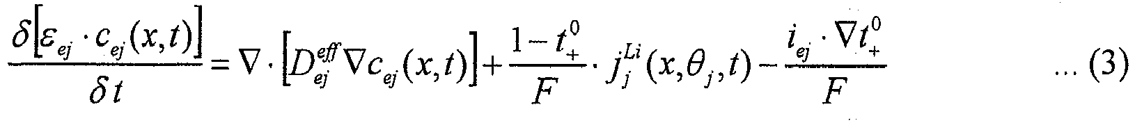


- Furthermore, an expression (9) is established as an expression relating to the principle of conservation of charge in the electrolytic solution and an expression (10) is established as an expression relating to the principle of conservation of charge in the active material. Furthermore, an expression (11) is established as an expression of an electrochemical reaction caused at the active material's interface, indicating a relationship between a current density I(t) and a reaction current density jj Li.


- Simplifying the Battery Model Expression in the Present Embodiment
- The primitive equations of expressions (1) to (11) are those disclosed in
non-patent document 1. Exactly applying these battery model expressions to a state estimation device mounted in an actual device and estimating a secondary battery's state on line is, however, extremely difficult due to a restriction on an ECU's (battery ECU 50's) operating load and operating time. Accordingly in the present embodiment the battery model expression is simplified, as will be described hereinafter. - With reference to
Fig. 4 , it is assumed in the present embodiment thatnegative electrode 12 andpositive electrode 15 each have an electrochemical reaction uniformly. More specifically, it is assumed that eachelectrode negative electrode 12 andpositive electrode 15 each internally have each active material's reaction uniformly, a single active material model will be handled in each ofnegative electrode 12 andpositive electrode 15. Consequently, theFig. 2 secondary battery's schematic structure is modeled as shown inFig. 4 . - In discharging, an electrode reaction is caused at a surface of the negative electrode's
active material model 18n.Active material model 18n thus has a lithium atom Li discharging an electron e- and thus becoming a lithium ion Li+ and thus discharged to an electrolytic solution inseparator 14. In contrast, an electrode reaction caused at a surface of the positive electrode'sactive material model 18p allows the lithium ion Li+ in the electrolytic solution to be taken in and the electron e- to be absorbed. The lithium atom Li is thus taken into the positive electrode'sactive material model 18p. As the negative electrode'sactive material model 18n discharges the lithium ion Li+ and the positive electrode'sactive material model 18p takes the lithium ion Li+ thereinto, a current flows from the positive electrode'scurrent collector 16 toward the negative electrode'scurrent collector 13. - In charging the secondary battery, in contrast, an electrode reaction caused at a surface of the negative electrode's
active material model 18n allows a lithium ion Li+ in the electrolytic solution to be taken in and an electrode reaction caused at a surface of the positive electrode'sactive material model 18p allows a lithium ion Li+ to be discharged to the electrolytic solution. The battery model expression models: the electrode reaction at the surface of each ofactive material model 18p (j = 1) andactive material model 18n (j = 2); how lithium diffuses inactive material model - As shown in
Fig. 5 , eachactive material model - As a result of these assumptions, primitive equations (1) to (6) and (8) in
non-patent document 1 are simplified to the following expressions (1') to (6') and (8'):


- In expression (3'), in particular, cej(t) is assumed to have a constant value, assuming that the electrolytic solution is invariable in concentration with time. Furthermore, for
active material models Fig. 5 . - Furthermore, expression (9), which relates to the principle of conservation of charge in the electrolytic solution, is simplified to an expression (12), indicated below, by expression (3') assuming that the electrodes have an electrochemical reaction therein uniformly and that the electrolytic solution is invariable in concentration with time. More specifically, the electrolytic solution has a potential φej approximated by a quadric of x, and an average potential φej# in the electrolytic solution used in calculating overvoltage ηj# is obtained by integrating expression (12) with respect to the electrode's thickness Lj, i.e., by an expression (13) indicated below.
- For
negative electrode 12, an expression (14) indicated below is established from expression (12), and accordingly, the electrolytic solution's average potential φe2# and the electrolytic solution's potential at a boundary withseparator 14 will have a difference in potential, as represented by an expression (15) indicated below. Similarly, forpositive electrode 15, the electrolytic solution's average potential φe1# and the electrolytic solution's potential at a boundary withseparator 14 will have a difference in potential, as represented by an expression (16) indicated below.


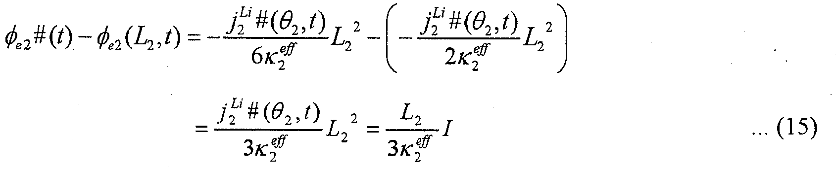

- Similarly, expression (10) relating to the principle of conservation of charge in the active material is also simplified to an expression (17) indicated below. More specifically, the active material also has a potential φsj approximated by a quadric of x, arid an average potential φsj# in the active material used in calculating overvoltage ηj# is obtained by integrating expression (17) with respect to the electrode's thickness Lj, i.e., by an expression (18) indicated below. Accordingly, similarly as described for the potential in the electrolytic solution, for
positive electrode 15, the active material's average potential φs1# and the active material's potential at a boundary with an electric collector (current collector 16) have a difference in potential, as indicated below by an expression (19). Fornegative electrode 12, an expression (20) is similarly established.


-
Fig. 6 represents a relationship between voltage V(t) of a terminal of the secondary battery and each average potential obtained as described above. Note that inFig. 6 ,separator 14 has a reaction current density jj Li = 0 and accordingly, a voltage drop inseparator 14 is proportional to current density I(t) and thus will be Ls/κs eff•I(t). - Furthermore, as it is assumed that each electrode internally has an electrochemical reaction uniformly, as described above, an expression (21) will be established between current density I(t) and reaction current density (or an amount of lithium generated) jj Li per a unit area of the electrode's plate, as follows:

- Thus from the
Fig. 6 relationship in potential and expression (21) an expression (22) indicated below is established for the battery's voltage V(t). Note that expression (22) is based on the relational expression in potential of expression (23) shown inFig. 6 . - Subsequently, an average overvoltage η#(t) is calculated. If jj Li is constant and in Butler-Volmer's relational expression, αaj = αcj = 0.5 (i.e., if charging and discharging are done equally in efficiency) then an expression (24) indicated below is established. By inversely transforming expression (24), average overvoltage η#(t) is obtained by an expression (25) indicated below.


- Then, in accordance with
Fig. 6 , average potentials φs1 and φs2 are obtained and substituted into expression (22) and furthermore, average overvoltages η1#(t) and η2#(t) obtained by expression (25) are substituted into expression (22). As a result, as based on simplified electrochemical reaction expressions (1'), (21) and relational expression in voltage (2'), a voltage-current relationship model expression (M1a) is derived in accordance with an electrochemical reaction model expression, as indicated below. - Furthermore, by a principle of conservation of lithium in concentration (a diffusion equation) or expression (4') and boundary condition expressions (5') and (6'), an active material diffusion model expression (M2a) is obtained for
active material models positive electrode 15 andnegative electrode 12, respectively.

- Note that in model expression (M1a) on the right-hand side the first term indicates an open circuit voltage (OCV) determined by a concentration of a reactant material (lithium) that is obtained at a surface of the active material and the second term indicates overvoltage (η1# - η2#) and the third term indicates a voltage drop attributed to the battery's current. More specifically, the secondary battery's pure direct current resistance is represented in expression (M1a) by Rd(T).
- Furthermore in expression (M2a) diffusion coefficients Ds1 and Ds2 used as a parameter value defining a diffusion rate of the reactant material, or lithium, are temperature-dependent. Accordingly, diffusion coefficients Ds1 and Ds2 are set, for example in accordance with a map shown in
Fig. 7 , as a variable parameter value set variably relative to the battery's temperature T detected bytemperature sensor 30. As shown inFig. 7 , diffusion coefficients Ds1 and Ds2 have a characteristic that relatively decreases when the battery has low temperature and that relatively increases as the battery's temperature increases. Accordingly such temperature dependence is reflected in previously preparing a map setting diffusion coefficients Ds1 and Ds2 in expression (M2a) as a parameter value of the battery in accordance with the battery's temperature T detected in accordance with a value Tb detected bytemperature sensor 30. - Note that if necessary, diffusion coefficients Ds1 and Ds2 may be dependent not only on temperature but also local SOC θ, and in that case, a two dimensional map is previously prepared that sets these diffusion coefficients as a parameter value in accordance with the battery's temperature T as detected and a local SOC θ as estimated.
- Similarly in expression (M1a) open circuit voltages U1 and U2 also have a dependence increasing or decreasing as local SOC θ decreases, as shown in
Fig. 8A and Fig. 8B . Accordingly, such local SOC dependence is reflected in previously setting a map setting open circuit voltages U1 and U2 in expression (M1a) in accordance with local SOC θ as estimated. Note thatFig. 8A represents dependence of open circuit voltage U1 on local SOC θ at the positive electrode (j = 1) andFig. 8B represents dependence of open circuit voltage U1 on local SOC θ at the negative electrode (j = 2). - Furthermore, although not shown in a figure, in expression (M1a), exchange current densities i01 and i02 also have dependence on local SOC θ and the battery's temperature T, and accordingly, a two dimensional map with θ and T serving as arguments is previously prepared and exchange current densities i01 and i02 are determined as a parameter value of the battery in accordance with local SOC θ currently obtained and the battery's temperature T currently obtained.
- Similarly, pure direct current resistance Rd is also temperature dependent, and accordingly, the temperature dependence is reflected in previously preparing a map setting pure direct current resistance Rd as a parameter value of the battery in accordance with the battery's temperature T detected in accordance with value Tb detected by
temperature sensor 30. - Note that the present specification describes for confirmation that the group of maps as described above can be prepared based on a result of an experiment such as a well known, alternate current impedance measurement or the like.
- Battery Model Expression in First Exemplary Variation: Sharing an Active Material Model
-
Fig. 4 shows a method that employs separate active material models fornegative electrode 12 andpositive electrode 15, respectively. Alternatively,negative electrode 12 andpositive electrode 15 may share an active material model to provide a modeling that contemplates a further alleviated operating load. In that case, thenegative electrode 12 andpositive electrode 15active material models 
- As a result, model expressions (M1a) and (M2a) that are further simplified to a model, i.e., expressions (M1b) and (M2b), are obtained, as indicated below. Furthermore, a battery model expression having applied thereto an active material model shared by the positive electrode and the negative electrode has current density I(t) and reaction current density jj Li in a relational expression of an expression (21') rather than (21).


- Battery Model Expression in Second Exemplary Variation: Linearly Approximating a Polarization Potential Term
- Expression (M1a) indicated above has an arcsinh term on the right-hand side at the second term indicating overvoltage. Accordingly, it is necessary to solve a non-linear expression. Accordingly, operating expression (M1a) requires a repetitive calculation, which may results in an increased operating load and in addition thereto impaired operation stability. Accordingly, expression (M1a) having the arcsinh term with a simple approximation (or a linear approximation) applied thereto, i.e., a voltage-current relationship model expression (M1c), is derived.


- Note that in expression (M1c) as a result of the linear approximation the right-hand side's second term will also be indicated by a product of current density I(t) and reaction resistance Rr. Reaction resistance Rr has dependence on local SOC θ and the battery's temperature T with respect to exchange current densities i01, i02, as indicated above by an expression (27). Accordingly, if voltage-current relationship model expression (M1c) is used, it will also be necessary to previously prepare a map that reflects dependence on local SOC θ and the battery's temperature T for reaction resistance Rr(θi, T) in accordance with a result of an experiment or the like and set the reaction resistance with reference to the map as a parameter of the battery, as appropriate.
- Consequently, voltage-current relationship model expression (M1c) will be represented as a linear model expression established between the battery's voltage V(t), the battery's current density I(t), Rr(θ, T) and Rd(T) serving as a parameter of the battery, and open circuit voltages U1, U2, as indicated above in an expression (28).
- Similarly, expression (M1b) indicated above also has an arcsinh term on the right-hand side at the second term linearly approximated to provide an expression (M1d) as indicated below. As well as expression (M1c), expression (M1d) is also expressed as a linear model expression.

- Configuration of Device Estimating a State of Secondary Battery According to First Embodiment
- Hereinafter will be described a configuration of a device estimating a state of a secondary battery according to the first embodiment of the present invention that is implemented by a combination of any of voltage-current relationship model expressions (M1a) to (M1d) and active material diffusion model (M2a) or (M2b) corresponding thereto. Note that it is assumed that the state estimation device described hereinafter is implemented basically by the
Fig. 1 battery ECU 50 processing a program. -
Fig. 9 is a block diagram schematically illustrating a configuration of a device estimating a state of a secondary battery according to the first embodiment of the present invention.Fig. 9 shows blocks, which are implemented basically bybattery ECU 50 processing a program. - With reference to
Fig. 9 , astate estimation device 50# includes adiffusion estimation unit 100, an open circuitvoltage estimation unit 110, acurrent estimation unit 120, a battery parametervalue setting unit 130, and a boundarycondition setting unit 140. -
Diffusion estimation unit 100 uses active material diffusion model expression (M2a) or (M2b), as based on a boundary condition set by boundarycondition setting unit 140 in accordance with expressions (5') and (6'), to sequentially perform an operation to obtain a distribution in concentration of lithium in the active material by differential formula, for example.Diffusion estimation unit 100 thus estimates a distribution in concentration of lithium, and based thereon, with the outermost region's lithium concentration serving as lithium concentration csej obtained at the interface of the material, local SOC θ is set in accordance with expression (7). - Open circuit
voltage estimation unit 110 obtains in accordance with a map reflecting a characteristic indicated inFig. 8A and Fig. 8B the positive and negative electrodes' respective open circuit voltages or an open circuit voltage of a composite of the positive electrode and the negative electrode. InFig. 9 , these will be indicated collectively as an open circuit voltage U(θ). - Battery parameter
value setting unit 130 sets a parameter for the battery in a battery model expression that is used in accordance with the battery's temperature T detected in accordance with value Tb detected bytemperature sensor 30 and the current local SOC θ based on the estimation done bydiffusion estimation unit 100. As has been described above, diffusion constants Ds1, Ds2, Ds in model expressions (M2a), (M2b) that are used indiffusion estimation unit 100 are set in accordance with the battery's temperature T, and other than that, pure direct current resistance Rt in model expressions (M1a) to (M1d), or exchange current densities i01, i02 in model expressions (M1a), (M1b) or reaction resistance Rr in model expressions (M1c), (M1d), and the like are set by battery parametervalue setting unit 130. - Based on expressions (M1a) to (M1d),
current estimation unit 120 follows any of expressions (M3a) to (M3d), as indicated below, substituting open circuit voltage U(θ) estimated by open circuitvoltage estimation unit 110 and the battery's current voltage V(t) detected in accordance with value Vb detected byvoltage sensor 34, to calculate the battery's current density I(t).
- For example, expression (M3a) corresponds to expression (M1a) solved for the battery's current density I(t). If expression (M3a), which is a nonlinear equation, is solved in Newton's method or the like, it can be solved by assuming an initial value of I(t) and furthermore, substituting the battery's voltage V(t), open circuit voltage U(θ) and a battery parameter value to calculate I(t), and iteratively performing a calculation until the calculated I(t) matches the assumed I(t).
- Similarly, for a battery model expression using expression (M1b), the battery's current density I(t) can be calculated by solving expression (M3b) by a method similar to that applied to expression (M3a).

- Furthermore, for a battery model expression of linearly approximated expressions (M1c) and (M1d), expressions (M3c) and (M3d) are used: the battery's voltage V(t), open circuit voltage U(θ) and a battery parameter value are substituted, and without performing an iterative calculation as done for a nonlinear equation, the battery's current density I(t) can uniquely be calculated. An alleviated operating load and increased operation stability can thus be achieved.


- Subsequently, boundary
condition setting unit 140 follows expression (21) or (21') to convert the current density I(t) obtained through an operation into a reaction current density (an amount of lithium generated) jj Li, and follows expression (6') to update a boundary condition for the active material diffusion model expressions (M2a), (M2b). - Thus in accordance with the first embodiment a device estimating a state of a secondary battery can receive the battery's voltage V(t) based on a value measured by
voltage sensor 34 and the battery's current temperature T based on a value measured bytemperature sensor 30 and accordingly provide an estimation based on diffusion model expressions (M2a), (M2b) for a reactant material (lithium) contained in an active material, and combine it with simplified voltage-current relationship model expressions (M1a) to (M1d) according to an electrochemical reaction model expression to estimate how the reactant material (lithium) is distributed in concentration in the active material, and based thereon, estimate the secondary battery's internal state with high precision. Thus a battery model expression can be implemented that is suitable for being mounted in an actual device, that adopts a simplified electrochemical reaction model expression to alleviate an operating load and allows a secondary battery's internal state to be estimated from an electrochemical reaction with high precision. - The device estimating a state of a secondary battery according to the first embodiment can use the secondary battery's estimated internal state to further estimate the state of charge (SOC) of
secondary battery 10. -
Fig. 10 illustrates how the device estimating a state of a secondary battery according to the first embodiment estimates SOC. - With reference to
Fig. 10 , the device estimating a state of a secondary battery according to the first embodiment further includes an averageconcentration calculation unit 160 and anSOC estimation unit 200. - Average
concentration calculation unit 160 uses an expression (29) indicated below to obtain an average lithium concentration csave(t) in the positive electrode'sactive material model 18p that is estimated bydiffusion estimation unit 100. Furthermore,SOC estimation unit 200 follows an expression (30), as indicated below, to generate an estimated SOC value SOCe for the entirety ofsecondary battery 10.

- As described above, lithium concentration cs1,k(t) in expression (29) is that of each region of
active material model 18p radially divided by N, as shown inFig. 5 , wherein k = 1 to N, and is estimated through diffusion model expressions (M2a), (M2b). Furthermore, ΔVk represents each region's volume and V represents the active material's entire volume. - Furthermore, if the positive and negative electrodes share an active material model, then average lithium concentration csave(t) can be obtained by obtaining an average value of a lithium concentration cs,k(t) of each region in the shared active material model, wherein k = 1 to N, similarly as done for expression (29).
-
Fig. 11 represents as one example a relationship of an average lithium concentration in an active material ofpositive electrode 15 and estimated SOC value SOCe. As shown inFig. 11 , as the average lithium concentration in the active material of the positive electrode increases, the SOC decreases. Accordingly, previously obtaining an average lithium concentration Cf that is obtained when the battery is fully charged (i.e., for SOC = 100%) and an average lithium concentration CO that is obtained when the battery is completely discharged (i.e., for SOC = 0%) and linearly interpolating them allows an SOC to be estimated in accordance with expression (30). -
Fig. 12 is a flowchart for illustrating how the device estimating a state of a secondary battery according to the first embodiment estimates the battery's state and SOC through a process having a series of steps. TheFig. 12 series of steps is invoked and executed bybattery ECU 50 for each predetermined operating period. - With reference to
Fig. 12 ,battery ECU 50 in step S100 obtains the battery's voltage V(t) based on value Vb detected byvoltage sensor 34 and in step S110 obtains the battery's current temperature T based on value Tb detected bytemperature sensor 30. - Furthermore,
battery ECU 50 in step S120 calculates local SOC θ based on a lithium concentration of a surface of the active material, as based on a distribution in concentration of lithium obtained in an operation previously performed through diffusion model expressions (M2a), (M2b). - Then,
battery ECU 50 in step S130 refers to a map following the characteristics shown inFig. 8A, Fig. 8B to calculate a value of open circuit voltage U(θ) from local SOC θ for each ofnegative electrode 12 andpositive electrode 15 or the positive and negative electrodes commonly. More specifically, step S130 corresponds to a function of open circuitvoltage estimation unit 110 shown inFig. 9 . - Furthermore,
battery ECU 50 in step S140 calculates an estimated value of the battery's current density I(t) by a function ofcurrent estimation unit 120 that is indicated inFig. 9 in accordance with any of voltage-current relationship model expressions (M1a) to (M1d) in accordance with a battery parameter value that is set in accordance with the battery's voltage V(t), open circuit voltage U(θ) and the battery's temperature T. - Furthermore,
battery ECU 50 in step S150 calculates reaction current density (or an amount of lithium generated) jj Li from the battery's estimated current density I(t), as based on expression (21) or (21'), and uses the calculated reaction current density to set a boundary condition for diffusion model equations (M2a), (M2b) for an interface of the active material (i.e., the active material's interface). More specifically, step S150 corresponds to a function of boundarycondition setting unit 140 shown inFig. 9 . - Then,
battery ECU 50 in step S160 follows diffusion equation models (M2a), (M2b) to calculate how lithium is distributed in concentration in an active material model set for each ofnegative electrode 12 andpositive electrode 15 or the positive and negative electrodes commonly, andbattery ECU 50 updates each region's estimated lithium concentration value. More specifically, step S160 corresponds to a function ofdiffusion estimation unit 100 shown inFig. 9 . Note that, as has been described above, at the time the concentration of lithium in the outermost divided region is obtained through an operation, and the obtained concentration is used in subsequently executing an operation when local SOC θ is calculated for a surface of the active material. - As a further step,
battery ECU 50 can perform step S170 to estimate a state of charge (SOC) for the entirety ofsecondary battery 10, based on the secondary battery's internal state obtained through steps S100 to S160. - For example, step S170 is configured of step S171 of calculating average lithium concentration csave based on the distribution in concentration of lithium in the active material, as obtained in step S160, and step S172 of calculating the secondary battery's state of charge based on average lithium concentration csave obtained in step S171.
Step S171 corresponds to a function of averageconcentration calculation unit 160 shown inFig. 10 and step S172 corresponds to a process performed bySOC estimation unit 200 shown inFig. 10 . - Thus the device estimating a secondary battery's charge according to the first embodiment receives the battery's voltage V(t) and accordingly estimates the battery's current (the battery's current density I(t)), and therefrom estimates the secondary battery's internal state. As such, as will be described hereinafter with reference to
Fig. 13 , it will have a function of self-modifying a model error. - With reference to
Fig. 13 , as can be understood with reference to battery model expression (M1a) and the like, whensecondary battery 10 is charged, a polarization potential ΔV is caused between the battery's voltage V(t) and open circuit voltage OCV, as shown inFig. 13 , and, as can also be understood from linearly approximated expressions (M1c), (M1d), this polarization potential will have a value in accordance with the battery's current density I. - Accordingly, if a battery model should have an operation error caused therein and open circuit voltage is underestimated relative to a true value, i.e., OCV (estimated) < OCV (true value) and SOC (estimated) < SOC (true value), and polarization ΔV (estimated) > ΔV (true value). Then, the battery's current density I(t) will be overestimated relative to a true value. As a result, reaction current density jj Li is also overestimated through expressions (21), (21'), and accordingly, in a subsequent operating period, an amount of SOC that is increased will be overestimated, and a model error relevant to SOC will be self-modified. Similarly, if open circuit voltage is overestimated relative to a true value, a model error relevant to SOC can be self-modified in a direction opposite to the above.
- In other words, the device estimating a secondary battery's charge according to the first embodiment allows a model estimation error that has once caused to be self-modified in a subsequent operation. A battery model error is not accumulated, and the secondary battery's internal state and state of charge (SOC) can be estimated with high precision.
- In a second embodiment will be described another method of estimating an SOC based on a result of estimating an internal state of a secondary battery according to the first embodiment.
-
Fig. 14 is a block diagram for illustrating how a device estimating a state of a secondary battery estimates an SOC according to the second embodiment. - With reference to
Fig. 14 , the device estimating a state of a secondary battery according to the second embodiment includes an offsetestimation unit 170, acurrent accumulation unit 180, and anSOC estimation unit 210. - Offset
estimation unit 170 calculates an offset error Iof ofcurrent sensor 32 in accordance with an expression (31), indicated below, as based on the battery's current density I(t) estimated bycurrent estimation unit 120 and the battery's current Ib(t) measured bycurrent sensor 32. In expression (31), a model battery current Im(t) is obtained by multiplying the battery's current density I(t) estimated bycurrent estimation unit 120 by the electrode's surface area. As indicated in expression (31), offsetestimation unit 170 accumulates a deviation of model battery current Im(t) and the battery's current Ib(t) measured bycurrent sensor 32 and divides the cumulative value by an accumulation time Tm to calculate a current offset error Iof.


-
Operation unit 175 subtracts offset error Iof estimated by offsetestimation unit 170 from the battery's current Ib(t) detected bycurrent sensor 32 to obtain the battery's corrected current Ibc(t). -
Current accumulation unit 180 obtains a cumulative value ∑Ibc of the battery's corrected current Ibc(t) calculated byoperation unit 175.SOC estimation unit 210 follows an expression (32) to obtain an amount of variation of SOC ΔSOCi in accordance with cumulative value ∑Ibc of the battery's corrected current Ibc(t). The amount of variation of SOC ΔSOCi will indicate an amount of variation of SOC that is introduced after an operation is previously performed to estimate an SOC before the present time. Furthermore,SOC estimation unit 210 follows an expression (33) to calculate the current estimated SOC value SOCe in accordance with a sum of an estimated SOC value SOCe(0) obtained in a previous operation for estimation and the amount of variation of SOC ΔSOCi obtained through expression (32). - Herein, as shown in
Fig. 15 , an error introduced in estimating a current by a battery model generally does not have something like an offset, and indicates a characteristic approaching zero as it is integrated for a long period of time. In contrast, as shown inFig. 16 ,current sensor 32's offset error is held at a constant value, and a deviation of the battery's current Ib(t), which is a value measured by a sensor, and a model estimated value Im(t) will constantly have a constant direct current component. Thus an operation performed in offsetestimation unit 170 based on expression (31) allows offset error Iof ofcurrent sensor 32 to be calculated. -
Fig. 17 is a flowchart for implementing estimating an SOC according to the second embodiment, as shown inFig. 14 , bybattery ECU 50. Such SOC estimation process as described above can be implemented by replacing theFig. 12 step S170 with theFig. 17 steps S173 to S175. - With reference to
Fig. 17 ,battery ECU 50 in step S173 calculates offset error Iof by accumulating a deviation of model estimated value Im(t) of the battery's current based on the battery's current density I(t) obtained through a battery model with the battery's voltage V(t) serving as an input and value Ib(t) sensed bycurrent sensor 32. In other words, step S173 corresponds to a function of offsetestimation unit 170 shown inFig. 14 . - Furthermore,
battery ECU 50 proceeds to step S174 to use offset error Iof to correct the sensor's value Ib(t) to calculate the battery's corrected current Ibc(t). Step S174 corresponds to a function ofoperation unit 175 shown inFig. 14 . - Then,
battery ECU 50 in step S175 calculates the secondary battery's estimated state-of-charge value SOCe based on the battery's corrected current Ibc(t) accumulated. In other words, step S175 corresponds to a function ofcurrent accumulation unit 180 andSOC estimation unit 210 shown inFig. 14 . - Thus in the second embodiment the device estimating a state of a secondary battery can estimate SOC such that an offset error is detected as based on a battery model expression and a current having the offset error removed therefrom is accumulated and therefrom state of charge (SOC) of the
secondary battery 10 can be estimated with high precision. -
Fig. 18 is a block diagram for illustrating how a device estimating a state of a secondary battery estimates an SOC according to the second embodiment in an exemplary variation. - With reference to
Fig. 18 , the device estimating a state of a secondary battery according to the second embodiment includesSOC estimation unit 200 described in the first embodiment, anSOC estimation unit 210# based on an accumulation of current, and anSOC estimation unit 220 considering a result of estimating an SOC byunit 200 and that of estimating an SOC byunit 210# together to generate a final estimated SOC value SOCe. -
SOC estimation unit 200, similarly as done in the first embodiment, estimates a model estimated SOC value SOCm, as based on an internal state of a secondary battery estimated in accordance with a battery model expression according to an embodiment of the present invention, in accordance with an average lithium concentration in an active material. The details are similar to those described with reference toFig. 10 . Accordingly, they will not be described repeatedly. - In contrast,
SOC estimation unit 210# obtains an amount of variation of SOC ΔSOCi, as based on the battery's current Ib(t) measured bycurrent sensor 32 and accumulated, for a period of an operation estimating an SOC. - Note that
SOC estimation unit 210# is not limited to a configuration obtaining the amount of variation of SOC ΔSOCi based on an estimation of an offset error ofcurrent sensor 32, as based on a battery model, and an accumulation of the battery's corrected current Ibc(t) with the offset error corrected, as has been described with reference toFig. 14 , and may be configured to obtain the amount of variation of SOC ΔSOCi by accumulating the battery's current Ib(t) measured bycurrent sensor 32. It should be noted, however, that configuring to use theFig. 14 SOC estimation unit 210 as theFig. 18 SOC estimation unit 210# allows the amount of variation of SOC ΔSOCi to be obtained with high precision through an effect of correcting the offset error. -
SOC estimation unit 220 calculates final estimated SOC value SOCe based on an expression (34):
- In expression (34), estimated SOC value SOCe is obtained by summing a previously estimated SOC value SOCe(0) plus a term of the amount of variation of SOC ΔSOCi, as based on a cumulative current, multiplied by a gain k1 plus a term of a difference of model estimated SOC value SOCm and previously estimated SOC value SOCe(0) multiplied by a gain k2.
- For gains k1 and k2, k1>k2, and, for example, gain k1 = 1.0 and gain k2 < 1.0 allow a cumulative current and estimating an internal state by a battery model to be combined together to estimate an SOC. For estimating how an SOC varies for a short period of time, the amount of variation of SOC ΔSOCi, which is highly reliable, can be reflected with a small time constant, and to resolve an SOC estimation error caused as the secondary battery is used over a long period of time, model estimated value SOCm that reflects the secondary battery's variation in internal state can be reflected with a relatively large time constant.
- Alternatively, gains k1 and k2 may be varied with the battery's state. For example, for low temperatures decreasing a battery model in precision, or when a large battery current is charged/discharged, it is preferable to decrease gain k2 and estimate an SOC mainly based on a cumulative current. In voltage-current relationship model expressions (M1c) and (M1d), in particular, with the arcsinh term linearly approximated, when the term I(t)/{2Ljasjioj(θ, T)} exceeds a predetermined absolute value, the battery model expression has an increased error. More specifically, when a large current flows (|I(t)| > > 0) and when the battery's temperature T is a low temperature decreasing exchange current density iej(θ, T), the above term has an increased absolute value and the battery model has an increased error. In such a case, for example, k2 = 0 can be set to stop estimating an SOC by the battery model and thus prevent the battery model from having an error increasing an error introduced in estimating a state of charge (SOC) of
secondary battery 10. -
Fig. 19 is a flowchart for implementing estimating an SOC according to the exemplary variation of the second embodiment, as shown inFig. 18 , bybattery ECU 50. - With reference to
Fig. 19 ,battery ECU 50 does not perform theFig. 12 step S170 and instead performs theFig. 19 steps S171, S172#, S173, S174, S175#, S176 to estimate an SOC according to the exemplary variation of the second embodiment as shown inFig. 18 . - With reference to
Fig. 19 ,battery ECU 50 after step S171 (similar to that shown inFig. 12 ) proceeds to step S172# to perform a step similar to step S172, i.e., calculate model estimated SOC value SOCm from average lithium concentration csave obtained at step S171. - Furthermore,
battery ECU 50 after steps S173, S174 (similar to those shown inFig. 17 ) proceeds to step S175# to calculate an amount of variation of SOC ΔSOCi, as based on corrected current value Ibc(t) accumulated, during a period of performing an operation to estimate an SOC. Note that step S175# of calculating the amount of variation of SOC ΔSOCi, as described above, may be done by accumulating value Ib(t) measured bycurrent sensor 32 without correcting offset error Iof. - Furthermore,
battery ECU 50 in step S176 calculates the current estimated SOC value SOCe in accordance with expression (34) based on previously estimated SOC value SOCe(0), model estimated SOC value SOCm obtained in step S172, and the amount of variation of SOC ΔSOCi obtained in step S175#. - Thus, estimating an SOC from an accumulation of current, which is highly reliable, for estimating how the secondary battery varies in SOC for a short period of time, and estimating an SOC by a battery model expression reflecting how the secondary battery's internal state varies can be combined, as appropriate, to estimate the secondary battery's state of charge (SOC) with high precision.
- The battery model expressions described in the first and second embodiments are derived on the assumption that a battery's entire current flows through an active material and contributes to an electrochemical reaction. In reality, however, for example for low temperatures in particular, an effect of an electric double layer capacitor that is caused at an interface of the electrolytic solution and the active material manifests and the battery's entire current is split into an electrochemical reaction current contributing to an electrochemical reaction and a current flowing through the capacitor.
-
Fig. 20 is a circuit diagram schematically showing a secondary battery's equivalent circuit model with such an electric double layer capacitor considered. - With reference to
Fig. 20 , the battery's current density I(t) corresponds to the battery's entire current component, which is split into an electrochemical reaction current component (a current density IEC(t)) flowing throughactive material model 18, which collectively represents the positive electrode'sactive material model 18p and the negative electrode'sactive material model 18n, and a capacitor's current component (a current density IC(t)) flowing through an electricdouble layer capacitor 19. In other words, the battery's current density I(t) is indicated by a sum of electrochemical reaction current density IEC(t) and the capacitor's current density IC(t). - The electrochemical reaction current component flowing through
active material model 18 contributes to an electrochemical reaction, whereas the capacitor's current component does not contribute to the electrochemical reaction, and pure direct current resistance Rd(t) indicated in expressions (M1a) to (M1d) has the battery's entire current component passing therethrough. - In the third embodiment, a battery model expression is configured to separate the capacitor's current component that passes through the electric double layer capacitor from the electrochemical reaction current component.
-
Fig. 21 is a block diagram for schematically illustrating a configuration of a device estimating a state of a secondary battery according to the third embodiment. - As can be understood from comparing
Fig. 21 withFig. 9 , the third embodiment provides a device estimating a state of a secondary battery withcurrent estimation unit 120 configured to further include acurrent operation unit 125. - Initially, when separating the capacitor's current component is considered in accordance with the
Fig. 20 battery model, voltage-current relationship model expression (M1a) is varied, as will be described hereinafter. - As can be understood from
Fig. 20 , fornegative electrode 12 andpositive electrode 15, a relationship is established between a total current density I(t), electrochemical reaction current density IEC(t), and the capacitor's current density IC(t), as indicated below by an expression (35).Active material model 18 has an electrochemical reaction involving only electrochemical reaction current density Ij EC(t). Accordingly, an electrochemical reaction expression simplified, assuming that in the electrode the electrochemical reaction is caused uniformly, i.e., expression (21), is modified to be an expression (36). - Furthermore, in expression (35), the capacitor's current density Ij C(t) is represented by an expression (37) indicated below.


- Note that expression (37) includes voltages ψ1(t) and ψ2(t), which are provided by a sum of open circuit voltage U(θ, t) and overvoltage η(t) of
positive electrode 15, and a sum of open circuit voltage U(θ, t) and overvoltage η(t) ofnegative electrode 12, as indicated below by expressions (38) and (39), respectively.

- I1 EC(t) and I2 EC(t) can thus be calculated by sequentially calculating voltages ψ1(t) and ψ2(t) in accordance with expressions (38) and (39), and solving expressions (37) and (35) having substituted therein a voltage value obtained in the previous operating period and that obtained in the current operating period. More specifically,
current operation unit 125 ofFig. 21 is configured by providing expressions (35) to (39) as simultaneous equations. - Furthermore, voltage-current relationship model expression (M1a) is converted to an expression (M4a), which corresponds to expression (M1a) such that a current density on the right-hand side at the second term indicating a polarization potential is replaced with electrochemical reaction current densities I1 EC(t) and I2 EC(t).

-
Current estimation unit 120 thus calculates the battery's current density I(t) based on model expression (M4a). More specifically, expression (M3a) having the battery's current density I(t) of a term that is relevant to overvoltage replaced with electrochemical reaction current densities I1 EC(t) and I2 EC(t) can be solved similarly as done for expression (M3a) to also obtain current density I(t). - Furthermore, as shown in expression (36), boundary
condition setting unit 140 uses electrochemical reaction current density Ij Ec(t) to set a boundary condition of the active material diffusion model expressions (M2a), (M2b) ofnegative electrode 12 andpositive electrode 15. - Similarly, a variation will be described that is provided when separating a capacitor's current component is considered for voltage-current relationship model expression (M1b).
- When a positive electrode and a negative electrode share an active material model, as indicated in expression (M1b), total current density I(t), electrochemical reaction current density IEC(t), and capacitor IC(t) indicated in the
Fig. 20 battery model have a relationship indicated below by an expression (40). Furthermore, expression (21') indicating a relationship between reaction current density jj Li and a current density is converted to an expression (41) indicated below. Furthermore, expressions (37) to (39) relevant to the capacitor's current are replaced with expressions (42) and (43) indicated below.


- Accordingly when separating the capacitor's current component is considered for voltage-current relationship model expression (M1b), expressions (40) to (43) configure
current operation unit 125 and an operation is performed to obtain reaction current density IEC(t). - Furthermore, model expression (M1b) in
current estimation unit 120 has the second term (or the overvoltage term) with current density I(t) substituted with electrochemical reaction current density IEC(t). In other words, it is converted to a model expression (M4b) indicated below. More specifically,current estimation unit 120 can also obtain current density I(t) by solving, in a manner similarly done for expression (M3a), expression (M3b) having a term relevant to overvoltage with the battery's current density I(t) replaced with electrochemical reaction current density IEC(t).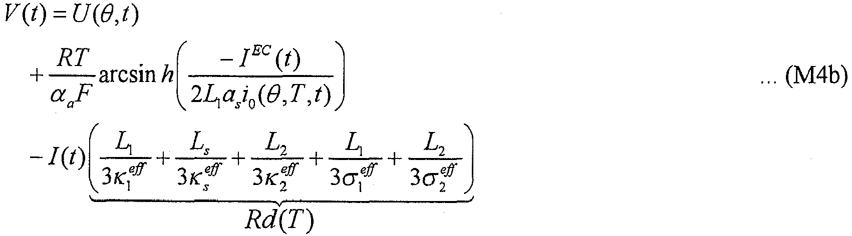
- Then will be described a variation that considers separating a capacitor's current component for a voltage-current relationship model expression having an arcsinh term linearly approximated, or voltage-current relationship model expression (M1c).
- Initially, for model expression (M1c) considering separate active material models for positive and negative electrodes, expressions (35), (37) are applied for a relationship between total current density I(t), electrochemical reaction current densities I1 EC(t), I2 EC(t), and the capacitor's current density IC(t), and expression (36) can be applied similarly for reaction current density. It should be noted, however, that for voltage ψ(t), expressions (38), (39) are not applied and an expression (44) instead is applied, as indicated below:

- In this case, expression (44) can also be provided together with expressions (35), (37) as simultaneous equations to obtain electrochemical reaction current densities I1 EC(t), I2 EC(t). More specifically,
current operation unit 125 ofFig. 21 is configured by providing expressions (35), (37), (44) as simultaneous equations. Furthermore, model expression (M1c) is converted to an expression (M4c) indicated below:
- Consequently in
current estimation unit 120 an expression (M3c') indicated below can be applied in place of expression (M3c) to obtain current density I(t).
- Finally will be described a variation considering a capacitor's current of voltage-current relationship model expression (M1d).
- In this case, which has a positive electrode and a negative electrode sharing a common active material model and also considers the capacitor's current, an expression (45) indicated below is established for current density I(t), electrochemical reaction current density IEC(t) and the capacitor's current density IC(t). Expression (45) includes ψ(t), which is indicated by an expression (46), as indicated below, as a sum of open circuit voltage and polarization potential, as has been described previously. Furthermore, reaction current density jj Li corresponding to an amount of lithium generated is obtained by an expression (47) using electrochemical reaction current density IEC(t), as indicated below.


- In this case also, voltage ψ(t) defined by expression (46) that is provided together with expression (45) as simultaneous equations can be solved to obtain electrochemical reaction current density IEC(t). In other words,
current operation unit 125 ofFig. 21 is configured by providing expressions (45), (46) as simultaneous equations. - Furthermore, voltage -current model expression (M1d) in
current estimation unit 120 has a right-hand side having a second term (a term relevant to polarization potential) with current density I(t) replaced with electrochemical reaction current density IEC(t) and is thus converted to a model expression (M4d). Consequently incurrent estimation unit 120 an expression (M3d') can be applied in place of expression (M3d) to obtain current density I(t).

- As has been described above, the third embodiment provides a device estimating a state of a secondary battery, that can separate current density I(t) into electrochemical reaction current density IEC(t) and a capacitor's current density IC(t) that does not contribute to an electrochemical reaction to estimate the battery's internal behavior.
- The device can thus estimate the secondary battery's internal state, more specifically, how lithium is distributed in concentration in an active material, more precisely to estimate the internal state more precisely. Furthermore, combining such a device estimating a secondary battery's internal state, as described above, with estimating an SOC, as has been described in the latter half of the first embodiment or the second embodiment, allows the secondary battery's state of charge (SOC) to be estimated with high precision.
- Furthermore, electric
double layer capacitor 19 shown inFig. 20 is temperature-dependent. Accordingly, a map that is also previously prepared, as based on a result of an experiment or the like, for a capacitance C (C1, C2) in a model expression used incurrent operation unit 125 allows battery parametervalue setting unit 130 to set the capacitance variably in accordance with the battery's temperature T. - The first to third embodiments as described above have been described with a secondary battery implemented as a lithium ion battery. However, the present device estimating a state of a secondary battery is applicable not only to the lithium ion battery but also other types of secondary batteries without particularly limiting the type of load. For a nickel hydrogen battery, for example, calculating by a diffusion equation how protons are distributed in density in an active material as a reaction-involved material and defining an open circuit voltage as a function of the protons of a surface of the active material allow the method of the present invention to be similarly applied.
- Furthermore, it is also described for confirmation that estimating how a reactant material is distributed in concentration by the device estimating an internal state of a secondary battery, as described in the present invention with reference to
Fig. 1 to Fig. 9 , can also be combined with a method of estimating an SOC that is other than described in the present specification to implement a device estimating a state of charge (SOC) of a secondary battery. - It should be understood that the embodiments disclosed herein are illustrative and non-restrictive in any respect. The scope of the present invention is defined by the terms of the claims, rather than the description above.
- The present device estimating a state of a secondary battery is applicable to a secondary battery used in a power supply system configured to allow a chargeable secondary battery to supply a load with power and to also allow the secondary battery to be charged, as required, while the load is in operation.
Claims (14)
- A device for estimating a state of a secondary battery including first and second electrodes (12, 15) configured to include an active material (18) containing a reactant material contributing to an electrochemical reaction and an ion conductor (14) for conducting between said first and second electrodes said reactant material ionized, the device comprising:a voltage detector (34) for detecting a voltage (Vb) of said battery between said first and second electrodes;a diffusion estimation unit (100) for estimating a distribution in concentration of said reactant material in accordance with an active material diffusion model expression (M2a, M2b) defining said distribution in concentration of said reactant material in said active material, as based on a given boundary condition;an open circuit voltage estimation unit (110) for estimating an open circuit voltage (U(θ)) between said first and second electrodes, as based on a concentration of said reactant material obtained at an interface of said active material with an electrolytic solution, as estimated by said diffusion estimation unit;a current estimation unit (120) for estimating a density (I(t)) of a current of said secondary battery in accordance with a voltage-current relationship model expression (M3a-M3d) based on the electrochemical reaction and indicating a relationship between said open circuit voltage, an overvoltage (η1# - η2#) calculated in accordance with said density of said current of said secondary battery, a voltage drop (I(t)●Rd(T)) caused in accordance with said density of said current of said secondary battery, and said voltage of said battery, whereinsaid voltage-current relationship model expression is such that the current estimation unit (120) is configured to uniquely calculate said density of said current of said secondary battery without performing an iterative calculation, by substituting in said voltage-current relationship model expression said voltage of said battery detected by said voltage detector, said open circuit voltage estimated by said open circuit voltage estimation unit, and a parameter value of said secondary battery; anda boundary condition setting unit (140) for calculating a reaction current density (jj Li) at said interface, as based on said density of said current of said battery estimated by said current estimation unit, and sets said boundary condition for said active material diffusion model expression for said interface in accordance with said reaction current density calculated.
- The device estimating a state of a secondary battery according to claim 1, further comprising:a temperature detector (30) that detects a temperature (Tb) of said secondary battery; anda parameter value setting unit (130) for setting said parameter value-variably in accordance with at least said temperature of said battery, said parameter value setting unit further setting a parameter value (Ds1(T), Ds2(T)) indicative of a diffusion rate in said active material diffusion model expression variably in accordance with at least said temperature of said battery.
- The device estimating a state of a secondary battery according to claim 2, wherein:said voltage-current relationship model expression is configured by a linearly approximated expression indicating that said open circuit voltage (U(θ)) minus a product of said density (I(t)) of said current of said battery and an electrical resistance provided per a unit area of said electrode that is served as said parameter value is a voltage equal to said voltage of said battery; andsaid parameter value setting unit sets said electrical resistance (Rr(θ), Rd(T)) variably in accordance with said concentration of said reactant material obtained at said interface, as estimated by said diffusion estimation unit, and said temperature of said battery detected by said temperature detector.
- The device estimating a state of a secondary battery according to claim 1, further comprising a current operation unit (125) that separates said density (I(t)) of said current of said secondary battery in total into a first current density (IEC(t)) contributing to said electrochemical reaction and a second current density (IC(t)) caused by a component caused in said secondary battery for an electric double layer capacitor, wherein:said boundary condition setting unit (140) calculates said reaction current density (jj Li) at said interface, as based on said first current density calculated by said current operation unit; andin said voltage-current relationship model expression, said overvoltage (η1#-η2#) is calculated based on said first current density.
- The device estimating a state of a secondary battery according to claim 4, further comprising:a temperature detector (30) that detects a temperature of said secondary battery; anda parameter value setting unit (130) for setting said parameter value variably in accordance with at least said temperature of said battery, wherein:said voltage-current relationship model expression is configured of a linearly approximated expression indicating that a product of said first current density and a first electrical resistance provided per a unit area of said electrode that is served as said parameter value is equal to said voltage of said battery; and an expression indicating that said second current density flowing through said capacitor per said unit area of said electrode that is served as said parameter value is a value proportional to an amount of said voltage of said battery that varies with time; andsaid parameter value setting unit sets said first electrical resistance (Rr) variably in accordance with said concentration of said reactant material obtained at said interface, as estimated by said diffusion estimation unit, and said temperature of said battery detected by said temperature detector, and also variably sets a capacitance (C) per said unit area of said electrode in accordance with said temperature of said battery.
- The device estimating a state of a secondary battery according to claim 1, wherein said diffusion estimation unit (100) has said active material diffusion model expression represented by a polar coordinate for each of said first and second electrodes.
- The device estimating a state of a secondary battery according to claim 1, wherein said diffusion estimation unit (100) has said active material diffusion model expression represented by a polar coordinate and shared by said first and second electrodes.
- The device estimating a state of a secondary battery according to claim 1, wherein said voltage-current relationship model expression is derived as based on a voltage equation indicating a relationship between average potentials of said active material and said electrolytic solution, an average value of an overvoltage generated as said electrochemical reaction is caused at said interface, and said open circuit voltage; and an electrochemical reaction expression indicating a relationship between said density of said current of said battery and said average value of said overvoltage.
- The device estimating a state of a secondary battery according to claim 8, wherein, assuming that said first and second electrodes each have said electrochemical reaction caused therein uniformly without site dependence, said voltage-current relationship model expression is derived by simplifying a distribution in potential of said active material in said electrode and said electrolytic solution to a quadric, and in that condition, obtaining said average potentials of said active material and said electrolytic solution.
- The device estimating a state of a secondary battery according to any one of claims 1-9, further comprising:an average concentration calculation unit (160) that calculates an average concentration of said reactant material in said active material, as based on said distribution in concentration of said reactant material estimated by said diffusion estimation unit (100); anda first state-of-charge estimation unit (200) that estimates a state of charge of said secondary battery in accordance with a previously obtained correspondence relationship between said average concentration and said state of charge, as based on said average concentration calculated by said average concentration calculation unit.
- The device estimating a state of a secondary battery according to claim 10, further comprising:a current detector (32) that detects a current (Ibc(t)) of said secondary battery;a second state-of-charge estimation unit (210, 210#) that estimates an amount (ΔSOCi) of variation of said state of charge of said secondary battery, as based on said current of said battery accumulated; anda third state-of-charge estimation unit (220) that sequentially updates an estimated value (SOCe) of said state of charge of said secondary battery, as based on a result of estimating by said first and second state-of-charge estimation units, wherein:said third state-of-charge estimation unit calculates a current value of said estimated value of said state of charge by reflecting said amount of variation of said state of charge from said previous value estimated by said second state-of-charge estimation unit, and an error in state of charge between a current state of charge estimated by said first state-of-charge estimation unit and a previous value (SOCe(0)) of said estimated value of said state of charge, on said previous value; andsaid amount of variation of said state of charge is reflected with a time constant relatively smaller than that applied in reflecting said error in state of charge.
- The device estimating a state of a secondary battery according to claim 10, further comprising:a current detector (32) that detects a current (Ibc(t)) of said secondary battery;a second state-of-charge estimation unit (210, 210#) that estimates an amount (ΔSOCi) of variation of said state of charge of said secondary battery, as based on said current of said battery accumulated; anda third state-of-charge estimation unit (220) that sequentially updates an estimated value (SOCe) of said state of charge of said secondary battery, as based on a result of estimating by said first and second state-of-charge estimation units, wherein:said third state-of-charge estimation unit calculates a current value of said estimated value of said state of charge by reflecting said amount of variation of said state of charge from said previous value estimated by said second state-of-charge estimation unit, and an error in state of charge between a current state of charge estimated by said first state-of-charge estimation unit and a previous value (SOCe(0)) of said estimated value of said state of charge, on said previous value; andwhen said current of said battery has an absolute value larger than a predetermined value or said temperature of said secondary battery is lower than a predetermined temperature, said third state-of-charge estimation unit calculates said current value of said estimated value of said state of charge with ceasing to reflect said error in state of charge.
- The device estimating a state of a secondary battery according to claim 11 or 12, further comprising an offset estimation unit (170) that calculates an estimated value of said current of said battery, as based on said density of said current of said battery estimated by said current estimation unit (120), and estimates an offset error (Iof) of said current detector, as based on an error of said estimated value of said current of said battery and a value (Ibc(t)) detected by said current detector (32), wherein said second state-of-charge estimation unit (210) uses said offset error estimated by said offset estimation unit to correct said value of said current of said battery detected by said current detector, and estimates said amount of variation of said state of charge of said secondary battery, as based on an accumulation of said value detected that is corrected.
- The device estimating a state of a secondary battery according to any one of claims 1 -9, further comprising:a current detector (32) that detects a current (Ibc(t)) of said secondary battery;an offset estimation unit (170) that calculates an estimated value of said current of said battery, as based on said density of said current of said battery estimated by said current estimation unit, and estimates an offset error of said current detector, as based on an error of said estimated value of said current of said battery and a value detected by said current detector; anda state-of-charge estimation unit (210) that uses said offset error estimated by said offset estimation unit to correct said value of said current of said battery detected by said current detector, and estimates an amount of variation of said state of charge of said secondary battery, as based on an accumulation of said value detected that is corrected.
Applications Claiming Priority (2)
| Application Number | Priority Date | Filing Date | Title |
|---|---|---|---|
| JP2007077598A JP4872743B2 (en) | 2007-03-23 | 2007-03-23 | Secondary battery state estimation device |
| PCT/JP2008/054693 WO2008126631A1 (en) | 2007-03-23 | 2008-03-07 | State estimating device for secondary battery |
Publications (3)
| Publication Number | Publication Date |
|---|---|
| EP2107385A1 EP2107385A1 (en) | 2009-10-07 |
| EP2107385A4 EP2107385A4 (en) | 2014-01-01 |
| EP2107385B1 true EP2107385B1 (en) | 2018-06-20 |
Family
ID=39863758
Family Applications (1)
| Application Number | Title | Priority Date | Filing Date |
|---|---|---|---|
| EP08722090.1A Expired - Fee Related EP2107385B1 (en) | 2007-03-23 | 2008-03-07 | State estimating device for secondary battery |
Country Status (5)
| Country | Link |
|---|---|
| US (1) | US8093902B2 (en) |
| EP (1) | EP2107385B1 (en) |
| JP (1) | JP4872743B2 (en) |
| CN (1) | CN101641607B (en) |
| WO (1) | WO2008126631A1 (en) |
Cited By (2)
| Publication number | Priority date | Publication date | Assignee | Title |
|---|---|---|---|---|
| KR20180115817A (en) * | 2013-02-21 | 2018-10-24 | 로베르트 보쉬 게엠베하 | Method and system for estimating a capacity of individual electrodes and the total capacity of a lithium-ion battery system |
| EP4016098A1 (en) | 2020-12-18 | 2022-06-22 | INTILION GmbH | Method and device for robust online determination of the state of large battery storage systems |
Families Citing this family (84)
| Publication number | Priority date | Publication date | Assignee | Title |
|---|---|---|---|---|
| US9331513B2 (en) * | 2008-04-11 | 2016-05-03 | Apple Inc. | Adaptive surface concentration battery charging |
| US8754611B2 (en) | 2008-04-11 | 2014-06-17 | Apple Inc. | Diffusion-limited adaptive battery charging |
| US8624560B2 (en) * | 2008-04-11 | 2014-01-07 | Apple Inc. | Controlling battery charging based on current, voltage and temperature |
| WO2011001471A1 (en) * | 2009-07-02 | 2011-01-06 | トヨタ自動車株式会社 | Device and method to sense battery internal state |
| JP6053522B2 (en) * | 2009-11-19 | 2016-12-27 | ローベルト ボツシユ ゲゼルシヤフト ミツト ベシユレンクテル ハフツングRobert Bosch Gmbh | Method and apparatus for performing error compensation current measurement of a storage battery |
| US20130069660A1 (en) * | 2010-02-17 | 2013-03-21 | Julien Bernard | Method for in situ battery diagnostic by electrochemical impedance spectroscopy |
| JP5537236B2 (en) | 2010-04-13 | 2014-07-02 | トヨタ自動車株式会社 | Lithium ion secondary battery deterioration determination device and deterioration determination method |
| JP5821256B2 (en) * | 2010-06-09 | 2015-11-24 | 日産自動車株式会社 | Battery charging system |
| JP5842421B2 (en) * | 2010-07-20 | 2016-01-13 | 日産自動車株式会社 | Battery state estimation device |
| JP5329500B2 (en) * | 2010-09-06 | 2013-10-30 | カルソニックカンセイ株式会社 | Battery charge rate estimation device |
| US8612168B2 (en) * | 2010-09-22 | 2013-12-17 | GM Global Technology Operations LLC | Method and apparatus for estimating battery capacity of a battery |
| US8527225B2 (en) | 2010-10-05 | 2013-09-03 | Toyota Jidosha Kabushiki Kaisha | Estimation apparatus and estimation method |
| CN102792175B (en) | 2010-10-05 | 2015-03-25 | 丰田自动车株式会社 | Method for estimating state of energy storage element and state estimation device |
| KR20130121143A (en) * | 2011-03-07 | 2013-11-05 | 가부시끼가이샤 히다치 세이사꾸쇼 | Battery state estimating method and battery management system |
| JP5607569B2 (en) * | 2011-03-31 | 2014-10-15 | トヨタ自動車株式会社 | VEHICLE CHARGING DEVICE, VEHICLE HAVING THE SAME, AND CURRENT SENSOR OFFSET CORRECTION |
| US10234512B2 (en) | 2011-06-11 | 2019-03-19 | Sendyne Corporation | Current-based cell modeling |
| EP2746796B1 (en) * | 2011-08-03 | 2016-07-20 | Toyota Jidosha Kabushiki Kaisha | Device for estimating state of deterioration of secondary battery and method for estimating state of deterioration |
| US8612078B2 (en) * | 2011-08-08 | 2013-12-17 | Bae Systems Controls Inc. | Parallel hybrid electric vehicle power management system and adaptive power management method and program therefor |
| JP5737106B2 (en) * | 2011-09-26 | 2015-06-17 | トヨタ自動車株式会社 | Secondary battery state estimation device |
| JP5989320B2 (en) * | 2011-10-07 | 2016-09-07 | トヨタ自動車株式会社 | Vehicle control apparatus and remaining capacity estimation method |
| JP2013083612A (en) * | 2011-10-12 | 2013-05-09 | Mitsumi Electric Co Ltd | Battery state measurement method and battery state measurement apparatus |
| FR2983305B1 (en) * | 2011-11-29 | 2014-01-24 | Peugeot Citroen Automobiles Sa | METHOD FOR DETERMINING THE VOLTAGE OF AN ELECTRIC BATTERY |
| EP2804249B1 (en) | 2012-01-13 | 2017-08-30 | Toyota Jidosha Kabushiki Kaisha | Method for controlling and device for controlling secondary battery |
| US20140340045A1 (en) * | 2012-01-26 | 2014-11-20 | Calsonic Kansei Corporation | Apparatus for battery state estimation |
| DE112012005801B4 (en) | 2012-02-01 | 2022-06-15 | Toyota Jidosha Kabushiki Kaisha | Electrical storage system |
| JP6065561B2 (en) * | 2012-03-08 | 2017-01-25 | 日産自動車株式会社 | Secondary battery control device and SOC detection method |
| JP5783122B2 (en) * | 2012-04-11 | 2015-09-24 | トヨタ自動車株式会社 | Battery state estimation device |
| EP2851699B1 (en) | 2012-05-15 | 2017-04-12 | Toyota Jidosha Kabushiki Kaisha | Battery system and polarization determination method for secondary battery |
| EP3901642B1 (en) | 2012-06-13 | 2022-09-14 | LG Energy Solution, Ltd. | Apparatus and method for estimating soc of secondary battery including blended cathode material |
| WO2013187583A1 (en) | 2012-06-13 | 2013-12-19 | 주식회사 엘지화학 | Apparatus and method for estimating voltage of secondary cell including mixed cathode material |
| US9046583B2 (en) | 2012-06-13 | 2015-06-02 | Lg Chem, Ltd. | Apparatus and method for estimating voltage of secondary battery including blended material in electrode |
| WO2014008278A1 (en) * | 2012-07-02 | 2014-01-09 | Robert Bosch Gmbh | System and method for fast charging of lithium-ion batteries with improved safety |
| JP5856548B2 (en) * | 2012-08-02 | 2016-02-09 | トヨタ自動車株式会社 | Secondary battery state estimation device |
| JP5864380B2 (en) * | 2012-08-02 | 2016-02-17 | トヨタ自動車株式会社 | Secondary battery state estimation device |
| US9081068B2 (en) | 2012-09-18 | 2015-07-14 | Apple Inc. | Method and apparatus for determining a capacity of a battery |
| KR101547006B1 (en) * | 2012-10-26 | 2015-08-24 | 주식회사 엘지화학 | Apparatus and method for estimating state of charging of battery |
| US10209319B2 (en) | 2013-02-01 | 2019-02-19 | Toyota Jidosha Kabushiki Kaisha | State of deterioration or state of charges estimating apparatus for secondary battery |
| JP6029745B2 (en) * | 2013-03-28 | 2016-11-24 | 三洋電機株式会社 | Secondary battery charge state estimation device and secondary battery charge state estimation method |
| JP6155774B2 (en) | 2013-04-03 | 2017-07-05 | 株式会社Gsユアサ | State estimation device and state estimation method |
| DE112013006931T5 (en) * | 2013-04-11 | 2016-01-07 | Toyota Jidosha Kabushiki Kaisha | battery system |
| FR3006450B1 (en) * | 2013-06-04 | 2015-05-22 | Renault Sa | METHOD FOR ESTIMATING THE HEALTH STATUS OF AN ELECTROCHEMICAL CELL FOR STORING ELECTRIC ENERGY |
| DE102013106083B4 (en) * | 2013-06-12 | 2022-02-10 | Infineon Technologies Ag | Method and device for determining a parameter of a model of a technical device |
| FR3009389B1 (en) * | 2013-08-02 | 2017-02-10 | Commissariat Energie Atomique | ENERGY MANAGEMENT IN A BATTERY |
| CN104714178B (en) * | 2013-12-13 | 2017-10-10 | 北汽福田汽车股份有限公司 | The method of testing of battery charging and discharging boundary condition |
| US10345385B2 (en) * | 2014-05-12 | 2019-07-09 | Gm Global Technology Operations Llc. | Battery state estimation systems and methods using a nonlinear resistance element |
| US9843069B2 (en) * | 2014-09-26 | 2017-12-12 | Ford Global Technologies, Llc | Battery capacity degradation resolution methods and systems |
| DE102015117171B4 (en) * | 2014-10-09 | 2019-03-21 | Denso Corporation | BATTERIEZUSTANDSABSCHÄTZVORRICHTUNG |
| JP6409721B2 (en) * | 2014-10-09 | 2018-10-24 | 株式会社デンソー | Battery state estimation device |
| JP6490414B2 (en) | 2014-12-05 | 2019-03-27 | 古河電気工業株式会社 | Secondary battery state detection device and secondary battery state detection method |
| JP6355552B2 (en) * | 2014-12-25 | 2018-07-11 | マクセルホールディングス株式会社 | Lithium ion secondary battery charging method and charging control system thereof |
| US10193198B2 (en) * | 2015-03-13 | 2019-01-29 | Panasonic Intellectual Property Management Co., Ltd. | Cell management device and power supply device |
| JP6350366B2 (en) * | 2015-04-07 | 2018-07-04 | 株式会社デンソー | Charge / discharge control device |
| JP6383704B2 (en) * | 2015-07-02 | 2018-08-29 | 日立オートモティブシステムズ株式会社 | Battery control device |
| KR102527326B1 (en) * | 2015-08-20 | 2023-04-27 | 삼성전자주식회사 | A method and a battery system for predicting State of Charge (SoC) of a battery |
| US10137797B2 (en) * | 2015-09-28 | 2018-11-27 | Ford Global Technologies, Llc | Battery state of charge estimation based on current pulse duration |
| US10224579B2 (en) | 2015-12-31 | 2019-03-05 | Robert Bosch Gmbh | Evaluating capacity fade in dual insertion batteries using potential and temperature measurements |
| JP6220904B2 (en) * | 2016-01-14 | 2017-10-25 | 本田技研工業株式会社 | Power storage device |
| US10263447B2 (en) | 2016-01-29 | 2019-04-16 | Robert Bosch Gmbh | Secondary battery management system |
| US10686321B2 (en) * | 2016-01-29 | 2020-06-16 | Robert Bosch Gmbh | Secondary battery management |
| JP6701936B2 (en) * | 2016-05-10 | 2020-05-27 | 日立化成株式会社 | Battery state detecting device, vehicle, program, and battery state detecting method |
| JP6668945B2 (en) * | 2016-05-25 | 2020-03-18 | トヨタ自動車株式会社 | Battery recharge rate estimation device |
| CN109716152B (en) | 2016-06-28 | 2021-07-06 | 宝马股份公司 | Method and apparatus for estimating voltage of battery |
| JP6883742B2 (en) * | 2016-09-16 | 2021-06-09 | パナソニックIpマネジメント株式会社 | Battery diagnostic methods, battery diagnostic programs, battery management devices, and power storage systems |
| JP6772791B2 (en) * | 2016-11-30 | 2020-10-21 | トヨタ自動車株式会社 | Battery system |
| US10566811B2 (en) * | 2017-01-11 | 2020-02-18 | Samsung Electronics Co., Ltd. | Method and apparatus estimating and controlling battery state |
| KR102468896B1 (en) * | 2017-01-11 | 2022-11-21 | 삼성전자주식회사 | Method and apparatus for estimating battery state |
| US10923774B2 (en) | 2017-03-07 | 2021-02-16 | Denso Corporation | Battery state estimating device and power supply device |
| JP6790931B2 (en) | 2017-03-14 | 2020-11-25 | 株式会社デンソー | Battery state estimator |
| JP6822300B2 (en) | 2017-04-27 | 2021-01-27 | トヨタ自動車株式会社 | Charge rate estimation method and in-vehicle battery system |
| DE102017112355B4 (en) * | 2017-06-06 | 2020-07-09 | Einhell Germany Ag | Battery management system for a lithium-ion battery of an electrical device and method for operating a lithium-ion battery of an electrical device |
| JP6947014B2 (en) * | 2017-12-25 | 2021-10-13 | トヨタ自動車株式会社 | Rechargeable battery system and rechargeable battery control method |
| JP7352333B2 (en) * | 2018-06-06 | 2023-09-28 | 株式会社Subaru | Power system control device |
| JP2020013634A (en) * | 2018-07-13 | 2020-01-23 | 株式会社デンソー | State estimation device of secondary battery |
| CN113016099B (en) * | 2018-10-26 | 2024-02-06 | 日本汽车能源株式会社 | Battery control device |
| KR102405514B1 (en) * | 2018-12-06 | 2022-06-03 | 주식회사 엘지에너지솔루션 | Charging Method of Secondary Battery and Method thereof |
| CN110865250A (en) * | 2019-10-15 | 2020-03-06 | 国网江苏省电力有限公司电力科学研究院 | Power distribution equipment state monitoring device integrating current monitoring and heating detection method |
| US20230305066A1 (en) * | 2020-08-04 | 2023-09-28 | Lg Energy Solution, Ltd. | System and method for optimization of current excitation for identification of battery electrochemical parameters based on analytic sensitivity expression |
| KR20220029109A (en) * | 2020-09-01 | 2022-03-08 | 삼성전자주식회사 | Method and apparatus estimating a state of battery |
| KR20220039249A (en) * | 2020-09-22 | 2022-03-29 | 주식회사 엘지에너지솔루션 | Battery apparatus and method for estimating battery state |
| CN112903539B (en) * | 2021-03-29 | 2022-12-27 | 清华大学深圳国际研究生院 | Imaging detection device and method for diffusion coefficient of electrolyte of flow battery |
| JP2023148466A (en) * | 2022-03-30 | 2023-10-13 | 株式会社デンソー | Impedance measuring device for secondary battery |
| CN114912327B (en) * | 2022-05-27 | 2023-03-24 | 上海玫克生储能科技有限公司 | Method and device for calculating current density in battery electrochemical model and storage medium |
| CN115084693B (en) * | 2022-06-28 | 2023-04-21 | 上海玫克生储能科技有限公司 | Lithium battery solid-phase concentration correction method, system and storage medium |
| CN115436812B (en) * | 2022-09-23 | 2023-08-04 | 上海玫克生储能科技有限公司 | Electrochemical model parameter identification method and system based on splicing factors |
Family Cites Families (13)
| Publication number | Priority date | Publication date | Assignee | Title |
|---|---|---|---|---|
| US4623597A (en) * | 1982-04-28 | 1986-11-18 | Energy Conversion Devices, Inc. | Rechargeable battery and electrode used therein |
| US6045941A (en) * | 1997-07-08 | 2000-04-04 | Schlumberger Technology Corporation | Method to determine the state of charge and remaining life of lithium batteries used in oilfield services applications |
| JPH11204149A (en) * | 1998-01-13 | 1999-07-30 | Denso Corp | Lithium battery remaining capacity measuring method |
| JP3669673B2 (en) * | 1999-06-18 | 2005-07-13 | 松下電器産業株式会社 | Electrochemical element degradation detection method, remaining capacity detection method, and charger and discharge control device using the same |
| US20030184307A1 (en) * | 2002-02-19 | 2003-10-02 | Kozlowski James D. | Model-based predictive diagnostic tool for primary and secondary batteries |
| JP4061965B2 (en) * | 2002-05-14 | 2008-03-19 | ソニー株式会社 | Battery capacity calculation method |
| JP4032934B2 (en) * | 2002-11-15 | 2008-01-16 | ソニー株式会社 | Battery capacity calculation method, battery capacity calculation device, and battery capacity calculation program |
| JP3714321B2 (en) | 2002-11-25 | 2005-11-09 | 日産自動車株式会社 | Secondary battery charge rate estimation device |
| WO2004068157A1 (en) * | 2003-01-30 | 2004-08-12 | Robert Bosch Gmbh | State variable and parameter estimator comprising several partial models for an electrical energy storage device |
| JP2005037230A (en) | 2003-07-14 | 2005-02-10 | Toyota Motor Corp | Battery degradation detection device and method |
| WO2007004098A1 (en) * | 2005-06-30 | 2007-01-11 | Koninklijke Philips Electronics N.V. | Method and charger for boost charging a chargeable battery on the basis of a physical model |
| JP4802945B2 (en) * | 2006-08-31 | 2011-10-26 | トヨタ自動車株式会社 | Secondary battery control system and hybrid vehicle equipped with the same |
| JP2008058278A (en) * | 2006-09-04 | 2008-03-13 | Toyota Motor Corp | Internal state estimating device for secondary cell, internal state estimation method for secondary cell, program, and recording medium |
-
2007
- 2007-03-23 JP JP2007077598A patent/JP4872743B2/en active Active
-
2008
- 2008-03-07 CN CN2008800096204A patent/CN101641607B/en not_active Expired - Fee Related
- 2008-03-07 WO PCT/JP2008/054693 patent/WO2008126631A1/en active Application Filing
- 2008-03-07 EP EP08722090.1A patent/EP2107385B1/en not_active Expired - Fee Related
- 2008-03-07 US US12/447,715 patent/US8093902B2/en active Active
Non-Patent Citations (1)
| Title |
|---|
| None * |
Cited By (2)
| Publication number | Priority date | Publication date | Assignee | Title |
|---|---|---|---|---|
| KR20180115817A (en) * | 2013-02-21 | 2018-10-24 | 로베르트 보쉬 게엠베하 | Method and system for estimating a capacity of individual electrodes and the total capacity of a lithium-ion battery system |
| EP4016098A1 (en) | 2020-12-18 | 2022-06-22 | INTILION GmbH | Method and device for robust online determination of the state of large battery storage systems |
Also Published As
| Publication number | Publication date |
|---|---|
| US8093902B2 (en) | 2012-01-10 |
| US20100085057A1 (en) | 2010-04-08 |
| EP2107385A4 (en) | 2014-01-01 |
| CN101641607B (en) | 2012-10-10 |
| CN101641607A (en) | 2010-02-03 |
| EP2107385A1 (en) | 2009-10-07 |
| JP2008243373A (en) | 2008-10-09 |
| JP4872743B2 (en) | 2012-02-08 |
| WO2008126631A1 (en) | 2008-10-23 |
Similar Documents
| Publication | Publication Date | Title |
|---|---|---|
| EP2107385B1 (en) | State estimating device for secondary battery | |
| EP2804249B1 (en) | Method for controlling and device for controlling secondary battery | |
| US8890484B2 (en) | Battery state-of-charge estimator using robust H∞ observer | |
| Zhang et al. | A novel model of the initial state of charge estimation for LiFePO4 batteries | |
| EP2700966B1 (en) | Apparatus and method for estimating battery state | |
| US10859632B2 (en) | Secondary battery system and SOC estimation method for secondary battery | |
| JP5036662B2 (en) | Secondary battery monitoring device and secondary battery system | |
| EP2321663B1 (en) | Apparatus and method for estimating state of health of battery based on battery voltage variation pattern | |
| US8207706B2 (en) | Method of estimating battery state of charge | |
| JP5716828B2 (en) | Secondary battery degradation state estimation device and degradation state estimation method | |
| US8963506B2 (en) | Battery management system and method of estimating battery state of charge | |
| CN112673266B (en) | Lithium analysis detection method and device, and polarization ratio acquisition method and device | |
| US20200136173A1 (en) | System and method for rapid charging lithium ion battery | |
| JP6947014B2 (en) | Rechargeable battery system and rechargeable battery control method | |
| RU2714888C1 (en) | Accumulator battery system and a method for evaluating the internal state of an accumulator battery | |
| US10557891B2 (en) | Battery system and control method thereof | |
| Falconi | Electrochemical Li-Ion battery modeling for electric vehicles | |
| EP4099039B1 (en) | Aging determination method of battery, aging determination apparatus of battery, management system of battery, battery-mounted device, and aging determination program of battery | |
| JP5737106B2 (en) | Secondary battery state estimation device | |
| KR20190046410A (en) | Method of measuring state of battery and apparatus thereof | |
| Santos et al. | Lead acid battery SoC estimation based on extended Kalman Filter method considering different temperature conditions | |
| Lee et al. | Electrochemical Li-ion battery modeling for control design with optimal uneven discretization | |
| US20210286016A1 (en) | Method for determining at least one aging state of a first plurality of electrical energy store units | |
| Falconi | Electrochemical modeling of lithium-ion cell behaviour for electric vehicles | |
| JP2023105454A (en) | SOC estimation method |
Legal Events
| Date | Code | Title | Description |
|---|---|---|---|
| PUAI | Public reference made under article 153(3) epc to a published international application that has entered the european phase |
Free format text: ORIGINAL CODE: 0009012 |
|
| 17P | Request for examination filed |
Effective date: 20090330 |
|
| AK | Designated contracting states |
Kind code of ref document: A1 Designated state(s): DE FR GB |
|
| AX | Request for extension of the european patent |
Extension state: AL BA MK RS |
|
| DAX | Request for extension of the european patent (deleted) | ||
| RAP1 | Party data changed (applicant data changed or rights of an application transferred) |
Owner name: TOYOTA JIDOSHA KABUSHIKI KAISHA |
|
| A4 | Supplementary search report drawn up and despatched |
Effective date: 20131204 |
|
| RIC1 | Information provided on ipc code assigned before grant |
Ipc: G01R 31/36 20060101AFI20131128BHEP |
|
| GRAP | Despatch of communication of intention to grant a patent |
Free format text: ORIGINAL CODE: EPIDOSNIGR1 |
|
| RIC1 | Information provided on ipc code assigned before grant |
Ipc: H01M 10/48 20060101ALI20171129BHEP Ipc: G01R 31/36 20060101AFI20171129BHEP Ipc: H01M 10/44 20060101ALI20171129BHEP |
|
| INTG | Intention to grant announced |
Effective date: 20180103 |
|
| GRAS | Grant fee paid |
Free format text: ORIGINAL CODE: EPIDOSNIGR3 |
|
| GRAA | (expected) grant |
Free format text: ORIGINAL CODE: 0009210 |
|
| AK | Designated contracting states |
Kind code of ref document: B1 Designated state(s): DE FR GB |
|
| REG | Reference to a national code |
Ref country code: GB Ref legal event code: FG4D |
|
| REG | Reference to a national code |
Ref country code: DE Ref legal event code: R096 Ref document number: 602008055682 Country of ref document: DE |
|
| REG | Reference to a national code |
Ref country code: DE Ref legal event code: R084 Ref document number: 602008055682 Country of ref document: DE |
|
| REG | Reference to a national code |
Ref country code: GB Ref legal event code: 746 Effective date: 20180928 |
|
| REG | Reference to a national code |
Ref country code: DE Ref legal event code: R097 Ref document number: 602008055682 Country of ref document: DE |
|
| PLBE | No opposition filed within time limit |
Free format text: ORIGINAL CODE: 0009261 |
|
| STAA | Information on the status of an ep patent application or granted ep patent |
Free format text: STATUS: NO OPPOSITION FILED WITHIN TIME LIMIT |
|
| 26N | No opposition filed |
Effective date: 20190321 |
|
| PGFP | Annual fee paid to national office [announced via postgrant information from national office to epo] |
Ref country code: GB Payment date: 20220127 Year of fee payment: 15 Ref country code: DE Payment date: 20220203 Year of fee payment: 15 |
|
| PGFP | Annual fee paid to national office [announced via postgrant information from national office to epo] |
Ref country code: FR Payment date: 20220209 Year of fee payment: 15 |
|
| P01 | Opt-out of the competence of the unified patent court (upc) registered |
Effective date: 20230427 |
|
| REG | Reference to a national code |
Ref country code: DE Ref legal event code: R119 Ref document number: 602008055682 Country of ref document: DE |
|
| GBPC | Gb: european patent ceased through non-payment of renewal fee |
Effective date: 20230307 |
|
| PG25 | Lapsed in a contracting state [announced via postgrant information from national office to epo] |
Ref country code: GB Free format text: LAPSE BECAUSE OF NON-PAYMENT OF DUE FEES Effective date: 20230307 |
|
| PG25 | Lapsed in a contracting state [announced via postgrant information from national office to epo] |
Ref country code: GB Free format text: LAPSE BECAUSE OF NON-PAYMENT OF DUE FEES Effective date: 20230307 Ref country code: FR Free format text: LAPSE BECAUSE OF NON-PAYMENT OF DUE FEES Effective date: 20230331 Ref country code: DE Free format text: LAPSE BECAUSE OF NON-PAYMENT OF DUE FEES Effective date: 20231003 |