JP6155774B2 - State estimation device and state estimation method - Google Patents
State estimation device and state estimation method Download PDFInfo
- Publication number
- JP6155774B2 JP6155774B2 JP2013077474A JP2013077474A JP6155774B2 JP 6155774 B2 JP6155774 B2 JP 6155774B2 JP 2013077474 A JP2013077474 A JP 2013077474A JP 2013077474 A JP2013077474 A JP 2013077474A JP 6155774 B2 JP6155774 B2 JP 6155774B2
- Authority
- JP
- Japan
- Prior art keywords
- state
- charge
- estimation
- error
- time
- Prior art date
- Legal status (The legal status is an assumption and is not a legal conclusion. Google has not performed a legal analysis and makes no representation as to the accuracy of the status listed.)
- Active
Links
Images


Classifications
-
- G—PHYSICS
- G01—MEASURING; TESTING
- G01R—MEASURING ELECTRIC VARIABLES; MEASURING MAGNETIC VARIABLES
- G01R31/00—Arrangements for testing electric properties; Arrangements for locating electric faults; Arrangements for electrical testing characterised by what is being tested not provided for elsewhere
- G01R31/36—Arrangements for testing, measuring or monitoring the electrical condition of accumulators or electric batteries, e.g. capacity or state of charge [SoC]
- G01R31/3644—Constructional arrangements
- G01R31/3646—Constructional arrangements for indicating electrical conditions or variables, e.g. visual or audible indicators
-
- G—PHYSICS
- G01—MEASURING; TESTING
- G01R—MEASURING ELECTRIC VARIABLES; MEASURING MAGNETIC VARIABLES
- G01R31/00—Arrangements for testing electric properties; Arrangements for locating electric faults; Arrangements for electrical testing characterised by what is being tested not provided for elsewhere
- G01R31/36—Arrangements for testing, measuring or monitoring the electrical condition of accumulators or electric batteries, e.g. capacity or state of charge [SoC]
- G01R31/382—Arrangements for monitoring battery or accumulator variables, e.g. SoC
- G01R31/3842—Arrangements for monitoring battery or accumulator variables, e.g. SoC combining voltage and current measurements
-
- G—PHYSICS
- G01—MEASURING; TESTING
- G01R—MEASURING ELECTRIC VARIABLES; MEASURING MAGNETIC VARIABLES
- G01R31/00—Arrangements for testing electric properties; Arrangements for locating electric faults; Arrangements for electrical testing characterised by what is being tested not provided for elsewhere
- G01R31/36—Arrangements for testing, measuring or monitoring the electrical condition of accumulators or electric batteries, e.g. capacity or state of charge [SoC]
- G01R31/367—Software therefor, e.g. for battery testing using modelling or look-up tables
-
- G—PHYSICS
- G01—MEASURING; TESTING
- G01R—MEASURING ELECTRIC VARIABLES; MEASURING MAGNETIC VARIABLES
- G01R31/00—Arrangements for testing electric properties; Arrangements for locating electric faults; Arrangements for electrical testing characterised by what is being tested not provided for elsewhere
- G01R31/36—Arrangements for testing, measuring or monitoring the electrical condition of accumulators or electric batteries, e.g. capacity or state of charge [SoC]
- G01R31/382—Arrangements for monitoring battery or accumulator variables, e.g. SoC
- G01R31/3828—Arrangements for monitoring battery or accumulator variables, e.g. SoC using current integration
-
- G—PHYSICS
- G01—MEASURING; TESTING
- G01R—MEASURING ELECTRIC VARIABLES; MEASURING MAGNETIC VARIABLES
- G01R31/00—Arrangements for testing electric properties; Arrangements for locating electric faults; Arrangements for electrical testing characterised by what is being tested not provided for elsewhere
- G01R31/36—Arrangements for testing, measuring or monitoring the electrical condition of accumulators or electric batteries, e.g. capacity or state of charge [SoC]
- G01R31/396—Acquisition or processing of data for testing or for monitoring individual cells or groups of cells within a battery
Landscapes
- Physics & Mathematics (AREA)
- General Physics & Mathematics (AREA)
- Secondary Cells (AREA)
- Tests Of Electric Status Of Batteries (AREA)
- Charge And Discharge Circuits For Batteries Or The Like (AREA)
Description
本発明は、蓄電素子の充電状態を推定する技術に関する。 The present invention relates to a technique for estimating a state of charge of a power storage element.
従来から、蓄電素子の充電状態を推定する技術が知られている(例えば、特許文献1)。例えば、蓄電素子の充放電停止中に開放電圧を推定し、推定した開放電圧から蓄電素子の充電状態を推定する開放電圧法と、蓄電素子の充放電中における充放電電流の積算値から蓄電素子の充電状態を推定する電流積算法と、を組み合わせて蓄電素子の充電状態を推定する技術が知られている。 Conventionally, a technique for estimating the state of charge of a power storage element is known (for example, Patent Document 1). For example, an open-circuit voltage method for estimating an open-circuit voltage while charging and discharging of a storage element is stopped, and estimating a charge state of the storage element from the estimated open-circuit voltage, and a storage element from an integrated value of charge and discharge currents during charging and discharging of the storage element There is known a technique for estimating the state of charge of a power storage element in combination with a current integration method for estimating the state of charge.
開放電圧法では、充放電停止からの経過時間が短いほど、推定される充電状態の誤差が大きくなり、電流積算法では、積算値が増加するほど、推定される充電状態の誤差が大きくなる。従来では、開放電圧法の誤差と電流積算法の誤差から算出される合算誤差が予め定められた基準誤差を超えないように、開放電圧法と電流積算法の各々に個別基準誤差が設定されていた。開放電圧法では、個別基準誤差に基づいて一定の基準時間が設定され、蓄電素子の充放電停止から基準時間が経過した時点の蓄電素子の端子電圧から開放電圧を推定し、充電状態を推定していた。 In the open-circuit voltage method, the estimated charge state error increases as the elapsed time from the charge / discharge stop decreases, and in the current integration method, the estimated charge state error increases as the integrated value increases. Conventionally, individual reference errors have been set for each of the open-circuit voltage method and the current integration method so that the sum error calculated from the open-circuit voltage method error and the current integration method error does not exceed a predetermined reference error. It was. In the open-circuit voltage method, a fixed reference time is set based on the individual reference error, the open-circuit voltage is estimated from the terminal voltage of the storage element when the reference time has elapsed since the charge-discharge stop of the storage element, and the state of charge is estimated. It was.
しかし、一定に設定された基準時間を用いて充電状態を推定する従来の技術では、種々の問題が生じることがあった。例えば、基準時間が比較的長く設定されると、充放電停止中に充電状態が推定される頻度が低下し、充電状態が推定されない期間が延長されて、充電状態の誤差が増大する問題が生じていた。また、基準時間を比較的短く設定されると、充電状態が推定される頻度は高いものの、そもそも推定される充電状態の誤差が大きい問題が生じていた。基準時間を適切に設定して、蓄電素子の充電状態を従来よりも精度良く推定する技術が望まれている。 However, various problems may occur in the conventional technique for estimating the state of charge using a fixed reference time. For example, if the reference time is set to be relatively long, the frequency at which the charge state is estimated during charge / discharge stop decreases, the period during which the charge state is not estimated is extended, and the charge state error increases. It was. In addition, when the reference time is set to be relatively short, the frequency of estimation of the charged state is high, but there is a problem that the error of the estimated charged state is large in the first place. A technique for appropriately setting the reference time and estimating the state of charge of the power storage element with higher accuracy than before is desired.
本発明は、蓄電素子の充電状態を推定する技術を提供することにある。 An object of the present invention is to provide a technique for estimating the state of charge of a power storage element.
本明細書によって開示される状態推定装置は、蓄電素子の充電状態を推定する状態推定装置であって、充放電停止からの経過時間と前記充電状態の推定誤差との第1相関関係が記憶された記憶部と、制御部と、を備え、前記制御部は、前記蓄電素子の充放電停止状態における端子電圧及び前記経過時間から、前記蓄電素子の充放電停止状態における第1充電状態、及び、第1推定誤差を推定する第1推定処理と、前記蓄電素子の充放電状態における充放電電流の積算値から、前記蓄電素子の充放電状態における第2充電状態、及び、第2推定誤差を推定する第2推定処理と、を実行し、前記第1推定処理では、前記第1推定誤差と前記第2推定誤差とから合算誤差を算出し、前記経過時間が、前記合算誤差と前記第1相関関係から決定される基準時間以上になった場合、前記第1推定誤差を推定する。 The state estimation device disclosed in this specification is a state estimation device that estimates the state of charge of a power storage element, and stores a first correlation between an elapsed time from the stop of charge / discharge and an estimation error of the state of charge. A storage unit and a control unit, the control unit from the terminal voltage in the charge / discharge stop state of the power storage element and the elapsed time, a first charge state in the charge / discharge stop state of the power storage element, and The second estimation state and the second estimation error in the charge / discharge state of the storage element are estimated from the first estimation process for estimating the first estimation error and the integrated value of the charge / discharge current in the charge / discharge state of the storage element. In the first estimation process, a sum error is calculated from the first estimation error and the second estimation error, and the elapsed time is calculated from the sum error and the first correlation. Determined from relationship When it becomes more than the quasi time, estimates the first estimated error.
本明細書では、また、上記の状態推定装置で実行される状態推定方法も開示する。本明細書によって開示される状態推定方法は、前記蓄電素子の充放電停止状態における端子電圧及び前記経過時間から、前記蓄電素子の充放電停止状態における第1充電状態、及び、第1推定誤差を推定する第1推定工程と、前記蓄電素子の充放電状態における充放電電流の積算値から、前記蓄電素子の充放電状態における第2充電状態、及び、第2推定誤差を推定する第2推定工程と、を備え、前記第1推定工程では、前記第1推定誤差と前記第2推定誤差とから合算誤差を算出し、充放電停止からの経過時間が、前記合算誤差に対応する基準時間以上になった場合、前記第1推定誤差を推定する。 The present specification also discloses a state estimation method executed by the above-described state estimation device. According to the state estimation method disclosed in the present specification, the first charge state in the charge / discharge stop state of the power storage element and the first estimation error are calculated from the terminal voltage in the charge / discharge stop state of the power storage element and the elapsed time. A first estimation step for estimating, and a second estimation step for estimating a second charge state in the charge / discharge state of the power storage element and a second estimation error from an integrated value of the charge / discharge current in the charge / discharge state of the power storage element In the first estimation step, a sum error is calculated from the first estimate error and the second estimate error, and an elapsed time from the charge / discharge stop is equal to or greater than a reference time corresponding to the sum error. If this is the case, the first estimation error is estimated.
本明細書によって開示される発明によれば、一定の基準時間が設定されていた従来よりも蓄電素子の充電状態を精度良く推定することができる。 According to the invention disclosed in this specification, it is possible to estimate the charged state of the power storage element with higher accuracy than in the related art in which a certain reference time is set.
(本実施形態の概要)
初めに、本実施形態の状態推定装置の概要について説明する。
本明細書によって開示される状態推定装置は、前記蓄電素子の充放電停止からの経過時間と前記充電状態の推定誤差との第1相関関係が記憶された記憶部と、制御部と、を備え、前記制御部は、前記蓄電素子の充放電停止からの前記経過時間が所定の基準時間に達したことを条件に前記蓄電素子の端子電圧に基づき前記蓄電素子の充電状態を推定するとともに前記経過時間から前記第1相関関係に基づいてその充電状態の推定誤差を決定する第1推定処理と、前記蓄電素子の充放電状態における充放電電流の積算値に基づき前記蓄電素子の充電状態を推定すると共にその充電状態の推定誤差を決定する第2推定処理と、を繰り返し実行し、前記第1推定処理を前回に実行したときの推定誤差と前記第2推定処理を前回に実行したときの推定誤差とから算出した合算誤差が大きいほど次回の前記第1推定処理における前記基準時間を短く設定する、構成である。
(Outline of this embodiment)
First, an outline of the state estimation apparatus of the present embodiment will be described.
A state estimation device disclosed in the present specification includes a storage unit that stores a first correlation between an elapsed time from charge / discharge stop of the power storage element and an estimation error of the charge state, and a control unit. The controller estimates the state of charge of the power storage element based on the terminal voltage of the power storage element on the condition that the elapsed time from the charge / discharge stop of the power storage element has reached a predetermined reference time. The charge state of the power storage element is estimated based on a first estimation process for determining an estimation error of the charge state based on the first correlation from time and an integrated value of charge / discharge current in the charge / discharge state of the power storage element. And the second estimation process for determining the estimation error of the state of charge is repeatedly executed, and the estimation error when the first estimation process is executed last time and the estimation error when the second estimation process is executed last time Short setting the reference time as the calculated sum error is large in the next the first estimation process and a a configuration.
この状態推定装置では、蓄電素子の端子電圧から充電状態を推定する第1推定処理と、蓄電素子の電流積算から充電状態を推定する第2推定処理とがほとんど交互に繰り返し行われる。第1推定処理は、蓄電素子の充放電が停止してからの経過時間が所定の基準時間に達したことを条件に行われ、前回の第1及び第2の両推定処理における推定誤差から算出した合算誤差が大きいほど、その基準時間が短く設定されるから、合算誤差が大きくなると、第1推定処理の実行頻度が高くなって全体の推定誤差が抑えられる。 In this state estimation device, the first estimation process for estimating the charge state from the terminal voltage of the power storage element and the second estimation process for estimating the charge state from the current integration of the power storage element are almost alternately repeated. The first estimation process is performed on the condition that the elapsed time after charging and discharging of the power storage element has reached a predetermined reference time, and is calculated from the estimation errors in both the first and second estimation processes in the previous time. The larger the added error is, the shorter the reference time is set. Therefore, when the added error is increased, the execution frequency of the first estimation process is increased and the overall estimated error is suppressed.
上記の状態推定装置では、前記制御部は、蓄電素子の充放電停止からの経過時間が前記基準時間に達したときには、前記第1推定処理を行ったあとに、その基準時間を、前記第1推定処理を実行した時の基準時間よりも長い時間に更新するようにしてもよい。 In the state estimation device, when the elapsed time from the charge / discharge stop of the power storage element reaches the reference time, the control unit sets the reference time after performing the first estimation process. You may make it update to time longer than the reference time when an estimation process is performed.
第1推定処理の実行によって充電状態の推定誤差が低く抑えられたから、第1推定処理の頻度が低くなってもよく、推定精度を向上させるためである。This is because the estimation error of the state of charge is suppressed to a low level by executing the first estimation process, so that the frequency of the first estimation process may be reduced and the estimation accuracy is improved.
この状態推定装置では、第1推定処理において、前記蓄電素子が充放電状態になって前記第2推定処理が開始されるまでに、前記基準時間の更新と、前記第1推定処理の推定誤差の決定と、を繰り返し実行するようにしてもよい。 In this state estimation device, in the first estimation process, the update of the reference time and the estimation error of the first estimation process before the second estimation process is started when the storage element is in a charge / discharge state. The determination may be repeatedly executed.
この状態推定装置によれば、充放電停止状態が継続している間に亘って、基準時間の更新を繰り返し、第1推定処理を繰り返すので、充放電停止状態が継続している間に経過時間を長くとることができ、充電状態の推定精度を向上させ続けることができる。 According to the state estimating device, over during charge and discharge stop state continues, repeating the update of the reference time, since repeating the first estimation process, elapse while the charge-discharge stop state continues The time can be increased, and the estimation accuracy of the state of charge can be continuously improved.
上記の状態推定装置では、前記制御部は、前記第1推定処理の推定誤差と前記第2推定処理の推定誤差とを足し合わせて前記合算誤差を算出する構成を有してもよい。この状態推定装置によれば、第1推定誤差と第2推定誤差を足し合わせることで合算誤差を算出することができ、例えば第1推定誤差と第2推定誤差の2乗和平方根を合算誤差として算出する場合に比べて、算出に必要な処理が少なく、合算誤差を容易に算出することができる。 In the state estimation apparatus, the control unit may have a configuration that calculates the sum error by adding the estimation error of the first estimation process and the estimation error of the second estimation process . According to this state estimation device, the sum error can be calculated by adding the first estimate error and the second estimate error. For example, the sum of squares of the first estimate error and the second estimate error is used as the sum error. Compared to the case of calculation, the processing required for the calculation is less, and the total error can be easily calculated.
上記の状態推定装置では、前記記憶部は、前記充電状態の推定誤差と前記端子電圧の時間変化との第2相関関係が更に記憶され、前記制御部は、前記第1推定処理において、前記端子電圧と前記経過時間から前記端子電圧の時間変化を推定し、推定された前記端子電圧の時間変化が、前記合算誤差と前記第2相関関係から決定される許容値以下になった場合、前記経過時間が前記基準時間以上になったと推定し、更に、前記端子電圧の時間変化が前記許容値以下になった場合、前記許容値を当該許容値よりも小さい値に更新し、前記端子電圧の時間変化が、更新された前記許容値に到達した場合、前記第1推定誤差を再度推定して更新する構成を有してもよい。 In the state estimation device, the storage unit further stores a second correlation between the estimation error of the state of charge and a time change of the terminal voltage, and the control unit includes the terminal in the first estimation process. When the time change of the terminal voltage is estimated from the voltage and the elapsed time, and the estimated time change of the terminal voltage is less than or equal to an allowable value determined from the sum error and the second correlation, the elapsed time When the time is estimated to be equal to or greater than the reference time, and further, when the time change of the terminal voltage is equal to or less than the allowable value, the allowable value is updated to a value smaller than the allowable value, and the time of the terminal voltage When the change reaches the updated allowable value, the first estimation error may be estimated again and updated.
この状態推定装置では、充放電を停止した際の蓄電素子の充電状態の誤差を示す合算誤差に基づいて許容値を決定し、第1推定誤差を推定する。そして、端子電圧の時間変化が許容値以下になった場合に、許容値をより小さい値に更新する。そして、端子電圧の時間変化が更新された許容値以下になった場合には、第1充電状態を再度推定して更新する。このように、第1充電状態を更新することで、合算誤差に基づいて推定された第1充電状態よりも更に精度の良い第1充電状態を推定することができる。 In this state estimation device, an allowable value is determined based on a combined error indicating an error in the state of charge of the storage element when charging / discharging is stopped, and the first estimation error is estimated. And when the time change of a terminal voltage becomes below an allowable value, an allowable value is updated to a smaller value. Then, when the time change of the terminal voltage becomes equal to or less than the updated allowable value, the first charge state is estimated again and updated. Thus, by updating the first charging state, it is possible to estimate the first charging state with higher accuracy than the first charging state estimated based on the sum error.
本明細書では、また、上記の状態推定装置で実行される状態推定方法も開示する。本明細書によって開示される状態推定方法は、蓄電素子の充電状態を推定する状態推定方法であって、前記蓄電素子の充放電停止状態における端子電圧及び前記経過時間から、前記蓄電素子の充放電停止状態における第1充電状態、及び、第1推定誤差を推定する第1推定工程と、前記蓄電素子の充放電状態における充放電電流の積算値から、前記蓄電素子の充放電状態における第2充電状態、及び、第2推定誤差を推定する第2推定工程と、を備え、前記第1推定工程では、前記第1推定誤差と前記第2推定誤差とから合算誤差を算出し、充放電停止からの経過時間が、前記合算誤差に対応する基準時間以上になった場合、前記第1推定誤差を推定する。 The present specification also discloses a state estimation method executed by the above-described state estimation device. The state estimation method disclosed in this specification is a state estimation method for estimating a charge state of a power storage element, and the charge / discharge of the power storage element is determined from a terminal voltage and the elapsed time in a charge / discharge stop state of the power storage element. Based on the first charge state in the stopped state and the first estimation step for estimating the first estimation error, and the integrated value of the charge / discharge current in the charge / discharge state of the storage element, the second charge in the charge / discharge state of the storage element A second estimation step for estimating a state and a second estimation error. In the first estimation step, a sum error is calculated from the first estimation error and the second estimation error, and charging and discharging are stopped. The first estimation error is estimated when the elapsed time becomes equal to or longer than the reference time corresponding to the sum error.
この状態推定方法では、第1推定工程において、充放電を停止した際の蓄電素子の充電状態の誤差を示す合算誤差に基づいて第1推定誤差を推定することから、充放電を停止した際の充電状態よりも精度の良い第1充電状態を推定することができる。 In this state estimation method, in the first estimation step, the first estimation error is estimated based on the total error indicating the charge state error of the storage element when the charge / discharge is stopped. The first charging state can be estimated with higher accuracy than the charging state.
<実施形態1>
以下、実施形態1について、図1から図8を参照しつつ説明する。
1.状態推定装置の構成
図1は、本実施形態における電池パック60の構成を示す図である。本実施形態の電池パック60は、例えば電気自動車やハイブリット自動車に搭載され、電気エネルギーで作動する動力源に電力を供給するものである。
<
Hereinafter,
1. Configuration of State Estimation Device FIG. 1 is a diagram illustrating a configuration of a
図1に示すように、電池パック60は、複数の単電池14(図2参照)から構成される組電池12と、センサユニット30や通信部28等が形成された基板であるセルセンサ(以下、CS)20とを含む複数個の電池モジュール10を有するとともに、これらの電池モジュール10を管理するバッテリ−マネージャー(以下、BM)62、及び電流センサ64を有する。BM62及びCS20は、状態推定装置の一例であり、単電池14は、蓄電素子の一例である。
As shown in FIG. 1, the
各電池モジュール10の組電池12及び電流センサ64は、配線68を介して直列に接続されており、電気自動車等の外部に設けられた充電器18、または、電気自動車等の内部に設けられた動力源等の負荷18に接続される。
The assembled
BM62は、中央処理装置(以下、CPU)70の他、電流センサ64を用いて組電池12の充電電流または放電電流(以下、充放電電流という)の電流値I[A]を所定期間毎に測定する電流計測部72、及び通信部74を備える。CPU70は、制御部の一例である。
The
図1に示すように、CPU70は、ROMやRAMなどのメモリ76と、アナログ信号として測定される電流値Iをデジタル値に変換するアナログ−デジタル変換機(以下、ADC)78と、を有する。メモリ76には、CS20の動作を制御するための各種のプログラム(電池管理プログラムを含む)が記憶されており、CPU70は、メモリ76から読み出したプログラムに従って、後述する充電状態推定処理を実行するなど、各部の制御を行う。メモリ76は、記憶部の一例である。
As shown in FIG. 1, the
メモリ76には、また、後述して説明する各単電池14の第1対応表(図5参照)、第2対応表(図7参照)、及び第3対応表(図8参照)が記憶されている。第1対応表では、組電池12の充放電状態における電流値Iの絶対値を積算した絶対積算値IZと、各単電池14のSOC[%]の誤差値ΔCとの相関関係が記憶されており、原点を通る直線で示される。ここで、「SOC(state of charge)」とは、蓄電素子の充電状態を示しており、満充電状態においてSOCが100%となり、完放電状態においてSOCが0%となる。誤差値ΔCは、電流センサ64の測定誤差に基づいて決定される値である。
The
また、第2対応表では、各単電池14のSOCと開放電圧(以下、OCV)との相関関係が記憶されている。また、第3対応表では、各単電池14の充放電停止からの経過時間T[秒]と誤差値ΔCとの相関関係が記憶されている。第3対応表は、第1相関関係の一例である。
In the second correspondence table, the correlation between the SOC of each
通信部74は、通信ライン80を介して各電池モジュール10のCS20と接続されており、後述するように各CS20で測定された電圧値Vや温度D等の情報を受け取る。CPU70は、これらの情報を用いて組電池12の充放電を制御するとともに、各単電池14のSOCを推定する。
The
なお、電池パック60には、この他に、ユーザからの入力を受け付ける操作部(図示せず)、組電池12の劣化状態等を表示する液晶ディスプレイからなる表示部(図示せず)が設けられている。
In addition, the
図2に、電池モジュール10の構成を概略的に示す。組電池12は、複数の単電池14が直列接続された構成であり、各単電池14は、繰り返し充放電可能な二次電池である。より具体的には、単電池14は、満充電時の両端間の電圧値が略4Vとなるリチウムイオン電池であり、特に、正極活物質として2種類以上のリチウム含有金属酸化物を用いたリチウムイオン電池である。尚、上記のリチウム含有金属酸化物としては、例えば、Co、MnあるいはNi等の各元素を1種類又は2種類以上含むものを用いることができる。また、結晶構造で言うと、スピネル構造を有するリチウム含有金属酸化物と層状構造を有するリチウム含有金属酸化物とを混合してなるものを正極活物質としている。
FIG. 2 schematically shows the configuration of the
また、CS20は、電圧測定回路24と温度センサ26を含むセンサユニット30と通信部28とを含む。電圧測定回路24は、組電池12に含まれる各単電池14の両端に接続され、各単電池14の両端間の電圧値V[V]を所定期間毎に測定する。温度センサ26は、接触式あるいは非接触式で組電池12に含まれる各単電池14の温度D[℃]を所定期間毎に測定する。各単電池14の両端間の電圧値Vが、端子電圧の一例である。
The
通信部28は、通信ライン80を介してBM62と接続されており、CS20で測定された上記電圧値Vや温度D等の情報をBM62に送信する。BM62は、各CS20から送信される電圧値Vや温度D等をメモリ76に記憶する。
The
2.SOC推定処理
次に、図3から図8を用いて、単電池14の充電状態を推定するSOC推定処理について説明する。SOC推定処理では、単電池14の充放電停止状態において、単電池14の両端間の電圧値Vを測定し、測定した電圧値Vから推定した単電池14のOCVから単電池14のSOC及び誤差値ΔCを推定する開放電圧法を実行する。また、単電池14の充放電状態において、組電池12の充放電電流の電流値Iを測定し、測定した電流値Iの積算値から単電池14のSOC及び誤差値ΔCを推定する電流積算法を実行する。
2. SOC Estimation Process Next, the SOC estimation process for estimating the state of charge of the
使用状態の単電池14では、充放電状態と充放電停止状態とが交互に繰り返されており、それに伴ってSOC推定処理では、電流積算法と開放電圧法とが交互に繰り返し実行される。本実施形態では、1回以上の充放電状態及び充放電停止状態が実現されて、充放電停止状態(スリープ状態)にある単電池14の充電状態を推定する例について説明する。
In the used
そのため、メモリ76には、1回以上の電流積算法及び開放電圧法で推定された単電池14のSOC及びその誤差値ΔCが記憶されている。以下の説明において、SOC推定処理を開始する際の単電池14のSOC及び誤差値ΔCを、SOC1及び誤差値ΔC1とする。SOC1及び誤差値ΔC1は、後述して説明する開放電圧法によって推定されてメモリ76に記憶されている。SOC1は、第1充電状態の一例であり、誤差値ΔC1は、第1推定誤差の一例である。
Therefore, the
なお、SOC推定処理は、組電池12に含まれる各単電池14毎に実行されても良ければ、特定の単電池14にのみ行われても良い。本実施形態では、組電池12に含まれる各単電池14のうち、最も劣化の早い単電池14、つまり、測定された電圧値Vが最も小さい単電池14にのみSOC推定処理が実行される。
Note that the SOC estimation process may be performed only for a
電池パック60では、例えば電気自動車への電源の投入、あるいは電気自動車への充電開始等、ユーザによって電池パック60が起動されると、BM62及びCS20が起動し、組電池12への充放電が開始される。BM62が起動すると、CPU70はメモリ76からプログラムを読み出し、SOC推定処理を開始する。CPU70は、SOC推定処理を開始すると、単電池14の温度D及び電圧値Vの測定を開始し、組電池12の電流値Iの測定を開始する(S2)。
In the
次に、CPU70は、単電池14が充放電状態であるか否かを示す充放電ステータスを確認する(S4)。具体的には、CPU70は、電流値Iを用いて、単電池14が充放電状態であるか否かを確認し、例えば電気自動車が停止し、あるいは電気自動車への充電が停止等して電流値Iがゼロである場合、単電池14が充放電停止状態であることを検出する(S4:NO)。ここで、「電流値Iがゼロ」となる状態とは、電流値Iが完全にゼロとなる状態だけでなく、電流値Iがほぼゼロになった状態、すなわち、予め定められた充電終了電流以下となった状態をも意味する。
Next, the
一方、CPU70は、電流値Iがゼロでない場合、単電池14が充放電状態であることを検出する(S4:YES)。本実施形態では、例えば電気自動車への電源の投入、あるいは電気自動車への充電開始等により、単電池14の充放電電流がゼロではない充放電状態となっており、CPU70は、まず、S6からS14で示す電流積算法を実行する。
On the other hand, when the current value I is not zero, the
(電流積算法)
充放電状態において、CPU70は、単電池14が充放電状態であることが検出されてから測定された電流値Iを加算して電流積算値INを算出するとともに、当該電流値Iの絶対値を加算して絶対積算値IZを算出し(S6)、再度、充放電ステータスを確認する(S8)。CPU70は、単電池14が充放電状態に維持されている場合(S8:YES)、S6からの処理を繰り返す。
(Current integration method)
In the charge / discharge state, the
一方、CPU70は、電流値Iがゼロとなり、単電池14が充放電停止状態に切り替わると(S8:NO)、算出された電流積算値INと絶対積算値IZからSOC及び誤差値ΔCを推定する(S10)。CPU70は、単電池14が充放電停止状態に切り替わる直前の電流積算値INを、単電池14が満充電状態から完放電状態までに放電する電流値Iの電流積算値INを意味する電池容量で除して容量変動率ΔSOCを算出する。CPU70は、メモリ76からSOC1を読み出し、読み出したSOC1に容量変動率ΔSOCを加えて、単電池14の充放電状態におけるSOC2を推定する。SOC2は、第2充電状態の一例である。
On the other hand, when the current value I becomes zero and the
また、CPU70は、メモリ76に記憶された第1対応表において、単電池14が充放電停止状態に切り替わる直前の絶対積算値IZに対応する誤差値ΔCを選出し、選出した誤差値ΔCを単電池14の充放電状態における誤差値ΔC2として推定する。CPU70は、SOC2及び誤差値ΔC2を推定すると、経過時間Tをリセットし(S12)、推定されたSOC2及び誤差値ΔC2をメモリ76に記憶する(S14)。誤差値ΔC2は、第2推定誤差の一例である。
Further, the
CPU70は、充放電ステータスを確認し、単電池14が充放電停止状態であることを検出すると(S4:NO)、次に、S20からS56で示す開放電圧法を実行する。
When the
(開放電圧法)
充放電停止状態において、CPU70は、充放電停止状態であることが検出されてからの経過時間Tの計時を開始し(S20)、所定時間毎に電圧値Vを経過時間Tに関連付けて測定する。次に、CPU70は、メモリ76から誤差値ΔC1及び誤差値ΔC2を読み出す(S22、S24)。誤差値ΔC1は、開放電圧法によって推定されてメモリ76に記憶されていることから、前回の開放電圧法において記憶された誤差値ΔCということができる。また、誤差値ΔC2は、直前の電流積算法において記憶された誤差値ΔCということができる。
(Open voltage method)
In the charge / discharge stop state, the
CPU70は、読み出した誤差値ΔC1と誤差値ΔC2とを加算して、合算誤差ΔCSを算出する(S26)。そして、メモリ76に記憶された第3対応表において、算出された合算誤差ΔCSに対応する経過時間Tを選出し、選出した経過時間Tを基準時間KTに設定する(S28)。
ΔCS=ΔC1+ΔC2
The
ΔCS = ΔC1 + ΔC2
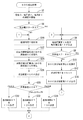
図6に、充放電停止状態における電圧値Vの変化を示す。図6に示すように、単電池14では、所定のSOC(図6では50%)までの放電が終了すると、放電終了後に単電池14の電圧値Vが比較的長い経過時間TをかけてOCVにまで上昇して収束する。そのため、電圧値Vを測定する経過時間Tが長くなるほど、電圧値VからOCVを精度良く推定することができ、推定されたOCVからSOCを精度良く推定することができる。従って、図8に示す第3対応表では、電圧値Vを測定する経過時間Tが長くなるほど、SOCの誤差値ΔCが小さく設定されている。
FIG. 6 shows a change in the voltage value V in the charge / discharge stop state. As shown in FIG. 6, in the
CPU70は、第3対応表に従って、合算誤差ΔCSが4%以上である場合、基準時間KTをT1に設定する(S30)。また、合算誤差ΔCSが3%以上4%未満である場合、基準時間KTをT2(>T1)に設定する(S32)。また、合算誤差ΔCSが3%未満である場合、基準時間KTをT3(>T2)に設定する(S34)。
When the sum error ΔCS is 4% or more according to the third correspondence table, the
次に、CPU70は、経過時間Tを基準時間KTと比較する(S36)。CPU70は、経過時間Tが基準時間KTより短い場合(S36:NO)、再度、充放電ステータスを確認する(S38)。CPU70は、単電池14が充放電停止状態に維持されている場合(S38:NO)、S36からの処理を繰り返す。
Next, the
一方、CPU70は、経過時間Tが基準時間KT以上になった場合(S36:YES)、経過時間Tが基準時間KT以上になるまでに測定された電圧値Vから、公知の手法を用いてOCVを推定する(S40)。CPU70は、メモリ76に記憶された第2対応表において、推定されたOCVに対応するSOCを選出し、選出したSOCを単電池14の充放電停止状態におけるSOC3として推定する(S42)。SOC3は、第1充電状態の別例である。
On the other hand, when the elapsed time T becomes equal to or greater than the reference time KT (S36: YES), the
また、CPU70は、第3対応表において基準時間KTに対応する誤差値ΔCの値を、単電池14の充放電停止状態における誤差値ΔC3として推定する。図8に示すように、第3対応表が誤差値ΔCの範囲として設定されている場合には、その最小値を誤差値ΔC3として推定しても良い。CPU70は、SOC3及び誤差値ΔC3を推定すると、電流積算値IN及び絶対積算値IZをリセットし(S44)、推定されたSOC3及び誤差値ΔC3をメモリ76に記憶する(S46)。誤差値ΔC3は、第1推定誤差の別例である。
Further, the
次に、CPU70は、基準時間KTを更新し、基準時間KTを現在設定されている時間より長い時間に設定する(S48)。CPU70は、基準時間KTがT1に設定されている場合、基準時間KTをT2に更新し(S50)、S36からの処理を繰り返す。また、基準時間KTがT2に設定されている場合、基準時間KTをT3に更新し(S52)、S36からの処理を繰り返す。
Next, the
S36からの処理において、CPU70は、経過時間Tが更新された基準時間KT以上になった場合(S36:YES)、再度、SOC3及び誤差値ΔC3を推定し、以前に記憶されたSOC3及び誤差値ΔC3に代えて、新たに推定されたSOC3及び誤差値ΔC3をメモリ76に上書きして記憶する(S46)。CPU70は、充放電停止状態が継続されている間に亘って、基準時間KTの更新を繰り返し、SOC3及び誤差値ΔC3の推定を繰り返す。
In the processing from S36, when the elapsed time T becomes equal to or greater than the updated reference time KT (S36: YES ), the
一方、基準時間KTがT3に設定されている場合、基準時間KTを現在設定されている時間より長い時間に設定することができない。CPU70は、この場合に、SOC3及び誤差値ΔC3の推定を停止し、単電池14の温度D及び電圧値Vの測定、及び組電池12の電流値Iの測定を終了する(S54)。CPU70は、BM62及びCS20を停止させてスリープ状態に移行し(S56)、SOC推定処理を終了する。
On the other hand, when the reference time KT is set to T3, the reference time KT cannot be set to a time longer than the currently set time. In this case, the
一方、CPU70は、経過時間Tが基準時間KT以下の場合であって(S36:NO)、且つ、電流値Iがゼロでなくなり、単電池14が充放電状態に切り替わると(S38:YES)、再びS6からS14で示す電流積算法を再び実行する。
On the other hand, when the elapsed time T is equal to or less than the reference time KT (S36: NO) and the current value I is not zero and the
3.本実施形態の効果
(1)本実施形態の電池パック60では、単電池14の充放電停止状態に実行される開放電圧法において、合算誤差ΔCSに基づいてSOCを推定する。
3. Advantages of the present embodiment (1) In the
開放電圧法では、単電池14のOCVの値からSOCを求めることから、推定される誤差値ΔCも現状の単電池14を反映した値となる。その一方、電流積算法では、電流センサ64の測定誤差に基づいて誤差値ΔCが推定されることから、推定される誤差値ΔCは、単電池14の誤差値ΔCの増減分を示す相対的なものとなる。そのため、単電池14の充放電状態が終了し、充放電停止状態に切り替わった際の誤差値ΔCは、当該充放電状態よりも前の充放電停止状態において推定された誤差値ΔCに、当該充放電状態において推定された誤差値ΔCを加えた合算誤差ΔCSとなる。
In the open-circuit voltage method, since the SOC is obtained from the OCV value of the
つまり、この電池パック60では、単電池14の充放電停止状態に実行される開放電圧法において、単電池14が充放電停止状態に切り替わった際の誤差値ΔCである合算誤差ΔCSに基づいてSOCを推定する。そのため、開放電圧法において推定されるSOCの誤差値ΔCを、合算誤差ΔCS以下とすること、つまり、合算誤差ΔCSよりも大きい誤差値ΔCを有するSOCが推定されることが抑制され、SOCを精度良く推定することができる。
That is, in this
(2)具体的には、開放電圧法において、SOCを推定するのに用いられる基準時間KTを合算誤差ΔCSに基づいて設定し、充放電停止からの経過時間Tが基準時間KT以上になった場合に、SOCを推定する。経過時間Tが基準時間KT以上になることで、推定されるSOCの誤差値ΔCは合算誤差ΔCSを下回ることから、充放電状態で推定されたSOCよりも精度の良いSOCを推定することができる。 (2) Specifically, in the open-circuit voltage method, the reference time KT used to estimate the SOC is set based on the total error ΔCS, and the elapsed time T from the charge / discharge stop is equal to or greater than the reference time KT. If so, the SOC is estimated. When the elapsed time T becomes equal to or longer than the reference time KT, the estimated SOC error value ΔC is less than the total error ΔCS, and therefore, it is possible to estimate the SOC with higher accuracy than the SOC estimated in the charge / discharge state. .
(3)本実施形態の電池パック60では、経過時間Tが合算誤差ΔCSに基づいて設定された基準時間KTを超えた場合には、基準時間KTを、現在設定されている時間より長い基準時間KTに更新して、再度、SOCを推定する。そのため、経過時間Tが、更新された基準時間KT以上になった場合には、合算誤差ΔCSに基づいて推定されたSOCよりも精度の良いSOCを推定することができる。
(3) In the
(4)本実施形態の電池パック60では、充放電停止状態が継続している間に亘って、基準時間KTの更新を繰り返し、SOCの推定を繰り返す。そのため、充放電停止状態が継続している間に亘って、SOCの推定精度を更に向上させることができる。
(4) In the
<実施形態2>
実施形態2について、図9、10を参照しつつ説明する。本実施形態の電池パック60では、単電池14が充放電停止状態から充放電状態に切り替わる際の目標誤差値ΔCMが予め定められている点で、実施形態1の電池パック60と異なる。以下の説明では、実施形態1と同一の内容については重複した記載を省略する。
<
The second embodiment will be described with reference to FIGS. The
1.SOC推定処理
本実施形態のSOC推定処理において、CPU70は、図9に示すように、充放電停止状態であることが検出されると、経過時間Tの計時を開始する(S20)に先立って、通信部28を用いて、充放電状態への移行を禁止する充放電禁止状態であることをBM62に送信する(S60)。充放電禁止状態であることを受信したBM62は、例えば電気自動車への電源の投入、あるいは電気自動車への充電開始等、ユーザによる操作が加えられたとしても、単電池14が充放電状態とならないように電池モジュール10を管理する。
1. SOC Estimation Process In the SOC estimation process of the present embodiment, as shown in FIG. 9, when it is detected that the charge / discharge stop state is detected, the
また、CPU70は、図10に示すように、経過時間Tを基準時間KTと比較し(S36)、経過時間Tが基準時間KTより短い場合(S36:NO)、現在までに推定されている誤差値ΔC(ΔC2、ΔC3)を目標誤差値ΔCMと比較する(S62)。CPU70は、現在までに推定されている誤差値ΔCが目標誤差値ΔCMよりも大きい場合(S62:NO)、充放電禁止状態を維持し、S36からの処理を繰り返す。
Further, as shown in FIG. 10, the
一方、CPU70は、現在までに推定されている誤差値ΔCが目標誤差値ΔCM以下となっている場合(S62:YES)、充放電状態への移行を許可する充放電許可状態となり、充放電許可状態であることをBM62に送信する(S66)。充放電許可状態であることを受信したBM62は、ユーザによる操作が加えられた場合に、当該操作に従って、単電池14を充放電状態に移行させる。
On the other hand, when the error value ΔC estimated to date is equal to or less than the target error value ΔCM (S62: YES), the
CPU70は、単電池14が充放電許可状態となると、充放電ステータスを確認する(S68)。CPU70は、電流値Iがゼロであり、単電池14が充放電停止状態に維持されている場合(S68:NO)、S36からの処理を繰り返す。一方、CPU70は、電流値Iがゼロでなくなり、単電池14が充放電状態に切り替わると(S68:YES)、再びS6からS14で示す電流積算法を再び実行する。
When the
2.本実施形態の効果
本実施形態のSOC推定処理では、単電池14の充放電停止状態において、推定されている誤差値ΔCが目標誤差値ΔCM以下となるまでは、充放電禁止状態を維持し、単電池14が充放電状態とならないようにする。そのため、単電池14が充放電許可状態となり、充放電状態に移行する際には、推定されるSOCの誤差値ΔCは目標誤差値ΔCMを下回ることから、精度の良いSOCを推定することができる。
2. Effects of the present embodiment In the SOC estimation processing of the present embodiment, the charge / discharge prohibited state is maintained until the estimated error value ΔC becomes equal to or less than the target error value ΔCM in the charge / discharge stop state of the
<実施形態3>
実施形態3について、図8、11、12を参照しつつ説明する。図8に示すように、本実施形態の第3対応表では、各単電池14の充放電停止からの経過時間Tと誤差値ΔCとの相関関係が記憶されているとともに、各単電池14の誤差値ΔCと電圧値Vの時間変化DVの相関関係が記憶されている。
<
A third embodiment will be described with reference to FIGS. As shown in FIG. 8, in the third correspondence table of the present embodiment, the correlation between the elapsed time T from the charge / discharge stop of each
図6に示すように、単電池14では、所定のSOCまでの放電が終了すると、放電終了後に単電池14の電圧値Vが比較的長い経過時間TをかけてOCVにまで上昇して収束し、その間、電圧値Vの時間変化DVはほぼ減少を続ける。そのため、時間変化DVの絶対値が小さくなるほど、OCVを精度良く推定することができ、推定されたOCVからSOCを精度良く推定することができる。従って、図8に示す第3対応表では、時間変化DVの絶対値が小さくなるほど、SOCの誤差値ΔCが小さく設定されている。
As shown in FIG. 6, in the
本実施形態の電池パック60では、合算誤差ΔCSに対応させて、経過時間Tとの比較に用いる基準時間KTを設定する代わりに、時間変化DVとの比較に用いる許容値KVを設定する点で、実施形態1の電池パック60と異なる。以下の説明では、実施形態1と同一の内容については重複した記載を省略する。
In the
1.SOC推定処理
本実施形態のSOC推定処理において、CPU70は、図11に示すように、合算誤差ΔCSを算出すると(S26)、メモリ76に記憶された第3対応表において、算出された合算誤差ΔCSに対応する時間変化DVを選出し、選出した時間変化DVを許容値KVに設定する(S28)。
1. SOC Estimation Process In the SOC estimation process of the present embodiment, when the
CPU70は、第3対応表に従って、合算誤差ΔCSが4%以上である場合、許容値KVをDV1に設定する(S70)。また、合算誤差ΔCSが3%以上4%未満である場合、許容値KVをDV2(<DV1)に設定する(S72)。また、合算誤差ΔCSが3%未満である場合、許容値KVをDV3(<DV2)に設定する(S74)。
If the sum error ΔCS is 4% or more according to the third correspondence table, the
次に、CPU70は、時間変化DVを許容値KVと比較する(S76)。CPU70は、時間変化DVが許容値KVより大きい場合(S76:NO)、再度、充放電ステータスを確認する(S38)。一方、時間変化DVが許容値KV以下になった場合(S76:YES)、時間変化DVが許容値KV以下になるまでに測定された電圧値Vから、公知の手法を用いてOCVを推定する(S40)。
Next, the
また、CPU70は、許容値KVを更新し、許容値KVを現在設定されている時間より小さい値に設定する(S78)。CPU70は、許容値KVがDV1に設定されている場合、許容値KVをDV2に更新し(S80)、S76からの処理を繰り返す。また、許容値KVがDV2に設定されている場合、許容値KVをDV3に更新し(S82)、S76からの処理を繰り返す。
Further, the
2.本実施形態の効果
(1)本実施形態の電池パック60では、開放電圧法において、SOCを推定するのに用いられる許容値KVを合算誤差ΔCSに基づいて設定し、電圧値Vの時間変化DVが許容値KV以下になった場合に、SOCを推定する。時間変化DVが許容値KV以下になることで、推定されるSOCの誤差値ΔCは合算誤差ΔCSを下回ることから、充放電状態で推定されたSOCよりも精度の良いSOCを推定することができる。
2. Advantages of the present embodiment (1) In the
(2)本実施形態の電池パック60では、時間変化DVが合算誤差ΔCSに基づいて設定された許容値KVを下回った場合には、許容値KVを、現在設定されている値より小さい許容値KVに更新して、再度、SOCを推定する。そのため、時間変化DVが、更新された許容値KV以下になった場合には、合算誤差ΔCSに基づいて推定されたSOCよりも精度の良いSOCを推定することができる。
(2) In the
<他の実施形態>
本明細書が開示する技術は上記記述及び図面によって説明した実施形態に限定されるものではなく、例えば次のような種々の態様も本発明の技術的範囲に含まれる。
(1)上記実施形態では、蓄電素子の一例として二次電池の単電池14を示したが、これに限らず、蓄電素子は、電気化学現象を伴うキャパシタ等であってもよい。
<Other embodiments>
The technology disclosed in the present specification is not limited to the embodiments described with reference to the above description and drawings, and for example, the following various aspects are also included in the technical scope of the present invention.
(1) In the above embodiment, the
(2)上記実施形態では、誤差値ΔC1と誤差値ΔC2から合算誤差ΔCSを算出する際に、誤差値ΔC1と誤差値ΔC2を加算して合算誤差ΔCSを算出する例を用いて説明を行ったが、合算誤差ΔCSの算出は必ずしもこの方法に限られない。例えば、誤差値ΔC1と誤差値ΔC2の2乗和平方根を合算誤差ΔCSとして算出してもよい。 (2) In the above embodiment, when the sum error ΔCS is calculated from the error value ΔC1 and the error value ΔC2, the explanation has been given using an example of calculating the sum error ΔCS by adding the error value ΔC1 and the error value ΔC2. However, the calculation of the total error ΔCS is not necessarily limited to this method. For example, the square sum of squares of the error value ΔC1 and the error value ΔC2 may be calculated as the sum error ΔCS.
(3)上記実施形態では、単電池14の充放電停止状態において、基準時間KTを更新する例を用いて説明を行ったが、基準時間KTの更新は必ずしも必要なものではなく、単電池14の充放電停止状態において、合算誤差ΔCSに基づく基準時間KTのみに基づいてSOCが推定されてもよい。
(3) In the above embodiment, the example in which the reference time KT is updated in the charge / discharge stop state of the
(4)また、基準時間KTが更新される場合であっても、その回数が制限されていてもよい。 (4) Further, even when the reference time KT is updated, the number of times may be limited.
(5)上記実施形態では、制御部の一例として、BM62に含まれる1つのCPU70を例示した。しかし、制御部は、複数のCPUを備える構成や、ASIC(Application Specific Integrated Circuit)などのハード回路を備える構成や、ハード回路及びCPUの両方を備える構成でもよい。要するに、制御部は、上記の充電状態推定処理を、ソフト処理またはハード回路を利用して実行するものであればよい。
(5) In the above embodiment, one
(6)上記実施形態では、CPU70が読み込んで実行するプログラムとして、メモリ76に記憶されたものを例に挙げた。しかし、プログラムは、これに限らず、ハードディスク装置、フラッシュメモリ(登録商標)などの不揮発性メモリや、CD−Rなどの記憶媒体などに記憶されたものでもよい。また、メモリ76は、必ずしもCPU70の内部に設けられる必要はなく、CPU70の外部に設けられていてもよい。
(6) In the above embodiment, the program stored in the
14:単電池、20:CS、24:電圧測定回路、30:センサユニット、64:電流センサ、76:メモリ、I:電流値、IN:電流積算値、IZ:絶対積算値、KT:基準時間、KV:許容値、T:経過時間、V:電圧値、ΔC:SOCの誤差値、ΔCS:合算誤差、DV:時間変化 14: Cell, 20: CS, 24: Voltage measurement circuit, 30: Sensor unit, 64: Current sensor, 76: Memory, I: Current value, IN: Current integrated value, IZ: Absolute integrated value, KT: Reference time , KV: allowable value, T: elapsed time, V: voltage value, ΔC: error value of SOC, ΔCS: total error, DV: time change
Claims (6)
前記蓄電素子の充放電停止からの経過時間と前記充電状態の推定誤差との第1相関関係が記憶された記憶部と、制御部と、を備え、
前記制御部は、
前記蓄電素子の充放電停止からの前記経過時間が所定の基準時間に達したことを条件に前記蓄電素子の端子電圧に基づき前記蓄電素子の充電状態を推定するとともに前記経過時間から前記第1相関関係に基づいてその充電状態の推定誤差を決定する第1推定処理と、
前記蓄電素子の充放電状態における充放電電流の積算値に基づき前記蓄電素子の充電状態を推定すると共にその充電状態の推定誤差を決定する第2推定処理と、を繰り返し実行し、
前記第1推定処理を前回に実行したときの推定誤差と前記第2推定処理を前回に実行したときの推定誤差とに基づいて算出した合算誤差が大きいほど次回の前記第1推定処理における前記基準時間を短く設定する、状態推定装置。 A state estimation device for estimating a state of charge of a storage element,
A storage unit that stores a first correlation between an elapsed time from the charge / discharge stop of the storage element and an estimation error of the state of charge, and a control unit,
The controller is
Estimating the state of charge of the electricity storage element based on the terminal voltage of the electricity storage element on the condition that the elapsed time from the charge / discharge stop of the electricity storage element has reached a predetermined reference time, and the first correlation from the elapsed time A first estimation process for determining an estimation error of the state of charge based on the relationship;
Repetitively executing a second estimation process for estimating a charge state of the power storage element based on an integrated value of a charge / discharge current in a charge / discharge state of the power storage element and determining an estimation error of the charge state;
The larger the total error calculated based on the estimation error when the first estimation process was executed last time and the estimation error when the second estimation process was executed last time, the larger the reference in the next first estimation process. A state estimation device that sets the time short .
前記制御部は、前記経過時間が前記基準時間に達したときには、前記第1推定処理を行ったあとに、前記基準時間を、前記第1推定処理の実行時の前記基準時間よりも長い時間に更新する、状態推定装置。 The state estimation device according to claim 1,
When the elapsed time reaches the reference time , the control unit sets the reference time to a time longer than the reference time at the time of execution of the first estimation process after performing the first estimation process. A state estimation device to be updated .
前記制御部は、前記第1推定処理において、前記蓄電素子が充放電状態になって前記第2推定処理が開始されるまでに、前記基準時間の更新と、前記第1推定処理の推定誤差の決定と、を繰り返し実行する、状態推定装置。 The state estimation device according to claim 2,
In the first estimation process, the control unit updates the reference time and the estimation error of the first estimation process before the second estimation process is started when the power storage element is in a charge / discharge state . A state estimation device that repeatedly executes determination .
前記制御部は、前記第1推定処理の推定誤差と前記第2推定処理の推定誤差とを足し合わせて前記合算誤差を算出する、状態推定装置。 The state estimation device according to any one of claims 1 to 3,
The said control part is a state estimation apparatus which adds the estimation error of a said 1st estimation process , and the estimation error of a said 2nd estimation process , and calculates the said total error.
前記記憶部は、前記充電状態の推定誤差と前記端子電圧の時間変化との第2相関関係が更に記憶され、
前記制御部は、前記第1推定処理において、
前記端子電圧と前記経過時間から前記端子電圧の時間変化を推定し、推定された前記端子電圧の時間変化が、前記合算誤差と前記第2相関関係から決定される許容値以下になった場合、前記経過時間が前記基準時間以上になったと推定し、
更に、前記端子電圧の時間変化が前記許容値以下になった場合、前記許容値を当該許容値よりも小さい値に更新し、前記端子電圧の時間変化が、更新された前記許容値に到達した場合、前記第1推定誤差を再度推定して更新する、状態推定装置。 The state estimation device according to any one of claims 1 to 4,
The storage unit further stores a second correlation between the estimation error of the state of charge and the time variation of the terminal voltage,
In the first estimation process, the control unit includes:
When the time change of the terminal voltage is estimated from the terminal voltage and the elapsed time, and the estimated time change of the terminal voltage is equal to or less than an allowable value determined from the sum error and the second correlation, Estimating that the elapsed time is equal to or greater than the reference time,
Further, when the time change of the terminal voltage becomes equal to or less than the allowable value, the allowable value is updated to a value smaller than the allowable value, and the time change of the terminal voltage reaches the updated allowable value. In this case, the state estimation device reestimates and updates the first estimation error.
前記蓄電素子の充放電停止からの経過時間が所定の基準時間に達したことを条件に前記蓄電素子の端子電圧に基づき前記蓄電素子の充電状態を推定するとともに前記経過時間から前記第1相関関係に基づいてその充電状態の推定誤差を決定する第1推定処理と、
前記蓄電素子の充放電状態における充放電電流の積算値に基づき前記蓄電素子の充電状態を推定すると共にその充電状態の推定誤差を決定する第2推定処理と、を繰り返し実行し、
前記第1推定処理を前回に実行したときの推定誤差と前記第2推定処理を前回に実行したときの推定誤差とに基づいて算出した合算誤差が大きいほど次回の前記第1推定処理における前記基準時間を短く設定する、状態推定方法。 A state estimation method for estimating a charge state of a storage element,
Estimating the state of charge of the electricity storage element based on the terminal voltage of the electricity storage element on the condition that the elapsed time from the charge / discharge stop of the electricity storage element has reached a predetermined reference time, and the first correlation from the elapsed time A first estimation process for determining an estimation error of the state of charge based on
Repetitively executing a second estimation process for estimating a charge state of the power storage element based on an integrated value of a charge / discharge current in a charge / discharge state of the power storage element and determining an estimation error of the charge state;
The larger the total error calculated based on the estimation error when the first estimation process was executed last time and the estimation error when the second estimation process was executed last time, the larger the reference in the next first estimation process. State estimation method that sets the time short .
Priority Applications (4)
| Application Number | Priority Date | Filing Date | Title |
|---|---|---|---|
| JP2013077474A JP6155774B2 (en) | 2013-04-03 | 2013-04-03 | State estimation device and state estimation method |
| CN201410116427.8A CN104101840B (en) | 2013-04-03 | 2014-03-26 | State estimating unit and state estimation method |
| EP14162635.8A EP2787361B1 (en) | 2013-04-03 | 2014-03-31 | State of charge estimation device and method of estimating state of charge |
| US14/242,341 US9983270B2 (en) | 2013-04-03 | 2014-04-01 | State of charge estimation device and method of estimating state of charge |
Applications Claiming Priority (1)
| Application Number | Priority Date | Filing Date | Title |
|---|---|---|---|
| JP2013077474A JP6155774B2 (en) | 2013-04-03 | 2013-04-03 | State estimation device and state estimation method |
Publications (2)
| Publication Number | Publication Date |
|---|---|
| JP2014202551A JP2014202551A (en) | 2014-10-27 |
| JP6155774B2 true JP6155774B2 (en) | 2017-07-05 |
Family
ID=50424051
Family Applications (1)
| Application Number | Title | Priority Date | Filing Date |
|---|---|---|---|
| JP2013077474A Active JP6155774B2 (en) | 2013-04-03 | 2013-04-03 | State estimation device and state estimation method |
Country Status (4)
| Country | Link |
|---|---|
| US (1) | US9983270B2 (en) |
| EP (1) | EP2787361B1 (en) |
| JP (1) | JP6155774B2 (en) |
| CN (1) | CN104101840B (en) |
Families Citing this family (13)
| Publication number | Priority date | Publication date | Assignee | Title |
|---|---|---|---|---|
| US11144106B2 (en) | 2015-04-13 | 2021-10-12 | Semiconductor Components Industries, Llc | Battery management system for gauging with low power |
| WO2017110578A1 (en) * | 2015-12-25 | 2017-06-29 | ローム株式会社 | Current monitoring circuit and coulomb counter circuit, and battery management system and motor vehicle using same |
| JP6830318B2 (en) * | 2016-01-15 | 2021-02-17 | 株式会社Gsユアサ | Power storage element management device, power storage element module, vehicle and power storage element management method |
| WO2017130673A1 (en) * | 2016-01-29 | 2017-08-03 | 日立オートモティブシステムズ株式会社 | Cell state estimation device, cell control device, cell system, and cell state estimation method |
| EP3411262B1 (en) * | 2016-02-02 | 2020-12-30 | Toyota Motor Europe | Control device and method for charging a rechargeable battery |
| JP5980459B1 (en) * | 2016-03-30 | 2016-08-31 | 本田技研工業株式会社 | Power supply apparatus, transport apparatus having the power supply apparatus, estimation method for estimating correlation information between charging rate of storage unit and open-circuit voltage, and program for estimating correlation information |
| CN106597309B (en) * | 2016-12-19 | 2019-03-15 | 先进储能材料国家工程研究中心有限责任公司 | The vehicle-mounted both ends Ni-MH power cell packet SOC modification method |
| US10522881B1 (en) | 2018-01-12 | 2019-12-31 | Cora Aero Llc | Estimation of self discharge rate as a measure of battery health |
| JP2019132765A (en) * | 2018-02-01 | 2019-08-08 | 株式会社デンソー | Battery monitoring device |
| CN109355218A (en) * | 2018-10-18 | 2019-02-19 | 东北农业大学 | It is rapidly heated the Multifunctional fermentation composite bacteria agent and the preparation method and application thereof of taste removal for livestock excrement composting |
| CN112311075B (en) * | 2019-07-29 | 2022-06-24 | 广州汽车集团股份有限公司 | Solar-energy-based automobile energy storage control method and device and automobile |
| DE102021209542A1 (en) * | 2021-08-31 | 2023-03-02 | Robert Bosch Gesellschaft mit beschränkter Haftung | Method for determining a state of charge of an electrical energy store, electrical energy store and device |
| CN114506244B (en) * | 2022-01-28 | 2023-05-23 | 重庆长安新能源汽车科技有限公司 | Estimation method and estimation system for charging remaining time of electric automobile |
Family Cites Families (21)
| Publication number | Priority date | Publication date | Assignee | Title |
|---|---|---|---|---|
| JP3767150B2 (en) * | 1998-01-09 | 2006-04-19 | 日産自動車株式会社 | Battery remaining capacity detection device |
| JP3997646B2 (en) | 1999-04-05 | 2007-10-24 | 株式会社デンソー | Battery remaining capacity calculation method |
| JP4239435B2 (en) * | 2001-06-04 | 2009-03-18 | トヨタ自動車株式会社 | Battery capacity determination method and battery capacity determination device |
| JP4228760B2 (en) * | 2002-07-12 | 2009-02-25 | トヨタ自動車株式会社 | Battery charge state estimation device |
| KR100669470B1 (en) * | 2005-12-22 | 2007-01-16 | 삼성에스디아이 주식회사 | Method of compensating soc for battery and battery management system using the same |
| KR100669477B1 (en) * | 2005-12-22 | 2007-01-16 | 삼성에스디아이 주식회사 | Method adjusting soc for battery and battery management system using the same |
| JP4984527B2 (en) * | 2005-12-27 | 2012-07-25 | トヨタ自動車株式会社 | Secondary battery charge state estimation device and charge state estimation method |
| JP4910423B2 (en) | 2006-02-27 | 2012-04-04 | ソニー株式会社 | Battery pack, electronic device, and battery remaining amount detection method |
| JP4872743B2 (en) | 2007-03-23 | 2012-02-08 | トヨタ自動車株式会社 | Secondary battery state estimation device |
| DE102008041546A1 (en) * | 2008-08-26 | 2010-03-04 | Robert Bosch Gmbh | Method for calculating the state of charge of a battery |
| JP2011106952A (en) | 2009-11-17 | 2011-06-02 | Honda Motor Co Ltd | Method for estimating residual capacity of battery |
| JP2011169831A (en) | 2010-02-19 | 2011-09-01 | Mitsumi Electric Co Ltd | Device and method for detection of battery state |
| JP5520657B2 (en) | 2010-03-30 | 2014-06-11 | 古河電気工業株式会社 | CHARGE RATE ESTIMATION METHOD, CHARGE RATE ESTIMATION DEVICE, AND SECONDARY BATTERY POWER SUPPLY SYSTEM |
| JP5640477B2 (en) * | 2010-06-08 | 2014-12-17 | マツダ株式会社 | Battery remaining capacity detection method and detection apparatus |
| JP5771909B2 (en) | 2010-06-08 | 2015-09-02 | 日産自動車株式会社 | Secondary battery charge capacity estimation device |
| JP2012002660A (en) | 2010-06-16 | 2012-01-05 | Toshiba Corp | Secondary battery device |
| JP2012057998A (en) | 2010-09-07 | 2012-03-22 | Calsonic Kansei Corp | Charge rate calculation apparatus for secondary battery and charge rate calculation method |
| US8452556B2 (en) * | 2010-09-22 | 2013-05-28 | GM Global Technology Operations LLC | Method and apparatus for estimating SOC of a battery |
| JP5641215B2 (en) | 2010-10-19 | 2014-12-17 | 三菱自動車工業株式会社 | Secondary battery control device |
| JP5432931B2 (en) | 2011-01-18 | 2014-03-05 | カルソニックカンセイ株式会社 | Battery charge rate estimation device |
| JP5318128B2 (en) | 2011-01-18 | 2013-10-16 | カルソニックカンセイ株式会社 | Battery charge rate estimation device |
-
2013
- 2013-04-03 JP JP2013077474A patent/JP6155774B2/en active Active
-
2014
- 2014-03-26 CN CN201410116427.8A patent/CN104101840B/en active Active
- 2014-03-31 EP EP14162635.8A patent/EP2787361B1/en active Active
- 2014-04-01 US US14/242,341 patent/US9983270B2/en active Active
Also Published As
| Publication number | Publication date |
|---|---|
| JP2014202551A (en) | 2014-10-27 |
| EP2787361A1 (en) | 2014-10-08 |
| CN104101840B (en) | 2018-06-22 |
| US9983270B2 (en) | 2018-05-29 |
| CN104101840A (en) | 2014-10-15 |
| EP2787361B1 (en) | 2018-11-21 |
| US20140303914A1 (en) | 2014-10-09 |
Similar Documents
| Publication | Publication Date | Title |
|---|---|---|
| JP6155774B2 (en) | State estimation device and state estimation method | |
| JP5994521B2 (en) | State estimation device, open-circuit voltage characteristics generation method | |
| JP6351852B2 (en) | Lithium ion battery state of charge estimation method and lithium ion battery state of charge estimation device | |
| JP6300000B2 (en) | Charge state estimation device, charge state estimation method | |
| JP6714838B2 (en) | State estimation device and state estimation method | |
| JP6119402B2 (en) | Internal resistance estimation device and internal resistance estimation method | |
| EP3106892B1 (en) | State estimation device and state estimation method | |
| JP6155830B2 (en) | State estimation device and state estimation method | |
| JP6066163B2 (en) | Open circuit voltage estimation device, state estimation device, and open circuit voltage estimation method | |
| JP5929778B2 (en) | CHARGE RATE ESTIMATION DEVICE AND CHARGE RATE ESTIMATION METHOD | |
| JP6867478B2 (en) | Battery control and vehicle system | |
| JP6156216B2 (en) | Full charge capacity estimation device | |
| JP2020514680A (en) | Device and method for estimating capacity retention rate of secondary battery | |
| JP5911407B2 (en) | Battery soundness calculation device and soundness calculation method | |
| JP5851514B2 (en) | Battery control device, secondary battery system | |
| JP2014109535A (en) | Internal resistance estimation device, charging apparatus, discharging apparatus, and internal resistance estimation method | |
| JP5999409B2 (en) | State estimation device and state estimation method | |
| JP4794986B2 (en) | Remaining capacity calculation device and battery pack | |
| JP2014059251A (en) | Internal resistance estimation device and internal resistance estimation method | |
| JP2013029445A (en) | Battery management device and power supply system | |
| JP6062919B2 (en) | Method for optimal charging of electrochemical batteries | |
| WO2014038555A1 (en) | Battery state-of-charge detection device, battery system, battery state-of-charge detection method, and program | |
| JPWO2020250342A1 (en) | Charge / discharge control device and charge / discharge control method | |
| JP7169917B2 (en) | SECONDARY BATTERY CONTROL DEVICE AND SECONDARY BATTERY CONTROL METHOD |
Legal Events
| Date | Code | Title | Description |
|---|---|---|---|
| A621 | Written request for application examination |
Free format text: JAPANESE INTERMEDIATE CODE: A621 Effective date: 20160127 |
|
| A977 | Report on retrieval |
Free format text: JAPANESE INTERMEDIATE CODE: A971007 Effective date: 20161128 |
|
| A131 | Notification of reasons for refusal |
Free format text: JAPANESE INTERMEDIATE CODE: A131 Effective date: 20161206 |
|
| A521 | Written amendment |
Free format text: JAPANESE INTERMEDIATE CODE: A523 Effective date: 20170131 |
|
| TRDD | Decision of grant or rejection written | ||
| A01 | Written decision to grant a patent or to grant a registration (utility model) |
Free format text: JAPANESE INTERMEDIATE CODE: A01 Effective date: 20170509 |
|
| A61 | First payment of annual fees (during grant procedure) |
Free format text: JAPANESE INTERMEDIATE CODE: A61 Effective date: 20170522 |
|
| R150 | Certificate of patent or registration of utility model |
Ref document number: 6155774 Country of ref document: JP Free format text: JAPANESE INTERMEDIATE CODE: R150 |