EP2107143A2 - Bobbin or tube holder for a bobbin or tube transport device on a textile machine - Google Patents
Bobbin or tube holder for a bobbin or tube transport device on a textile machine Download PDFInfo
- Publication number
- EP2107143A2 EP2107143A2 EP20090000912 EP09000912A EP2107143A2 EP 2107143 A2 EP2107143 A2 EP 2107143A2 EP 20090000912 EP20090000912 EP 20090000912 EP 09000912 A EP09000912 A EP 09000912A EP 2107143 A2 EP2107143 A2 EP 2107143A2
- Authority
- EP
- European Patent Office
- Prior art keywords
- sliding
- coil
- wall
- annular
- sleeve carrier
- Prior art date
- Legal status (The legal status is an assumption and is not a legal conclusion. Google has not performed a legal analysis and makes no representation as to the accuracy of the status listed.)
- Withdrawn
Links
Images


Classifications
-
- D—TEXTILES; PAPER
- D01—NATURAL OR MAN-MADE THREADS OR FIBRES; SPINNING
- D01H—SPINNING OR TWISTING
- D01H9/00—Arrangements for replacing or removing bobbins, cores, receptacles, or completed packages at paying-out or take-up stations ; Combination of spinning-winding machine
- D01H9/18—Arrangements for replacing or removing bobbins, cores, receptacles, or completed packages at paying-out or take-up stations ; Combination of spinning-winding machine for supplying bobbins, cores, receptacles, or completed packages to, or transporting from, paying-out or take-up stations ; Arrangements to prevent unwinding of roving from roving bobbins
-
- B—PERFORMING OPERATIONS; TRANSPORTING
- B65—CONVEYING; PACKING; STORING; HANDLING THIN OR FILAMENTARY MATERIAL
- B65H—HANDLING THIN OR FILAMENTARY MATERIAL, e.g. SHEETS, WEBS, CABLES
- B65H67/00—Replacing or removing cores, receptacles, or completed packages at paying-out, winding, or depositing stations
- B65H67/06—Supplying cores, receptacles, or packages to, or transporting from, winding or depositing stations
- B65H67/064—Supplying or transporting cross-wound packages, also combined with transporting the empty core
-
- B—PERFORMING OPERATIONS; TRANSPORTING
- B65—CONVEYING; PACKING; STORING; HANDLING THIN OR FILAMENTARY MATERIAL
- B65H—HANDLING THIN OR FILAMENTARY MATERIAL, e.g. SHEETS, WEBS, CABLES
- B65H2701/00—Handled material; Storage means
- B65H2701/30—Handled filamentary material
- B65H2701/31—Textiles threads or artificial strands of filaments
Definitions
- the invention relates to a bobbin or sleeve carrier for a bobbin and tube transport system on a textile machine, wherein the bobbin or sleeve carrier comprises a pin arranged on a base for receiving an empty sleeve or a bobbin, and the base body includes a carrier base, with which the Coil or sleeve carrier directly or indirectly slidably rests on the support surface of a conveyor track of the transport system.
- Coil or sleeve transport systems for the removal of the cops or the coils of and for feeding empty tubes to textile machines, such as spinning machines or winders, are well known.
- the coil or sleeve carriers are normally called peg trays, also called peg trays, which are slidably guided on conveyor tracks designed as carrier rails. Ie. the peg slides slide during their movement towards the work stations or away from the work stations on the mounting rails.
- the mounting rails take on at least a portion of the weight of the loaded with coils or sleeves peg slide.
- the peg slides are thereby pushed or pulled over the conveyor track by means of carriers attached to a conveyor.
- the conveying means are, for example, belts, in particular steel belts, cables or chains, which are guided or also driven by deflection means, in particular deflection rollers.
- the drivers which move the pintle carriages along the conveyor track, i. push, are attached to the conveyor and are moved by this. For this purpose, each pin slide is picked up and guided by its own driver.
- Bobbin carriers move a higher total weight along the transport path.
- the static friction when starting the transport device claimed the conveyor drive extremely strong.
- Object of the present invention is therefore to propose a coil or sleeve carrier for a bobbin or tube transport device of a long textile machines, thanks to which without complex design measures and without increasing the power of the drives, the performance of the transport system is improved.
- the object is achieved in that on the carrier base partially or full surface a sliding pad of high abrasion resistance and high lubricity is applied, which consists of a different material than the main body.
- the sliding pad on the coil or sleeve carrier is preferably made of a thermoplastic, and more preferably of a polyamide (PA), such as PA6, PA66, PA11, PA12, PA46, PA6-G or a copolyamide or polyamide blend.
- PA polyamide
- the polyamides mentioned may be provided with or without additionally integrated solid lubricants or lubricant additives or have a MoS 2 or graphite modification.
- amorphous plastics modified with lubricant additives such as PC, PMMA, PVC-U, ABS or PS are also suitable, even if they do not necessarily achieve the excellent sliding and wear behavior of PA 66.
- the peg carriage includes a body, z. B. in plate form, on which a pin for receiving sleeves or coils or cops is arranged.
- the main body includes a carrier base, which rests on the support surface of the conveyor track.
- the conveyor track is preferably a mounting rail in the form of a sheet metal or extrusion profile made of metal, in particular of aluminum.
- the mounting rail forms a bearing surface for the pin slides.
- the support surface is preferably flat. It can be formed horizontally or inclined.
- a rail support in particular made of plastic, which forms a sliding surface for the journal slide, can be arranged.
- the sliding pad of the journal slide can be one or more parts.
- the slide pad can enter into a cloth, force and / or positive connection with the carrier underside. Combinations of the aforementioned connection forms are therefore also possible.
- the underside of the carrier may be partially or fully covered with the sliding pad.
- the base body is a one-sided or two-sided, at least to the support surface of the conveyor path open hollow body with a preferably annular outer wall, which includes a common cavity or more by one or more webs or inner walls of separate sub-cavities, also called chambers includes ,
- the sliding pad is preferably a partially or completely embedded in the cavity of the body slider.
- the slider is preferably formed in its outer contour opposite to the said cavity. It is fastened by means of form and / or material connection in the cavity.
- the slider protrudes a little at the bottom of the main body, so that the coil or sleeve carrier rests with the slider and not with its underside of the support surface.
- the said projection can, for. B. be 0.1 to 2 mm.
- the projection should not be too large, otherwise the position settings of the gripper and other components coming into contact with the trunnion would have to be changed because of the change in the height of the trunnion carriage in the case of retrofitted transport systems.
- a wear-resistant material for the sliding pad a comparatively slight elevation of the stated order of magnitude is completely sufficient.
- the outer wall of the base body is annular.
- annular outer wall Within the annular outer wall, an annular or polygonal, self-contained inner wall is arranged, which encloses an open central cavity.
- the sliding pad can now be a, in the central cavity of the body partially or completely sunken slider.
- the slider is preferably formed in its outer contour opposite to the said cavity. It is fastened by means of form and / or material connection in the cavity. The slider protrudes a little at the bottom of the main body, so that the coil or sleeve carrier rests with the slider and not with its underside of the support surface
- the base body has an annular outer wall and an inner, preferably concentrically arranged to the outer wall, annular inner wall, which encloses an open central cavity.
- the sliding pad can now be partially or completely embedded in the central cavity.
- the slider in its outer contour is preferably formed opposite to the central cavity. It is fastened by means of form and / or material connection in the cavity.
- Said sliding body may be an annular body or a solid body.
- the slider can be provided with radial excess, which can be introduced by radial compression in the corresponding cavity in the body and is positively trapped by radial relief of the ring body under spring back because of the restoring force in the cavity.
- the sliding pad may be an annular slider with an annular gap and resilient properties.
- the slider is designed here in the functional design of an inner locking ring. That the slider is inserted by radially compressing the annular gap in a preferably circular or annular cavity in the body and and sets by radial relief of the ring body due to the restoring force of the annular leg form-fitting firmly on the inner wall of the cavity.
- the positive connection or in addition to the positive connection can also be a material connection, for.
- a material connection for.
- the base body and the slider are already connected to each other during the manufacturing process. So z. B. the main body are molded in an injection molding together with the slider in a two-component injection molding.
- the sliding body can also be connected as an insert during the injection molding process for the production of the main body with this.
- the sliding body can also be screwed into the cavity in the base body via a screw connection.
- the slider may also be formed conically for the purpose of producing a positive connection transverse to the radial extent.
- a clip or snap-in connection between the body and slider is conceivable.
- a plurality of radially inwardly spaced and spaced apart recessed connecting webs are arranged between the annular outer wall and the annular inner wall, which connect the outer wall with the annular inner wall and effect in this way a reinforcement of the structure of the base body
- the sliding pad can now be an annular sliding body, which is arranged resting on the recessed connecting webs between the outer wall and the inner wall. It can now be provided both between the outer wall and the inner wall, as just described, as well as in the central cavity, as described above, a sliding body according to one of the embodiments described above. But it can also be provided at the appropriate place only a slider.
- the sliding surface or the base body of the underside of the base body in each case before, so that the pin carriage rests with the sliding body of the support surface of the support rail or conveyor track.
- the sliding surface may be the main body, i. the outer and / or inner wall project by about 0.1 to 0.2 mm.
- the main body or the entire pin slide consist of a plastic, preferably of a thermoplastic material, such as.
- a plastic preferably of a thermoplastic material, such as.
- a polyester PBT or PET.
- journal slide according to the invention can be used in transport systems on spinning machines, in particular ring spinning machines, twisting machines or winding machines.
- the sliding pad according to the invention on the trunnion carriage considerably reduces the friction between the conveyor track and the trunnion carriage, so that, despite an increase of moving trunnion carriages in the case of long spinning machines, no increase in the drive power is required and the energy consumption can be further optimized. Moreover, the good sliding properties, in particular the excellent dry friction properties, of the wear-resistant sliding pad are retained over a long service life.
- the friction coefficient of more than 0.4 ⁇ , in particular 0.44 ⁇ can be reduced to less than 0.3 ⁇ , in particular to 0.23 ⁇ .
- the present invention also has the advantages that the pin carrier can be equipped in a simple manner and with little technical and economic effort with a low-friction and wear-resistant sliding surface. In this case, recourse can be had to the conventional form of the trunnion carriage without having to laboriously modify it. This therefore also allows the retrofitting of countless already in circulation peg slide with a low-friction and wear-resistant sliding surface.
- the spinning machine or the conveyor, supplies the carriers or the coils to a "sink” and receives carriers or sleeves from a "source”.
- the "sink” and the "source” can by a single processing unit, for. As a winder, are formed. But they can also be formed by entry or exit points of a transport system that can work automatically, semi-automatically or even hand-operated.
- the transport system delivers z. B. coils to predetermined or indefinite points and receives sleeves from the same or even from other places.
- the Fig. 1 shows a schematic plan view of a ring spinning machine 1 with a guided around the ring spinning endless conveyor.
- the ring spinning machine 1 has on opposite machine sides parallel to each other spinning stations groups 12a and 12b, each consisting of only schematically indicated spinning stations 11. Further details of the ring spinning machine 1, in particular the machine heads are not shown, because it is so far the usual and known arrangements. The number of spinning units 11 is reproduced greatly reduced for the sake of clarity.
- the two spinning station groups 12a, 12b is designed as an endless conveyor conveyor 21 guided around in the form of a vertically extending steel strip.
- the steel strip is placed around deflection rollers 13, 14, 15, 16 with a vertical axis at the two ends of the parallel and in alignment with each other spin groups 12a, 12b.
- deflection rollers 13, 14, 15, 16 with a vertical axis at the two ends of the parallel and in alignment with each other spin groups 12a, 12b.
- pin slides 2 are arranged one behind the other at a distance and in contact with the driving fingers, which according to Fig. 2 from a circular disk-shaped main body 3 (plate) and a sleeve journal arranged perpendicular thereto 4, and preferably in the region of an arranged between the sleeve pin 4 and the base body 3 widened foot 9 are engaged behind by the driving fingers 10.
- sleeve changing devices 20 which may be formed as in classic Doffern and serve to remove from the spindles of the spinning units 11 full sleeves (cops or spools) and instead choircken empty tubes on the spindles, which by means of the endless conveyor 21 to the individual spinning units eleventh have been introduced.
- a conveying connection (not shown) to a winding unit or a cop removing and receiving unit can be provided.
- the guide rail 6 is arranged on or on the machine frame.
- The, preferably designed as a hollow profile guide rail 6 comprises a flat, horizontally oriented guide or support surface 7, on which a band-shaped plastic sliding pad can be arranged.
- the peg slide 2 is slidably guided with its arranged on the underside of the base body 3 slide pad 5 on the support surface 7 and the plastic pad thereon ( Fig. 2 ).
- the pin slide 2 has between the pin 4 and the base 3 a slightly opposite the pin 4 widened foot 9, which is engaged behind by a driving finger 10.
- the driver finger 10 is connected via a holding arm with the carrier body 22 of the driver 8, which is fastened with fastening means on the vertical conveyor belt 21.
- the driver 8 is guided via guide means along the guide rail 6.
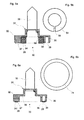
- Fig. 3 shows the bottom view of a known pin slide 31 as shown in Fig. 4a .
- 5a and 6a is also shown in cross-sectional view.
- the base body 32 is a hollow body which is open on one side, facing the bearing surface, with an annular outer wall 35 and has a lower side 30.
- an annular outer wall 34 Within the annular outer wall 34 is an annular, arranged concentrically to the outer wall and self-contained inner wall 36 is arranged, which encloses an open central cavity 29.
- the central cavity 29 has, to the side opposite the underside an opening through which the pin 33 is fixed to the base body 32.
- this feature is not relevant to the present invention and is therefore not intended to be limiting.
- the first embodiment according to Fig. 4a and 4b shows the pin carriage 31 with a slider 34.
- the slider 34 is in the form of a circular solid body. This is completely embedded up to a front-side stop 39 in the central cavity 29 of the body 32 and sits in this form-fitting firmly.
- the sliding body is formed in its outer contour opposite to the central cavity, wherein the base body 32 may have a small radial excess relative to the cavity.
- the slider 32 is connected by means of a form and / or material connection with the base body 32.
- the second embodiment according to Fig. 5a and 5b shows the pin carriage 31 with a slider 54.
- the slider 54 is an annular body with annular gap 59, which in its outer contour relative to the cavity 29 has a radial excess.
- the slider is designed here in the functional design of an inner locking ring, which is insertable by radial compression of the annular gap 59 in the annular cavity 29 in the base body 32 and by radial relief of the annular body by spring back form-fitting manner on the inner wall of the cavity 29 determines.
- the slider 54 is completely embedded up to an end stop 39 in the central cavity 29 of the body 32.
- the third embodiment according to Fig. 6a and 6b shows the pin carriage 31 with a slider 74.
- the slider 74 is an annular, flat body which rests between the outer wall 35 and the inner wall 36 on the recessed connecting webs 37. Since the connecting webs 37 are set back, the sliding body 74 extends beyond the supporting edge of the underside into the main body 32.
- the slider 74 is z. B. glued to the main body 32.
- the sliding body 31 is according to the embodiments according to 4 to 6 at the bottom of the body 32 slightly before, so that the coil or sleeve support 31 rests with the sliding surface 28 of the slider 34, 54, 74 and not with the end edges of its support bottom 30 of the support surface.
Abstract
Description
Die Erfindung betrifft einen Spulen- oder Hülsenträger für ein Spulen- und Hülsentransportsystem an einer Textilmaschine, wobei der Spulen- oder Hülsenträger einen auf einem Grundkörper angeordneten Zapfen zur Aufnahme einer leeren Hülse oder einer Garnspule enthält, und der Grundkörper eine Trägerunterseite enthält, mit welcher der Spulen- oder Hülsenträger direkt oder indirekt auf der Auflagefläche einer Förderbahn des Transportsystems gleitend verschiebbar aufliegt.The invention relates to a bobbin or sleeve carrier for a bobbin and tube transport system on a textile machine, wherein the bobbin or sleeve carrier comprises a pin arranged on a base for receiving an empty sleeve or a bobbin, and the base body includes a carrier base, with which the Coil or sleeve carrier directly or indirectly slidably rests on the support surface of a conveyor track of the transport system.
Spulen- bzw. Hülsentransportsysteme zum Abtransport der Kopse bzw. der Spulen von sowie zum Zuführen leerer Hülsen zu Textilmaschinen, wie Spinnmaschinen oder Spulmaschinen, sind hinreichend bekannt. So beschreiben beispielsweise die
Die Zapfenschlitten werden dabei mittels, an einem Fördermittel befestigten Mitnehmer über die Förderbahn geschoben oder gezogen. Die Fördermittel sind beispielsweise Bänder, insbesondere Stahlbänder, Seile oder Ketten, welche über Umlenkmittel, insbesondere Umlenkrollen, geführt bzw. auch angetrieben werden. Die Mitnehmer, welche die Zapfenschlitten entlang der Förderbahn fortbewegen, d.h. schieben, sind an den Fördermitteln befestigt und werden durch diese bewegt. Dazu wird zweckmässig jeder Zapfenschlitten durch einen eigenen Mitnehmer aufgenommen und geführt.The peg slides are thereby pushed or pulled over the conveyor track by means of carriers attached to a conveyor. The conveying means are, for example, belts, in particular steel belts, cables or chains, which are guided or also driven by deflection means, in particular deflection rollers. The drivers which move the pintle carriages along the conveyor track, i. push, are attached to the conveyor and are moved by this. For this purpose, each pin slide is picked up and guided by its own driver.
Mit zunehmender Anzahl Spinnstellen pro Spinnmaschine werden auch die Förderbahnen immer länger und die Anzahl der Hülsen- bzw. Spulenträger wird immer grösser. Die Fördermittel müssen folglich in der Lage sein, eine grosse Anzahl Hülsen- bzw. Spulenträger zu transportieren. Hierbei sieht sich der Konstrukteur mit zwei Problemen konfrontiert. Einerseits müssen die Fördermittel durch die grössere Anzahl Hülsen- bzw.With increasing number of spinning stations per spinning machine and the conveyor tracks are getting longer and the number of sleeve or coil carrier is getting bigger. The conveying means must therefore be able to transport a large number of sleeve or coil carrier. Here, the designer faces two problems. On the one hand, the funding by the greater number of sleeve or
Spulenträger ein höheres Gesamtgewicht entlang der Transportbahn bewegen. Andererseits wachsen mit der Anzahl bewegter Hülsen- bzw. Spulenträger auch die durch die gleitende Führung der Hülsen- bzw. Spulenträger auf der Förderbahn entstehenden Reibungswiderstände. Insbesondere die Haftreibung beim Starten der Transporteinrichtung beansprucht den Fördermittelantrieb ausserordentlich stark.Bobbin carriers move a higher total weight along the transport path. On the other hand grow with the number of moving sleeve or coil carrier and the friction caused by the sliding guide of the sleeve or coil carrier on the conveyor track friction. In particular, the static friction when starting the transport device claimed the conveyor drive extremely strong.
Die zunehmende Belastung bzw. Überlastung der Antriebe führt zu vermehrtem Schlupf und zu einer entsprechend erhöhten Abnützung an den Kraftübertragungsstellen, z. B. zwischen Antriebsrad und Förderband.The increasing load or overload of the drives leads to increased slippage and to a correspondingly increased wear on the power transmission points, z. B. between the drive wheel and conveyor belt.
Grundsätzlich lassen sich die genannten Probleme durch die Verwendung leistungsstärkerer Antriebe sowie von robusteren Fördermittel beseitigen. Ein solches Vorgehen bedingt jedoch eine konstruktive Überarbeitung des Transportsystems mit entsprechenden Kostenfolgen. Leistungsstärkere Antriebe sowie robustere Komponenten verteuern jedoch die Textilmaschine zusätzlich und führen überdies zu einer Erhöhung des Energieverbrauchs, so dass neben den Fertigungskosten auch die Betriebskosten steigen.In principle, the problems mentioned can be eliminated by using more powerful drives and more robust conveying equipment. However, such a procedure requires a constructive revision of the transport system with corresponding cost consequences. However, more powerful drives and more robust components make the textile machine more expensive and, moreover, lead to an increase in energy consumption, so that in addition to the manufacturing costs, the operating costs also increase.
Aufgabe vorliegender Erfindung ist es daher, einen Spulen- oder Hülsenträger für eine Spulen- bzw. Hülsentransportvorrichtung einer langen Textilmaschinen vorzuschlagen, dank welchem ohne aufwändige konstruktive Massnahmen sowie ohne Erhöhung der Leistungskraft der Antriebe die Leistungsfähigkeit des Transportsystems verbessert wird.Object of the present invention is therefore to propose a coil or sleeve carrier for a bobbin or tube transport device of a long textile machines, thanks to which without complex design measures and without increasing the power of the drives, the performance of the transport system is improved.
Die Aufgabe wird dadurch gelöst, dass auf der Trägerunterseite teil- oder vollflächig eine Gleitunterlage von hoher Abriebfestigkeit und hoher Gleitfähigkeit aufgebracht ist, welche aus einem anderen Material als der Grundkörper besteht.The object is achieved in that on the carrier base partially or full surface a sliding pad of high abrasion resistance and high lubricity is applied, which consists of a different material than the main body.
Die Gleitunterlage am Spulen- oder Hülsenträger, nachfolgend der Einfachheit halber Zapfenschlitten genannt, besteht bevorzugt aus einem thermoplastischen Kunststoff, und besonders bevorzugt aus einem Polyamid (PA), wie PA6, PA66, PA11, PA12, PA46, PA6-G oder aus einem Copolyamid oder Polyamid-Blend. Die genannten Polyamide können ohne oder mit zusätzlich integrierten Festschmierstoffen bzw. Gleitmittelzusätzen versehen sein oder eine MoS2- oder Graphit-Modifikation aufweisen.The sliding pad on the coil or sleeve carrier, hereinafter referred to simply as a slide pin, is preferably made of a thermoplastic, and more preferably of a polyamide (PA), such as PA6, PA66, PA11, PA12, PA46, PA6-G or a copolyamide or polyamide blend. The polyamides mentioned may be provided with or without additionally integrated solid lubricants or lubricant additives or have a MoS 2 or graphite modification.
Ferner eignen sich auch die nachfolgend aufgelisteten Kunststoffe für Gleitunterlagen:
- Polyacetalharze, wie Polyoxymethylen (POM, POM-H, POM-K), mit oder ohne zusätzlich integrierten Festschmierstoffen, bzw. Gleitmittelzusätzen; bzw. mit einer MoS2- oder Graphit-Modifikation;
- Polyethylen (PE), PE-UHMW (ultrahochmolekular), PE-HMW (hochmolekular);
- thermoplastische Polyester, wie PBT oder PET, mit oder ohne zusätzlich integrierten Festschmierstoffen, bzw. Gleitmittelzusätzen; bzw. mit MoS2- oder Graphit-Modifikation;
- Hochleistungs-Kunststoffe, wie PI, PAI, PEEK, PAEK, mit oder ohne zusätzlich integrierten Festschmierstoffen, bzw. Gleitmittelzusätzen, bzw. mit MoS2- oder Graphit-Modifikation;
- PTFE (Polytetrafluorethylen).
- Polyacetal resins, such as polyoxymethylene (POM, POM-H, POM-K), with or without additionally integrated solid lubricants, or lubricant additives; or with a MoS 2 or graphite modification;
- Polyethylene (PE), PE-UHMW (ultra-high molecular weight), PE-HMW (high molecular weight);
- thermoplastic polyesters, such as PBT or PET, with or without additionally integrated solid lubricants or lubricant additives; or with MoS 2 or graphite modification;
- High-performance plastics such as PI, PAI, PEEK, PAEK, with or without additionally integrated solid lubricants or lubricant additives, or with MoS 2 or graphite modification;
- PTFE (polytetrafluoroethylene).
Ferner eignen sich auch mit Gleitmittelzusätzen modifizierte amorphe Kunststoffe, wie PC, PMMA, PVC-U, ABS oder PS, auch wenn diese nicht unbedingt das hervorragende Gleit- und Verschleissverhalten von PA 66 erreichen.Furthermore, amorphous plastics modified with lubricant additives, such as PC, PMMA, PVC-U, ABS or PS are also suitable, even if they do not necessarily achieve the excellent sliding and wear behavior of PA 66.
Der Zapfenschlitten enthält einen Grundkörper, z. B. in Tellerform, auf welchem ein Zapfen zur Aufnahme von Hülsen bzw. Spulen oder Kopsen angeordnet ist. Der Grundkörper enthält eine Trägerunterseite, welche der Auflagefläche der Förderbahn aufliegt.The peg carriage includes a body, z. B. in plate form, on which a pin for receiving sleeves or coils or cops is arranged. The main body includes a carrier base, which rests on the support surface of the conveyor track.
Die Förderbahn ist bevorzugt eine Tragschiene in Form eines Blech- oder Extrusionsprofils aus Metall, insbesondere aus Aluminium. Die Tragschiene bildet eine Auflagefläche für die Zapfenschlitten aus. Die Auflagefläche ist bevorzugt eben ausgebildet. Sie kann horizontal oder geneigt ausgebildet sein.The conveyor track is preferably a mounting rail in the form of a sheet metal or extrusion profile made of metal, in particular of aluminum. The mounting rail forms a bearing surface for the pin slides. The support surface is preferably flat. It can be formed horizontally or inclined.
Zwischen der Auflagefläche der Tragschiene und den Zapfenschlitten kann eine Schienenauflage, insbesondere aus Kunststoff, welche eine Gleitfläche für die Zapfenschlitten ausbildet, angeordnet sein.Between the bearing surface of the support rail and the journal slide, a rail support, in particular made of plastic, which forms a sliding surface for the journal slide, can be arranged.
Die Gleitunterlage des Zapfenschlittens kann ein- oder mehrteilig sein. Die Gleitunterlage kann mit der Trägerunterseite eine Stoff-, Kraft- und/oder Formschlussverbindung eingehen. Kombinationen der vorgenannten Verbindungsformen sind also auch möglich.The sliding pad of the journal slide can be one or more parts. The slide pad can enter into a cloth, force and / or positive connection with the carrier underside. Combinations of the aforementioned connection forms are therefore also possible.
Die Trägerunterseite kann teil- oder vollflächig mit der Gleitunterlage abgedeckt sein.The underside of the carrier may be partially or fully covered with the sliding pad.
In einer bevorzugten Ausführungsform ist der Grundkörper ein ein- oder zweiseitig, wenigstens zur Auflagefläche der Förderbahn hin offener Hohlkörper mit einer vorzugsweise ringförmigen Aussenwand, welche einen gemeinsamen Hohlraum oder mehrere durch einen oder mehrere Stege bzw. Innenwände voneinander getrennte Teilhohlräume, auch Kammern genannt, einschliesst.In a preferred embodiment, the base body is a one-sided or two-sided, at least to the support surface of the conveyor path open hollow body with a preferably annular outer wall, which includes a common cavity or more by one or more webs or inner walls of separate sub-cavities, also called chambers includes ,
Die Gleitunterlage ist vorzugsweise ein teilweise oder vollständig in den Hohlraum des Grundkörpers eingelassener Gleitkörper. Der Gleitkörper ist in seiner Aussenkontur bevorzugt gegengleich zum genannten Hohlraum ausgebildet. Er wird mittels Form- und/oder Stoffschluss im Hohlraum befestigt. Der Gleitkörper steht an der Unterseite des Grundkörpers etwas vor, so dass der Spulen- oder Hülsenträger mit dem Gleitkörper und nicht mit seiner Unterseite der Auflagefläche aufliegt. Der genannte Vorsprung kann z. B. 0.1 bis 2 mm betragen. Der Vorsprung sollte nicht allzu gross sein, da sonst bei nachgerüsteten Transportsystemen die Positionseinstellungen der Greifer und anderer mit dem Zapfenschlitten in Verbindung tretenden Bauteilen wegen der Veränderung der Höhenlage des Zapfenschlittens geändert werden müssten. Ferner reicht bei einem verschleissfesten Material für die Gleitunterlage eine vergleichsweise geringe Überhöhung der genannten Grössenordnung vollkommen aus.The sliding pad is preferably a partially or completely embedded in the cavity of the body slider. The slider is preferably formed in its outer contour opposite to the said cavity. It is fastened by means of form and / or material connection in the cavity. The slider protrudes a little at the bottom of the main body, so that the coil or sleeve carrier rests with the slider and not with its underside of the support surface. The said projection can, for. B. be 0.1 to 2 mm. The projection should not be too large, otherwise the position settings of the gripper and other components coming into contact with the trunnion would have to be changed because of the change in the height of the trunnion carriage in the case of retrofitted transport systems. Furthermore, in the case of a wear-resistant material for the sliding pad, a comparatively slight elevation of the stated order of magnitude is completely sufficient.
In Weiterbildung der Erfindung ist die Aussenwand des Grundkörpers ringförmig. Innerhalb der ringförmigen Aussenwand ist eine ringförmige oder polygonale, in sich geschlossene Innenwand angeordnet, welche einen offenen zentralen Hohlraum einschliesst. Die Gleitunterlage kann nun ein, in den zentralen Hohlraum des Grundkörpers teilweise oder vollständig eingelassener Gleitkörper sein. Der Gleitkörper ist in seiner Aussenkontur bevorzugt gegengleich zum genannten Hohlraum ausgebildet. Er wird mittels Form- und/oder Stoffschluss im Hohlraum befestigt. Der Gleitkörper steht an der Unterseite des Grundkörpers etwas vor, so dass der Spulen- oder Hülsenträger mit dem Gleitkörper und nicht mit seiner Unterseite der Auflagefläche aufliegtIn a further development of the invention, the outer wall of the base body is annular. Within the annular outer wall, an annular or polygonal, self-contained inner wall is arranged, which encloses an open central cavity. The sliding pad can now be a, in the central cavity of the body partially or completely sunken slider. The slider is preferably formed in its outer contour opposite to the said cavity. It is fastened by means of form and / or material connection in the cavity. The slider protrudes a little at the bottom of the main body, so that the coil or sleeve carrier rests with the slider and not with its underside of the support surface
In einer besonders bevorzugten Ausführung weist der Grundkörper eine ringförmige Aussenwand und eine innere, vorzugsweise konzentrisch zur Aussenwand angeordnete, ringförmige Innenwand auf, welche einen offenen zentralen Hohlraum einschliesst.In a particularly preferred embodiment, the base body has an annular outer wall and an inner, preferably concentrically arranged to the outer wall, annular inner wall, which encloses an open central cavity.
Die Gleitunterlage kann nun teilweise oder vollständig in den zentralen Hohlraum eingelassen sein. Auch hier ist der Gleitkörper in seiner Aussenkontur bevorzugt gegengleich zum zentralen Hohlraum ausgebildet. Er wird mittels Form- und/oder Stoffschluss im Hohlraum befestigt.The sliding pad can now be partially or completely embedded in the central cavity. Again, the slider in its outer contour is preferably formed opposite to the central cavity. It is fastened by means of form and / or material connection in the cavity.
Der besagte Gleitkörper kann ein ringförmiger Körper oder ein Vollkörper sein. Der Gleitkörper kann mit radialem Übermass versehen sein, welcher durch radiales Zusammendrücken in den entsprechenden Hohlraum im Grundkörper einführbar ist und durch radiale Entlastung des Ringkörpers unter Rückfederung wegen der Rückstellkraft formschlüssig im Hohlraum festsitzt.Said sliding body may be an annular body or a solid body. The slider can be provided with radial excess, which can be introduced by radial compression in the corresponding cavity in the body and is positively trapped by radial relief of the ring body under spring back because of the restoring force in the cavity.
Ferner kann die Gleitunterlage ein ringförmiger Gleitkörper mit Ringspalt und federelastischen Eigenschaften sein. Der Gleitkörper ist hier in der funktionellen Ausführung eines Innensicherungsringes konzipiert. D.h. der Gleitkörper ist durch radiales Zusammendrücken des Ringspaltes in einen vorzugsweise kreis- oder ringförmigen Hohlraum im Grundkörper einführbar und und legt sich durch radiale Entlastung des Ringkörpers aufgrund der Rückstellkraft der Ringschenkel formschlüssig an der Innenwand des Hohlraums fest.Furthermore, the sliding pad may be an annular slider with an annular gap and resilient properties. The slider is designed here in the functional design of an inner locking ring. That the slider is inserted by radially compressing the annular gap in a preferably circular or annular cavity in the body and and sets by radial relief of the ring body due to the restoring force of the annular leg form-fitting firmly on the inner wall of the cavity.
Alternativ zum Formschluss oder zusätzlich zum Formschluss kann auch ein Stoffschluss, z. B. eine Klebverbindung, zwischen dem Grundkörper und dem Gleitkörper vorgesehen sein. Es ist auch denkbar, dass der Grundkörper und der Gleitkörper bereits beim Herstellungsprozess miteinander verbunden werden. So kann z. B. der Grundkörper in einem Spritzgiessverfahren zusammen mit dem Gleitkörper in einem Zweikomponentenspritzgiessverfahren gegossen werden. Ferner kann der Gleitkörper auch kann als Einlegeteil während des Spritzgiessverfahrens zur Herstellung des Grundkörpers mit diesem verbunden werden.Alternatively to the positive connection or in addition to the positive connection can also be a material connection, for. As an adhesive bond, be provided between the body and the slider. It is also conceivable that the base body and the slider are already connected to each other during the manufacturing process. So z. B. the main body are molded in an injection molding together with the slider in a two-component injection molding. Furthermore, the sliding body can also be connected as an insert during the injection molding process for the production of the main body with this.
Ferner kann der Gleitkörper auch über eine Schraubverbindung in den Hohlraum im Grundkörper hinein eingeschraubt sein. Der Gleitkörper kann ferner zwecks Herstellung eines Formschlusses quer zur radialen Ausdehnung auch konisch ausgebildet sein. Im weiteren ist auch eine Clip- bzw. Schnappverschlussverbindung zwischen Grundkörper und Gleitkörper denkbar.Furthermore, the sliding body can also be screwed into the cavity in the base body via a screw connection. The slider may also be formed conically for the purpose of producing a positive connection transverse to the radial extent. In addition, a clip or snap-in connection between the body and slider is conceivable.
In einer Weiterbildung der besonders bevorzugten Ausführungsform des Grundkörpers sind zwischen der ringförmigen Aussenwand und der ringförmigen Innenwand mehrere radial und in Abstand zueinander angeordnete gegen innen zurückgesetzte Verbindungsstege angeordnet, welche die Aussenwand mit der ringförmigen Innenwand verbinden und auf diese Weise eine Verstärkung der Struktur des Grundkörpers bewirken. Die Gleitunterlage kann nun ein ringförmiger Gleitkörper sein, welcher zwischen der Aussenwand und der Innenwand auf den zurückgesetzten Verbindungsstegen aufliegend angeordnet ist. Es kann nun sowohl zwischen der Aussenwand und der Innenwand, wie eben beschrieben, als auch im zentralen Hohlraum, wie weiter oben beschrieben, ein Gleitkörper gemäss einer der oben beschriebenen Ausführungsformen vorgesehen sein. Es kann aber auch nur ein Gleitkörper an entsprechender Stelle vorgesehen sein.In a further development of the particularly preferred embodiment of the base body, a plurality of radially inwardly spaced and spaced apart recessed connecting webs are arranged between the annular outer wall and the annular inner wall, which connect the outer wall with the annular inner wall and effect in this way a reinforcement of the structure of the base body , The sliding pad can now be an annular sliding body, which is arranged resting on the recessed connecting webs between the outer wall and the inner wall. It can now be provided both between the outer wall and the inner wall, as just described, as well as in the central cavity, as described above, a sliding body according to one of the embodiments described above. But it can also be provided at the appropriate place only a slider.
Grundsätzlich steht die Gleitfläche bzw. der Grundkörper der Unterseite des Grundkörpers jeweils vor, so dass der Zapfenschlitten mit dem Gleitkörper der Auflagefläche der Trägerschiene bzw. Förderbahn aufliegt. Die Gleitfläche kann den Grundkörper, d.h. die Aussen- und/oder Innenwand um rund 0.1 bis 0.2 mm überragen.Basically, the sliding surface or the base body of the underside of the base body in each case before, so that the pin carriage rests with the sliding body of the support surface of the support rail or conveyor track. The sliding surface may be the main body, i. the outer and / or inner wall project by about 0.1 to 0.2 mm.
Der Grundkörper bzw. der gesamte Zapfenschlitten bestehen aus einem Kunststoff, vorzugsweise aus einem thermoplastischen Kunststoff, wie z. B. einem Polyester (PBT oder PET). So kann z. B. der Zapfenschlitten aus einem Polyester, insbesondere PBT, und die Gleitunterlage am Zapfenschlitten aus einem Polyamid, insbesondere PA 66, sein.The main body or the entire pin slide consist of a plastic, preferably of a thermoplastic material, such as. As a polyester (PBT or PET). So z. B. the pin slide of a polyester, in particular PBT, and the sliding pad on the pin slide of a polyamide, in particular PA 66, be.
Der erfindungsgemässe Zapfenschlitten ist einsetzbar in Transportsystemen an Spinnmaschinen, insbesondere Ringspinnmaschinen, Zwirnmaschinen oder Spulmaschinen.The journal slide according to the invention can be used in transport systems on spinning machines, in particular ring spinning machines, twisting machines or winding machines.
Die erfindungsgemässe Gleitunterlage am Zapfenschlitten reduziert die Reibung zwischen Förderbahn und Zapfenschlitten erheblich, so dass trotz einer Zunahme von bewegten Zapfenschlitten bei langen Spinnmaschinen keine Erhöhung der Antriebsleistung erforderlich ist und der Energieverbrauch weiter optimiert werden kann. Die guten Gleiteigenschaften, insbesondere die hervorragenden Trockenreibungseigenschaften, der verschleissfesten Gleitunterlage bleiben überdies über eine lange Betriebsdauer erhalten.The sliding pad according to the invention on the trunnion carriage considerably reduces the friction between the conveyor track and the trunnion carriage, so that, despite an increase of moving trunnion carriages in the case of long spinning machines, no increase in the drive power is required and the energy consumption can be further optimized. Moreover, the good sliding properties, in particular the excellent dry friction properties, of the wear-resistant sliding pad are retained over a long service life.
Dank der erfindungsgemässen Gleitunterlage kann der Reibungskoeffizient von über 0.4 µ, insbesondere von 0.44 µ, auf unter 0.3 µ, insbesondere auf bis 0.23 µ, herabgesetzt werden.Thanks to the sliding pad according to the invention, the friction coefficient of more than 0.4 μ, in particular 0.44 μ, can be reduced to less than 0.3 μ, in particular to 0.23 μ.
Die vorliegende Erfindung weist ferner die Vorteile auf, dass die Zapfenträger auf einfache Weise und mit wenig technischem und wirtschaftlichem Aufwand zusätzlich mit einer reibungsarmen und verschleissfesten Gleitfläche ausgerüstet werden können. Dabei kann auf die herkömmliche Form der Zapfenschlitten zurückgegriffen werden, ohne dass diese aufwändig modifiziert werden müsste. Dies erlaubt daher auch das Nachrüsten der unzähligen bereits heute im Umlauf befindlichen Zapfenschlitten mit einer reibungsarmen und verschleissfesten Gleitfläche.The present invention also has the advantages that the pin carrier can be equipped in a simple manner and with little technical and economic effort with a low-friction and wear-resistant sliding surface. In this case, recourse can be had to the conventional form of the trunnion carriage without having to laboriously modify it. This therefore also allows the retrofitting of countless already in circulation peg slide with a low-friction and wear-resistant sliding surface.
Die nachfolgende Beschreibung der Erfindung anhand von Ausführungsbeispielen ist auf Aspekte bezogen, welche im Zusammenhang mit dem Hülsen- bzw. Spulentransport an der Ringspinnmaschine stehen. Der Vollständigkeit halber sei aber erwähnt, dass die Spinnmaschine, bzw. das Fördermittel, die Träger bzw. die Spulen an eine "Senke" liefert und Träger bzw. Hülsen von einer "Quelle" erhält. Die "Senke" und die "Quelle" können durch eine einzige Weiterverarbeitungseinheit, z. B. eine Spulmaschine, gebildet werden. Sie können aber auch durch Ein- bzw. Ausgangsstellen eines Transportsystems gebildet werden, das automatisch, teilautomatisch oder sogar handbedient arbeiten kann. Das Transportsystem liefert z. B. Spulen an im Voraus bestimmte oder unbestimmte Stellen und erhält Hülsen von den gleichen oder sogar von anderen Stellen zurück.The following description of the invention with reference to embodiments is based on aspects related to the sleeve or coil transport to the ring spinning machine. For the sake of completeness, however, it should be mentioned that the spinning machine, or the conveyor, supplies the carriers or the coils to a "sink" and receives carriers or sleeves from a "source". The "sink" and the "source" can by a single processing unit, for. As a winder, are formed. But they can also be formed by entry or exit points of a transport system that can work automatically, semi-automatically or even hand-operated. The transport system delivers z. B. coils to predetermined or indefinite points and receives sleeves from the same or even from other places.
Die Erfindung wird nachfolgend anhand der
- Fig. 1:
- eine schematische Draufsicht einer Ringspinnmaschine mit einem um diese herumgeführten Endlosförderer;
- Fig. 2:
- einen Querschnitt durch einen auf einer Trägerschiene geführten Zapfenschlitten;
- Fig. 3:
- eine Draufsicht der Unterseite eines Zapfenschlittens;
- Fig. 4a,b:
- einen Schnitt durch einen Zapfenschlitten gemäss einer ersten Ausführungsform;
- Fig. 5a, b:
- einen Schnitt durch einen Zapfenschlitten gemäss einer zweiten Ausführungsform;
- Fig. 6a, b:
- einen Schnitt durch einen Zapfenschlitten gemäss einer dritten Ausführungsform.
- Fig. 1:
- a schematic plan view of a ring spinning machine with a guided around this endless conveyor;
- Fig. 2:
- a cross section through a guided on a support rail pin slide;
- 3:
- a plan view of the underside of a pin slide;
- Fig. 4a, b:
- a section through a pin slide according to a first embodiment;
- Fig. 5a, b:
- a section through a pin slide according to a second embodiment;
- Fig. 6a, b:
- a section through a pin slide according to a third embodiment.
Die
Um die beiden Spinnstellengruppen 12a, 12b ist ein als Endlosförderer ausgebildetes Fördermittel 21 in Form eines vertikal verlaufenden Stahlbandes herumgeführt. Das Stahlband ist an den beiden Enden der parallel und in Ausrichtung zueinander verlaufenden Spinnstellengruppen 12a, 12b um Umlenkrollen 13, 14, 15, 16 mit vertikaler Achse herumgelegt. Es liegen somit zwei sich entlang jeweils einer Spinnstellengruppe 12a bzw. 12b erstreckende lange Trümer und zwei die beiden Spinnstellengruppen 12a, 12b an den Enden verbindende kurze Trümer des Endlosförderers 21 vor.To the two spinning
Am Fördermittel 21 sind, ausgerichtet mit den einzelnen Spinnstellen 11, sich vom Endlosförderer 21 nach aussen erstreckende, jeweils einen sich quer zur Förderrichtung erstreckenden Mitnehmerfinger 10 aufweisende Mitnehmer 8 befestigt. Unmittelbar neben und unter dem Endlosförderer 21 erstreckt sich im Bereich der Spinnstellengruppen 12a, 12b eine horizontale Tragschiene 6, die gemäss dieser Ausführung auch um das linke Ende der Ringspinnmaschine 1 parallel zum Endlosförderer 21 herumgeführt ist, um eine Transportverbindung zwischen den beiden Seiten der Ringspinnmaschine herzustellen.On the
Auf der Tragschiene 6 sind hintereinander in Abstand und in Anlage mit den Mitnehmerfingern 10 Zapfenschlitten 2 angeordnet, welche gemäss
An beiden Maschinenseiten sind nach
An einem Ende der Spinnstellengruppen 12a, 12b kann eine Förderverbindung (nicht gezeigt) zu einer Spuleinheit oder einer Kops-Entnahme- und Hülsen-Bestückungseinheit vorgesehen sein.At one end of the spinning
Die Führungsschiene 6 ist auf dem bzw. am Maschinenrahmen angeordnet. Die, vorzugsweise als Hohlprofil ausgebildete Führungsschiene 6 umfasst eine ebene, horizontal ausgerichtete Führungs- bzw. Auflagefläche 7, auf welcher eine bandförmige Kunststoffgleitunterlage angeordnet sein kann. Der Zapfenschlitten 2 ist mit seiner auf der Unterseite des Grundkörpers 3 angeordneten Gleitunterlage 5 gleitend auf der Auflagefläche 7 bzw. der darauf befindlichen Kunststoffunterlage geführt (
Der Zapfenschlitten 2 weist zwischen dem Zapfen 4 und dem Grundkörper 3 einen etwas gegenüber dem Zapfen 4 verbreiterten Fuss 9 auf, welcher von einem Mitnehmerfinger 10 hintergriffen wird. Der Mitnehmerfinger 10 ist über einen Haltearm mit dem Trägerkörper 22 des Mitnehmers 8 verbunden, welcher mit Befestigungsmitteln am vertikalen Förderband 21 befestigt ist. Der Mitnehmer 8 ist über Führungsmittel entlang der Führungsschiene 6 geführt.The
Ausgehend von dieser vorgegebenen Struktur des Grundkörpers 32 werden nachfolgend drei Ausführungsformen eines Zapfenschlittens 31 mit Gleitunterlage 34, 54, 74 beschrieben.Starting from this predetermined structure of the
Die erste Ausführungsform gemäss
Die zweite Ausführungsform gemäss
Die dritte Ausführungsform gemäss
Der Gleitkörper 31 steht gemäss den Ausführungsbeispielen nach
Claims (12)
dadurch gekennzeichnet, dass
auf der Trägerunterseite (30) teil- oder vollflächig eine Gleitunterlage (34, 54, 74) von hoher Abriebfestigkeit und hoher Gleitfähigkeit aufgebracht ist, welche aus einem anderen Material als der Grundkörper (32) besteht.Coil or sleeve carrier (31) for a bobbin and tube transport system (1) on a textile machine, wherein the bobbin or sleeve carrier (31) comprises a pin (33) arranged on a base body (32) for receiving an empty tube or bobbin , and the base body (32) has a carrier underside (30) for slidingly displaceable direct or indirect support of the reel or sleeve carrier (31) on the bearing surface (7) of a conveyor track (6) of the transport system (1),
characterized in that
on the underside of the carrier (30) partially or over the entire surface of a sliding pad (34, 54, 74) of high abrasion resistance and high lubricity is applied, which consists of a different material than the base body (32).
Applications Claiming Priority (1)
| Application Number | Priority Date | Filing Date | Title |
|---|---|---|---|
| CH4522008 | 2008-03-25 |
Publications (1)
| Publication Number | Publication Date |
|---|---|
| EP2107143A2 true EP2107143A2 (en) | 2009-10-07 |
Family
ID=40974629
Family Applications (1)
| Application Number | Title | Priority Date | Filing Date |
|---|---|---|---|
| EP20090000912 Withdrawn EP2107143A2 (en) | 2008-03-25 | 2009-01-23 | Bobbin or tube holder for a bobbin or tube transport device on a textile machine |
Country Status (2)
| Country | Link |
|---|---|
| EP (1) | EP2107143A2 (en) |
| CN (1) | CN101545161A (en) |
Cited By (1)
| Publication number | Priority date | Publication date | Assignee | Title |
|---|---|---|---|---|
| CN115928342A (en) * | 2023-01-09 | 2023-04-07 | 河北力科纺织有限责任公司 | Bobbin yarn post-treatment process equipment |
Families Citing this family (9)
| Publication number | Priority date | Publication date | Assignee | Title |
|---|---|---|---|---|
| CN103498222A (en) * | 2013-09-22 | 2014-01-08 | 慈溪在业机械制造有限公司 | High-strength and abrasion-resisting embedded convex disc |
| CN103668595A (en) * | 2013-11-20 | 2014-03-26 | 慈溪在业机械制造有限公司 | Novel embedded type abrasion resistant convex disc |
| CN103668601B (en) * | 2013-11-30 | 2015-12-02 | 天津宏大纺织机械有限公司 | For the movable creel of thickness connection induction system |
| DE102014001779A1 (en) * | 2014-02-12 | 2015-08-13 | Atlantic C Handels- Und Beratungs-Gmbh | Device for storing filament bobbins |
| CN104047104B (en) * | 2014-07-01 | 2016-05-04 | 苏州万图明电子软件有限公司 | Multi-functional automatic weaving loom |
| CN105316817A (en) * | 2015-11-04 | 2016-02-10 | 经纬纺织机械股份有限公司 | Collective doffing gear block steel belt guide mechanism of ring spinning frame |
| CN105386172B (en) * | 2015-12-04 | 2018-08-28 | 晋中经纬泓鑫机械有限公司 | A kind of conveying spool device and method |
| CN109353880B (en) * | 2018-08-31 | 2024-04-12 | 杭州锐冠科技有限公司 | Carry aluminium alloy and bobbin yarn conveyor |
| CN110106587A (en) * | 2019-05-10 | 2019-08-09 | 经纬智能纺织机械有限公司 | A kind of fixed device of lower bracket of ring throstle steel band type pallet conveying |
Citations (2)
| Publication number | Priority date | Publication date | Assignee | Title |
|---|---|---|---|---|
| WO1990003460A1 (en) | 1988-09-24 | 1990-04-05 | Maschinenfabrik Rieter Ag | Spinning frame with endless conveyor |
| EP0517668A1 (en) | 1991-06-02 | 1992-12-09 | Maschinenfabrik Rieter Ag | Transporting bobbins or bobbin tubes in spinning machines |
-
2009
- 2009-01-23 EP EP20090000912 patent/EP2107143A2/en not_active Withdrawn
- 2009-03-20 CN CN200910129815A patent/CN101545161A/en active Pending
Patent Citations (2)
| Publication number | Priority date | Publication date | Assignee | Title |
|---|---|---|---|---|
| WO1990003460A1 (en) | 1988-09-24 | 1990-04-05 | Maschinenfabrik Rieter Ag | Spinning frame with endless conveyor |
| EP0517668A1 (en) | 1991-06-02 | 1992-12-09 | Maschinenfabrik Rieter Ag | Transporting bobbins or bobbin tubes in spinning machines |
Cited By (1)
| Publication number | Priority date | Publication date | Assignee | Title |
|---|---|---|---|---|
| CN115928342A (en) * | 2023-01-09 | 2023-04-07 | 河北力科纺织有限责任公司 | Bobbin yarn post-treatment process equipment |
Also Published As
| Publication number | Publication date |
|---|---|
| CN101545161A (en) | 2009-09-30 |
Similar Documents
| Publication | Publication Date | Title |
|---|---|---|
| EP2107143A2 (en) | Bobbin or tube holder for a bobbin or tube transport device on a textile machine | |
| EP1905875B1 (en) | Bobbin transportation arrangement for spinning machines | |
| DE60005792T2 (en) | THREAD CHANGING DEVICE WITH CAM FOLLOWER FOR WINDING A REEL | |
| DE60021735T2 (en) | TRANSFER OF OBJECTS BETWEEN PROMOTED TRANSFERS | |
| EP1194622B1 (en) | Thread-supplying device for textile machines | |
| EP3279117A1 (en) | Conveyor system for conveying conveyed goods | |
| EP2034060A1 (en) | Textile machine with a drafting unit | |
| EP2776348B1 (en) | Conveyor system with a conveyor chain, and carrying segment for a conveyor carrier of a conveyor chain | |
| EP3529180B1 (en) | Conveying system | |
| DE1954261A1 (en) | Swiveling roller pressure device | |
| DD287538A5 (en) | HAENGEFOERDERSYSTEM | |
| DE3407804A1 (en) | REEL TRANSPORT DEVICE | |
| WO1995025056A1 (en) | Mono-or twin-rail overhead chain conveyor | |
| DE202013007959U1 (en) | Door striker for an elevator door | |
| DE202007011954U1 (en) | Drawframe and lower roller bearing carriage | |
| EP0506994A1 (en) | Belt-driven roller-conveyor | |
| DE102017217721A1 (en) | Passenger conveyor with roller and roller guide of the step chain and method for guiding a step chain with rollers and protective rollers | |
| DE102006011558A1 (en) | Driven roller conveyor curve and conveyor track with such a roller conveyor curve | |
| DE3432245C2 (en) | ||
| WO2019110323A1 (en) | Raceway, conveyor device, and method for mounting a raceway | |
| EP1059214B1 (en) | Transporting device | |
| DE102010046573B4 (en) | Method and device for feeding a plastic material to an extruder screw | |
| EP0964183B1 (en) | Belt for producing a cotton wool roll | |
| DE19540177C2 (en) | conveyor system | |
| EP2437992A1 (en) | Conveying apparatus for transporting piece goods |
Legal Events
| Date | Code | Title | Description |
|---|---|---|---|
| PUAI | Public reference made under article 153(3) epc to a published international application that has entered the european phase |
Free format text: ORIGINAL CODE: 0009012 |
|
| AK | Designated contracting states |
Kind code of ref document: A2 Designated state(s): AT BE BG CH CY CZ DE DK EE ES FI FR GB GR HR HU IE IS IT LI LT LU LV MC MK MT NL NO PL PT RO SE SI SK TR |
|
| AX | Request for extension of the european patent |
Extension state: AL BA RS |
|
| STAA | Information on the status of an ep patent application or granted ep patent |
Free format text: STATUS: THE APPLICATION IS DEEMED TO BE WITHDRAWN |
|
| 18D | Application deemed to be withdrawn |
Effective date: 20120801 |