EP2106772A1 - Verfahren zur herstellung von einweg-windeln vom höschentyp - Google Patents
Verfahren zur herstellung von einweg-windeln vom höschentyp Download PDFInfo
- Publication number
- EP2106772A1 EP2106772A1 EP07832033A EP07832033A EP2106772A1 EP 2106772 A1 EP2106772 A1 EP 2106772A1 EP 07832033 A EP07832033 A EP 07832033A EP 07832033 A EP07832033 A EP 07832033A EP 2106772 A1 EP2106772 A1 EP 2106772A1
- Authority
- EP
- European Patent Office
- Prior art keywords
- web
- chassis
- regions
- region
- machine direction
- Prior art date
- Legal status (The legal status is an assumption and is not a legal conclusion. Google has not performed a legal analysis and makes no representation as to the accuracy of the status listed.)
- Granted
Links
Images


Classifications
-
- A—HUMAN NECESSITIES
- A61—MEDICAL OR VETERINARY SCIENCE; HYGIENE
- A61F—FILTERS IMPLANTABLE INTO BLOOD VESSELS; PROSTHESES; DEVICES PROVIDING PATENCY TO, OR PREVENTING COLLAPSING OF, TUBULAR STRUCTURES OF THE BODY, e.g. STENTS; ORTHOPAEDIC, NURSING OR CONTRACEPTIVE DEVICES; FOMENTATION; TREATMENT OR PROTECTION OF EYES OR EARS; BANDAGES, DRESSINGS OR ABSORBENT PADS; FIRST-AID KITS
- A61F13/00—Bandages or dressings; Absorbent pads
- A61F13/15—Absorbent pads, e.g. sanitary towels, swabs or tampons for external or internal application to the body; Supporting or fastening means therefor; Tampon applicators
- A61F13/15577—Apparatus or processes for manufacturing
- A61F13/15699—Forming webs by bringing together several webs, e.g. by laminating or folding several webs, with or without additional treatment of the webs
-
- A—HUMAN NECESSITIES
- A61—MEDICAL OR VETERINARY SCIENCE; HYGIENE
- A61F—FILTERS IMPLANTABLE INTO BLOOD VESSELS; PROSTHESES; DEVICES PROVIDING PATENCY TO, OR PREVENTING COLLAPSING OF, TUBULAR STRUCTURES OF THE BODY, e.g. STENTS; ORTHOPAEDIC, NURSING OR CONTRACEPTIVE DEVICES; FOMENTATION; TREATMENT OR PROTECTION OF EYES OR EARS; BANDAGES, DRESSINGS OR ABSORBENT PADS; FIRST-AID KITS
- A61F13/00—Bandages or dressings; Absorbent pads
- A61F13/15—Absorbent pads, e.g. sanitary towels, swabs or tampons for external or internal application to the body; Supporting or fastening means therefor; Tampon applicators
- A61F13/45—Absorbent pads, e.g. sanitary towels, swabs or tampons for external or internal application to the body; Supporting or fastening means therefor; Tampon applicators characterised by the shape
- A61F13/49—Absorbent articles specially adapted to be worn around the waist, e.g. diapers
- A61F13/496—Absorbent articles specially adapted to be worn around the waist, e.g. diapers in the form of pants or briefs
-
- A—HUMAN NECESSITIES
- A61—MEDICAL OR VETERINARY SCIENCE; HYGIENE
- A61F—FILTERS IMPLANTABLE INTO BLOOD VESSELS; PROSTHESES; DEVICES PROVIDING PATENCY TO, OR PREVENTING COLLAPSING OF, TUBULAR STRUCTURES OF THE BODY, e.g. STENTS; ORTHOPAEDIC, NURSING OR CONTRACEPTIVE DEVICES; FOMENTATION; TREATMENT OR PROTECTION OF EYES OR EARS; BANDAGES, DRESSINGS OR ABSORBENT PADS; FIRST-AID KITS
- A61F13/00—Bandages or dressings; Absorbent pads
- A61F13/15—Absorbent pads, e.g. sanitary towels, swabs or tampons for external or internal application to the body; Supporting or fastening means therefor; Tampon applicators
- A61F13/15577—Apparatus or processes for manufacturing
- A61F13/15707—Mechanical treatment, e.g. notching, twisting, compressing, shaping
- A61F13/15739—Sealing, e.g. involving cutting
-
- A—HUMAN NECESSITIES
- A61—MEDICAL OR VETERINARY SCIENCE; HYGIENE
- A61F—FILTERS IMPLANTABLE INTO BLOOD VESSELS; PROSTHESES; DEVICES PROVIDING PATENCY TO, OR PREVENTING COLLAPSING OF, TUBULAR STRUCTURES OF THE BODY, e.g. STENTS; ORTHOPAEDIC, NURSING OR CONTRACEPTIVE DEVICES; FOMENTATION; TREATMENT OR PROTECTION OF EYES OR EARS; BANDAGES, DRESSINGS OR ABSORBENT PADS; FIRST-AID KITS
- A61F13/00—Bandages or dressings; Absorbent pads
- A61F13/15—Absorbent pads, e.g. sanitary towels, swabs or tampons for external or internal application to the body; Supporting or fastening means therefor; Tampon applicators
- A61F13/15577—Apparatus or processes for manufacturing
- A61F13/15707—Mechanical treatment, e.g. notching, twisting, compressing, shaping
- A61F13/15747—Folding; Pleating; Coiling; Stacking; Packaging
-
- A—HUMAN NECESSITIES
- A61—MEDICAL OR VETERINARY SCIENCE; HYGIENE
- A61F—FILTERS IMPLANTABLE INTO BLOOD VESSELS; PROSTHESES; DEVICES PROVIDING PATENCY TO, OR PREVENTING COLLAPSING OF, TUBULAR STRUCTURES OF THE BODY, e.g. STENTS; ORTHOPAEDIC, NURSING OR CONTRACEPTIVE DEVICES; FOMENTATION; TREATMENT OR PROTECTION OF EYES OR EARS; BANDAGES, DRESSINGS OR ABSORBENT PADS; FIRST-AID KITS
- A61F13/00—Bandages or dressings; Absorbent pads
- A61F13/15—Absorbent pads, e.g. sanitary towels, swabs or tampons for external or internal application to the body; Supporting or fastening means therefor; Tampon applicators
- A61F13/45—Absorbent pads, e.g. sanitary towels, swabs or tampons for external or internal application to the body; Supporting or fastening means therefor; Tampon applicators characterised by the shape
- A61F13/49—Absorbent articles specially adapted to be worn around the waist, e.g. diapers
- A61F13/495—Absorbent articles specially adapted to be worn around the waist, e.g. diapers with faecal cavity
-
- Y—GENERAL TAGGING OF NEW TECHNOLOGICAL DEVELOPMENTS; GENERAL TAGGING OF CROSS-SECTIONAL TECHNOLOGIES SPANNING OVER SEVERAL SECTIONS OF THE IPC; TECHNICAL SUBJECTS COVERED BY FORMER USPC CROSS-REFERENCE ART COLLECTIONS [XRACs] AND DIGESTS
- Y10—TECHNICAL SUBJECTS COVERED BY FORMER USPC
- Y10T—TECHNICAL SUBJECTS COVERED BY FORMER US CLASSIFICATION
- Y10T156/00—Adhesive bonding and miscellaneous chemical manufacture
- Y10T156/10—Methods of surface bonding and/or assembly therefor
- Y10T156/1002—Methods of surface bonding and/or assembly therefor with permanent bending or reshaping or surface deformation of self sustaining lamina
- Y10T156/1051—Methods of surface bonding and/or assembly therefor with permanent bending or reshaping or surface deformation of self sustaining lamina by folding
-
- Y—GENERAL TAGGING OF NEW TECHNOLOGICAL DEVELOPMENTS; GENERAL TAGGING OF CROSS-SECTIONAL TECHNOLOGIES SPANNING OVER SEVERAL SECTIONS OF THE IPC; TECHNICAL SUBJECTS COVERED BY FORMER USPC CROSS-REFERENCE ART COLLECTIONS [XRACs] AND DIGESTS
- Y10—TECHNICAL SUBJECTS COVERED BY FORMER USPC
- Y10T—TECHNICAL SUBJECTS COVERED BY FORMER US CLASSIFICATION
- Y10T156/00—Adhesive bonding and miscellaneous chemical manufacture
- Y10T156/10—Methods of surface bonding and/or assembly therefor
- Y10T156/1052—Methods of surface bonding and/or assembly therefor with cutting, punching, tearing or severing
- Y10T156/108—Flash, trim or excess removal
-
- Y—GENERAL TAGGING OF NEW TECHNOLOGICAL DEVELOPMENTS; GENERAL TAGGING OF CROSS-SECTIONAL TECHNOLOGIES SPANNING OVER SEVERAL SECTIONS OF THE IPC; TECHNICAL SUBJECTS COVERED BY FORMER USPC CROSS-REFERENCE ART COLLECTIONS [XRACs] AND DIGESTS
- Y10—TECHNICAL SUBJECTS COVERED BY FORMER USPC
- Y10T—TECHNICAL SUBJECTS COVERED BY FORMER US CLASSIFICATION
- Y10T156/00—Adhesive bonding and miscellaneous chemical manufacture
- Y10T156/10—Methods of surface bonding and/or assembly therefor
- Y10T156/1052—Methods of surface bonding and/or assembly therefor with cutting, punching, tearing or severing
- Y10T156/1084—Methods of surface bonding and/or assembly therefor with cutting, punching, tearing or severing of continuous or running length bonded web
- Y10T156/1085—One web only
Definitions
- the present invention relates generally to a method for making a disposable pants-type diaper and particularly to a method for making such pants-type diaper adapted to prevent feces from coming in contact with the wearer's skin.
- the pants-type diaper disclosed in PATENT DOCUMENT 1 includes the skin-contact sheet disposed on the inner sheet and is formed in the crotch region of this skin-contact sheet with the opening surrounded by the elastic member attached under tension to the inner sheet.
- This opening may be aligned with the wearer's anus to ensure that feces discharged by the wearer moves through the opening into the spaced defined below the skin contact sheet so that feces would not come in contact with the skin.
- the disposable pants having the opening formed in the inner sheet of the diaper is continuously made.
- the diaper disclosed in PATENT DOCUMENT 1 still has a problem that feces might move into a space defined between the wearer's skin and the skin-contact sheet and seriously soil the wearer' skin unless the opening formed in the skin-contact sheet is exactly aligned with the wearer's anus.
- the skin-contact sheet is formed with a notch through which urine can be directly absorbed by the absorbent core.
- a method for making a disposable pants-type diaper comprising the continuous steps of preparing a chassis having a crotch region having a back-and-forth direction and a transverse direction which is orthogonal to the back-and-forth direction, a front waist region extending forward from the crotch region and a rear waist region extending rearward from the crotch region wherein transversely opposite side edges of the crotch region extend in the back-and-forth direction, folding back the chassis about the crotch region in the back-and-forth direction, bonding respective inner surfaces of the front and rear waist regions put flat together to each other along transversely opposite side edges of the front and rear waist regions to make the chassis in pants-shape and providing the chassis on its inner surface with a sheet piece forming on the inner surface in the crotch region a pocket adapted to receive body waste.
- These continuous steps for making the disposable pants-type diaper further comprise the steps as will be
- the method according to the present invention further comprises the steps of:
- order of the step g) and the step h) is reversed, i.e., the opposite inner surfaces of the first web folded back onto itself in the third composite web are bonded so as to form the linear seal region extending in the cross direction and then the web piece is clipped out from the second composite web.
- the second web comprises inelastic web fed in the machine direction provided along opposite side edges thereof extending in parallel to each other in the machine direction with elastic members extending in the machine direction and attached under tension thereto.
- the second web is elastically stretchable and contractible in the machine direction and fed under tension in the machine direction.
- the first web and the third web are locally bonded in the middle region of the crotch region in the chassis as viewed in the back-and-forth direction.
- the method for making the disposable pants-type diaper according to the present invention is characterized in that the second web comprising the continuous sheet member adapted to form the pockets in the individual pants-type diapers is continuously fed under tension in the machine direction onto and superposed to the first web continuously fed in the machine direction so as to be continuously bonded thereto.
- the second web has no need for any portion having no contribution to the desired function of the pocket such as chucked margins used to tenter the pants-type diaper in the transverse direction. Consequentially, the second web can be economically used in the course of making the pants-type diaper.
- the second web is superposed on the first web after the second web has been folded back onto itself and these folded halves thereof have been bonded to each other in the middle region of the chassis as viewed in the transverse direction thereof. Consequentially, the presence of the first web would not make it difficult to bond the halves of the folded second web to each other.
- Fig. 1 is a partially cutaway perspective view showing a disposable pants-type diaper 1 obtained by a method according to the present invention for making the same as put on the wearer's body.
- the pants-type diaper 1 has a pants-shaped skin covering assembly 10 comprising a liquid-pervious inner sheet 2, a liquid-impervious outer sheet 3 and a body fluid absorbent core 4 sandwiched between these two sheets 2, 3.
- the skin covering assembly 10 is configured to define a crotch region 6, a front waist region 7 extending forward from the crotch region 6 and a rear waist region 8 extending rearward from the crotch region 6.
- the front and rear waist regions 7, 8 are put flat together along respective laterally opposite edges 7a, 8a thereof and sealed together along these laterally opposite edges in the belt-like seal region 9 in which a plurality of seal stripes 9a are arranged intermittently in a vertical direction as viewed in Fig. 1 so as to form a waist-hole 11 and a pair of leg-holes 12.
- a plurality of waist elastic members 14a, 14b circumferentially extend along a periphery defining the waist-hole 11a and are bonded under tension to at least one of the inner and outer sheets 2, 3.
- leg elastic members 17 sandwiched between the inner and outer sheets 2, 3 circumferentially extend along each periphery 13 defining each of the leg-holes 12 and are bonded under tension to at least one of the inner and outer sheets 2, 3 so that these leg elastic members 17, inner and outer sheets 2, 3 may form loop-shaped elastic regions 41 around the respective legs.
- Fig. 2 is a partially cutaway plan view showing a developed diaper 1a corresponding to the pants-type diaper 1 of Fig. 1 having the front and rear waist regions 7, 8 peeled off from each other at the seal stripes 9a and then fully developed in a transverse direction indicated by a double-headed arrow X as well as in a back-and-forth direction indicated by a double-headed arrow Y which is orthogonal to the transverse direction.
- Fig. 2 shows the inner side of such developed diaper 1a.
- the pants-shaped skin covering assembly 10 corresponds to a chassis 10a having inwardly curved concave shape.
- the periphery 11a of the waist-hole 11 in Fig. 1 corresponds, in Fig.
- Leg elastic members 17 extending along the transversely opposite edges 13b of the crotch region 6 respectively consist of front elastic members 17a extending from the middle of the crotch region 6 as viewed in the back-and-forth direction Y toward the front waist region 7 and rear elastic members 17b extending from the middle of the crotch region 6 toward the rear waist region 8 wherein these front and rear elastic members 17a, 17b intersect one with another in the middle of the crotch region 6.
- the core 4 also has inwardly curved concave shape and comprises a mixture 4a of fluff pulp fibers and super-absorbent polymer particles wrapped with a covering sheet 4b having high absorbability as well as high spreadability for body fluids such as tissue paper.
- the inner sheet 2 defining the inner side thereof is provided in the crotch region 6 with a sheet piece 20 preferably made of a hydrophobic sheet material, more preferably made of a hydrophobic and liquid-impervious sheet material so as to form a pocket 20a (See Fig. 3 ).
- the sheet piece 20 has transversely opposite edges 23 fixed to the transversely opposite edges 13b of the crotch region, respectively, by hot melt adhesive 24, a front end 21 lying in the crotch region 6 in the vicinity of the front waist region 7 so as to extend in the transverse direction X to the respective lateral edges 13b of the crotch region 6 and a rear end 22 lying in the crotch region 6 toward the rear waist region 8 so as to extend in the transverse direction X to the respective lateral edges 13b of the crotch region 6. Except for the transversely opposite edges 23, the sheet piece 20 is substantially free from the inner sheet 2 so that a tunnel- or pocket-like bodily waste receiving space 31 can be between the sheet piece 20 and the inner sheet 2.
- the front end 21 and the rear end 22 respectively have sleeves 21a, 22a formed by folding back the respective ends 21, 22 of the sheet piece 20.
- These sleeves 21a, 22a respectively contain a front elastic member 21b and a rear elastic member 22b attached thereto under tension to form a front elastic region 42 and a rear elastic region 43, respectively, extending between the transversely opposite edges 13b of the crotch region 6.
- These elastic regions 42, 43 intersect with elastic regions 41 formed by the leg elastic members 17, the inner sheet 2 and the outer sheet 3 in the chassis 10a.
- the front end 21 and the rear end 22 are substantially at equal distances Hf, Hr from a transverse center line D-D and respectively include a front seal region 27 and a rear seal region 28 indicated by imaginary lines on the longitudinal center line C-C.
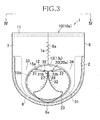
- Fig. 3 is a sectional view taken along the line III-III in Fig. 1 wherein the line III-III conforms to the longitudinal center line C-C.
- the pants-shaped skin covering assembly 10 includes the front waist region 7 and the rear waist region 8 joined together along the transversely opposite edges 7a, 8a, respectively.
- the crotch region 6 shown in Fig. 2 now bows in Fig. 3 substantially in a U-shape and the transversely opposite edges 13b of the crotch region 6 now appear as the peripheries 13 defining the respective leg-holes 12.
- the body waste receiving space 31 in the chassis 10a appears here as a pocket 20a defined by a front seal region 27 of the front waist region 21 and a rear seal region 28 of the rear end 22 of the sheet piece 20 permanently bonded together by bonding agent 32 such as hot melt adhesive or pressure-sensitive adhesive so as to form a seal region 35.
- the pocket 20a has a front opening 33 defined by the front end 21 of the sheet piece 20 corresponding to a front end of the pocket 20a together with the inner sheet 2 and a rear opening 34 defined by the rear end 22 of the sheet piece 20 corresponding to a rear end of the pocket 20a together with the inner sheet 2.
- the inner sheet 2 and the sheet piece 20 are substantially or really in contact with each other.
- Fig. 4 is an overhead view of the diaper 1 as viewed in a direction indicated by the arrow line IV-IV in Fig. 3 , i.e., as viewed from above the waist-hole 11.
- the front end 21 of the sheet piece 20 has its dimension in the transverse direction X bisected by the seal region 35 into a front end segment 21 R adapted to be held in close contact with the right leg and a front end segment 21 L adapted to be held in close contact with the left leg of the wearer (not shown).
- These front end segments 21 R , 21 L describe a V-shape in Fig. 4 .
- the rear end 22 also has its dimension in the transverse direction X bisected by the seal region 35.
- the rear end segment 22 R is adapted to be held in close contact with the right leg of the wearer and the rear end segment 22 L is adapted to be held in close contact with the left leg of the wearer wherein these rear end segments 21 R , 21 L describe a V-shape in Fig. 4 .
- the respective peripheries 13 of the leg-holes 12 in the skin covering assembly 10 comprise a periphery 13 R for the right leg and a periphery 13 L for the left leg wherein each of the peripheries 13 R , 13 L is divided into an upper segment 15a not superposed on and left free from the associated lateral edge 23 of the sheet piece 20 and a lower segment 15b joined to the associated lateral edge 23 (See Fig. 3 also).
- a range corresponding to the upper segment 15a and a range corresponding to the lower segment 15b are represented by double-headed arrows A and B, respectively.
- the front and rear waist regions 7, 8 of the skin covering assembly 10 are spaced from each other in the back-and-forth direction Y and thereby the waist-hole 11 is broadened as seen in Figs. 1 and 4 .
- the front end segment 21 R for the right leg and the front end segment 21 L for the left leg constituting the front end 21 of the sheet piece 20 are deformed about the seal region 35 so as to describe the V-shape and, in a similar way, the rear end segment 22 R for the right leg and the rear end segment 22 L for the left leg constituting the rear end 22 of the sheet piece 20 are deformed so as to described the V-shape.
- Such deformation causes the front opening 33 and the rear opening 34 of the pocket 20a to be automatically broadened (See Fig. 3 ).
- the front end segment 21 R for the right leg and the rear end segment 22 R for the right leg are widely spaced from each other while the front end segment 21 L for the left leg and the rear end segment 22 L for the left leg are widely spaced from each other.
- the right leg of the wearer (not shown) is guided through an opening 41 R for the right leg defined by the upper segment 15a of the periphery segment 13 R of the associated leg-hole 12, the front end segment 21 R for the right leg of the sheet piece 20 and the rear end segment 22 R for the right leg of the sheet piece 20.
- the right leg is guided further through the right leg-hole 12 defined by the upper segment 15a and the lower segment 15b of the periphery segment 13 R for the right leg.
- the left leg is guided through an opening 41 L for the left leg defined by the upper segment 15a of the periphery segment 13 L for the left leg, the front end segment 21 L for the left leg and the rear end segment 22 L for the left leg.
- the left leg is guided further through the left leg-hole 12 defined by the upper segment 15a and the lower segment 15b of the periphery segment 13 L for the left leg.
- the peripheries 13 of the respective leg-holes 12, i.e., the periphery 13 R for the right leg and the periphery 13 L for the left leg are elastically contractible around the respective holes 12 while the front end 21 and the rear end 22 of the sheet piece 20 are elastically contractible in the transverse direction X.
- the upper segment 15a of the periphery 13 R for the right leg, the front end segment 21 R for the right leg and the rear end segment 22 R for the right leg are elastically held in close contact around the right leg to form a primary seal 51 R (See Fig.
- the upper segment 15a of the periphery 13 L for the left leg the front end segment 21 L for the left leg and the rear end segment 22 L for the left leg are elastically held in close contact around the left leg to form a primary seal 51 L .
- the lower segment 15b and the upper segment 15a of the periphery 13 L cooperate integrally with each other to form a secondary seal 52 L .
- the pants-type diaper put on the wearer's body may be sufficiently pulled up along the waist to ensure that the front end 21 and the rear end 22 of the sheet piece 20, in the vicinity of the seal region 35, come in contact with a zone of the wearer's crotch region defined between the wearer's external genital and anus. Even after the pants-type diaper 1 has been put on the wearer's body, the front end 21 as well as the rear end 22 of the sheet piece 20 is maintained spaced from the inner sheet 2 and the front opening 33 as well as the rear opening is maintained widely broadened.
- the sheet piece 20 forming the pocket 20a distinctly divides the wearer's crotch region into a front half and a rear half so that the front opening 33 formed in the front half is reliably opposed to the wearer's external genital and the rear opening 34 is reliably opposed to the anus. Therefore, it is guaranteed that urine discharged from the external genital is guided through the front opening 33 into the pocket 20a while feces discharged from the anus is guided through the rear opening 34 into the pocket 20a. In this way, the pocket 20a or sheet piece 20 effectively prevents urine and/or feces from coming in contact with the wearer's skin.
- a possibility that urine and feces might be mixed with each other within the bodily waste receiving space 31 is effectively alleviated because the sheet piece 20 is substantially or really maintained in contact with the inner sheet 2 at the bottom 6a of the crotch region 6. Consequentially, an anxiety that a liquidity of feces might be enhanced by admixture of urine and feces is effectively alleviated by the pants-type diaper 1.
- the primary seals 51 R , 51 L and the secondary seals 52 R , 52 L provided around the wearer's legs cooperate together to prevent urine and/or feces from readily moving out beyond the leg-holes 12 of the pants-type diaper 1.
- the inner sheet 2 and the sheet piece 20 may be bonded to each other locally, for example, merely along the bottom 6a of the crotch region 6 over the full width in order to eliminate the problem that urine and feces might be mixed with each other within the pants-type diaper 1.
- stock materials for the inner sheet 2 may be selected from the group including a liquid-pervious nonwoven fabric and a perforated plastic film.
- Stock materials for the outer sheet 3 may be selected from the group including a liquid-impervious plastic film and a laminated sheet consisting of such plastic film and nonwoven fabric.
- liquid-absorbent materials for the core 4 a mixture of fluff pulp and super-absorbent polymer particles, or fluff pulp fibers alone, or a mixture of fluff pulp fibers and super-absorbent polymer fibers may be used.
- tissue paper often used may be replaced by an appropriate nonwoven fabric.
- a hydrophobic, or a hydrophobic and liquid-impervious nonwoven fabric or a plastic film may be preferably used. More preferably, the sheet materials can be elastic or inelastic so long as it is elastically or inelastically extensible in response to elastic extension of the elastic members 21b, 22b. When the sheet piece 20 is elastically contractible, the front elastic member or the rear elastic member can be omitted. If the inner and outer sheets 2, 3 and the other sheet material such as the sheet piece 20 contain any heat-fusible plastics, these sheet materials may be heat-sealed by the known sonic sealing technique.
- each distance Hf, Hr is preferably in a range of 20 to 150 mm, more preferably in a range of 40 to 80 mm.
- a dimension of the front and rear joint regions 27, 28 in the transverse direction X is preferably in a range of 3 to 50 mm, more preferably in a range of 10 to 30 mm.
- a dimension of the sheet piece 20 in the back-and-forth direction Y is at least 3 mm.
- the chassis 10a of Fig. 2 further includes a pair of side flaps 25 defined by portions of the inner and outer sheets 2, 3 extending outward in the transverse direction X beyond the transversely opposite edges of the core 4.
- the side flaps 25 have flexural stiffness in the transverse direction X lower than that of the core 4 and are correspondingly easier to be deformed.
- These side flaps 25 include the leg elastic regions 41.
- the side flaps 25 tend to raise themselves up along the lateral opposite edges 4c of the core 4 under contraction of the elastic regions 41 in the vicinity of the transverse center line D-D, i.e., at the bottom 6a of the crotch region 6.
- the sheet piece 20 is bonded along the transversely opposite edges 23 thereof to the inner surface of the elastic regions 41 by adhesive 24.
- Fig. 5 through Fig. 9 are diagrams exemplarily illustrating step of the process for continuously making the pants-type diaper 1 of Fig. 1 .
- a machine direction is indicated by an arrow MD and a cross direction orthogonal to the machine direction MD is indicated by a double-headed arrow CD.
- a first web 201 is continuously fed in the machine direction MD, preferably under tension in the machine direction MD as well as in the CD direction.
- This first web 201 is a laminate consisting of a continuous inner sheet 102 corresponding to the liquid-pervious inner sheet 2 of the chassis 10a (See Fig. 2 ) which is continuous in its transverse direction X and a continuous outer sheet 103 corresponding to the liquid-impervious outer sheet 3 which has the same width as that of the continuous inner sheet 102 and continuous in its transverse direction X.
- a plurality of body fluid absorbent cores 104 are sandwiched at regular center intervals each corresponding to the width of the chassis 10a in the machine direction MD and bonded to at least one of these continuous inner and outer sheets 102, 103 by hot melt adhesive (not shown).
- the continuous inner and outer sheets 102, 103 also are bonded to each other by hot melt adhesive (not shown).
- An imaginary line 151 extending in the cross direction CD in the middle between each pair of the adjacent cores 104 indicates a position at which the assembly including the first web 201 will be cut in a subsequent step (See Fig. 9 ) and a dimension between each pair of the adjacent imaginary lines 151, 151 is equal to the width of the chassis 10a.
- a loop-shaped imaginary line 152 illustrated in the middle region of first web 201 as viewed in the cross direction CD is illustrated to be bilaterally symmetric about the imaginary line 151 and symmetric also in the vertical direction, i.e., in the cross direction CD.
- This loop-shaped imaginary line 152 indicates a boundary surrounding a region which will be cut away in a subsequent step (See Fig. 9 ).
- leg elastic members 117a, 117b extend along the imaginary line 152 so as to be sandwiched between the continuous inner and outer sheets 102, 103 and bonded to at least one of these continuous inner and outer sheets 102, 103 by hot melt adhesive (not shown).
- These elastic members 117a, 117b respectively trace substantially semicircular courses and intersect one another so as to describe together a loop wherein these elastic members 117a, 117b are under tension at least partially along this loop.
- the first web 201 is further provided along edges 107b, 108b thereof extending in parallel to each other in the machine direction MD with elastic members 114a, 114b respectively extending under tension in the machine direction MD.
- These elastic members 114a, 114b are bonded to the inner surface of at least one of the continuous inner and outer sheets 102, 103 by hot melt adhesive (not shown).
- the opposite edges 107b, 108b of the first web 201 are nipped in thickness direction thereof by associated sets of feed rolls 153, respectively, which are paired in the cross direction and adapted to feed the first web 201 under tension in the machine direction MD.
- the sets of feed rolls 153 paired in this manner are intermittently disposed at appropriate intervals in the machine direction MD. While axes 154 of these feed rolls 153 are illustrated to extend orthogonally to the machine direction MD, an angle of these axes 154 with respect to the machine direction MD may be appropriately varied, if desired.
- tentering rolls 156 paired in the cross direction are disposed in appropriate regions along the opposite edges 107b, 108b so that these tentering rolls 156 may be held in contact with the continuous inner sheet 102 and thereby tenter the first web 201 in the cross direction CD. While axes 157 of the respective tentering rolls 156 are illustrated to intersect with the machine direction MD obliquely at a particular angle, this angle is not limited to the particular angle as illustrated.
- An imaginary line p-p in Fig. 5 indicates a first center line bisecting the first web 201 in the cross direction CD. It will be appreciated that the first web 201 may be fed in the machine direction MD by any means replacing the rolls 153, 156 used in the illustrated embodiment. In the illustrated embodiment, the first web 201 may be successively cut at a pitch corresponding to a distance between each pair of the adjacent imaginary lines 151, 151 to obtain the chassis 10a in a continuous fashion.
- a second web 202 comprising the sheet pieces 20 destined to be attached to the associated chassis 10a and continuously arranged in the transverse direction X is continuously fed in the machine direction MD preferably under tension in the machine direction MD as well as in the cross direction CD.
- feed rolls 158 and tentering rolls 159 are used.
- the second web 202 has a pair of edges 121c, 122c extending in parallel to each other in the machine direction MD and the one edge 122c of these edges 121c, 122c is coated at regular pitches each corresponding to the width of the chassis 10a, i.e., corresponding to the distance between each pair of the adjacent imaginary lines 151, 151 as illustrated in Fig. 5 with bonding agent 132 such as pressure-sensitive adhesive.
- An imaginary line q-q indicated in Fig. 6 defines a second center line bisecting the second web into two dimensions Hf, Hr in the cross direction CD.
- a third step III illustrated by Fig. 7 the second web 202 is folded back onto itself along a folding guide line defined by the second center line q-q with the bonding agent 132 inside and thereby the respective halves of the second web 202 folded back in this manner are locally bonded to each other by the bonding agent 132 to obtain a third web 203 having a seal region 135.
- the third web 203 also can be fed in the machine direction MD using the feed rolls 158 and the tentering rolls 159.
- a fourth step IV illustrated by Fig. 8 the first web 201 corresponding to the continuous inner sheet 102 is coated immediately outside and along the loop-shaped imaginary line 152 with hot melt adhesive 124.
- the range over which the continuous inner sheet 102 is coated with the adhesive 124 extends on both sides from the first center line p-p in the cross direction CD by a distance m, preferably so that this range extends sufficiently to cover the elastic members 117a, 117b.
- a fifth step V illustrated by Fig. 8 the third web 203 is superposed upon the continuous inner sheet 102 in the first web 201 so that the second center line q-q is co-aligned with the first center line p-p and the seal region 135 is located in the middle between the adjacent imaginary lines 151, 151, in other words, located in the middle of the chassis 10a as viewed in the transverse direction thereof.
- the first web 201 and the third web 203 are bonded together by the adhesive 124 coated on the first web 201 and thereby a first composite web 301 is obtained.
- the first composite web 301 the first web 201 and the third web 203 are free from each other in the remaining region with respect to the region occupied by the adhesive 124.
- the third web 203 may be bonded to the first web 201 in the vicinity of the middle between each pair of the adjacent imaginary lines 151, 151.
- the elastic members 114a, 114b, 117a, 117b, 121b, 122b are indicated by chained lines as if seen through but the adhesive 124 is not indicated. It should be understood that the first center line p-p and the second center line q-q to are co-aligned with each other in the fifth step V may be misaligned with each other so far as such alignment does not disturb making and use of the pants-type diaper.
- the first composite web 301 is folded back onto itself along a folding guide line defined by the first center line p-p of the first web 201 with the third web 203 inside wherein the first web 201 and the third web 203 superposed upon each other are bonded together by the adhesive 124 (See Fig. 8 ) to obtain a second composite web 302.
- the first web 201 and the third web 203 may be compressed in thickness direction thereof to assure desired bonding effect.
- the loop-shaped imaginary line 152 described on the first web 201 to be symmetric about the first center line p-p now describes on the second composite web 302 a circular arc which is convex from a chord defined by the first center line p-p toward the edges 107b, 108b (See Fig. 5 ) co-aligned with each other so as to describe a substantially semicircular shape which is bilaterally symmetric as viewed in the machine direction.
- the region in which the first web 201 and the third web 203 are bonded to each other by the adhesive 124 in the sixth step VI is superposed on the region in which the first web 201 and the third web 203 are bonded to each other by the adhesive 124 in the fifth step V.
- the first web 201 and the third web 203 are free from each other in the remaining region with respect to the region occupied by the adhesive 124.
- the section surrounded by the substantially circular imaginary line 152 is clipped out from the second composite web 302 to obtain the third composite web 303 having a substantially semicircular notch 112.
- This clipping step generates scrap in the form of substantially semicircular web pieces 215 clipped out from the second composite web 302.
- Each notch 112 is substantially semicircular shaped and symmetric about the imaginary line 151.
- the inner surface of the first web 201 folded in two is bonded to itself on both sides of the imaginary line 151 along two seal regions each comprising a plurality of seal stripes 109a, 109b to obtain a fourth composite web 304.
- appropriate bonding means such as sonic sealing technique or hot melt adhesive may be used.
- a plurality of seal stripes 109a and a plurality of seal stripes 109b form linear seal regions 109, respectively, which are belt-like regions extending in the cross direction CD.
- the fourth web 304 is cut along the imaginary line 151 bisecting the seal region 109 in the machine direction MD to obtain the individual pants-type diaper 1.
- the chassis 10a and the sheet piece 20 in the pants-type diaper 1 shown in Fig. 1 is obtained from the first web 201 and the second web 202, respectively, used in the steps illustrated by Figs. 5 through 9 .
- the inner sheet 2, the outer sheet 3 and the liquid-absorbent core 4 are obtained from the continuous inner sheet 102, the continuous outer sheet 103 and the liquid-absorbent core 104, respectively.
- the periphery of the circular notch 112 is destined to form the peripheries 13 of the leg-holes 12 in the diaper 1 and the elastic members 117a, 117b are respectively divided in right and left halves along the imaginary line 151 to form the front elastic members 17a and the rear elastic members 17b of the respective leg elastic members 17 shown in Fig. 2 .
- the elastic members 114a, 114b in the first web 201 correspond to the waist elastic members 14a, 14b in Fig. 1 , respectively.
- the method for making the pants-type diaper exemplarily illustrated allows the first web 201, the second web 202, the third web 203 and the like to be maintained under tension in the machine direction MD as well as in the cross direction CD by the feed rolls and the tentering rolls disposed at appropriate locations along the edges of these webs, respectively. There is no need for chucks or the like used only for the purpose of keeping these first and second webs 201, 202 under tension and therefore both the first web 201 and the second web 202 are not wasted in the course of making the pants-type diaper 1.
- the pants-type diaper 1 made by the method of the invention advantageously facilitates the external genitals and the anus of the wearer to be exactly opposed to the front opening 33 and the rear opening 34, respectively, of the pocket 20a in the diaper 1 (See Figs. 1 , 3 and 4 ).
- the second web 202 destined to form the pocket 20a is folded in two so as to obtain the third web 203 carrying the seal region 135 before the third web 203 is bonded to the first web 201. In this way, formation of the seal region 35 in the pants-type diaper 1 would not be accompanied with any significant difficulty.
- the present invention is not limited to the steps exemplarily illustrated but contents of the respective steps as well as the order of these steps may be variously modified without departing from the object of the present invention.
- the first web 201 may be previously coated with the adhesive 124 along the segment of the loop-shaped imaginary line 152 extending above the first center line p-p and then the third web 203 may be bonded to the first web 201. Thereafter, the first web 201 may be coated with the adhesive 124 along the segment of the loop-shaped imaginary line 152 extending below the first center line p-p and then the first web 201 may be folded back along the first center line p-p so that the first web 201 and the third web 203 thus superposed on each other may be bonded to each other.
- the step modified in this manner even when the first web 201 and the third web 203 are bonded to each other under a compression, the presence of the adhesive 124 coated on the first web 201 would not pose an impediment on the operation of compression.
- the step VII and the step VIII may be order-reversed in the method exemplarily illustrated so that the notch 112 may be formed after the second composite web 302 has been formed with the seal region 109.
- the second web 202 is formed by a nonwoven fabric made of thermoplastic synthetic fibers, the respective halves of the second web 202 may be bonded together by sonic sealing technique instead of the bonding agent 132.
Landscapes
- Health & Medical Sciences (AREA)
- Engineering & Computer Science (AREA)
- Life Sciences & Earth Sciences (AREA)
- Biomedical Technology (AREA)
- Heart & Thoracic Surgery (AREA)
- Vascular Medicine (AREA)
- Epidemiology (AREA)
- Animal Behavior & Ethology (AREA)
- General Health & Medical Sciences (AREA)
- Public Health (AREA)
- Veterinary Medicine (AREA)
- Manufacturing & Machinery (AREA)
- Mechanical Engineering (AREA)
- Absorbent Articles And Supports Therefor (AREA)
- Orthopedics, Nursing, And Contraception (AREA)
Applications Claiming Priority (2)
| Application Number | Priority Date | Filing Date | Title |
|---|---|---|---|
| JP2007005151A JP5074774B2 (ja) | 2007-01-12 | 2007-01-12 | 使い捨てのパンツ型おむつの製造方法 |
| PCT/JP2007/072303 WO2008084596A1 (ja) | 2007-01-12 | 2007-11-16 | 使い捨てのパンツ型おむつの製造方法 |
Publications (3)
| Publication Number | Publication Date |
|---|---|
| EP2106772A1 true EP2106772A1 (de) | 2009-10-07 |
| EP2106772A4 EP2106772A4 (de) | 2012-06-27 |
| EP2106772B1 EP2106772B1 (de) | 2013-02-27 |
Family
ID=39608494
Family Applications (1)
| Application Number | Title | Priority Date | Filing Date |
|---|---|---|---|
| EP07832033A Not-in-force EP2106772B1 (de) | 2007-01-12 | 2007-11-16 | Verfahren zur herstellung von einweg-windeln vom höschentyp |
Country Status (16)
| Country | Link |
|---|---|
| US (1) | US8114236B2 (de) |
| EP (1) | EP2106772B1 (de) |
| JP (1) | JP5074774B2 (de) |
| KR (1) | KR20090104096A (de) |
| CN (1) | CN101578082B (de) |
| AU (1) | AU2007342937B2 (de) |
| BR (1) | BRPI0720321A2 (de) |
| CA (1) | CA2675287A1 (de) |
| EA (1) | EA016754B1 (de) |
| EG (1) | EG25694A (de) |
| MA (1) | MA31173B1 (de) |
| MX (1) | MX2009007468A (de) |
| MY (1) | MY148189A (de) |
| TW (1) | TWI391130B (de) |
| UA (1) | UA93612C2 (de) |
| WO (1) | WO2008084596A1 (de) |
Families Citing this family (5)
| Publication number | Priority date | Publication date | Assignee | Title |
|---|---|---|---|---|
| JP5054982B2 (ja) * | 2007-01-12 | 2012-10-24 | ユニ・チャーム株式会社 | 使い捨てのパンツ型おむつの製造方法 |
| US8663415B2 (en) * | 2009-11-24 | 2014-03-04 | Kimberly-Clark Worldwide, Inc. | Method of making disposable pants having underwear-like waistbands, and pant made thereby |
| JP5360327B1 (ja) * | 2013-06-03 | 2013-12-04 | 王子ホールディングス株式会社 | パンツ型使い捨ておむつ及びその製造方法 |
| US10342710B2 (en) * | 2014-11-14 | 2019-07-09 | Zuiko Corporation | Method and device for manufacturing worn article |
| JP6751625B2 (ja) * | 2016-08-29 | 2020-09-09 | ユニ・チャーム株式会社 | パンツ型吸収性物品 |
Citations (4)
| Publication number | Priority date | Publication date | Assignee | Title |
|---|---|---|---|---|
| EP1084688A2 (de) * | 1999-09-16 | 2001-03-21 | Uni-Charm Corporation | Wegwerfwindel |
| US6409711B1 (en) * | 1997-05-26 | 2002-06-25 | Sca Hygiene Products Ab | Barrier for an absorbent product |
| EP1297809A1 (de) * | 2000-06-29 | 2003-04-02 | Oji Paper Co., Ltd. | Absorbierendes produkt |
| EP2011461A1 (de) * | 2006-04-06 | 2009-01-07 | Unicharm Corporation | Einwegwindel vom höschentyp |
Family Cites Families (12)
| Publication number | Priority date | Publication date | Assignee | Title |
|---|---|---|---|---|
| JPS60114258A (ja) * | 1983-11-24 | 1985-06-20 | 大崎衛生材料株式会社 | 紙おむつ |
| JP3107862B2 (ja) | 1991-08-15 | 2000-11-13 | ユニ・チャーム株式会社 | 使い捨てパンツの製造方法 |
| JP2757931B2 (ja) * | 1993-05-26 | 1998-05-25 | 株式会社日本吸収体技術研究所 | テープレス形吸収体製品およびその製造方法 |
| SE502548C2 (sv) | 1994-03-18 | 1995-11-13 | Moelnlycke Ab | Absorberande artikel, såsom en blöja, innefattande sidobarriärer i form av längsgående flikar förbundna med ett inre vätskegenomsläppligt höljeskikt |
| US6077254A (en) * | 1994-07-12 | 2000-06-20 | Paragon Trade Brands, Inc. | Absorbent garment with containment pocket |
| US5711832A (en) * | 1995-05-31 | 1998-01-27 | Kimberly-Clark Worldwide, Inc. | Process for making a training pant having a separate waist elastic system |
| US6432248B1 (en) * | 2000-05-16 | 2002-08-13 | Kimberly-Clark Worldwide, Inc. | Process for making a garment with refastenable sides and butt seams |
| JP4480859B2 (ja) | 2000-06-29 | 2010-06-16 | 王子製紙株式会社 | おむつ |
| AU2001288074A1 (en) * | 2000-09-21 | 2002-04-02 | Japan Absorbent Technology Institute | Absorptive product having removable absorbers |
| JP3862510B2 (ja) * | 2001-03-15 | 2006-12-27 | ユニ・チャーム株式会社 | パンツ型おむつの連続的製造方法 |
| US9114041B2 (en) * | 2004-09-29 | 2015-08-25 | Sca Hygiene Products Ab | Method for production of disposable absorbent articles |
| JP5054982B2 (ja) * | 2007-01-12 | 2012-10-24 | ユニ・チャーム株式会社 | 使い捨てのパンツ型おむつの製造方法 |
-
2007
- 2007-01-12 JP JP2007005151A patent/JP5074774B2/ja not_active Expired - Fee Related
- 2007-11-16 EP EP07832033A patent/EP2106772B1/de not_active Not-in-force
- 2007-11-16 AU AU2007342937A patent/AU2007342937B2/en not_active Ceased
- 2007-11-16 MX MX2009007468A patent/MX2009007468A/es active IP Right Grant
- 2007-11-16 CA CA002675287A patent/CA2675287A1/en not_active Abandoned
- 2007-11-16 WO PCT/JP2007/072303 patent/WO2008084596A1/ja active Application Filing
- 2007-11-16 EA EA200900869A patent/EA016754B1/ru not_active IP Right Cessation
- 2007-11-16 MY MYPI20092879A patent/MY148189A/en unknown
- 2007-11-16 CN CN2007800497440A patent/CN101578082B/zh not_active Expired - Fee Related
- 2007-11-16 UA UAA200908373A patent/UA93612C2/ru unknown
- 2007-11-16 KR KR1020097016645A patent/KR20090104096A/ko active IP Right Grant
- 2007-11-16 US US12/522,588 patent/US8114236B2/en not_active Expired - Fee Related
- 2007-11-16 BR BRPI0720321-7A2A patent/BRPI0720321A2/pt not_active IP Right Cessation
-
2008
- 2008-01-07 TW TW097100570A patent/TWI391130B/zh active
-
2009
- 2009-07-12 EG EG2009071070A patent/EG25694A/xx active
- 2009-08-06 MA MA32152A patent/MA31173B1/fr unknown
Patent Citations (4)
| Publication number | Priority date | Publication date | Assignee | Title |
|---|---|---|---|---|
| US6409711B1 (en) * | 1997-05-26 | 2002-06-25 | Sca Hygiene Products Ab | Barrier for an absorbent product |
| EP1084688A2 (de) * | 1999-09-16 | 2001-03-21 | Uni-Charm Corporation | Wegwerfwindel |
| EP1297809A1 (de) * | 2000-06-29 | 2003-04-02 | Oji Paper Co., Ltd. | Absorbierendes produkt |
| EP2011461A1 (de) * | 2006-04-06 | 2009-01-07 | Unicharm Corporation | Einwegwindel vom höschentyp |
Non-Patent Citations (1)
| Title |
|---|
| See also references of WO2008084596A1 * |
Also Published As
| Publication number | Publication date |
|---|---|
| EG25694A (en) | 2012-05-21 |
| MA31173B1 (fr) | 2010-02-01 |
| AU2007342937A1 (en) | 2008-07-17 |
| CN101578082A (zh) | 2009-11-11 |
| BRPI0720321A2 (pt) | 2013-12-24 |
| UA93612C2 (ru) | 2011-02-25 |
| JP2008168012A (ja) | 2008-07-24 |
| TW200847999A (en) | 2008-12-16 |
| US20100038018A1 (en) | 2010-02-18 |
| AU2007342937B2 (en) | 2013-08-01 |
| WO2008084596A1 (ja) | 2008-07-17 |
| KR20090104096A (ko) | 2009-10-05 |
| CN101578082B (zh) | 2013-02-13 |
| EP2106772B1 (de) | 2013-02-27 |
| CA2675287A1 (en) | 2008-07-17 |
| EA200900869A1 (ru) | 2010-02-26 |
| MY148189A (en) | 2013-03-15 |
| TWI391130B (zh) | 2013-04-01 |
| US8114236B2 (en) | 2012-02-14 |
| JP5074774B2 (ja) | 2012-11-14 |
| EP2106772A4 (de) | 2012-06-27 |
| EA016754B1 (ru) | 2012-07-30 |
| MX2009007468A (es) | 2009-07-22 |
Similar Documents
| Publication | Publication Date | Title |
|---|---|---|
| CA2717334C (en) | Absorbent article | |
| US8777918B2 (en) | Disposable absorbent wearing article | |
| AU2002253560B2 (en) | Underpants-type disposable wearing article | |
| US7722734B2 (en) | Method for making disposable pants-type diaper | |
| EP1854440A1 (de) | Tragbarer einwegartikel | |
| AU2007320642B2 (en) | Method for making disposable pants-type diaper and pants-type diaper obtained by this method | |
| EP2301500B1 (de) | Herstellungsverfahren für ein kleidungsstück | |
| EP2106772B1 (de) | Verfahren zur herstellung von einweg-windeln vom höschentyp | |
| US20030023224A1 (en) | Pants-type disposable diaper | |
| EP2241300A1 (de) | Einwegwindel vom höschentyp | |
| US7901391B2 (en) | Disposable pants type wearing article | |
| EP2106771B1 (de) | Verfahren zur herstellung von einweg-windeln vom höschentyp | |
| US8460264B2 (en) | Wearing article and method for making the same | |
| EP2221032B1 (de) | Tragbarer artikel |
Legal Events
| Date | Code | Title | Description |
|---|---|---|---|
| PUAI | Public reference made under article 153(3) epc to a published international application that has entered the european phase |
Free format text: ORIGINAL CODE: 0009012 |
|
| 17P | Request for examination filed |
Effective date: 20090807 |
|
| AK | Designated contracting states |
Kind code of ref document: A1 Designated state(s): AT BE BG CH CY CZ DE DK EE ES FI FR GB GR HU IE IS IT LI LT LU LV MC MT NL PL PT RO SE SI SK TR |
|
| DAX | Request for extension of the european patent (deleted) | ||
| A4 | Supplementary search report drawn up and despatched |
Effective date: 20120531 |
|
| RIC1 | Information provided on ipc code assigned before grant |
Ipc: A61F 13/15 20060101AFI20120524BHEP Ipc: A61F 13/495 20060101ALI20120524BHEP Ipc: A61F 13/49 20060101ALI20120524BHEP Ipc: A61F 13/496 20060101ALI20120524BHEP |
|
| GRAP | Despatch of communication of intention to grant a patent |
Free format text: ORIGINAL CODE: EPIDOSNIGR1 |
|
| GRAS | Grant fee paid |
Free format text: ORIGINAL CODE: EPIDOSNIGR3 |
|
| GRAA | (expected) grant |
Free format text: ORIGINAL CODE: 0009210 |
|
| AK | Designated contracting states |
Kind code of ref document: B1 Designated state(s): AT BE BG CH CY CZ DE DK EE ES FI FR GB GR HU IE IS IT LI LT LU LV MC MT NL PL PT RO SE SI SK TR |
|
| REG | Reference to a national code |
Ref country code: GB Ref legal event code: FG4D |
|
| REG | Reference to a national code |
Ref country code: CH Ref legal event code: EP |
|
| REG | Reference to a national code |
Ref country code: AT Ref legal event code: REF Ref document number: 598100 Country of ref document: AT Kind code of ref document: T Effective date: 20130315 |
|
| REG | Reference to a national code |
Ref country code: IE Ref legal event code: FG4D |
|
| REG | Reference to a national code |
Ref country code: DE Ref legal event code: R096 Ref document number: 602007028789 Country of ref document: DE Effective date: 20130425 |
|
| REG | Reference to a national code |
Ref country code: SE Ref legal event code: TRGR |
|
| REG | Reference to a national code |
Ref country code: NL Ref legal event code: T3 |
|
| REG | Reference to a national code |
Ref country code: AT Ref legal event code: MK05 Ref document number: 598100 Country of ref document: AT Kind code of ref document: T Effective date: 20130227 |
|
| REG | Reference to a national code |
Ref country code: LT Ref legal event code: MG4D |
|
| PG25 | Lapsed in a contracting state [announced via postgrant information from national office to epo] |
Ref country code: BG Free format text: LAPSE BECAUSE OF FAILURE TO SUBMIT A TRANSLATION OF THE DESCRIPTION OR TO PAY THE FEE WITHIN THE PRESCRIBED TIME-LIMIT Effective date: 20130527 Ref country code: LT Free format text: LAPSE BECAUSE OF FAILURE TO SUBMIT A TRANSLATION OF THE DESCRIPTION OR TO PAY THE FEE WITHIN THE PRESCRIBED TIME-LIMIT Effective date: 20130227 Ref country code: AT Free format text: LAPSE BECAUSE OF FAILURE TO SUBMIT A TRANSLATION OF THE DESCRIPTION OR TO PAY THE FEE WITHIN THE PRESCRIBED TIME-LIMIT Effective date: 20130227 Ref country code: IS Free format text: LAPSE BECAUSE OF FAILURE TO SUBMIT A TRANSLATION OF THE DESCRIPTION OR TO PAY THE FEE WITHIN THE PRESCRIBED TIME-LIMIT Effective date: 20130627 Ref country code: ES Free format text: LAPSE BECAUSE OF FAILURE TO SUBMIT A TRANSLATION OF THE DESCRIPTION OR TO PAY THE FEE WITHIN THE PRESCRIBED TIME-LIMIT Effective date: 20130607 |
|
| PG25 | Lapsed in a contracting state [announced via postgrant information from national office to epo] |
Ref country code: LV Free format text: LAPSE BECAUSE OF FAILURE TO SUBMIT A TRANSLATION OF THE DESCRIPTION OR TO PAY THE FEE WITHIN THE PRESCRIBED TIME-LIMIT Effective date: 20130227 Ref country code: FI Free format text: LAPSE BECAUSE OF FAILURE TO SUBMIT A TRANSLATION OF THE DESCRIPTION OR TO PAY THE FEE WITHIN THE PRESCRIBED TIME-LIMIT Effective date: 20130227 Ref country code: PT Free format text: LAPSE BECAUSE OF FAILURE TO SUBMIT A TRANSLATION OF THE DESCRIPTION OR TO PAY THE FEE WITHIN THE PRESCRIBED TIME-LIMIT Effective date: 20130627 Ref country code: SI Free format text: LAPSE BECAUSE OF FAILURE TO SUBMIT A TRANSLATION OF THE DESCRIPTION OR TO PAY THE FEE WITHIN THE PRESCRIBED TIME-LIMIT Effective date: 20130227 Ref country code: GR Free format text: LAPSE BECAUSE OF FAILURE TO SUBMIT A TRANSLATION OF THE DESCRIPTION OR TO PAY THE FEE WITHIN THE PRESCRIBED TIME-LIMIT Effective date: 20130528 Ref country code: BE Free format text: LAPSE BECAUSE OF FAILURE TO SUBMIT A TRANSLATION OF THE DESCRIPTION OR TO PAY THE FEE WITHIN THE PRESCRIBED TIME-LIMIT Effective date: 20130227 Ref country code: PL Free format text: LAPSE BECAUSE OF FAILURE TO SUBMIT A TRANSLATION OF THE DESCRIPTION OR TO PAY THE FEE WITHIN THE PRESCRIBED TIME-LIMIT Effective date: 20130227 |
|
| PG25 | Lapsed in a contracting state [announced via postgrant information from national office to epo] |
Ref country code: CZ Free format text: LAPSE BECAUSE OF FAILURE TO SUBMIT A TRANSLATION OF THE DESCRIPTION OR TO PAY THE FEE WITHIN THE PRESCRIBED TIME-LIMIT Effective date: 20130227 Ref country code: DK Free format text: LAPSE BECAUSE OF FAILURE TO SUBMIT A TRANSLATION OF THE DESCRIPTION OR TO PAY THE FEE WITHIN THE PRESCRIBED TIME-LIMIT Effective date: 20130227 Ref country code: SK Free format text: LAPSE BECAUSE OF FAILURE TO SUBMIT A TRANSLATION OF THE DESCRIPTION OR TO PAY THE FEE WITHIN THE PRESCRIBED TIME-LIMIT Effective date: 20130227 Ref country code: EE Free format text: LAPSE BECAUSE OF FAILURE TO SUBMIT A TRANSLATION OF THE DESCRIPTION OR TO PAY THE FEE WITHIN THE PRESCRIBED TIME-LIMIT Effective date: 20130227 Ref country code: RO Free format text: LAPSE BECAUSE OF FAILURE TO SUBMIT A TRANSLATION OF THE DESCRIPTION OR TO PAY THE FEE WITHIN THE PRESCRIBED TIME-LIMIT Effective date: 20130227 |
|
| PG25 | Lapsed in a contracting state [announced via postgrant information from national office to epo] |
Ref country code: CY Free format text: LAPSE BECAUSE OF FAILURE TO SUBMIT A TRANSLATION OF THE DESCRIPTION OR TO PAY THE FEE WITHIN THE PRESCRIBED TIME-LIMIT Effective date: 20130227 |
|
| PG25 | Lapsed in a contracting state [announced via postgrant information from national office to epo] |
Ref country code: IT Free format text: LAPSE BECAUSE OF FAILURE TO SUBMIT A TRANSLATION OF THE DESCRIPTION OR TO PAY THE FEE WITHIN THE PRESCRIBED TIME-LIMIT Effective date: 20130227 |
|
| PLBE | No opposition filed within time limit |
Free format text: ORIGINAL CODE: 0009261 |
|
| STAA | Information on the status of an ep patent application or granted ep patent |
Free format text: STATUS: NO OPPOSITION FILED WITHIN TIME LIMIT |
|
| 26N | No opposition filed |
Effective date: 20131128 |
|
| REG | Reference to a national code |
Ref country code: DE Ref legal event code: R097 Ref document number: 602007028789 Country of ref document: DE Effective date: 20131128 |
|
| REG | Reference to a national code |
Ref country code: CH Ref legal event code: PL |
|
| PG25 | Lapsed in a contracting state [announced via postgrant information from national office to epo] |
Ref country code: MC Free format text: LAPSE BECAUSE OF FAILURE TO SUBMIT A TRANSLATION OF THE DESCRIPTION OR TO PAY THE FEE WITHIN THE PRESCRIBED TIME-LIMIT Effective date: 20130227 Ref country code: CH Free format text: LAPSE BECAUSE OF NON-PAYMENT OF DUE FEES Effective date: 20131130 Ref country code: LI Free format text: LAPSE BECAUSE OF NON-PAYMENT OF DUE FEES Effective date: 20131130 |
|
| REG | Reference to a national code |
Ref country code: IE Ref legal event code: MM4A |
|
| PG25 | Lapsed in a contracting state [announced via postgrant information from national office to epo] |
Ref country code: IE Free format text: LAPSE BECAUSE OF NON-PAYMENT OF DUE FEES Effective date: 20131116 |
|
| PG25 | Lapsed in a contracting state [announced via postgrant information from national office to epo] |
Ref country code: TR Free format text: LAPSE BECAUSE OF FAILURE TO SUBMIT A TRANSLATION OF THE DESCRIPTION OR TO PAY THE FEE WITHIN THE PRESCRIBED TIME-LIMIT Effective date: 20130227 |
|
| PG25 | Lapsed in a contracting state [announced via postgrant information from national office to epo] |
Ref country code: LU Free format text: LAPSE BECAUSE OF NON-PAYMENT OF DUE FEES Effective date: 20131116 Ref country code: HU Free format text: LAPSE BECAUSE OF FAILURE TO SUBMIT A TRANSLATION OF THE DESCRIPTION OR TO PAY THE FEE WITHIN THE PRESCRIBED TIME-LIMIT; INVALID AB INITIO Effective date: 20071116 |
|
| PG25 | Lapsed in a contracting state [announced via postgrant information from national office to epo] |
Ref country code: MT Free format text: LAPSE BECAUSE OF FAILURE TO SUBMIT A TRANSLATION OF THE DESCRIPTION OR TO PAY THE FEE WITHIN THE PRESCRIBED TIME-LIMIT Effective date: 20130227 |
|
| REG | Reference to a national code |
Ref country code: FR Ref legal event code: PLFP Year of fee payment: 9 |
|
| REG | Reference to a national code |
Ref country code: FR Ref legal event code: PLFP Year of fee payment: 10 |
|
| PGFP | Annual fee paid to national office [announced via postgrant information from national office to epo] |
Ref country code: FR Payment date: 20161014 Year of fee payment: 10 Ref country code: GB Payment date: 20161116 Year of fee payment: 10 Ref country code: DE Payment date: 20161108 Year of fee payment: 10 Ref country code: NL Payment date: 20161010 Year of fee payment: 10 |
|
| PGFP | Annual fee paid to national office [announced via postgrant information from national office to epo] |
Ref country code: SE Payment date: 20161111 Year of fee payment: 10 |
|
| REG | Reference to a national code |
Ref country code: DE Ref legal event code: R119 Ref document number: 602007028789 Country of ref document: DE |
|
| REG | Reference to a national code |
Ref country code: SE Ref legal event code: EUG |
|
| REG | Reference to a national code |
Ref country code: NL Ref legal event code: MM Effective date: 20171201 |
|
| GBPC | Gb: european patent ceased through non-payment of renewal fee |
Effective date: 20171116 |
|
| PG25 | Lapsed in a contracting state [announced via postgrant information from national office to epo] |
Ref country code: SE Free format text: LAPSE BECAUSE OF NON-PAYMENT OF DUE FEES Effective date: 20171117 |
|
| REG | Reference to a national code |
Ref country code: FR Ref legal event code: ST Effective date: 20180731 |
|
| PG25 | Lapsed in a contracting state [announced via postgrant information from national office to epo] |
Ref country code: FR Free format text: LAPSE BECAUSE OF NON-PAYMENT OF DUE FEES Effective date: 20171130 Ref country code: DE Free format text: LAPSE BECAUSE OF NON-PAYMENT OF DUE FEES Effective date: 20180602 Ref country code: NL Free format text: LAPSE BECAUSE OF NON-PAYMENT OF DUE FEES Effective date: 20171201 |
|
| PG25 | Lapsed in a contracting state [announced via postgrant information from national office to epo] |
Ref country code: GB Free format text: LAPSE BECAUSE OF NON-PAYMENT OF DUE FEES Effective date: 20171116 |
|
| REG | Reference to a national code |
Ref country code: IE Ref legal event code: NE4A |