EP2105579A2 - An article formed from a composite material - Google Patents
An article formed from a composite material Download PDFInfo
- Publication number
- EP2105579A2 EP2105579A2 EP20090250356 EP09250356A EP2105579A2 EP 2105579 A2 EP2105579 A2 EP 2105579A2 EP 20090250356 EP20090250356 EP 20090250356 EP 09250356 A EP09250356 A EP 09250356A EP 2105579 A2 EP2105579 A2 EP 2105579A2
- Authority
- EP
- European Patent Office
- Prior art keywords
- article
- core
- rods
- fibres
- reinforcement
- Prior art date
- Legal status (The legal status is an assumption and is not a legal conclusion. Google has not performed a legal analysis and makes no representation as to the accuracy of the status listed.)
- Granted
Links
Images

Classifications
-
- F—MECHANICAL ENGINEERING; LIGHTING; HEATING; WEAPONS; BLASTING
- F01—MACHINES OR ENGINES IN GENERAL; ENGINE PLANTS IN GENERAL; STEAM ENGINES
- F01D—NON-POSITIVE DISPLACEMENT MACHINES OR ENGINES, e.g. STEAM TURBINES
- F01D5/00—Blades; Blade-carrying members; Heating, heat-insulating, cooling or antivibration means on the blades or the members
- F01D5/12—Blades
- F01D5/14—Form or construction
- F01D5/147—Construction, i.e. structural features, e.g. of weight-saving hollow blades
-
- B—PERFORMING OPERATIONS; TRANSPORTING
- B29—WORKING OF PLASTICS; WORKING OF SUBSTANCES IN A PLASTIC STATE IN GENERAL
- B29C—SHAPING OR JOINING OF PLASTICS; SHAPING OF MATERIAL IN A PLASTIC STATE, NOT OTHERWISE PROVIDED FOR; AFTER-TREATMENT OF THE SHAPED PRODUCTS, e.g. REPAIRING
- B29C70/00—Shaping composites, i.e. plastics material comprising reinforcements, fillers or preformed parts, e.g. inserts
- B29C70/04—Shaping composites, i.e. plastics material comprising reinforcements, fillers or preformed parts, e.g. inserts comprising reinforcements only, e.g. self-reinforcing plastics
- B29C70/06—Fibrous reinforcements only
- B29C70/08—Fibrous reinforcements only comprising combinations of different forms of fibrous reinforcements incorporated in matrix material, forming one or more layers, and with or without non-reinforced layers
-
- B—PERFORMING OPERATIONS; TRANSPORTING
- B29—WORKING OF PLASTICS; WORKING OF SUBSTANCES IN A PLASTIC STATE IN GENERAL
- B29C—SHAPING OR JOINING OF PLASTICS; SHAPING OF MATERIAL IN A PLASTIC STATE, NOT OTHERWISE PROVIDED FOR; AFTER-TREATMENT OF THE SHAPED PRODUCTS, e.g. REPAIRING
- B29C70/00—Shaping composites, i.e. plastics material comprising reinforcements, fillers or preformed parts, e.g. inserts
- B29C70/04—Shaping composites, i.e. plastics material comprising reinforcements, fillers or preformed parts, e.g. inserts comprising reinforcements only, e.g. self-reinforcing plastics
- B29C70/26—Non-fibrous reinforcements only
-
- B—PERFORMING OPERATIONS; TRANSPORTING
- B29—WORKING OF PLASTICS; WORKING OF SUBSTANCES IN A PLASTIC STATE IN GENERAL
- B29C—SHAPING OR JOINING OF PLASTICS; SHAPING OF MATERIAL IN A PLASTIC STATE, NOT OTHERWISE PROVIDED FOR; AFTER-TREATMENT OF THE SHAPED PRODUCTS, e.g. REPAIRING
- B29C70/00—Shaping composites, i.e. plastics material comprising reinforcements, fillers or preformed parts, e.g. inserts
- B29C70/68—Shaping composites, i.e. plastics material comprising reinforcements, fillers or preformed parts, e.g. inserts by incorporating or moulding on preformed parts, e.g. inserts or layers, e.g. foam blocks
- B29C70/681—Component parts, details or accessories; Auxiliary operations
- B29C70/682—Preformed parts characterised by their structure, e.g. form
-
- B—PERFORMING OPERATIONS; TRANSPORTING
- B29—WORKING OF PLASTICS; WORKING OF SUBSTANCES IN A PLASTIC STATE IN GENERAL
- B29C—SHAPING OR JOINING OF PLASTICS; SHAPING OF MATERIAL IN A PLASTIC STATE, NOT OTHERWISE PROVIDED FOR; AFTER-TREATMENT OF THE SHAPED PRODUCTS, e.g. REPAIRING
- B29C70/00—Shaping composites, i.e. plastics material comprising reinforcements, fillers or preformed parts, e.g. inserts
- B29C70/68—Shaping composites, i.e. plastics material comprising reinforcements, fillers or preformed parts, e.g. inserts by incorporating or moulding on preformed parts, e.g. inserts or layers, e.g. foam blocks
- B29C70/681—Component parts, details or accessories; Auxiliary operations
- B29C70/683—Pretreatment of the preformed part, e.g. insert
-
- F—MECHANICAL ENGINEERING; LIGHTING; HEATING; WEAPONS; BLASTING
- F01—MACHINES OR ENGINES IN GENERAL; ENGINE PLANTS IN GENERAL; STEAM ENGINES
- F01D—NON-POSITIVE DISPLACEMENT MACHINES OR ENGINES, e.g. STEAM TURBINES
- F01D5/00—Blades; Blade-carrying members; Heating, heat-insulating, cooling or antivibration means on the blades or the members
- F01D5/12—Blades
- F01D5/28—Selecting particular materials; Particular measures relating thereto; Measures against erosion or corrosion
- F01D5/282—Selecting composite materials, e.g. blades with reinforcing filaments
-
- F—MECHANICAL ENGINEERING; LIGHTING; HEATING; WEAPONS; BLASTING
- F05—INDEXING SCHEMES RELATING TO ENGINES OR PUMPS IN VARIOUS SUBCLASSES OF CLASSES F01-F04
- F05D—INDEXING SCHEME FOR ASPECTS RELATING TO NON-POSITIVE-DISPLACEMENT MACHINES OR ENGINES, GAS-TURBINES OR JET-PROPULSION PLANTS
- F05D2300/00—Materials; Properties thereof
- F05D2300/60—Properties or characteristics given to material by treatment or manufacturing
- F05D2300/603—Composites; e.g. fibre-reinforced
-
- Y—GENERAL TAGGING OF NEW TECHNOLOGICAL DEVELOPMENTS; GENERAL TAGGING OF CROSS-SECTIONAL TECHNOLOGIES SPANNING OVER SEVERAL SECTIONS OF THE IPC; TECHNICAL SUBJECTS COVERED BY FORMER USPC CROSS-REFERENCE ART COLLECTIONS [XRACs] AND DIGESTS
- Y10—TECHNICAL SUBJECTS COVERED BY FORMER USPC
- Y10T—TECHNICAL SUBJECTS COVERED BY FORMER US CLASSIFICATION
- Y10T428/00—Stock material or miscellaneous articles
- Y10T428/23—Sheet including cover or casing
- Y10T428/239—Complete cover or casing
-
- Y—GENERAL TAGGING OF NEW TECHNOLOGICAL DEVELOPMENTS; GENERAL TAGGING OF CROSS-SECTIONAL TECHNOLOGIES SPANNING OVER SEVERAL SECTIONS OF THE IPC; TECHNICAL SUBJECTS COVERED BY FORMER USPC CROSS-REFERENCE ART COLLECTIONS [XRACs] AND DIGESTS
- Y10—TECHNICAL SUBJECTS COVERED BY FORMER USPC
- Y10T—TECHNICAL SUBJECTS COVERED BY FORMER US CLASSIFICATION
- Y10T428/00—Stock material or miscellaneous articles
- Y10T428/249921—Web or sheet containing structurally defined element or component
- Y10T428/249922—Embodying intertwined or helical component[s]
-
- Y—GENERAL TAGGING OF NEW TECHNOLOGICAL DEVELOPMENTS; GENERAL TAGGING OF CROSS-SECTIONAL TECHNOLOGIES SPANNING OVER SEVERAL SECTIONS OF THE IPC; TECHNICAL SUBJECTS COVERED BY FORMER USPC CROSS-REFERENCE ART COLLECTIONS [XRACs] AND DIGESTS
- Y10—TECHNICAL SUBJECTS COVERED BY FORMER USPC
- Y10T—TECHNICAL SUBJECTS COVERED BY FORMER US CLASSIFICATION
- Y10T428/00—Stock material or miscellaneous articles
- Y10T428/249921—Web or sheet containing structurally defined element or component
- Y10T428/249924—Noninterengaged fiber-containing paper-free web or sheet which is not of specified porosity
- Y10T428/24994—Fiber embedded in or on the surface of a polymeric matrix
- Y10T428/249942—Fibers are aligned substantially parallel
- Y10T428/249945—Carbon or carbonaceous fiber
-
- Y—GENERAL TAGGING OF NEW TECHNOLOGICAL DEVELOPMENTS; GENERAL TAGGING OF CROSS-SECTIONAL TECHNOLOGIES SPANNING OVER SEVERAL SECTIONS OF THE IPC; TECHNICAL SUBJECTS COVERED BY FORMER USPC CROSS-REFERENCE ART COLLECTIONS [XRACs] AND DIGESTS
- Y10—TECHNICAL SUBJECTS COVERED BY FORMER USPC
- Y10T—TECHNICAL SUBJECTS COVERED BY FORMER US CLASSIFICATION
- Y10T428/00—Stock material or miscellaneous articles
- Y10T428/29—Coated or structually defined flake, particle, cell, strand, strand portion, rod, filament, macroscopic fiber or mass thereof
- Y10T428/2913—Rod, strand, filament or fiber
- Y10T428/2933—Coated or with bond, impregnation or core
- Y10T428/2936—Wound or wrapped core or coating [i.e., spiral or helical]
-
- Y—GENERAL TAGGING OF NEW TECHNOLOGICAL DEVELOPMENTS; GENERAL TAGGING OF CROSS-SECTIONAL TECHNOLOGIES SPANNING OVER SEVERAL SECTIONS OF THE IPC; TECHNICAL SUBJECTS COVERED BY FORMER USPC CROSS-REFERENCE ART COLLECTIONS [XRACs] AND DIGESTS
- Y10—TECHNICAL SUBJECTS COVERED BY FORMER USPC
- Y10T—TECHNICAL SUBJECTS COVERED BY FORMER US CLASSIFICATION
- Y10T428/00—Stock material or miscellaneous articles
- Y10T428/29—Coated or structually defined flake, particle, cell, strand, strand portion, rod, filament, macroscopic fiber or mass thereof
- Y10T428/2913—Rod, strand, filament or fiber
- Y10T428/2933—Coated or with bond, impregnation or core
- Y10T428/2938—Coating on discrete and individual rods, strands or filaments
-
- Y—GENERAL TAGGING OF NEW TECHNOLOGICAL DEVELOPMENTS; GENERAL TAGGING OF CROSS-SECTIONAL TECHNOLOGIES SPANNING OVER SEVERAL SECTIONS OF THE IPC; TECHNICAL SUBJECTS COVERED BY FORMER USPC CROSS-REFERENCE ART COLLECTIONS [XRACs] AND DIGESTS
- Y10—TECHNICAL SUBJECTS COVERED BY FORMER USPC
- Y10T—TECHNICAL SUBJECTS COVERED BY FORMER US CLASSIFICATION
- Y10T442/00—Fabric [woven, knitted, or nonwoven textile or cloth, etc.]
- Y10T442/20—Coated or impregnated woven, knit, or nonwoven fabric which is not [a] associated with another preformed layer or fiber layer or, [b] with respect to woven and knit, characterized, respectively, by a particular or differential weave or knit, wherein the coating or impregnation is neither a foamed material nor a free metal or alloy layer
- Y10T442/2926—Coated or impregnated inorganic fiber fabric
- Y10T442/2975—Coated or impregnated ceramic fiber fabric
-
- Y—GENERAL TAGGING OF NEW TECHNOLOGICAL DEVELOPMENTS; GENERAL TAGGING OF CROSS-SECTIONAL TECHNOLOGIES SPANNING OVER SEVERAL SECTIONS OF THE IPC; TECHNICAL SUBJECTS COVERED BY FORMER USPC CROSS-REFERENCE ART COLLECTIONS [XRACs] AND DIGESTS
- Y10—TECHNICAL SUBJECTS COVERED BY FORMER USPC
- Y10T—TECHNICAL SUBJECTS COVERED BY FORMER US CLASSIFICATION
- Y10T442/00—Fabric [woven, knitted, or nonwoven textile or cloth, etc.]
- Y10T442/30—Woven fabric [i.e., woven strand or strip material]
- Y10T442/3179—Woven fabric is characterized by a particular or differential weave other than fabric in which the strand denier or warp/weft pick count is specified
- Y10T442/3195—Three-dimensional weave [e.g., x-y-z planes, multi-planar warps and/or wefts, etc.]
Landscapes
- Engineering & Computer Science (AREA)
- Chemical & Material Sciences (AREA)
- Mechanical Engineering (AREA)
- Composite Materials (AREA)
- Materials Engineering (AREA)
- General Engineering & Computer Science (AREA)
- Architecture (AREA)
- Moulding By Coating Moulds (AREA)
- Reinforced Plastic Materials (AREA)
- Structures Of Non-Positive Displacement Pumps (AREA)
- Laminated Bodies (AREA)
- Knitting Of Fabric (AREA)
- Turbine Rotor Nozzle Sealing (AREA)
Abstract
Description
- This invention relates to an article formed from a composite material, and is particularly, although not exclusively, concerned with such an article in the form of an aerofoil component such as a fan blade of a turbofan engine, turbo prop, ducted fans and other such turbomachinery.
- Fan blades, particularly those of turbofan engines, turbo props, ducted fans and other such turbomachinery are subjected to significant forces in operation. Such blades must be capable of withstanding not only centrifugal forces and forces generated by the movement of air, but also forces arising from impact by foreign objects, such as birds. Furthermore, if minor damage occurs as a result of foreign object impact, it is important that the damage does not propagate through the blade during continued operation as to diminish its structural and functional integrity.
- Composite fan blades are currently manufactured using highly toughened thermosetting epoxy resin pre-impregnated materials which are laid up in a predetermined stacking sequence to ensure careful distribution of ply terminations in order to achieve the required damage tolerance. It is important that ply terminations (ie cut fibre ends) are not concentrated in a single area or plane, since they represent locations of potential weakness in the blade.
- Such manufacturing processes are expensive because the materials are costly, deposition rates are slow and there are stringent quality assurance requirements.
- According to the present invention there is provided an article formed from a composite material, the article comprising abutting core components, wherein at least one of the core components comprises a pack of reinforcement rods disposed parallel to each other and embedded in a resin matrix, each rod comprising a resin-bonded bundle of reinforcement fibres.
- The rods may have a circular cross-section, although other shapes such as square may be used. The rods may have a transverse dimension (diameter or equivalent) which is not less than 1.5mm and not more than 3.5mm. The reinforcement fibres may be carbon fibres which run parallel to the rod length.
- The resin matrix may be a cured syntactic material, a tough adhesive composition or a composite bulk-moulding compound.
- The pack may be one of a plurality of packs forming the article. The or each pack may comprise not less than 100 reinforcement rods. The packs may be overwrapped by braiding or reinforcement fabric. Each individual reinforcement rod may have an overwinding of reinforcing fibres in a resin matrix.
- Each rod may comprise a main body provided with spacing projections so that, in the pack, the main bodies of the respective rods are spaced apart from each other by contact between the projections of adjacent rods or by a projection on one rod and the main body of an adjacent rod. The projections may have a spiral form about the longitudinal axis of the rod and may be a separate winding, for example of wire, or an integral formation on the main body.
- In one embodiment in accordance with the present invention, the rods extend substantially parallel to a lengthwise direction of the article.
- The article may have an outer skin which encloses the or each pack of reinforcement rods. The outer skin may comprise reinforcement fibres in a resin matrix. The reinforcement fibres of the outer skin may disposed in fabric layers, for example in a multiaxial warp knit fabric (non-crimp fabric), with each fabric layer comprising fibres extending in different orientations. For example, some of the fibres may extend at 90° to the lengthwise directions of the respective rods, and other fibres may extend at angles between 30° and 60° to the lengthwise direction of the rods. In one embodiment, the multiaxial warp knit fabric has fibres extending at +45°/90°/-45° with respect to the rods.
- The area weight in the fabric of the 90° fibres may vary in the lengthwise direction of the rods.
- The outer skin may comprise separate preforms made up of stacked layers of the fabric, which layers are bonded to one another to form the preform.
- The article may be a component of a gas turbine engine, and in particular may be an aerofoil component such as a fan blade of a turbofan engine.
- Another aspect of the present invention provides a method of manufacturing an article of composite material, the method comprising:
- assembling a plurality of reinforcement rods into a pack in which the rods are parallel to each other, each rod comprising a resin-bonded bundle of reinforcement fibres;
- impregnating the pack with a first settable or curable composition, and causing or allowing the composition to set or cure to form a resin matrix in which the rods are embedded;
- providing a fibre wrapping around the pack to form a core component;
- assembling a core of the article, the core including abutting core components;
- assembling a fibre reinforcement over the core;
- placing the core with the assembled fibre reinforcement in a mould corresponding to the desired shape of the article; and
- admitting a second settable or curable composition into the mould and causing or allowing the second composition to set or cure.
- In an embodiment of a method as defined above, the fibre reinforcement comprises a plurality of preforms, each preform being made up of reinforcing fabric layers.
- For a better understanding of the present invention, and to show more clearly how it may be carried into effect reference will now be made, by way of example, to the accompanying drawings, in which:
-
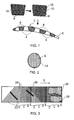
Figure 1 diagrammatically represents the formation of rod packs and assembly of the rod packs to form a core of a fan blade; -
Figure 2 is a sectional view of a rod of the rod packs; -
Figure 3 diagrammatically represents a reinforcement fabric for forming an outer skin of the fan blade; -
Figure 4 shows outer skin preforms formed from the fabric ofFigure 3 , in conjunction with the core represented inFigure 1 ; -
Figure 5 shows a completed fan blade; and -
Figure 6 shows an alternative core structure. - As shown in
Figure 1 , acore 2 of a fan blade for a turbofan engine is assembled fromcore components - As shown in
Figure 1 , thecomponents pack 4 made up of a plurality of reinforcingrods 8 embedded in aresin matrix 10. These packs are manufactured from small diameter composite rods, having a circular cross-section with a diameter in the range 1.5 - 3.5mm, and there may be 100 or more of therods 8 in eachpack 4. The rods may comprise high strength or intermediate modulus carbon fibres. The rods are cut to length (substantially the length of the finished fan blade) and embedded in a resin matrix. The matrix may comprise a curable syntactic paste or tough adhesive in which the rods may be embedded by vacuum casting. Alternatively, the rods may be embedded in a composite moulding compound in a compression moulding or injection moulding process. It will be appreciated fromFigure 1 that the cross-sectional shape of the pack has a generally quadrilateral form, of which two opposite faces are shaped to conform to the pressure and suction surfaces of the fan blade. The other two faces are oriented to provide webs between the pressure and suction surfaces of the fan blade, as will be described below. - After forming of the rod assemblies in the resin matrix, the assemblies are individually overbraided with a biaxial or triaxial overbraiding material, or are wrapped in
reinforcement fabric 12. - The overbraided or overwrapped rod packs are then assembled together, and with the
other components 6, to form thecore 2. Theother components 6 may be unreinforced mouldings formed from the resin used for the matrix of therod packs 4, for example a cured syntactic paste. Alternatively, they may be made from different materials, or they may be replaced byfurther rod packs 4. Thus in one embodiment, all of the components of thecore 2 may berod packs 4. - The
rods 8 themselves, as shown inFigure 2 , may be individually overwrapped by a suitable reinforcing material. For example they may be overwound under tension with pre-impregnated reinforcingfibres 14 which are subsequently cured. The purpose of overwinding is to suppress separation of the individual fibres of the rod under transverse tension occurring as a result of impact, axial loading or crack growth. Therods 8 themselves may be made from carbon fibres in a pultrusion process, and the overwinding may be carried out after pultrusion in a semi-continuous or batch process. - Furthermore, the
rods 8 may be additionally overwound or moulded with a wire or thread (not shown) in a spiral fashion to provide spacing projections which engage the corresponding projections, or main bodies, of adjacent rods in order to maintain a spacing between the main bodies of the rods to allow penetration of the resin matrix material during manufacture of thepacks 4. - In one embodiment the
core 2 shown inFigure 1 is provided with an outer skin to form the finished article. The outer skin may be formed by direct wrapping of the core by a suitable reinforcing material, but in one embodiment the skin is made up of twopreforms Figure 4 . Thepreforms Figure 4 . In order to maintain the integrity of thepreforms - The
preforms Figure 3 . In the embodiment shown inFigure 3 , the fabric comprises three plies of fibres, which may be carbon fibres oriented in different directions. In an alternative embodiment the fabric may comprise more than three plies of fibres. The plies of fibres are interconnected by stitching which is not shown inFigure 3 so as to make the fabric handleable. In the fabric shown inFigure 3 , there are twoouter plies 20, 22 extending respectively at +45° and -45° to the warp direction (indicated by an arrow X). There is afurther ply 24 of fibres which are disposed at 90° to the warp direction X. - As diagrammatically indicated in
Figure 3 , the area density of the 90° fibres varies along the warp direction. InFigure 3 , stepwise area density changes are represented by regions A, B, C and D, with the area density being highest in region A and lowest region D. Alternatively the area density may change gradually. It will be appreciated that the regions A to D are repeated along the warp direction X. In practice, the fabric is supplied in rolls, the length shown inFigure 3 being only a small part of a complete roll-supplied web. - Two cut-
outs Figure 3 , extending over a single length of the fabric embracing a single set of regions A to D. The cut-outs preforms fibres 24 thus extend chordwise of the finished blade. The shapes are cut, for example by laser cutting or ultrasonic cutting, under CNC control and deposited successively onto preform tooling in one axis of laminating, so minimising manual handling. In this construction method, the ply drop-offs (cut fibre terminations) would be of one fabric thickness. In the finished product, failure of the article by cracking is most likely to occur in the layer of 90° fibres. In the fabric shown inFigure 3 , the 90° fibres are disposed between the + 45° and -45°fibres 20, 22, and so fibre terminations along the span are mainly at ±45°, with the 90° fibre terminations being disposed within the textile reinforcement. Also, because the area density of 90° fibres decreases in the direction from the region A to the region D, relatively few 90° ply drop-offs are present at least in the regions C and D. - Because the skin formed from the
preforms - To avoid stress differentials in the lay-up of the
preforms 16, it is desirable for differently "handed" fabrics to be supplied for cutting-out of thepieces preform preform - Once the preforms have been made, they are placed on opposite sides of the
core 2, as shown inFigure 4 , and the resulting assembly is placed in a resin transfer moulding (RTM) mould. Resin is then injected into the mould to impregnate thepreforms individual components preforms components core 2. The resin is caused or allowed to cure, after which the finished moulding is removed from the mould and any secondary machining operations, for example to remove flash, to form the root region of the blade or to prepare the blade for attachment of other components, such as leading or trailing edge impact and erosion surfaces, as indicated at 30 and 32 inFigure 5 . - If desired, stitching or tufting may be applied after RTM moulding, in order to secure the outer skin to the
core 2 to enhance damage tolerance. In this process, a single needle and reinforcement thread of carbon fibre, glass fibre or aramid/para-aramid are pushed through the skin into thecore 2. The friction between the thread and the skin holds the thread in place as the needle is withdrawn, forming a loop or tuft bridging the skin andcore 2. - In the finished fan blade represented in
Figure 5 , therods 8 which support centrifugal forces applied to the blade are disposed internally of the blade and so are protected from impact damage by the skin formed by thepreforms packs 4 are made up of the closelypacked rods 8, rather than a laminar arrangement of reinforcing fabrics, damage extending into thecore 2 cannot easily propagate through thecore 2 because there are no straight "runs" betweenadjacent rods 8. This is in contrast to a traditionally laid-up blade using fabric reinforcements where cracks can propagate between adjacent layers of the fabric. - Furthermore, the
tough matrix 10 within the which therods 8 are embedded is effective in transferring loads between adjacent rods, while accepting relatively high strain without failure. - The resin forming the
matrix 10 can be selected or formulated to provide desired damping characteristics in the structure. The material may be a syntactic gap filling polyurethane or epoxy paste, or a syntactic film such as may be used in the manufacture of honeycombed sandwich panel composites for the purpose of stabilising or joining core materials. The material may also be of thermoplastic composition. - As an alternative to using such a material, the
packs 4 may be formed by compression moulding therods 8 within a bulk moulding compound containing chopped fibre, so creating a quasi-homogenous composite matrix surrounding therods 8. The chopped fibre may be glass, carbon or a hybrid of the two. The matrix resin is preferably compatible with therods 8 themselves. A suitable material is available under the name HexMC®, available from Hexcel Corporation of Stamford, Connecticut, USA. - In the blade shown in
Figure 5 thecomponents adjacent components webs 34 which provide a shear connection between the pressure and suction surfaces of the fan blade. The overwinding 12 of thepacks preforms - The skins formed from the
preforms preforms - When the skin is formed from preforms 16, 18 as described in
Figure 4 , the preforms are preferably compressed, before application to thecore 2, to substantially their final thickness, or at least to a thickness not more than 10% above the final moulded thickness in the finished fan blade. - In an alternative embodiment, as shown in
Figure 6 , all of the components of the core comprise rod packs 4. Thepacks 4 are not overwound as described with reference toFigure 1 , but are instead compression moulded together to form thecore 2 along with a chopped pre-preg sheet moulding compound, or similar material. Thus, the rod packs 4 are assembled together with such asheet moulding compound 36 which is deflected alternately aroundadjacent packs 4. Thesheet moulding compound 36 thus forms shear webs extending across the core, to provide a shear connection between the pressure and suction sides of the finished blade. - As in the embodiment shown in
Figures 4 and 5 , thecore 2 shown inFigure 6 may be provided with a skin, either formed from preforms 16, 18 as shown inFigure 4 , or in any alternative manner. For example, thepreforms preforms core 2 the assembly would be subjected to a final compression moulding step which would integrate the skin with thewebs 38 formed by the bulk moulding compound between adjacent rod packs 4. - As shown in
Figure 6 , outwardly facing surfaces of the sheet moulding compound which, with the rod packs 4, form thecore 2 may be provided withsmall projections 40 of defined height. These projections serve, during the compression moulding step, to centre the core within the mould so as to establish a required thickness of the moulding compound applied over thecore 2 to form the skin of the fan blade. This measure would thus prevent the thickness of each skin from falling below a minimum value during the compression moulding step. - While the unnotched in-plane properties of chopped pre-preg compression moulding compounds may be inferior to those of conventional continuous fibre quasi-isotropic laminates as described above with reference to
Figures 3 and4 , the notched tensile and compression properties are similar. - Of course, the
core 2 shown inFigure 6 could have an outer skin applied to it by use of compressed preforms of multi-axial warp knit fabric as described above with reference toFigures 3 and4 , in which case theprotrusions 40 would also provide thickness control between the skin of the fan blade and the web structure constituted by themoulding compound 36. - Although the fabric shown in
Figure 3 is referred to as being formed from carbon fibres it will be appreciated that other suitable fibre reinforcement materials may be used. For example, S-glass fibre available from Owens-Corning of Toledo, Ohio, USA, or other high-strength fibres may be used. A more conventional broadly isotropic lay-up construction may be used to achieve an adequate level of damage tolerance. - Although the present invention has been described in connection with the manufacture of a fan blade for a turbofan engine, it will be appreciated that other articles could be manufactured in the same manner. For example, blades for open-rotor and propeller structures (for example turbo prop, ducted fans and other such turbomachinery) could be manufactured by the processes described with reference to
Figures 1 to 6 . For such articles, and similar articles with relatively slender and deep sections, may have an outer skin formed using a biaxial/triaxial braided reinforcement over a core comprising or includingreinforcement rods 8 in a resin matrix. - The manufacturing process may also be suitable for static aerofoil structures and non-aerofoil components, such as blade containment structures for gas turbine engines or, indeed, any components where it is desirable to separate and protect the integrity of elements which provide axial or radial strength of the component from specific damage threats.
Claims (15)
- An article formed from a composite material, the article comprising abutting core components (4,6), wherein at least one of the core components (4) comprises a pack of reinforcement rods (8) disposed parallel to each other and embedded in a resin matrix (10), each rod (8) comprising a resin-bonded bundle of reinforcement fibres.
- An article as claimed in claim 1, in which the cross-section of each rod (8) has a transverse dimension which is not less than 1.5mm and not more than 3.5mm.
- An article as claimed in claim 1 or claim 2 in which the reinforcement fibres comprise carbon fibres.
- An article as claimed in any one of the preceding claims, in which the resin matrix (10) comprises a cured syntactic material.
- An article as claimed in any one of the preceding claims, in which the or each pack (4) comprises not less than 100 of the reinforcement rods (8).
- An article as claimed in any one of the preceding claims, in which each reinforcement rod (8) is provided with an overwinding (12) of reinforcing fibres in a resin matrix.
- An article as claimed in any one of the preceding claims, in which each reinforcing rod (8) comprises a main body having a spacing projection for spacing the main bodies of adjacent rods (8) from one another.
- An article as claimed in claim 7, in which the projection is of spiral form about the longitudinal axis of the respective rod (8).
- An article as claimed in any one of the preceding claims, in which the rod pack (4) or packs (4,6) constitute a core (2) of the article which is provided with an outer layer enclosing the core (2).
- An article as claimed in claim 9, in which the outer layer comprises reinforcement fibres in a resin matrix.
- An article as claimed in claim 10, in which the fibres are disposed in fabric layers.
- An article as claimed in claim 11, in which each fabric layer comprises a multi-axial warp knit fabric.
- An article as claimed in claim 12, in which the multi-axial warp knit fabric comprises fibres oriented at +45°/90°/-45° with respect to the lengths of the rods.
- An article as claimed in claim 13, in which the area weight of the fibres oriented at 90° varies in the lengthwise direction of the rods.
- A method of manufacturing an article of composite material, the method comprising:assembling a plurality of reinforcement rods (8) into a pack (4) in which the rods (8) are parallel to each other, each rod (8) comprising a resin-bonded bundle of reinforcement fibres;impregnating the pack with a first settable or curable composition, and causing or allowing the composition to set or cure to form a resin matrix (10) in which the rods (8) are embedded;providing a fibre wrapping around the pack to form a core component (4);assembling a core (2) of the article, the core including abutting core components (4,6);assembling a fibre reinforcement over the core (2);placing the core (2) with the assembled fibre reinforcement in a mould corresponding to the desired shape of the article; andadmitting a second settable or curable composition into the mould and causing or allowing the second composition to set or cure.
Applications Claiming Priority (1)
| Application Number | Priority Date | Filing Date | Title |
|---|---|---|---|
| GB0805604A GB2458685B (en) | 2008-03-28 | 2008-03-28 | An article formed from a composite material |
Publications (3)
| Publication Number | Publication Date |
|---|---|
| EP2105579A2 true EP2105579A2 (en) | 2009-09-30 |
| EP2105579A3 EP2105579A3 (en) | 2011-05-04 |
| EP2105579B1 EP2105579B1 (en) | 2013-11-06 |
Family
ID=39386875
Family Applications (1)
| Application Number | Title | Priority Date | Filing Date |
|---|---|---|---|
| EP20090250356 Active EP2105579B1 (en) | 2008-03-28 | 2009-02-12 | An article formed from a composite material |
Country Status (4)
| Country | Link |
|---|---|
| US (1) | US8109734B2 (en) |
| EP (1) | EP2105579B1 (en) |
| JP (1) | JP5542359B2 (en) |
| GB (1) | GB2458685B (en) |
Cited By (38)
| Publication number | Priority date | Publication date | Assignee | Title |
|---|---|---|---|---|
| WO2011089312A1 (en) * | 2010-01-21 | 2011-07-28 | Runtech Systems Oy | Method for manufacturing the impeller of a centrifugal compressor |
| FR2964411A1 (en) * | 2010-09-06 | 2012-03-09 | Messier Dowty Sa | DUST OF TURBOREACTOR, IN PARTICULAR A DRAWER OF RECTIFIER, AND TURBOJET RECEIVING SUCH AS AUBES |
| WO2013093258A1 (en) * | 2011-11-24 | 2013-06-27 | Aircelle | Aircraft engine air flow straightening vane and associated flow straightening structure |
| FR3017650A1 (en) * | 2014-02-14 | 2015-08-21 | Safran | RECTIFIER BOLT FOR HYBRID STRUCTURE GAS TURBINE ENGINE |
| EP2831377A4 (en) * | 2012-03-26 | 2016-04-27 | United Technologies Corp | Hybrid airfoil for a gas turbine engine |
| EP3406434A1 (en) * | 2017-05-22 | 2018-11-28 | Ratier-Figeac SAS | Composite blade and method of manufacture |
| US10309238B2 (en) | 2016-11-17 | 2019-06-04 | United Technologies Corporation | Turbine engine component with geometrically segmented coating section and cooling passage |
| US10309226B2 (en) | 2016-11-17 | 2019-06-04 | United Technologies Corporation | Airfoil having panels |
| US10408090B2 (en) | 2016-11-17 | 2019-09-10 | United Technologies Corporation | Gas turbine engine article with panel retained by preloaded compliant member |
| US10408082B2 (en) | 2016-11-17 | 2019-09-10 | United Technologies Corporation | Airfoil with retention pocket holding airfoil piece |
| US10415407B2 (en) | 2016-11-17 | 2019-09-17 | United Technologies Corporation | Airfoil pieces secured with endwall section |
| EP3543002A1 (en) * | 2018-03-09 | 2019-09-25 | Rolls-Royce plc | A method of manufacturing a fan blade and a fan blade |
| US10428663B2 (en) | 2016-11-17 | 2019-10-01 | United Technologies Corporation | Airfoil with tie member and spring |
| US10428658B2 (en) | 2016-11-17 | 2019-10-01 | United Technologies Corporation | Airfoil with panel fastened to core structure |
| US10436062B2 (en) | 2016-11-17 | 2019-10-08 | United Technologies Corporation | Article having ceramic wall with flow turbulators |
| US10436049B2 (en) | 2016-11-17 | 2019-10-08 | United Technologies Corporation | Airfoil with dual profile leading end |
| US10458262B2 (en) | 2016-11-17 | 2019-10-29 | United Technologies Corporation | Airfoil with seal between endwall and airfoil section |
| US10480331B2 (en) | 2016-11-17 | 2019-11-19 | United Technologies Corporation | Airfoil having panel with geometrically segmented coating |
| US10480334B2 (en) | 2016-11-17 | 2019-11-19 | United Technologies Corporation | Airfoil with geometrically segmented coating section |
| US10502070B2 (en) | 2016-11-17 | 2019-12-10 | United Technologies Corporation | Airfoil with laterally insertable baffle |
| US10570765B2 (en) | 2016-11-17 | 2020-02-25 | United Technologies Corporation | Endwall arc segments with cover across joint |
| US10598025B2 (en) | 2016-11-17 | 2020-03-24 | United Technologies Corporation | Airfoil with rods adjacent a core structure |
| US10598029B2 (en) | 2016-11-17 | 2020-03-24 | United Technologies Corporation | Airfoil with panel and side edge cooling |
| US10605088B2 (en) | 2016-11-17 | 2020-03-31 | United Technologies Corporation | Airfoil endwall with partial integral airfoil wall |
| US10662782B2 (en) | 2016-11-17 | 2020-05-26 | Raytheon Technologies Corporation | Airfoil with airfoil piece having axial seal |
| US10662779B2 (en) | 2016-11-17 | 2020-05-26 | Raytheon Technologies Corporation | Gas turbine engine component with degradation cooling scheme |
| US10677079B2 (en) | 2016-11-17 | 2020-06-09 | Raytheon Technologies Corporation | Airfoil with ceramic airfoil piece having internal cooling circuit |
| US10677091B2 (en) | 2016-11-17 | 2020-06-09 | Raytheon Technologies Corporation | Airfoil with sealed baffle |
| US10711616B2 (en) | 2016-11-17 | 2020-07-14 | Raytheon Technologies Corporation | Airfoil having endwall panels |
| US10711794B2 (en) | 2016-11-17 | 2020-07-14 | Raytheon Technologies Corporation | Airfoil with geometrically segmented coating section having mechanical secondary bonding feature |
| US10711624B2 (en) | 2016-11-17 | 2020-07-14 | Raytheon Technologies Corporation | Airfoil with geometrically segmented coating section |
| US10731495B2 (en) | 2016-11-17 | 2020-08-04 | Raytheon Technologies Corporation | Airfoil with panel having perimeter seal |
| US10746038B2 (en) | 2016-11-17 | 2020-08-18 | Raytheon Technologies Corporation | Airfoil with airfoil piece having radial seal |
| US10767487B2 (en) | 2016-11-17 | 2020-09-08 | Raytheon Technologies Corporation | Airfoil with panel having flow guide |
| US10808554B2 (en) | 2016-11-17 | 2020-10-20 | Raytheon Technologies Corporation | Method for making ceramic turbine engine article |
| EP3798418A1 (en) * | 2019-09-17 | 2021-03-31 | Rolls-Royce plc | A weaved composite gas turbine vane and method |
| WO2022079415A1 (en) * | 2020-10-16 | 2022-04-21 | Airbus Operations Limited | Method of manufacturing aircraft aerofoil |
| US11413831B2 (en) | 2019-09-17 | 2022-08-16 | Rolls-Royce Plc | Tool for compacting a composite preform assembly and a method for the same |
Families Citing this family (27)
| Publication number | Priority date | Publication date | Assignee | Title |
|---|---|---|---|---|
| CN101666290B (en) * | 2009-10-14 | 2011-11-09 | 黄争鸣 | Wind turbine blade structure, machining method and applications thereof |
| GB201001527D0 (en) * | 2010-01-29 | 2010-03-17 | Blade Dynamics Ltd | A blade for a turbine operating in water |
| FR2963949A1 (en) * | 2010-08-18 | 2012-02-24 | Aircelle Sa | BEAM PARTICULARLY FOR THRUST INVERTER WITH GRILLS |
| US8651419B2 (en) * | 2011-07-18 | 2014-02-18 | The Boeing Company | Flexible truss frame and method of making the same |
| DK2551512T3 (en) * | 2011-07-27 | 2014-07-21 | Alstom Renovables Espana Sl | Connecting device on a wind turbine blade |
| GB201215004D0 (en) | 2012-08-23 | 2012-10-10 | Blade Dynamics Ltd | Wind turbine tower |
| GB201217210D0 (en) | 2012-09-26 | 2012-11-07 | Blade Dynamics Ltd | A metod of forming a structural connection between a spar cap fairing for a wind turbine blade |
| GB201217212D0 (en) | 2012-09-26 | 2012-11-07 | Blade Dynamics Ltd | Windturbine blade |
| GB2508656B (en) * | 2012-12-10 | 2015-08-05 | Rolls Royce Plc | Improved joint structure and method |
| US10458428B2 (en) * | 2013-09-09 | 2019-10-29 | United Technologies Corporation | Fan blades and manufacture methods |
| KR102185596B1 (en) | 2014-05-05 | 2020-12-02 | 호르톤 인코포레이티드 | Composite fan |
| US9359055B2 (en) | 2014-08-05 | 2016-06-07 | Confluence Outdoor, Llc | Composite paddles |
| US10677259B2 (en) | 2016-05-06 | 2020-06-09 | General Electric Company | Apparatus and system for composite fan blade with fused metal lead edge |
| US11020910B2 (en) * | 2016-05-13 | 2021-06-01 | Bell Helicopter Textron Inc. | System and method of constructing composite structures without tooling dams |
| US10570917B2 (en) | 2016-08-01 | 2020-02-25 | United Technologies Corporation | Fan blade with composite cover |
| US10746045B2 (en) | 2018-10-16 | 2020-08-18 | General Electric Company | Frangible gas turbine engine airfoil including a retaining member |
| US11111815B2 (en) | 2018-10-16 | 2021-09-07 | General Electric Company | Frangible gas turbine engine airfoil with fusion cavities |
| US10837286B2 (en) | 2018-10-16 | 2020-11-17 | General Electric Company | Frangible gas turbine engine airfoil with chord reduction |
| US11149558B2 (en) | 2018-10-16 | 2021-10-19 | General Electric Company | Frangible gas turbine engine airfoil with layup change |
| US10760428B2 (en) | 2018-10-16 | 2020-09-01 | General Electric Company | Frangible gas turbine engine airfoil |
| US11434781B2 (en) | 2018-10-16 | 2022-09-06 | General Electric Company | Frangible gas turbine engine airfoil including an internal cavity |
| US11679576B2 (en) | 2019-02-15 | 2023-06-20 | Tpi Composites, Inc. | Composite rods for stabilization of composite laminates |
| GB201913392D0 (en) * | 2019-09-17 | 2019-10-30 | Rolls Royce Plc | A stator vane ring and a method of manufacture |
| CN112265288B (en) * | 2020-09-02 | 2022-09-02 | 长春长光宇航复合材料有限公司 | Preparation method of single-side reinforced structure carbon fiber composite material plate |
| CN113263250B (en) * | 2021-04-20 | 2022-07-19 | 上海交通大学 | Composite manufacturing method of metal reinforced edge of aircraft engine fan blade |
| US11674399B2 (en) | 2021-07-07 | 2023-06-13 | General Electric Company | Airfoil arrangement for a gas turbine engine utilizing a shape memory alloy |
| US11668317B2 (en) | 2021-07-09 | 2023-06-06 | General Electric Company | Airfoil arrangement for a gas turbine engine utilizing a shape memory alloy |
Citations (1)
| Publication number | Priority date | Publication date | Assignee | Title |
|---|---|---|---|---|
| US5876659A (en) | 1993-06-25 | 1999-03-02 | Hitachi, Ltd. | Process for producing fiber reinforced composite |
Family Cites Families (14)
| Publication number | Priority date | Publication date | Assignee | Title |
|---|---|---|---|---|
| GB1291718A (en) * | 1969-12-19 | 1972-10-04 | Rolls Royce | Aerofoil-shaped blade for a fluid flow machine |
| JPS5018002Y1 (en) * | 1972-01-25 | 1975-06-03 | ||
| US4051289A (en) * | 1976-04-12 | 1977-09-27 | General Electric Company | Composite airfoil construction |
| FR2658090B1 (en) * | 1990-02-15 | 1992-04-30 | Salomon Sa | PROCESS FOR ASSEMBLING A SKI BY MOLDING, AND SKI STRUCTURE OBTAINED BY THIS PROCESS. |
| US5057257A (en) * | 1990-02-20 | 1991-10-15 | Quantum Composites, Inc. | Method of transfer molding fiber-reinforced resin bolt products |
| JPH05176656A (en) * | 1991-12-26 | 1993-07-20 | Sumitomo Rubber Ind Ltd | Rodlike reinforcing elastic body |
| JPH05318472A (en) * | 1992-05-22 | 1993-12-03 | Sekisui Chem Co Ltd | Fiber-reinforced thermoplastic resin sheet |
| EP0594131A1 (en) * | 1992-10-21 | 1994-04-27 | The Budd Company | Composite chassis structure and method of manufacture |
| US5993713A (en) * | 1992-12-01 | 1999-11-30 | De La Puerta; Enrique | Reinforced composite shapes and method and apparatus for their manufacture |
| JPH07223876A (en) * | 1993-06-25 | 1995-08-22 | Hitachi Ltd | Fiber-reinforced composite material, production thereof and member using the same |
| US5809805A (en) * | 1996-09-03 | 1998-09-22 | Mcdonnell Douglas Corporation | Warp/knit reinforced structural fabric |
| JP4067855B2 (en) * | 2002-04-04 | 2008-03-26 | 福井ファイバーテック株式会社 | Fiber-reinforced resin plate with improved bending strength in the longitudinal direction |
| US20040145079A1 (en) * | 2003-01-27 | 2004-07-29 | Yung-Kun Lin | Composite material member having reinforcement ribs and method for making the same |
| GB0428368D0 (en) * | 2004-12-24 | 2005-02-02 | Rolls Royce Plc | A composite blade |
-
2008
- 2008-03-28 GB GB0805604A patent/GB2458685B/en active Active
-
2009
- 2009-02-12 EP EP20090250356 patent/EP2105579B1/en active Active
- 2009-02-24 US US12/379,530 patent/US8109734B2/en active Active
- 2009-03-30 JP JP2009082497A patent/JP5542359B2/en not_active Expired - Fee Related
Patent Citations (1)
| Publication number | Priority date | Publication date | Assignee | Title |
|---|---|---|---|---|
| US5876659A (en) | 1993-06-25 | 1999-03-02 | Hitachi, Ltd. | Process for producing fiber reinforced composite |
Cited By (52)
| Publication number | Priority date | Publication date | Assignee | Title |
|---|---|---|---|---|
| WO2011089312A1 (en) * | 2010-01-21 | 2011-07-28 | Runtech Systems Oy | Method for manufacturing the impeller of a centrifugal compressor |
| US9492970B2 (en) | 2010-01-21 | 2016-11-15 | Runtech Systems Oy | Method for manufacturing the impeller of a centrifugal compressor |
| FR2964411A1 (en) * | 2010-09-06 | 2012-03-09 | Messier Dowty Sa | DUST OF TURBOREACTOR, IN PARTICULAR A DRAWER OF RECTIFIER, AND TURBOJET RECEIVING SUCH AS AUBES |
| WO2012032016A1 (en) * | 2010-09-06 | 2012-03-15 | Messier-Bugatti-Dowty | Turbojet engine blade, in particular a guide blade, and turbojet engine receiving such blades |
| RU2544102C2 (en) * | 2010-09-06 | 2015-03-10 | Эрсэль | Vane of turbojet engine, in particular, vane of outlet straightener, and turbojet engine with such vanes |
| WO2013093258A1 (en) * | 2011-11-24 | 2013-06-27 | Aircelle | Aircraft engine air flow straightening vane and associated flow straightening structure |
| US9915157B2 (en) | 2011-11-24 | 2018-03-13 | Safran Aircraft Engines | Aircraft engine air flow straightening vane and associated flow straightening structure |
| EP2831377A4 (en) * | 2012-03-26 | 2016-04-27 | United Technologies Corp | Hybrid airfoil for a gas turbine engine |
| US9835033B2 (en) | 2012-03-26 | 2017-12-05 | United Technologies Corporation | Hybrid airfoil for a gas turbine engine |
| FR3017650A1 (en) * | 2014-02-14 | 2015-08-21 | Safran | RECTIFIER BOLT FOR HYBRID STRUCTURE GAS TURBINE ENGINE |
| US10598025B2 (en) | 2016-11-17 | 2020-03-24 | United Technologies Corporation | Airfoil with rods adjacent a core structure |
| US10677079B2 (en) | 2016-11-17 | 2020-06-09 | Raytheon Technologies Corporation | Airfoil with ceramic airfoil piece having internal cooling circuit |
| US10408090B2 (en) | 2016-11-17 | 2019-09-10 | United Technologies Corporation | Gas turbine engine article with panel retained by preloaded compliant member |
| US10408082B2 (en) | 2016-11-17 | 2019-09-10 | United Technologies Corporation | Airfoil with retention pocket holding airfoil piece |
| US10415407B2 (en) | 2016-11-17 | 2019-09-17 | United Technologies Corporation | Airfoil pieces secured with endwall section |
| US11333036B2 (en) | 2016-11-17 | 2022-05-17 | Raytheon Technologies | Article having ceramic wall with flow turbulators |
| US11319817B2 (en) | 2016-11-17 | 2022-05-03 | Raytheon Technologies Corporation | Airfoil with panel and side edge cooling |
| US10428663B2 (en) | 2016-11-17 | 2019-10-01 | United Technologies Corporation | Airfoil with tie member and spring |
| US10428658B2 (en) | 2016-11-17 | 2019-10-01 | United Technologies Corporation | Airfoil with panel fastened to core structure |
| US10436062B2 (en) | 2016-11-17 | 2019-10-08 | United Technologies Corporation | Article having ceramic wall with flow turbulators |
| US10436049B2 (en) | 2016-11-17 | 2019-10-08 | United Technologies Corporation | Airfoil with dual profile leading end |
| US10458262B2 (en) | 2016-11-17 | 2019-10-29 | United Technologies Corporation | Airfoil with seal between endwall and airfoil section |
| US10480331B2 (en) | 2016-11-17 | 2019-11-19 | United Technologies Corporation | Airfoil having panel with geometrically segmented coating |
| US10480334B2 (en) | 2016-11-17 | 2019-11-19 | United Technologies Corporation | Airfoil with geometrically segmented coating section |
| US10502070B2 (en) | 2016-11-17 | 2019-12-10 | United Technologies Corporation | Airfoil with laterally insertable baffle |
| US10570765B2 (en) | 2016-11-17 | 2020-02-25 | United Technologies Corporation | Endwall arc segments with cover across joint |
| US10309238B2 (en) | 2016-11-17 | 2019-06-04 | United Technologies Corporation | Turbine engine component with geometrically segmented coating section and cooling passage |
| US10598029B2 (en) | 2016-11-17 | 2020-03-24 | United Technologies Corporation | Airfoil with panel and side edge cooling |
| US10605088B2 (en) | 2016-11-17 | 2020-03-31 | United Technologies Corporation | Airfoil endwall with partial integral airfoil wall |
| US10662782B2 (en) | 2016-11-17 | 2020-05-26 | Raytheon Technologies Corporation | Airfoil with airfoil piece having axial seal |
| US10662779B2 (en) | 2016-11-17 | 2020-05-26 | Raytheon Technologies Corporation | Gas turbine engine component with degradation cooling scheme |
| US10309226B2 (en) | 2016-11-17 | 2019-06-04 | United Technologies Corporation | Airfoil having panels |
| US10677091B2 (en) | 2016-11-17 | 2020-06-09 | Raytheon Technologies Corporation | Airfoil with sealed baffle |
| US10711616B2 (en) | 2016-11-17 | 2020-07-14 | Raytheon Technologies Corporation | Airfoil having endwall panels |
| US10711794B2 (en) | 2016-11-17 | 2020-07-14 | Raytheon Technologies Corporation | Airfoil with geometrically segmented coating section having mechanical secondary bonding feature |
| US10711624B2 (en) | 2016-11-17 | 2020-07-14 | Raytheon Technologies Corporation | Airfoil with geometrically segmented coating section |
| US10731495B2 (en) | 2016-11-17 | 2020-08-04 | Raytheon Technologies Corporation | Airfoil with panel having perimeter seal |
| US11149573B2 (en) | 2016-11-17 | 2021-10-19 | Raytheon Technologies Corporation | Airfoil with seal between end wall and airfoil section |
| US10746038B2 (en) | 2016-11-17 | 2020-08-18 | Raytheon Technologies Corporation | Airfoil with airfoil piece having radial seal |
| US10767487B2 (en) | 2016-11-17 | 2020-09-08 | Raytheon Technologies Corporation | Airfoil with panel having flow guide |
| US10808554B2 (en) | 2016-11-17 | 2020-10-20 | Raytheon Technologies Corporation | Method for making ceramic turbine engine article |
| US11092016B2 (en) | 2016-11-17 | 2021-08-17 | Raytheon Technologies Corporation | Airfoil with dual profile leading end |
| US10746030B2 (en) | 2017-05-22 | 2020-08-18 | Ratier-Figeac Sas | Composite blade and method of manufacture |
| EP3406434A1 (en) * | 2017-05-22 | 2018-11-28 | Ratier-Figeac SAS | Composite blade and method of manufacture |
| US10858944B2 (en) | 2018-03-09 | 2020-12-08 | Rolls-Royce Plc | Method of manufacturing a fan blade and a fan blade |
| US11187084B2 (en) | 2018-03-09 | 2021-11-30 | Rolls-Royce Plc | Method of manufacturing a fan blade and a fan blade |
| EP3543002A1 (en) * | 2018-03-09 | 2019-09-25 | Rolls-Royce plc | A method of manufacturing a fan blade and a fan blade |
| US11441429B2 (en) | 2018-03-09 | 2022-09-13 | Rolls-Royce Plc | Composite fan blade and manufacturing method thereof |
| EP3798418A1 (en) * | 2019-09-17 | 2021-03-31 | Rolls-Royce plc | A weaved composite gas turbine vane and method |
| US11413831B2 (en) | 2019-09-17 | 2022-08-16 | Rolls-Royce Plc | Tool for compacting a composite preform assembly and a method for the same |
| US11415008B2 (en) | 2019-09-17 | 2022-08-16 | Rolls-Royce Plc | Vane |
| WO2022079415A1 (en) * | 2020-10-16 | 2022-04-21 | Airbus Operations Limited | Method of manufacturing aircraft aerofoil |
Also Published As
| Publication number | Publication date |
|---|---|
| US20090246446A1 (en) | 2009-10-01 |
| JP2009264374A (en) | 2009-11-12 |
| GB2458685A (en) | 2009-09-30 |
| GB2458685B (en) | 2010-05-12 |
| EP2105579B1 (en) | 2013-11-06 |
| EP2105579A3 (en) | 2011-05-04 |
| US8109734B2 (en) | 2012-02-07 |
| JP5542359B2 (en) | 2014-07-09 |
| GB0805604D0 (en) | 2008-04-30 |
Similar Documents
| Publication | Publication Date | Title |
|---|---|---|
| EP2105579B1 (en) | An article formed from a composite material | |
| US5279892A (en) | Composite airfoil with woven insert | |
| EP2441571B1 (en) | Proces for manufacturing a composite component | |
| JP5974111B2 (en) | Composite storage case for gas turbine fan and manufacturing method thereof | |
| US6613392B2 (en) | Method for making a fiber reinforced composite article and product | |
| CA2606810C (en) | Method for the manufacturing of a hollow fiber reinforced structural member | |
| US20140010662A1 (en) | Composite airfoil with integral platform | |
| US9309772B2 (en) | Hybrid turbine blade including multiple insert sections | |
| CA2889366C (en) | Cylindrical case and manufacturing method of cyclindrical case | |
| US20160031182A1 (en) | Composite flange with three-dimensional weave architecture | |
| CN113623016B (en) | Woven blade and vane with dovetail root | |
| US20110045276A1 (en) | Fiber Reinforced Plastic-Structure and a Method to Produce the Fiber Reinforced Plastic-Structure | |
| CA2875029A1 (en) | Composite structure with low density core and composite stitching reinforcement | |
| US20160186774A1 (en) | Process of producing a thermoplastic-fiber composite and fan blades formed therefrom | |
| US20160101591A1 (en) | Composite article | |
| US10746030B2 (en) | Composite blade and method of manufacture | |
| EP2543506B1 (en) | Layered composite component | |
| GB2571180A (en) | Composite hollow blade and a method of forming the composite hollow blade | |
| EP2955005B1 (en) | A composite structure and a method of fabricating the same | |
| US20180106268A1 (en) | Blade component |
Legal Events
| Date | Code | Title | Description |
|---|---|---|---|
| PUAI | Public reference made under article 153(3) epc to a published international application that has entered the european phase |
Free format text: ORIGINAL CODE: 0009012 |
|
| AK | Designated contracting states |
Kind code of ref document: A2 Designated state(s): AT BE BG CH CY CZ DE DK EE ES FI FR GB GR HR HU IE IS IT LI LT LU LV MC MK MT NL NO PL PT RO SE SI SK TR |
|
| AX | Request for extension of the european patent |
Extension state: AL BA RS |
|
| PUAL | Search report despatched |
Free format text: ORIGINAL CODE: 0009013 |
|
| AK | Designated contracting states |
Kind code of ref document: A3 Designated state(s): AT BE BG CH CY CZ DE DK EE ES FI FR GB GR HR HU IE IS IT LI LT LU LV MC MK MT NL NO PL PT RO SE SI SK TR |
|
| AX | Request for extension of the european patent |
Extension state: AL BA RS |
|
| RIC1 | Information provided on ipc code assigned before grant |
Ipc: F01D 5/28 20060101ALI20110325BHEP Ipc: F01D 5/14 20060101AFI20090708BHEP |
|
| 17P | Request for examination filed |
Effective date: 20110831 |
|
| AKX | Designation fees paid |
Designated state(s): DE FR GB |
|
| 17Q | First examination report despatched |
Effective date: 20120511 |
|
| GRAP | Despatch of communication of intention to grant a patent |
Free format text: ORIGINAL CODE: EPIDOSNIGR1 |
|
| INTG | Intention to grant announced |
Effective date: 20130816 |
|
| GRAS | Grant fee paid |
Free format text: ORIGINAL CODE: EPIDOSNIGR3 |
|
| GRAA | (expected) grant |
Free format text: ORIGINAL CODE: 0009210 |
|
| AK | Designated contracting states |
Kind code of ref document: B1 Designated state(s): DE FR GB |
|
| REG | Reference to a national code |
Ref country code: GB Ref legal event code: FG4D |
|
| REG | Reference to a national code |
Ref country code: DE Ref legal event code: R096 Ref document number: 602009019868 Country of ref document: DE Effective date: 20140109 |
|
| REG | Reference to a national code |
Ref country code: DE Ref legal event code: R097 Ref document number: 602009019868 Country of ref document: DE |
|
| PLBE | No opposition filed within time limit |
Free format text: ORIGINAL CODE: 0009261 |
|
| STAA | Information on the status of an ep patent application or granted ep patent |
Free format text: STATUS: NO OPPOSITION FILED WITHIN TIME LIMIT |
|
| 26N | No opposition filed |
Effective date: 20140807 |
|
| REG | Reference to a national code |
Ref country code: DE Ref legal event code: R097 Ref document number: 602009019868 Country of ref document: DE Effective date: 20140807 |
|
| REG | Reference to a national code |
Ref country code: FR Ref legal event code: PLFP Year of fee payment: 8 |
|
| REG | Reference to a national code |
Ref country code: FR Ref legal event code: PLFP Year of fee payment: 9 |
|
| REG | Reference to a national code |
Ref country code: FR Ref legal event code: CA Effective date: 20170517 |
|
| REG | Reference to a national code |
Ref country code: FR Ref legal event code: PLFP Year of fee payment: 10 |
|
| PGFP | Annual fee paid to national office [announced via postgrant information from national office to epo] |
Ref country code: ES Payment date: 20190305 Year of fee payment: 5 |
|
| PGFP | Annual fee paid to national office [announced via postgrant information from national office to epo] |
Ref country code: FR Payment date: 20190225 Year of fee payment: 11 |
|
| REG | Reference to a national code |
Ref country code: DE Ref legal event code: R119 Ref document number: 602009019868 Country of ref document: DE |
|
| PG25 | Lapsed in a contracting state [announced via postgrant information from national office to epo] |
Ref country code: FR Free format text: LAPSE BECAUSE OF NON-PAYMENT OF DUE FEES Effective date: 20200229 Ref country code: DE Free format text: LAPSE BECAUSE OF NON-PAYMENT OF DUE FEES Effective date: 20200901 |
|
| PGFP | Annual fee paid to national office [announced via postgrant information from national office to epo] |
Ref country code: GB Payment date: 20230214 Year of fee payment: 15 |
|
| P01 | Opt-out of the competence of the unified patent court (upc) registered |
Effective date: 20230528 |