EP2105398A2 - Yarn Winding Apparatus - Google Patents
Yarn Winding Apparatus Download PDFInfo
- Publication number
- EP2105398A2 EP2105398A2 EP09154184A EP09154184A EP2105398A2 EP 2105398 A2 EP2105398 A2 EP 2105398A2 EP 09154184 A EP09154184 A EP 09154184A EP 09154184 A EP09154184 A EP 09154184A EP 2105398 A2 EP2105398 A2 EP 2105398A2
- Authority
- EP
- European Patent Office
- Prior art keywords
- yarn
- reference position
- traverse
- package
- section
- Prior art date
- Legal status (The legal status is an assumption and is not a legal conclusion. Google has not performed a legal analysis and makes no representation as to the accuracy of the status listed.)
- Withdrawn
Links
Images


Classifications
-
- B—PERFORMING OPERATIONS; TRANSPORTING
- B65—CONVEYING; PACKING; STORING; HANDLING THIN OR FILAMENTARY MATERIAL
- B65H—HANDLING THIN OR FILAMENTARY MATERIAL, e.g. SHEETS, WEBS, CABLES
- B65H54/00—Winding, coiling, or depositing filamentary material
- B65H54/02—Winding and traversing material on to reels, bobbins, tubes, or like package cores or formers
- B65H54/28—Traversing devices; Package-shaping arrangements
- B65H54/2827—Traversing devices with a pivotally mounted guide arm
-
- B—PERFORMING OPERATIONS; TRANSPORTING
- B65—CONVEYING; PACKING; STORING; HANDLING THIN OR FILAMENTARY MATERIAL
- B65H—HANDLING THIN OR FILAMENTARY MATERIAL, e.g. SHEETS, WEBS, CABLES
- B65H54/00—Winding, coiling, or depositing filamentary material
- B65H54/02—Winding and traversing material on to reels, bobbins, tubes, or like package cores or formers
- B65H54/28—Traversing devices; Package-shaping arrangements
- B65H54/2884—Microprocessor-controlled traversing devices in so far the control is not special to one of the traversing devices of groups B65H54/2803 - B65H54/325 or group B65H54/38
- B65H54/2887—Microprocessor-controlled traversing devices in so far the control is not special to one of the traversing devices of groups B65H54/2803 - B65H54/325 or group B65H54/38 detecting the position of the yarn guide
-
- B—PERFORMING OPERATIONS; TRANSPORTING
- B65—CONVEYING; PACKING; STORING; HANDLING THIN OR FILAMENTARY MATERIAL
- B65H—HANDLING THIN OR FILAMENTARY MATERIAL, e.g. SHEETS, WEBS, CABLES
- B65H54/00—Winding, coiling, or depositing filamentary material
- B65H54/02—Winding and traversing material on to reels, bobbins, tubes, or like package cores or formers
- B65H54/28—Traversing devices; Package-shaping arrangements
- B65H54/2884—Microprocessor-controlled traversing devices in so far the control is not special to one of the traversing devices of groups B65H54/2803 - B65H54/325 or group B65H54/38
- B65H54/289—Microprocessor-controlled traversing devices in so far the control is not special to one of the traversing devices of groups B65H54/2803 - B65H54/325 or group B65H54/38 stopping the yarn guide in a predetermined position
-
- B—PERFORMING OPERATIONS; TRANSPORTING
- B65—CONVEYING; PACKING; STORING; HANDLING THIN OR FILAMENTARY MATERIAL
- B65H—HANDLING THIN OR FILAMENTARY MATERIAL, e.g. SHEETS, WEBS, CABLES
- B65H2701/00—Handled material; Storage means
- B65H2701/30—Handled filamentary material
- B65H2701/31—Textiles threads or artificial strands of filaments
Definitions
- the present invention relates to a yarn winding apparatus that winds a yarn around a winding bobbin while traversing the yarn by a traverse yarn guide.
- a yarn winding apparatus of this kind is disclosed in, for example, the Unexamined Japanese Patent Application Publication (Tokkai) No. 2004-189359 .
- the yarn winding apparatus in the Unexamined Japanese Patent Application Publication (Tokkai) No. 2004-189359 includes a traverse device.
- the traverse device can calculate the coordinates of an origin of a traverse range. Specifically, the traverse guide is brought into contact with movement regulating members provided outside of the opposite ends of the traverse range. The origin is then determined by calculating a central position between the movement regulating members based on a value from an encoder that detected the positions of the traverse guide when the traverse guide made contact with the movement regulating members.
- the position of the origin calculated in the Unexamined Japanese Patent Application Publication (Tokkai) No. 2004-189359 ideally always remains the same.
- the calculated origin position may vary due to the hardness or shape of the movement regulating members, a force at which the traverse guide hits the movement regulating members, or the like.
- a winding position may deviate to form a step on an end surface of the package or to cause a yarn stitching. This may prevent the winding from being continued.
- the package may be defective or the productivity of the yarn winding apparatus may decrease.
- the productivity of the yarn winding apparatus may decrease.
- An object of the present invention is to provide a yarn winding apparatus that can efficiently form a package with improved quality.
- a yarn winding apparatus includes a winding bobbin driving device, a traverse yarn guide, a traverse yarn guide driving device, a reference position determining section, a reference position storage section, and a control section.
- the winding bobbin driving device rotationally drives a winding bobbin around which a yarn is wound to form a package.
- the traverse yarn guide engages with and traverses the yarn.
- the traverse yarn guide driving device reciprocates the traverse yarn guide.
- the reference position determining section determines a reference position serving as a reference for driving of the traverse yarn guide.
- the reference position storage section stores the reference position determined by the reference position determining section.
- the control section controls the traverse yarn guide driving device by continuously applying, from beginning to end of winding, the reference position which has been determined by the reference position determining section and stored in the reference position storage section before the yarn starts to be wound into the package.
- This configuration allows the reference position for the traverse yarn guide to be prevented from being changed during winding of one package.
- the control position of the traverse yarn guide is fixed, degradation of package quality is prevented, for example, a step is prevented from being formed on the package.
- the number of operations required to determine the reference position is reduced, enabling a reduction in the time during which a winding operation is suspended. As a result, the package productivity of yarn winding apparatus can be effectively inhibited from decreasing.
- control section controls the traverse yarn guide driving device by continuously applying the reference position which has been determined by the reference position determining section and stored in the reference position storage section before the yarn starts to be wound into the first package.
- This arrangement enables a further reduction in the number of operations required to determine the reference position. As a result, the package productivity of the yarn winding apparatus can further be improved.
- control section controls the traverse yarn guide driving device by continuously applying the reference position which has been determined by the reference position determining section and stored in the reference position storage section after a power of the yarn winding apparatus is turned on and before the yarn starts to be wound into the first package.
- the yarn winding apparatus further includes a re-determination instructing section that is operated to allow the reference position determining section to re-determine the reference position.
- a re-determination instructing section When the re-determination instructing section is operated, the reference position determining section re-determines the reference position, and the reference position storage section re-stores the new reference position.
- the control section thereafter controls the traverse yarn guide driving device by continuously applying the new reference position until formation of a plurality of packages is completed.
- the re-setting can be performed by operating the re-determination instructing section so that the traverse yarn guide can be driven based on the new reference position.
- the control origin can be flexibly determined, and a package quality and a package productivity can both be improved.
- a winder unit (yarn winding unit) 10 shown in Figure 1 winds a yarn 20 unwound from a yarn supplying bobbin 21, around a yarn winding bobbin 22 while traversing the yarn 20.
- the winder unit 10 thus forms a package 30 of a predetermined length and a predetermined shape.
- An automatic winder (yarn winding apparatus) according to the present embodiment includes a frame and a plurality of winder units 10 arranged on the frame in a line.
- the automatic winder also includes a frame control device (not shown in the drawings) located on the frame at one end of the arrangement of the winder units 10 in the direction of the arrangement.
- a frame power switch 81 is provided at an appropriate position of the frame for turning on and off the power of the automatic winder.
- Each of the winder units 10 includes a winding unit main body 16 and a unit control section 50.
- the winding unit main body 16 includes a balloon controller 12, a tension applying device 13, a splicer device 14 (yarn splicing device), and a clearer 15 arranged in this order in a yarn traveling path between a yarn supplying section 24 and a contact roller 29; the balloon controller 12 is located closest to the yarn supplying bobbin 21.
- the yarn supplying section 24 is provided at the bottom of the winding unit main body 16 to feed a yarn toward the yarn winding bobbin 22.
- the yarn supplying section 24 can hold the yarn supplying bobbin 21, which has been conveyed by a bobbin conveying system (not shown in the drawings), at a prescribed position.
- the yarn supplying bobbin 21 may be fed from a magazine type supply system provided in the winding unit main body 16.
- the balloon controller 12 includes a regulating member 40 that is movable in a vertical direction.
- the regulating member 40 can cover a core tube of the yarn supplying bobbin 21 set on the yarn supplying section 24.
- the balloon controller 12 lowers the regulating member 40 in conjunction with unwinding of the yarn 20 from the yarn supplying bobbin 21.
- the balloon controller 12 thus assists in unwinding the yarn 20 from the yarn supplying bobbin 21.
- the regulating member 40 makes contact with a balloon formed above the yarn supplying bobbin 21 by the rotation and centrifugal force of the yarn 20 unwound from the yarn supplying bobbin 21.
- the regulating member 40 thus applies an appropriate tension to the balloon to assist in unwinding the yarn 20.
- a sensor (not shown in the drawings) is provided in the vicinity of the regulating member 40 to detect a chase portion of the yarn supplying bobbin 21.
- the regulating member 40 can be lowered in conjunction with the lowering of the chase portion by an air cylinder (not shown in the drawings).
- the tension applying device 13 applies a predetermined tension to the traveling yarn 20.
- the tension applying device 13 may be of, for example, a gate type in which movable comb teeth 37 are arranged with respect to fixed comb teeth 36.
- the movable comb teeth 37 may be moved by, for example, a rotary solenoid 38 so that the movable comb teeth 37 is engaged or released with respect to the fixed comb teeth 36.
- the tension applying device 13 applies a given tension to the yarn 20 being wound, to allow the quality of a package 30 to be improved.
- the tension applying device 13 may be of, for example, a disc type.
- the splicer device 14 splices a lower yarn on the yarn supplying bobbin 21 side and an upper yarn on the package 30 side.
- Such a yarn splicing device which splices the upper yarn and the lower yarn, may be mechanical or may use a fluid such as compressed air.
- the clearer 15 includes a clearer head 49 and an analyzer 52.
- a sensor (not shown in the drawings) is provided in the clearer head 49 of the clearer 15, to detect the thickness of the yarn 20.
- the analyzer 52 processes a yarn thickness signal from the sensor.
- the clearer 15 monitors the yarn thickness signal from the sensor to detect a yarn defect such as a slub.
- a cutter 39 is provided in the vicinity of the clearer head 49 to cut the yarn 20 immediately after the clearer 15 detects the yarn defect.
- a lower-yarn guide pipe 25 is provided below the splicer device 14 to catch a lower yarn on the yarn supplying bobbin 21 side to guide the lower yarn to the splicer device 14.
- An upper-yarn guide pipe 26 is provided above the splicer device 14 to catch an upper yarn on the package 30 side to guide the upper yarn to the splicer device 14.
- the lower-yarn guide pipe 25 is pivotally movable around a shaft 33.
- the upper-yarn guide pipe 26 is pivotally movable around a shaft 35.
- a suction port 32 is formed at a tip of the lower-yarn guide pipe 25.
- a suction mouth 34 is formed at a tip of the upper-yarn guide pipe 26.
- a blower box (not shown in the drawings) as a negative pressure source is connected to the lower-yarn guide pipe 25 and the upper-yarn guide pipe 26, respectively, via appropriate pipes. This allows the suction port 32 and the suction mouth 34 to generate suction flows to suck and catch yarn ends of the upper yarn and the lower yarn.
- the winding unit main body 16 includes a cradle 23, an arm type traverse device 27, and a contact roller 29.
- the cradle 23 removably supports the yarn winding bobbin 22 (paper tube, core tube, or the like).
- the traverse device 27 traverses the yarn 20.
- the contact roller 29 can make contact with a peripheral surface of the yarn winding bobbin 22 or a peripheral surface of the package 30 to rotate in conjunction with the yarn winding bobbin 22 or the package 30.
- the cradle 23 is pivotally movable around a pivotal shaft 48.
- the cradle 23 pivotally moves to absorb an increase in the diameter of a yarn layer formed by winding the yarn 20 around the yarn winding bobbin 22.
- a package driving motor 41 is attached to a portion of the cradle 23 where the yarn winding bobbin 22 is provided.
- the package driving motor 41 rotationally drives the yarn winding bobbin 22 to wind the yarn 20 into the package 30.
- a motor shaft of the package driving motor 41 is coupled to the yarn winding bobbin 22 so as not to be rotatable relative to the yarn winding bobbin 22 (the rotational driving is based on what is called a direct drive scheme).
- Operation of the package driving motor 41 is controlled by the package driving control section 42.
- the package driving control section 42 receives an operation signal from a unit control section 50 and controls the package driving motor 41 to operate and stop.
- a package rotation sensor 43 is attached to the cradle 23.
- the package rotation sensor 43 detects rotation of the yarn winding bobbin 22 held by the cradle 23 (rotation of a yarn layer 31 formed on the yarn winding bobbin 22).
- a rotation detection signal for the yarn winding bobbin 22 is transmitted from the package rotation sensor 43 to the package driving control section 42 and the unit control section 50. Moreover, the rotation detection signal is input to a traverse control section 46 described below.
- An angle sensor 44 is attached to the pivotal shaft 48 to detect the angle (pivotal angle) of the cradle 23.
- the angle sensor 44 is, for example, a rotary encoder.
- the angle sensor 44 transmits an angular signal corresponding to the angle of the cradle 23, to the unit control section 50.
- the angle of the cradle 23 varies as winding progresses to thicken the package 30.
- the unit control section 50 calculates the diameter of the yarn layer of the package 30 based on the angular signal received from the angle sensor 44.
- the package yarn layer diameter calculated by the unit control section 50 is transmitted to the package driving control section 42 and the traverse control section 46.
- the traverse control section 46 controls the traverse device 27 according to the calculated package yarn layer diameter. Accordingly, the yarn 20 can be properly traversed.
- the traverse device 27 includes an elongate arm member 28, a hook-shaped traverse guide (traverse yarn guide) 11, and a traverse guide driving motor (traverse yarn guide driving section) 45.
- the arm member 28 is turnable around a support shaft.
- the traverse guide 11 is formed at a tip of the arm member 28.
- the traverse guide driving motor 45 drives the arm member 28.
- the traverse guide driving motor 45 is a servo motor.
- the traverse guide driving motor 45 reciprocates the arm member 28 as shown by an arrow in Figure 1 to traverse the yarn 20.
- the package driving motor 41 and the traverse guide driving motor 45 are separately provided.
- the yarn winding bobbin 22 and the traverse guide 11 are separately and independently driven (controlled).
- the yarn 20 can be wound around the yarn winding bobbin 22 while flexibly controlling the traversing of the yarn 20.
- the traverse device 27 includes a housing 54.
- a housing of the traverse guide driving motor 45 is fixed inside the housing 54.
- An output shaft 55 of the traverse guide driving motor 45 projects out from the housing 54.
- a base end of the arm member 28 is fixed to a tip portion of the output shaft 55.
- the housing 54 is attached to an appropriate position of the winding unit main body 16 via fixing means (not shown in the drawings).
- Support arms 56 are attached to the housing 54.
- the support arms 56 rotatably support the contact roller 29.
- the traverse device 27 includes stoppers 65 arranged close to respective ends of a traverse stroke of the arm member 28.
- the two stoppers 65 are cylindrical and are composed of an elastic body such as rubber.
- Each of the stoppers 65 is fixed to the housing 54.
- the stoppers 65 are arranged opposite each other across the traverse range of the arm member 28 in a manner that respective side portions of the arm member 28 can make contact with the stoppers 65.
- the traverse control section 46 receives a signal from the unit control section 50 and controls the traverse guide driving motor 45 to operate and stop.
- the traverse device 27 includes a traverse guide position sensor 47 such as a rotary encoder.
- the traverse device 27 allows the traverse guide position sensor 47 to detect a turning position of the arm member 28 (or the position of the traverse guide 11). The traverse device 27 can thus transmit a position signal to the traverse control section 46.
- the stopper 65 can come into contact with the arm member 28 to prevent the pivotal movement.
- the stopper 65 serves as a reference member for determining the position of a reference point (reference position) for traversing of the yarn 20 by the traverse guide 11. That is, in the present embodiment, as shown in Figure 3 , the traverse guide position sensor 47 acquires a position 11a of the traverse guide 11 obtained when the arm member 28 comes into contact with one of the stoppers 65, and a position 11b of the traverse guide 11 obtained when the arm member 28 comes into contact with the other stopper 65. Then, an intermediate point between the two positions is determined to be a reference point 11o for traversing.
- the traverse guide 11 is driven so as to achieve a predetermined traverse stroke TS with the reference point 11o as a traverse center.
- the yarn winding apparatus communicates various pieces of control information such as the current position of the traverse guide 11 based on the reference point 11o as a control origin. That is, the determination of the reference point 11o also determines the position of the control origin.
- the operation of determining the reference point 11o may be referred to as "origin setting".
- the traverse control section 46 shown in Figure 1 is configured as a microcomputer and includes a central processing unit (CPU), a read only memory (ROM), and a random access memory (RAM).
- CPU central processing unit
- ROM read only memory
- RAM random access memory
- the above-described hardware and control programs stored in the ROM constitute an origin calculating section (reference position determining section) 61, an origin storage section (reference position storage section) 62, and a motor control section (control section) 66.
- the origin calculating section 61 calculates the control origin (reference point or reference position) of the traverse guide 11 based on values detected by the traverse guide position sensor 47 when the arm member 28 is making contact with the respective two stoppers 65.
- the origin storage section 62 stores the control origin calculated by the origin calculating section 61, in an appropriate memory.
- the motor control section 66 calculates a target position for the traverse guide 11 based on predetermined parameters and various pieces of control information.
- the motor control section 66 transmits the calculated target position to the traverse guide driving motor 45 to reciprocate the traverse guide 11.
- the motor control section 66 refers to the position of the control origin stored in the origin storage section 62.
- the unit control section 50 is configured as a microcomputer and includes a CPU, a RAM, a ROM, and an input and output (I/0) port. Programs for controlling appropriate sections of the winding unit main body 16 are stored in the ROM.
- the arrangements of the winding unit main body 16 are connected to the I/0 port so as to communicate control information with one another.
- the frame control device provided in the automatic winder includes an origin re-setting switch (re-determination instructing section) 75. By operating the origin re-setting switch 75, an operator can instruct re-setting of the control origin of the traverse device 27.
- the origin re-setting switch 75 is electrically connected to the unit control section 50, and an origin re-setting signal can be transmitted to the unit control section 50.
- the origin re-setting signal is transferred from the unit control section 50 to the traverse control section 46.
- the operator operates the frame power switch 81 to turn on the power of the automatic winder (step S101).
- the frame control device starts operating and controllably allows power to be fed from the frame to each of the winder units 10.
- the unit control section 50, the package driving control section 42, the traverse control section 46, and the like start operating.
- the origin setting operation is immediately performed (step S102). Specifically, the traverse control section 46 drives the traverse guide driving motor 45 to move the arm member 28 to one side.
- the traverse guide position sensor 47 acquires the position (position 11a shown in Figure 3 ) of the traverse guide 11 obtained when the arm member 28 comes into contact with the stopper 65 and can no longer move. Then, the traverse control section 46 moves the arm member 28 to the other side.
- the traverse guide position sensor 47 acquires the position (position 11b) of the traverse guide 11 obtained when the arm member 28 comes into contact with the opposite stopper 65.
- the origin calculating section 61 calculates the position of a central point between the two acquired positions 11a and 11b.
- the origin calculating section 61 determines the calculated position to be the control origin (reference point 11o). The thus determined control point is stored in the origin storage section 62.
- the motor control section 66 of the traverse control section 46 drives the traverse guide driving motor 45 to move the traverse guide 11 to a standby position (step S103).
- the standby position is set slightly outside the traverse stroke of the traversing of the yarn 20 by the traverse guide 11 during the normal winding.
- the unit control section 50 stands by until a yarn splicing operation as a preliminary step for the winding operation becomes ready to be started (step S104). Further, the state in which the "yarn splicing operation becomes ready to be started" is a state in which the yarn supplying bobbin 21 is appropriately set in the yarn supplying section 24 with no defect occurring in the various devices such as the package driving motor 41 and the traverse guide driving motor 45.
- step S104 Upon determining in step S104 that yarn splicing is enabled, the unit control section 50 controls the splicer device 14 to perform the yarn splicing operation (step S105). The unit control section 50 stands by until the yarn splicing operation is completed (step S106).
- the upper-yarn guide pipe 26 moves pivotally upward to suck and catch the yarn 20 of the package 30 side (upper yarn). The upper-yarn guide pipe 26 then guides the upper yarn to the splicer device 14.
- the traverse guide 11 is unlikely to interfere with the upper yarn being guided to the splicer device 14. Consequently, the yarn splicing operation is smoothly carried out.
- the lower-yarn guide pipe 25 catches and draws out the yarn 20 of the yarn supplying bobbin 21 side (lower yarn). The lower-yarn guide pipe 25 thus guides the lower yarn to the splicer device 14, which then splices the upper yarn and the lower yarn.
- the traverse control section 46 controls the motor control section 66 to control the traverse guide driving motor 45 to immediately move the traverse guide 11 to the origin position (step S107).
- the unit control section 50 controls the package driving control section 42 to rotationally drive the package driving motor 41.
- the unit control section 50 also controls the traverse control section 46 to reciprocatingly drive the traverse guide driving motor 45.
- the unit control section 50 controls the clearer 15 to monitor, whether or not yarn breakage has occurred (step S109).
- the term "yarn brakeage” as used herein also includes cutting of the vicinity of a yarn defect in the yarn 20 by the cutter 39 as a result of a detection of the yarn defect by the clearer 15.
- the unit control section 50 transmits an appropriate signal to the package driving control section 42 to suspend the winding of the yarn 20 (step S110). Then, the process returns to step S103.
- step S111 the unit control section 50 determines whether or not the package 30 is full. In this processing, the unit control section 50 determines whether or not the length over which the yarn has been wound since the start of winding of the yarn around the empty yarn winding bobbin 22 has reached a predetermined length. If the package 30 is not full, the process returns to step S108 and the winding operation is continued.
- step S111 Upon determining in step S111 that the package 30 is full, the unit control section 50 controls an automatic doffing device (not shown in the drawings) to perform a doffing operation (step S112).
- the doffing operation removes the full package 30 from the cradle 23 and sets a new empty yarn winding bobbin 22 to the cradle 23.
- the unit control section 50 determines whether or not the origin re-setting switch 75 has been operated (step S113). If the origin re-setting switch 75 has been operated, the process returns to step S102.
- the traverse control section 46 then performs the above-described origin setting operation based on a corresponding signal from the unit control section 50.
- the origin calculating section 61 calculates a new control origin, which is then stored in the origin storage section 62. If the origin re-setting switch 75 has not been operated, the origin setting operation is not performed. Thereafter, in either case, the process proceeds to step S103 and the subsequent steps.
- the splicer device 14 performs the yarn splicing operation. The yarn 20 starts to be wound around the new yarn winding bobbin 22.
- the yarn 20 is wound around the empty yarn winding bobbin 22 to form the package 30, while the clearer 15 removes a yarn defect from the yarn 20, which is then spliced by the splicer device 14.
- the package 30 is doffed, and the yarn 20 is wound around a new yarn winding bobbin 22.
- the package 30 of a predetermined length can be formed one after another.
- step S110 if yarn breakage occurs during the winding of the yarn 20 around the yarn winding bobbin 22 and the winding is stopped in step S110, it is only necessary to perform the yarn splicing operation and then to resume the winding (steps S103 to S108).
- the origin setting operation as described in step S102 is not necessary to be performed again. That is, after the yarn 20 starts to be wound around the empty yarn winding bobbin 22 and before the package 30 becomes full, the reference point 11o determined during the origin setting operation (step S102) performed before winding start is continuously applied without being changed during the winding, to control the traverse guide 11. This control allows a possible deviation in the control position of the traverse guide 11 to be avoided.
- a package 30 of a favorable shape can be formed. Furthermore, the number of times the origin setting operation is performed is reduced, enabling a corresponding reduction in the period of time during which the winding operation is suspended. The efficiency with which the winder unit 10 produces the package 30 can be improved.
- the origin setting operation is performed only if the origin re-setting switch 75 is operated. That is, the position of the reference point 11o which has been determined by the origin setting operation performed for the first time after power-on, is consistently applied to control the traverse guide 11 throughout the winding operation of a plurality of package 30.
- the number of times the origin setting operations is performed can further be reduced. This enables a further increase in the efficiency with which the winder unit 10 produces the package 30.
- the origin setting operation is particularly preferably performed if for example, the origin setting has not been carried out for a relatively long period.
- the operator operates the origin resetting switch 75 to instruct the origin to be re-set.
- the traverse control section 46 controls the origin setting to be carried out.
- the traverse guide 11 is controlled based on the newly determined control origin.
- the automatic winder includes the package driving motor 41, the traverse guide 11, the traverse guide driving motor 45, the origin calculating section 61, the origin storage section 62, and the motor control section 66.
- the package driving motor 41 rotationally drives the yarn winding bobbin 22 around which the yarn 20 is wound to form the package 30.
- the traverse guide 11 engages with and traverses the yarn 20.
- the traverse guide driving motor 45 reciprocatingly drives the traverse guide 11.
- the origin calculating section 61 determines the reference origin serving as the reference for driving of the traverse guide 11.
- the origin storage section 62 stores the reference position determined by the reference position determining section 61.
- the motor control section 66 controls the traverse guide driving motor 45 by continuously applying, from beginning to end of winding of a package 30, the control origin determined by the origin calculating section 61 and stored in the origin storage section 62 before the yarn starts to be wound into the package 30.
- This configuration can prevent a possible situation in which the origin setting operation is performed during the winding of one package 30 and the control origin of the traverse guide 11 is changed. Accordingly, the control position of the traverse guide 11 is prevented from being deviated, and a step is prevented from being formed on the winding package. Furthermore, the number of times the origin setting operations to be performed is reduced, enabling a reduction in the period of time during which a winding operation is suspended. As a result, the productivity with which the automatic winder produces the package 30 can be effectively inhibited from decreasing.
- the motor control section 66 controls the traverse guide driving motor 45 by continuously applying, from beginning to end of winding, the control origin which has been determined by the origin calculating section 61 and stored in the origin storage section 62 before the yarn starts to be wound into the first package 30.
- This arrangement enables a further reduction in the number of times the origin setting operations to be performed. As a result, the productivity with which the automatic winder produces the package 30 can further be improved.
- the motor control section 66 controls the traverse guide driving motor 45 by continuously applying the control origin which has been determined by the origin calculating section 61 and stored in the origin storage section 62 after a power of the automatic winder is turned on and before the yarn starts to be wound into the first package 30.
- the origin setting operation (in principle) needs to be performed only once immediately after the power of the automatic winder is turned on. This further improves the productivity with which the automatic winder produces the package 30.
- the automatic winder further includes the origin re-setting switch 75 that is operated to allow the origin calculating section 61 to re-determine the control origin.
- the origin resetting switch 75 When the origin resetting switch 75 is operated, the origin calculating section 61 re-determines the control origin, and the origin storage section 62 re-stores the new control origin.
- the motor control section 66 thereafter controls the traverse guide driving motor 45 by continuously applying the new reference position until formation of a plurality of the packages 30 is completed.
- the origin setting can be carried out by operating the origin re-setting switch 75. Then, the traverse guide 11 can be driven based on the new control origin. Consequently, the control origin can be flexibly determined, allowing both the quality of the package 30 and the productivity to be improved.
- the traverse device 27 has only to be configured to be able to control the reciprocating driving of the traverse guide 11 independently of rotation of the yarn winding bobbin 22.
- the traverse device may be configured such that a belt is driven by a motor to reciprocate the traverse guide.
- a configuration may be used in which the contact roller 29 is driven by a motor so that the package 30 side rotates in conjunction with rotation of the contact roller 29.
- the traverse guide driving motor 45 may be composed of, instead of the servo motor, for example, a voice coil motor or a step motor.
- the traverse guide position sensor 47 has only to be configured to be able to detect the position of the traverse guide 11, the arm member 28, or the output shaft or a rotor of the traverse guide driving motor 45.
- the rotary encoder adopted in the above-described embodiment may be replaced with, for example, a resolver.
- the standby position of the traverse guide 11 is set slightly outside the traverse stroke.
- the standby position may be set at one end of the traverse stroke.
- the standby position may be set at a position where the arm member 28 comes into contact with one of the stoppers 65.
- the origin setting operation may be performed at any timing before the yarn 20 starts to be wound around the empty yarn winding bobbin 22.
- the origin setting operation may be performed, for example, after completion of the yarn splicing operation rather than immediately before the traverse guide 11 is moved to the standby position as shown in Figure 4 .
- the origin setting operation may be performed every time the doffing operation is completed for one package 30.
- the origin re-setting switch 75 may be omitted.
- control origin (reference point) of the traverse guide 11 is set to be the central point of the traverse stroke. However, a position at one end of the traverse stroke may be determined to be the control origin (reference point).
- the origin calculating section 61, the origin storage section 62, and the motor control section 66 may be provided on the unit control section 50 side rather than in the traverse control section 46.
- the arm member 28 is drivingly controlled so as to come into contact first with the left stopper 65 of the traverse device 27 and then contact with the right stopper 65 in Figure 3 .
- the order in which the arm member 28 comes into contact with the stoppers 65 may be such that the arm member 28 comes into contact first with the right stopper 65 and then with the left stopper 65 in Figure 3 .
- the arrangements of the traverse device 27 and the traverse control section 46 are applicable not only to the automatic winder but also to, for example, a spinning machine serving as a yarn winding machine.
Landscapes
- Engineering & Computer Science (AREA)
- Textile Engineering (AREA)
- Microelectronics & Electronic Packaging (AREA)
- Winding Filamentary Materials (AREA)
Abstract
Description
- The present invention relates to a yarn winding apparatus that winds a yarn around a winding bobbin while traversing the yarn by a traverse yarn guide.
- A yarn winding apparatus of this kind is disclosed in, for example, the Unexamined Japanese Patent Application Publication (Tokkai) No.
2004-189359 2004-189359 - The position of the origin calculated in the Unexamined Japanese Patent Application Publication (Tokkai) No.
2004-189359 - An object of the present invention is to provide a yarn winding apparatus that can efficiently form a package with improved quality.
- According to a first aspect of the present invention, a yarn winding apparatus includes a winding bobbin driving device, a traverse yarn guide, a traverse yarn guide driving device, a reference position determining section, a reference position storage section, and a control section. The winding bobbin driving device rotationally drives a winding bobbin around which a yarn is wound to form a package. The traverse yarn guide engages with and traverses the yarn. The traverse yarn guide driving device reciprocates the traverse yarn guide. The reference position determining section determines a reference position serving as a reference for driving of the traverse yarn guide. The reference position storage section stores the reference position determined by the reference position determining section. The control section controls the traverse yarn guide driving device by continuously applying, from beginning to end of winding, the reference position which has been determined by the reference position determining section and stored in the reference position storage section before the yarn starts to be wound into the package.
- This configuration allows the reference position for the traverse yarn guide to be prevented from being changed during winding of one package. Thus, since the control position of the traverse yarn guide is fixed, degradation of package quality is prevented, for example, a step is prevented from being formed on the package. Furthermore, the number of operations required to determine the reference position is reduced, enabling a reduction in the time during which a winding operation is suspended. As a result, the package productivity of yarn winding apparatus can be effectively inhibited from decreasing.
- In the yarn winding apparatus, until formation of a plurality of packages is completed, the control section controls the traverse yarn guide driving device by continuously applying the reference position which has been determined by the reference position determining section and stored in the reference position storage section before the yarn starts to be wound into the first package.
- This arrangement enables a further reduction in the number of operations required to determine the reference position. As a result, the package productivity of the yarn winding apparatus can further be improved.
- In the yarn winding apparatus, until formation of a plurality of packages is completed, the control section controls the traverse yarn guide driving device by continuously applying the reference position which has been determined by the reference position determining section and stored in the reference position storage section after a power of the yarn winding apparatus is turned on and before the yarn starts to be wound into the first package.
- With this arrangement, the operation of determining the reference position needs to be performed only once immediately after the power of the yarn winding apparatus is turned on. As a result, the package productivity of the yarn winding apparatus is further improved.
- The yarn winding apparatus further includes a re-determination instructing section that is operated to allow the reference position determining section to re-determine the reference position. When the re-determination instructing section is operated, the reference position determining section re-determines the reference position, and the reference position storage section re-stores the new reference position. The control section thereafter controls the traverse yarn guide driving device by continuously applying the new reference position until formation of a plurality of packages is completed.
- With this arrangement, if the reference position specially needs to be re-set, the re-setting can be performed by operating the re-determination instructing section so that the traverse yarn guide can be driven based on the new reference position. Thus, the control origin can be flexibly determined, and a package quality and a package productivity can both be improved.
- Other features, elements, processes, steps, characteristics and advantages of the present invention will become more apparent from the following detailed description of preferred embodiments of the present invention with reference to the attached drawings.
-
-
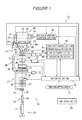
Figure 1 is a schematic diagram and a block diagram showing a general configuration of a winder unit provided in an automatic winder according to an embodiment of the present invention. -
Figure 2 is a perspective view showing how a yarn is traversed in a traverse device. -
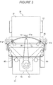
Figure 3 is a front view showing positions of a traverse guide that are included in the traverse device and used for an origin setting operation. -
Figure 4 is a flowchart showing control performed when yarn winding is performed after the power of the automatic winder is turned on. - Preferred embodiments of the present invention will be described below with reference to the drawings.
- A winder unit (yarn winding unit) 10 shown in
Figure 1 winds ayarn 20 unwound from ayarn supplying bobbin 21, around ayarn winding bobbin 22 while traversing theyarn 20. Thewinder unit 10 thus forms apackage 30 of a predetermined length and a predetermined shape. - An automatic winder (yarn winding apparatus) according to the present embodiment includes a frame and a plurality of
winder units 10 arranged on the frame in a line. The automatic winder also includes a frame control device (not shown in the drawings) located on the frame at one end of the arrangement of thewinder units 10 in the direction of the arrangement. Aframe power switch 81 is provided at an appropriate position of the frame for turning on and off the power of the automatic winder. - Each of the
winder units 10 includes a winding unitmain body 16 and aunit control section 50. - The winding unit
main body 16 includes aballoon controller 12, atension applying device 13, a splicer device 14 (yarn splicing device), and a clearer 15 arranged in this order in a yarn traveling path between ayarn supplying section 24 and acontact roller 29; theballoon controller 12 is located closest to theyarn supplying bobbin 21. - The
yarn supplying section 24 is provided at the bottom of the winding unitmain body 16 to feed a yarn toward theyarn winding bobbin 22. Theyarn supplying section 24 can hold theyarn supplying bobbin 21, which has been conveyed by a bobbin conveying system (not shown in the drawings), at a prescribed position. Instead of a configuration in which theyarn supplying bobbin 21 is conveyed by the bobbin conveying system, theyarn supplying bobbin 21 may be fed from a magazine type supply system provided in the winding unitmain body 16. - The
balloon controller 12 includes a regulatingmember 40 that is movable in a vertical direction. The regulatingmember 40 can cover a core tube of theyarn supplying bobbin 21 set on theyarn supplying section 24. Theballoon controller 12 lowers the regulatingmember 40 in conjunction with unwinding of theyarn 20 from theyarn supplying bobbin 21. Theballoon controller 12 thus assists in unwinding theyarn 20 from theyarn supplying bobbin 21. The regulatingmember 40 makes contact with a balloon formed above theyarn supplying bobbin 21 by the rotation and centrifugal force of theyarn 20 unwound from theyarn supplying bobbin 21. The regulatingmember 40 thus applies an appropriate tension to the balloon to assist in unwinding theyarn 20. A sensor (not shown in the drawings) is provided in the vicinity of the regulatingmember 40 to detect a chase portion of theyarn supplying bobbin 21. When the sensor detects that the chase portion is lowering, the regulatingmember 40 can be lowered in conjunction with the lowering of the chase portion by an air cylinder (not shown in the drawings). - The
tension applying device 13 applies a predetermined tension to the travelingyarn 20. Thetension applying device 13 may be of, for example, a gate type in whichmovable comb teeth 37 are arranged with respect to fixedcomb teeth 36. Themovable comb teeth 37 may be moved by, for example, arotary solenoid 38 so that themovable comb teeth 37 is engaged or released with respect to the fixedcomb teeth 36. Thetension applying device 13 applies a given tension to theyarn 20 being wound, to allow the quality of apackage 30 to be improved. Instead of the gate type, thetension applying device 13 may be of, for example, a disc type. - When for example, the
yarn 20 is cut as a result of a detection of a yarn defect by the clearer 15 or theyarn 20 is broken during unwinding of theyarn 20 from theyarn supplying bobbin 21, thesplicer device 14 splices a lower yarn on theyarn supplying bobbin 21 side and an upper yarn on thepackage 30 side. Such a yarn splicing device, which splices the upper yarn and the lower yarn, may be mechanical or may use a fluid such as compressed air. - The clearer 15 includes a
clearer head 49 and ananalyzer 52. A sensor (not shown in the drawings) is provided in theclearer head 49 of the clearer 15, to detect the thickness of theyarn 20. Theanalyzer 52 processes a yarn thickness signal from the sensor. The clearer 15 monitors the yarn thickness signal from the sensor to detect a yarn defect such as a slub. Acutter 39 is provided in the vicinity of theclearer head 49 to cut theyarn 20 immediately after the clearer 15 detects the yarn defect. - A lower-
yarn guide pipe 25 is provided below thesplicer device 14 to catch a lower yarn on theyarn supplying bobbin 21 side to guide the lower yarn to thesplicer device 14. An upper-yarn guide pipe 26 is provided above thesplicer device 14 to catch an upper yarn on thepackage 30 side to guide the upper yarn to thesplicer device 14. The lower-yarn guide pipe 25 is pivotally movable around ashaft 33. The upper-yarn guide pipe 26 is pivotally movable around ashaft 35. Asuction port 32 is formed at a tip of the lower-yarn guide pipe 25. Asuction mouth 34 is formed at a tip of the upper-yarn guide pipe 26. - A blower box (not shown in the drawings) as a negative pressure source is connected to the lower-
yarn guide pipe 25 and the upper-yarn guide pipe 26, respectively, via appropriate pipes. This allows thesuction port 32 and thesuction mouth 34 to generate suction flows to suck and catch yarn ends of the upper yarn and the lower yarn. - The winding unit
main body 16 includes acradle 23, an armtype traverse device 27, and acontact roller 29. Thecradle 23 removably supports the yarn winding bobbin 22 (paper tube, core tube, or the like). Thetraverse device 27 traverses theyarn 20. Thecontact roller 29 can make contact with a peripheral surface of theyarn winding bobbin 22 or a peripheral surface of thepackage 30 to rotate in conjunction with theyarn winding bobbin 22 or thepackage 30. - The
cradle 23 is pivotally movable around apivotal shaft 48. Thecradle 23 pivotally moves to absorb an increase in the diameter of a yarn layer formed by winding theyarn 20 around theyarn winding bobbin 22. - A
package driving motor 41 is attached to a portion of thecradle 23 where theyarn winding bobbin 22 is provided. Thepackage driving motor 41 rotationally drives theyarn winding bobbin 22 to wind theyarn 20 into thepackage 30. When theyarn winding bobbin 22 is supported by thecradle 23, a motor shaft of thepackage driving motor 41 is coupled to theyarn winding bobbin 22 so as not to be rotatable relative to the yarn winding bobbin 22 (the rotational driving is based on what is called a direct drive scheme). Operation of thepackage driving motor 41 is controlled by the package drivingcontrol section 42. The package drivingcontrol section 42 receives an operation signal from aunit control section 50 and controls thepackage driving motor 41 to operate and stop. - A
package rotation sensor 43 is attached to thecradle 23. Thepackage rotation sensor 43 detects rotation of theyarn winding bobbin 22 held by the cradle 23 (rotation of ayarn layer 31 formed on the yarn winding bobbin 22). A rotation detection signal for theyarn winding bobbin 22 is transmitted from thepackage rotation sensor 43 to the package drivingcontrol section 42 and theunit control section 50. Moreover, the rotation detection signal is input to atraverse control section 46 described below. - An
angle sensor 44 is attached to thepivotal shaft 48 to detect the angle (pivotal angle) of thecradle 23. Theangle sensor 44 is, for example, a rotary encoder. Theangle sensor 44 transmits an angular signal corresponding to the angle of thecradle 23, to theunit control section 50. The angle of thecradle 23 varies as winding progresses to thicken thepackage 30. Thus, by detecting the pivotal angle of thecradle 23 by theangle sensor 44, the diameter of the yarn layer of thepackage 30 can be detected. Theunit control section 50 calculates the diameter of the yarn layer of thepackage 30 based on the angular signal received from theangle sensor 44. The package yarn layer diameter calculated by theunit control section 50 is transmitted to the package drivingcontrol section 42 and thetraverse control section 46. Thetraverse control section 46 controls thetraverse device 27 according to the calculated package yarn layer diameter. Accordingly, theyarn 20 can be properly traversed. - The
traverse device 27 includes anelongate arm member 28, a hook-shaped traverse guide (traverse yarn guide) 11, and a traverse guide driving motor (traverse yarn guide driving section) 45. Thearm member 28 is turnable around a support shaft. Thetraverse guide 11 is formed at a tip of thearm member 28. The traverseguide driving motor 45 drives thearm member 28. The traverseguide driving motor 45 is a servo motor. The traverseguide driving motor 45 reciprocates thearm member 28 as shown by an arrow inFigure 1 to traverse theyarn 20. - In the present embodiment, as shown in
Figure 1 , thepackage driving motor 41 and the traverseguide driving motor 45 are separately provided. Theyarn winding bobbin 22 and thetraverse guide 11 are separately and independently driven (controlled). Thus, theyarn 20 can be wound around theyarn winding bobbin 22 while flexibly controlling the traversing of theyarn 20. - Next, the configuration of the
traverse device 27 will be described in detail with reference toFigure 2 . Thetraverse device 27 includes ahousing 54. A housing of the traverseguide driving motor 45 is fixed inside thehousing 54. Anoutput shaft 55 of the traverseguide driving motor 45 projects out from thehousing 54. A base end of thearm member 28 is fixed to a tip portion of theoutput shaft 55. - The
housing 54 is attached to an appropriate position of the winding unitmain body 16 via fixing means (not shown in the drawings).Support arms 56 are attached to thehousing 54. Thesupport arms 56 rotatably support thecontact roller 29. - The
traverse device 27 includesstoppers 65 arranged close to respective ends of a traverse stroke of thearm member 28. The twostoppers 65 are cylindrical and are composed of an elastic body such as rubber. Each of thestoppers 65 is fixed to thehousing 54. Thestoppers 65 are arranged opposite each other across the traverse range of thearm member 28 in a manner that respective side portions of thearm member 28 can make contact with thestoppers 65. - Operation of the traverse
guide driving motor 45 is controlled by thetraverse control section 46 shown inFigure 1 . Thetraverse control section 46 receives a signal from theunit control section 50 and controls the traverseguide driving motor 45 to operate and stop. - The
traverse device 27 includes a traverseguide position sensor 47 such as a rotary encoder. Thetraverse device 27 allows the traverseguide position sensor 47 to detect a turning position of the arm member 28 (or the position of the traverse guide 11). Thetraverse device 27 can thus transmit a position signal to thetraverse control section 46. - In this configuration, for example, when the
arm member 28 starts to move pivotally beyond the normal stroke range for a certain reason such as a defect in the traverseguide driving motor 45, thestopper 65 can come into contact with thearm member 28 to prevent the pivotal movement. - The
stopper 65 serves as a reference member for determining the position of a reference point (reference position) for traversing of theyarn 20 by thetraverse guide 11. That is, in the present embodiment, as shown inFigure 3 , the traverseguide position sensor 47 acquires aposition 11a of thetraverse guide 11 obtained when thearm member 28 comes into contact with one of thestoppers 65, and aposition 11b of thetraverse guide 11 obtained when thearm member 28 comes into contact with theother stopper 65. Then, an intermediate point between the two positions is determined to be a reference point 11o for traversing. - In the present embodiment, the
traverse guide 11 is driven so as to achieve a predetermined traverse stroke TS with the reference point 11o as a traverse center. The yarn winding apparatus according to the present embodiment communicates various pieces of control information such as the current position of thetraverse guide 11 based on the reference point 11o as a control origin. That is, the determination of the reference point 11o also determines the position of the control origin. Thus, in the description below, the operation of determining the reference point 11o may be referred to as "origin setting". - The
traverse control section 46 shown inFigure 1 is configured as a microcomputer and includes a central processing unit (CPU), a read only memory (ROM), and a random access memory (RAM). In thetraverse control section 46, the above-described hardware and control programs stored in the ROM constitute an origin calculating section (reference position determining section) 61, an origin storage section (reference position storage section) 62, and a motor control section (control section) 66. - In the origin setting operation, the
origin calculating section 61 calculates the control origin (reference point or reference position) of thetraverse guide 11 based on values detected by the traverseguide position sensor 47 when thearm member 28 is making contact with the respective twostoppers 65. Theorigin storage section 62 stores the control origin calculated by theorigin calculating section 61, in an appropriate memory. Themotor control section 66 calculates a target position for thetraverse guide 11 based on predetermined parameters and various pieces of control information. Themotor control section 66 transmits the calculated target position to the traverseguide driving motor 45 to reciprocate thetraverse guide 11. To calculate the target position for thetraverse guide 11, themotor control section 66 refers to the position of the control origin stored in theorigin storage section 62. - Next, the
unit control section 50 will be described. Theunit control section 50 is configured as a microcomputer and includes a CPU, a RAM, a ROM, and an input and output (I/0) port. Programs for controlling appropriate sections of the winding unitmain body 16 are stored in the ROM. - The arrangements of the winding unit
main body 16 are connected to the I/0 port so as to communicate control information with one another. The frame control device provided in the automatic winder includes an origin re-setting switch (re-determination instructing section) 75. By operating theorigin re-setting switch 75, an operator can instruct re-setting of the control origin of thetraverse device 27. - The origin
re-setting switch 75 is electrically connected to theunit control section 50, and an origin re-setting signal can be transmitted to theunit control section 50. The origin re-setting signal is transferred from theunit control section 50 to thetraverse control section 46. - Next, a control of the
traverse guide 11 according to the present embodiment will be described with reference toFigure 4 . - First, the operator operates the
frame power switch 81 to turn on the power of the automatic winder (step S101). Then, the frame control device starts operating and controllably allows power to be fed from the frame to each of thewinder units 10. As a result, theunit control section 50, the package drivingcontrol section 42, thetraverse control section 46, and the like start operating. - Once the
traverse control section 46 starts operating, the origin setting operation is immediately performed (step S102). Specifically, thetraverse control section 46 drives the traverseguide driving motor 45 to move thearm member 28 to one side. The traverseguide position sensor 47 then acquires the position (position 11a shown inFigure 3 ) of thetraverse guide 11 obtained when thearm member 28 comes into contact with thestopper 65 and can no longer move. Then, thetraverse control section 46 moves thearm member 28 to the other side. The traverseguide position sensor 47 then acquires the position (position 11b) of thetraverse guide 11 obtained when thearm member 28 comes into contact with theopposite stopper 65. Theorigin calculating section 61 calculates the position of a central point between the two acquiredpositions origin calculating section 61 determines the calculated position to be the control origin (reference point 11o). The thus determined control point is stored in theorigin storage section 62. - Then, the
motor control section 66 of thetraverse control section 46 drives the traverseguide driving motor 45 to move thetraverse guide 11 to a standby position (step S103). The standby position is set slightly outside the traverse stroke of the traversing of theyarn 20 by thetraverse guide 11 during the normal winding. - Under such a state, the
unit control section 50 stands by until a yarn splicing operation as a preliminary step for the winding operation becomes ready to be started (step S104). Further, the state in which the "yarn splicing operation becomes ready to be started" is a state in which theyarn supplying bobbin 21 is appropriately set in theyarn supplying section 24 with no defect occurring in the various devices such as thepackage driving motor 41 and the traverseguide driving motor 45. - Upon determining in step S104 that yarn splicing is enabled, the
unit control section 50 controls thesplicer device 14 to perform the yarn splicing operation (step S105). Theunit control section 50 stands by until the yarn splicing operation is completed (step S106). - In the yarn splicing operation, the upper-
yarn guide pipe 26 moves pivotally upward to suck and catch theyarn 20 of thepackage 30 side (upper yarn). The upper-yarn guide pipe 26 then guides the upper yarn to thesplicer device 14. - In this case, the
traverse guide 11 has already moved to the standby position. - Thus, the
traverse guide 11 is unlikely to interfere with the upper yarn being guided to thesplicer device 14. Consequently, the yarn splicing operation is smoothly carried out. Concurrently with the above-described guiding, the lower-yarn guide pipe 25 catches and draws out theyarn 20 of theyarn supplying bobbin 21 side (lower yarn). The lower-yarn guide pipe 25 thus guides the lower yarn to thesplicer device 14, which then splices the upper yarn and the lower yarn. - After the yarn splicing operation is completed as described above, the
traverse control section 46 controls themotor control section 66 to control the traverseguide driving motor 45 to immediately move thetraverse guide 11 to the origin position (step S107). Theunit control section 50 controls the package drivingcontrol section 42 to rotationally drive thepackage driving motor 41. Theunit control section 50 also controls thetraverse control section 46 to reciprocatingly drive the traverseguide driving motor 45. These driving operations allow the winding operation to be performed to wind theyarn 20 into thepackage 30 while traversing the yarn 20 (step S108). In the winding operation, the position of the control origin stored in theorigin storage section 62 is referred by themotor control section 66. Based on the referred position, the traverseguide driving motor 45 is controlled. - During the yarn winding operation, the
unit control section 50 controls the clearer 15 to monitor, whether or not yarn breakage has occurred (step S109). The term "yarn brakeage" as used herein also includes cutting of the vicinity of a yarn defect in theyarn 20 by thecutter 39 as a result of a detection of the yarn defect by the clearer 15. Upon determining that yarn breakage has occurred, theunit control section 50 transmits an appropriate signal to the package drivingcontrol section 42 to suspend the winding of the yarn 20 (step S110). Then, the process returns to step S103. - Upon determining in step S109 that no yarn breakage has occurred, the
unit control section 50 determines whether or not thepackage 30 is full (step S111). In this processing, theunit control section 50 determines whether or not the length over which the yarn has been wound since the start of winding of the yarn around the emptyyarn winding bobbin 22 has reached a predetermined length. If thepackage 30 is not full, the process returns to step S108 and the winding operation is continued. - Upon determining in step S111 that the
package 30 is full, theunit control section 50 controls an automatic doffing device (not shown in the drawings) to perform a doffing operation (step S112). The doffing operation removes thefull package 30 from thecradle 23 and sets a new emptyyarn winding bobbin 22 to thecradle 23. - After the doffing operation is completed, the
unit control section 50 determines whether or not theorigin re-setting switch 75 has been operated (step S113). If theorigin re-setting switch 75 has been operated, the process returns to step S102. Thetraverse control section 46 then performs the above-described origin setting operation based on a corresponding signal from theunit control section 50. Thus, theorigin calculating section 61 calculates a new control origin, which is then stored in theorigin storage section 62. If theorigin re-setting switch 75 has not been operated, the origin setting operation is not performed. Thereafter, in either case, the process proceeds to step S103 and the subsequent steps. Thesplicer device 14 performs the yarn splicing operation. Theyarn 20 starts to be wound around the newyarn winding bobbin 22. - With the control according to the above-described flow, the
yarn 20 is wound around the emptyyarn winding bobbin 22 to form thepackage 30, while the clearer 15 removes a yarn defect from theyarn 20, which is then spliced by thesplicer device 14. After formation of thepackage 30 is completed, thepackage 30 is doffed, and theyarn 20 is wound around a newyarn winding bobbin 22. As a result, thepackage 30 of a predetermined length can be formed one after another. - With the control according to the present embodiment, if yarn breakage occurs during the winding of the
yarn 20 around theyarn winding bobbin 22 and the winding is stopped in step S110, it is only necessary to perform the yarn splicing operation and then to resume the winding (steps S103 to S108). Thus, the origin setting operation as described in step S102 is not necessary to be performed again. That is, after theyarn 20 starts to be wound around the emptyyarn winding bobbin 22 and before thepackage 30 becomes full, the reference point 11o determined during the origin setting operation (step S102) performed before winding start is continuously applied without being changed during the winding, to control thetraverse guide 11. This control allows a possible deviation in the control position of thetraverse guide 11 to be avoided. Accordingly, apackage 30 of a favorable shape can be formed. Furthermore, the number of times the origin setting operation is performed is reduced, enabling a corresponding reduction in the period of time during which the winding operation is suspended. The efficiency with which thewinder unit 10 produces thepackage 30 can be improved. - In the present embodiment, even when the
package 30 becomes full and the doffing operation is performed, the origin setting operation is performed only if theorigin re-setting switch 75 is operated. That is, the position of the reference point 11o which has been determined by the origin setting operation performed for the first time after power-on, is consistently applied to control thetraverse guide 11 throughout the winding operation of a plurality ofpackage 30. Thus, the number of times the origin setting operations is performed can further be reduced. This enables a further increase in the efficiency with which thewinder unit 10 produces thepackage 30. - However, the origin setting operation is particularly preferably performed if for example, the origin setting has not been carried out for a relatively long period. In this case, the operator operates the
origin resetting switch 75 to instruct the origin to be re-set. Then, during the doffing operation, thetraverse control section 46 controls the origin setting to be carried out. For thesubsequent packages 30, thetraverse guide 11 is controlled based on the newly determined control origin. Thus, even if theorigin re-setting switch 75 is operated, the origin setting is not carried out during the winding of theyarn 20 but during the doffing operation. As a result, a possible step on an end surface of thepackage 30 can be prevented, and apackage 30 of an acceptable shape can be obtained. - As described above, the automatic winder according to the present embodiment includes the
package driving motor 41, thetraverse guide 11, the traverseguide driving motor 45, theorigin calculating section 61, theorigin storage section 62, and themotor control section 66. Thepackage driving motor 41 rotationally drives theyarn winding bobbin 22 around which theyarn 20 is wound to form thepackage 30. Thetraverse guide 11 engages with and traverses theyarn 20. - The traverse
guide driving motor 45 reciprocatingly drives thetraverse guide 11. Theorigin calculating section 61 determines the reference origin serving as the reference for driving of thetraverse guide 11. Theorigin storage section 62 stores the reference position determined by the referenceposition determining section 61. Themotor control section 66 controls the traverseguide driving motor 45 by continuously applying, from beginning to end of winding of apackage 30, the control origin determined by theorigin calculating section 61 and stored in theorigin storage section 62 before the yarn starts to be wound into thepackage 30. - This configuration can prevent a possible situation in which the origin setting operation is performed during the winding of one
package 30 and the control origin of thetraverse guide 11 is changed. Accordingly, the control position of thetraverse guide 11 is prevented from being deviated, and a step is prevented from being formed on the winding package. Furthermore, the number of times the origin setting operations to be performed is reduced, enabling a reduction in the period of time during which a winding operation is suspended. As a result, the productivity with which the automatic winder produces thepackage 30 can be effectively inhibited from decreasing. - In the automatic winder according to the present embodiment, until formation of a plurality of the
packages 30 is completed, themotor control section 66 controls the traverseguide driving motor 45 by continuously applying, from beginning to end of winding, the control origin which has been determined by theorigin calculating section 61 and stored in theorigin storage section 62 before the yarn starts to be wound into thefirst package 30. - This arrangement enables a further reduction in the number of times the origin setting operations to be performed. As a result, the productivity with which the automatic winder produces the
package 30 can further be improved. - In the automatic winder according to the present embodiment, until formation of a plurality of the
packages 30 is completed, themotor control section 66 controls the traverseguide driving motor 45 by continuously applying the control origin which has been determined by theorigin calculating section 61 and stored in theorigin storage section 62 after a power of the automatic winder is turned on and before the yarn starts to be wound into thefirst package 30. - Thus, the origin setting operation (in principle) needs to be performed only once immediately after the power of the automatic winder is turned on. This further improves the productivity with which the automatic winder produces the
package 30. - The automatic winder according to the present embodiment further includes the
origin re-setting switch 75 that is operated to allow theorigin calculating section 61 to re-determine the control origin. When theorigin resetting switch 75 is operated, theorigin calculating section 61 re-determines the control origin, and theorigin storage section 62 re-stores the new control origin. Themotor control section 66 thereafter controls the traverseguide driving motor 45 by continuously applying the new reference position until formation of a plurality of thepackages 30 is completed. - Thus, if the control origin specially needs to be re-determined, the origin setting can be carried out by operating the
origin re-setting switch 75. Then, thetraverse guide 11 can be driven based on the new control origin. Consequently, the control origin can be flexibly determined, allowing both the quality of thepackage 30 and the productivity to be improved. - Preferred embodiments of the present invention have been described. The above-described configuration can be varied, for example, as described below.
- The
traverse device 27 has only to be configured to be able to control the reciprocating driving of thetraverse guide 11 independently of rotation of theyarn winding bobbin 22. For example, the traverse device may be configured such that a belt is driven by a motor to reciprocate the traverse guide. - Instead of the configuration in which the
yarn winding bobbin 22 is driven directly by thepackage driving motor 41, a configuration may be used in which thecontact roller 29 is driven by a motor so that thepackage 30 side rotates in conjunction with rotation of thecontact roller 29. - The traverse
guide driving motor 45 may be composed of, instead of the servo motor, for example, a voice coil motor or a step motor. - The traverse
guide position sensor 47 has only to be configured to be able to detect the position of thetraverse guide 11, thearm member 28, or the output shaft or a rotor of the traverseguide driving motor 45. For example, the rotary encoder adopted in the above-described embodiment may be replaced with, for example, a resolver. - In the above-described embodiment, the standby position of the
traverse guide 11 is set slightly outside the traverse stroke. However, the standby position may be set at one end of the traverse stroke. Alternatively, the standby position may be set at a position where thearm member 28 comes into contact with one of thestoppers 65. - The origin setting operation may be performed at any timing before the
yarn 20 starts to be wound around the emptyyarn winding bobbin 22. For example, the origin setting operation may be performed, for example, after completion of the yarn splicing operation rather than immediately before thetraverse guide 11 is moved to the standby position as shown inFigure 4 . - The origin setting operation may be performed every time the doffing operation is completed for one
package 30. In this case, theorigin re-setting switch 75 may be omitted. - In the above-described embodiment, the control origin (reference point) of the
traverse guide 11 is set to be the central point of the traverse stroke. However, a position at one end of the traverse stroke may be determined to be the control origin (reference point). - The
origin calculating section 61, theorigin storage section 62, and themotor control section 66 may be provided on theunit control section 50 side rather than in thetraverse control section 46. - In the above-described embodiment, the
arm member 28 is drivingly controlled so as to come into contact first with theleft stopper 65 of thetraverse device 27 and then contact with theright stopper 65 inFigure 3 . However, the order in which thearm member 28 comes into contact with thestoppers 65 may be such that thearm member 28 comes into contact first with theright stopper 65 and then with theleft stopper 65 inFigure 3 . - The arrangements of the
traverse device 27 and thetraverse control section 46 are applicable not only to the automatic winder but also to, for example, a spinning machine serving as a yarn winding machine. - While the present invention has been described with respect to preferred embodiments thereof, it will be apparent to those skilled in the art that the disclosed invention may be modified in numerous ways and may assume many embodiments other than those specifically set out and described above. Accordingly, it is intended by the appended claims to cover all modifications of the present invention that fall within the scope of the invention.
Claims (4)
- A yarn winding apparatus comprising:a yarn winding bobbin driving device (41) that rotationally drives a yarn winding bobbin around which a yarn is wound to form a package;a traverse yarn guide (11) that engages with and traverses the yarn;a traverse yarn guide driving device (45) that reciprocates the traverse yarn guide (11) ;a reference position determining section (61) that determines a reference position serving as a reference for driving of the traverse yarn guide (11) ;a reference position storage section (62) that stores the reference position determined by the reference position determining section (61); anda control section (46, 50) that controls the traverse yarn guide driving device (45) by continuously applying, from beginning to end of winding of the package, the reference position that has been determined by the reference position determining section (61) and stored in the reference position storage section (62) before the yarn starts to be wound into the package.
- The yarn winding apparatus according to Claim 1, characterized in that until formation of a plurality of packages is completed, the control section (46, 50) controls the traverse yarn guide driving device (45) by continuously applying the reference position that has been determined by the reference position determining section (61) and stored in the reference position storage section (62) before the yarn starts to be wound into a first package.
- The yarn winding apparatus according to Claim 2, characterized in that until formation of a plurality of packages is completed, the control section (46, 50) controls the traverse yarn guide driving device (45) by continuously applying the reference position that has been determined by the reference position determining section (61) and stored in the reference position storage section (62) after power is turned on and before the yarn starts to be wound into the first package.
- The yarn winding apparatus according to Claim 2 or 3, characterized by further comprising a re-determination instructing section (75) that is operated to re-determine the reference position by the reference position determining section (61), and
characterized in that when the re-determination instructing section (75) is operated, the reference position determining section (61) re-determines the reference position, and the reference position storage section (62) re-stores the new reference position, and
the control section (46, 50) thereafter controls the traverse yarn guide driving device (45) by continuously applying the new reference position until formation of a plurality of packages is completed.
Applications Claiming Priority (1)
| Application Number | Priority Date | Filing Date | Title |
|---|---|---|---|
| JP2008075399A JP2009227414A (en) | 2008-03-24 | 2008-03-24 | Yarn winder |
Publications (2)
| Publication Number | Publication Date |
|---|---|
| EP2105398A2 true EP2105398A2 (en) | 2009-09-30 |
| EP2105398A3 EP2105398A3 (en) | 2010-10-06 |
Family
ID=40673884
Family Applications (1)
| Application Number | Title | Priority Date | Filing Date |
|---|---|---|---|
| EP09154184A Withdrawn EP2105398A3 (en) | 2008-03-24 | 2009-03-03 | Yarn Winding Apparatus |
Country Status (3)
| Country | Link |
|---|---|
| EP (1) | EP2105398A3 (en) |
| JP (1) | JP2009227414A (en) |
| CN (1) | CN101544319B (en) |
Cited By (4)
| Publication number | Priority date | Publication date | Assignee | Title |
|---|---|---|---|---|
| CN102190206A (en) * | 2010-03-17 | 2011-09-21 | 村田机械株式会社 | Yarn winding machine |
| EP2366651A3 (en) * | 2010-03-17 | 2012-02-15 | Murata Machinery, Ltd. | Yarn winding device |
| EP2036847A3 (en) * | 2007-09-12 | 2012-05-09 | Oerlikon Textile GmbH & Co. KG | Method and device for positioning a finger yarn guide of a textile machine for creating cross-wound spools |
| DE102014215599B4 (en) | 2013-08-13 | 2022-05-25 | Murata Machinery, Ltd. | YARN WINDING MACHINE AND YARN WINDING PROCESS |
Families Citing this family (10)
| Publication number | Priority date | Publication date | Assignee | Title |
|---|---|---|---|---|
| CN101837907A (en) * | 2010-03-15 | 2010-09-22 | 青岛宏大纺织机械有限责任公司 | Traverse yarn guide device of bobbin winder |
| JP2012218922A (en) * | 2011-04-13 | 2012-11-12 | Murata Machinery Ltd | Yarn winding apparatus and yarn withdrawal method |
| JP2014223980A (en) * | 2013-05-16 | 2014-12-04 | 村田機械株式会社 | Yarn winding apparatus and yarn winding method |
| JP6491747B2 (en) | 2015-09-30 | 2019-03-27 | デューク・ユニヴァーシティ | Contrast agent for magnetic resonance imaging |
| CN109081175A (en) * | 2018-09-04 | 2018-12-25 | 青岛宏大纺织机械有限责任公司 | A kind of automatic winder and its control method of swing rod guide |
| EP3865442B1 (en) * | 2018-10-09 | 2024-10-23 | TMT Machinery, Inc. | Yarn winder and package production method |
| CN109338525A (en) * | 2018-10-18 | 2019-02-15 | 苏州宸浩纺织科技有限公司 | Integrated type yarn storing and twisting mechanism is used in a kind of weaving |
| CN111056371A (en) * | 2020-01-14 | 2020-04-24 | 曹超铨 | Uniform yarn guide device of winder reciprocating along with winding process |
| CN111056381B (en) * | 2020-01-21 | 2024-12-06 | 青岛宏大纺织机械有限责任公司 | A kind of yarn guiding device and yarn guiding method of automatic winding machine |
| CN115520724B (en) * | 2022-09-29 | 2023-11-07 | 浙江康立自控科技有限公司 | Deviation rectifying control system and method for winding device of silk winder |
Citations (1)
| Publication number | Priority date | Publication date | Assignee | Title |
|---|---|---|---|---|
| JP2004189359A (en) | 2002-12-09 | 2004-07-08 | Murata Mach Ltd | Method for determining origin of traverse guide of traverse device |
Family Cites Families (6)
| Publication number | Priority date | Publication date | Assignee | Title |
|---|---|---|---|---|
| TR200000187T2 (en) * | 1997-07-26 | 2000-11-21 | Barmag Ag | Method and arrangement for crossing a weaving thread |
| CH693094A5 (en) * | 1998-10-28 | 2003-02-28 | Rieter Ag Maschf | Traversing unit. |
| EP1125877A1 (en) * | 2000-02-17 | 2001-08-22 | Schärer Schweiter Mettler AG | Winding head and its use |
| DE102005001094A1 (en) * | 2005-01-08 | 2006-07-20 | Saurer Gmbh & Co. Kg | Method and device for operating a workstation of a textile machine producing cross-wound bobbins |
| DE102005002409A1 (en) * | 2005-01-19 | 2006-07-27 | Saurer Gmbh & Co. Kg | Method and device for determining the zero position of an oscillatable thread guide |
| DE102005029150B3 (en) * | 2005-06-23 | 2006-11-09 | Georg Sahm Gmbh & Co. Kg | Automatic bobbin winder, with a reciprocating yarn guide, has a compressed air stream directed at the guide path to detect the spatial position of a low mass yarn guide |
-
2008
- 2008-03-24 JP JP2008075399A patent/JP2009227414A/en active Pending
-
2009
- 2009-02-18 CN CN2009100064549A patent/CN101544319B/en active Active
- 2009-03-03 EP EP09154184A patent/EP2105398A3/en not_active Withdrawn
Patent Citations (1)
| Publication number | Priority date | Publication date | Assignee | Title |
|---|---|---|---|---|
| JP2004189359A (en) | 2002-12-09 | 2004-07-08 | Murata Mach Ltd | Method for determining origin of traverse guide of traverse device |
Cited By (6)
| Publication number | Priority date | Publication date | Assignee | Title |
|---|---|---|---|---|
| EP2036847A3 (en) * | 2007-09-12 | 2012-05-09 | Oerlikon Textile GmbH & Co. KG | Method and device for positioning a finger yarn guide of a textile machine for creating cross-wound spools |
| CN102190206A (en) * | 2010-03-17 | 2011-09-21 | 村田机械株式会社 | Yarn winding machine |
| EP2366650A3 (en) * | 2010-03-17 | 2012-02-15 | Murata Machinery, Ltd. | Yarn winding machine |
| EP2366651A3 (en) * | 2010-03-17 | 2012-02-15 | Murata Machinery, Ltd. | Yarn winding device |
| CN102190206B (en) * | 2010-03-17 | 2015-04-01 | 村田机械株式会社 | Yarn winding machine |
| DE102014215599B4 (en) | 2013-08-13 | 2022-05-25 | Murata Machinery, Ltd. | YARN WINDING MACHINE AND YARN WINDING PROCESS |
Also Published As
| Publication number | Publication date |
|---|---|
| JP2009227414A (en) | 2009-10-08 |
| CN101544319A (en) | 2009-09-30 |
| EP2105398A3 (en) | 2010-10-06 |
| CN101544319B (en) | 2012-08-22 |
Similar Documents
| Publication | Publication Date | Title |
|---|---|---|
| EP2377793B1 (en) | Yarn winding device and automatic winder | |
| JP2009227414A (en) | Yarn winder | |
| EP2687468B1 (en) | Yarn winding device and yarn winding method | |
| EP2511216B2 (en) | Yarn winding apparatus and yarn withdrawal method | |
| EP2366650B1 (en) | Yarn winding machine | |
| EP2738129B1 (en) | Yarn winding machine, and textile machine including the yarn winding machine | |
| EP2366651B1 (en) | Yarn winding device | |
| EP2105399B1 (en) | Yarn winding device and yarn winding method | |
| JP4991482B2 (en) | Method for preparing a spinning cup formed with a spinning device for the rewinding process in an automatic traverse winding device and device for carrying out the method | |
| EP2738127A2 (en) | Yarn winding machine and yarn withdrawal method | |
| JP2000238963A (en) | Method of operating one working unit of a textile machine for winding a twill package | |
| EP2366649A2 (en) | Yarn winding machine | |
| EP2530040B1 (en) | Yarn winding device | |
| EP2078691B1 (en) | Kink preventing device and automatic winder comprising the same | |
| EP2738128B1 (en) | Yarn winding machine | |
| EP2669229B1 (en) | Package discharging device and yarn winding machine | |
| CN109422136B (en) | Yarn winding machine | |
| EP2700601A2 (en) | Yarn winding unit and yarn winding machine | |
| JP2007223779A (en) | Thread winding machine | |
| CN111132918B (en) | Yarn winding machine | |
| CN104129679B (en) | Yarn winding apparatus | |
| JP2013063838A (en) | Yarn winding machine | |
| JP2010013259A (en) | Yarn-winding machine and displacement control method of cradle | |
| JP2014223980A (en) | Yarn winding apparatus and yarn winding method | |
| CN112110281B (en) | Yarn winding device and method for forming package yarn |
Legal Events
| Date | Code | Title | Description |
|---|---|---|---|
| PUAI | Public reference made under article 153(3) epc to a published international application that has entered the european phase |
Free format text: ORIGINAL CODE: 0009012 |
|
| AK | Designated contracting states |
Kind code of ref document: A2 Designated state(s): AT BE BG CH CY CZ DE DK EE ES FI FR GB GR HR HU IE IS IT LI LT LU LV MC MK MT NL NO PL PT RO SE SI SK TR |
|
| AX | Request for extension of the european patent |
Extension state: AL BA RS |
|
| PUAL | Search report despatched |
Free format text: ORIGINAL CODE: 0009013 |
|
| AK | Designated contracting states |
Kind code of ref document: A3 Designated state(s): AT BE BG CH CY CZ DE DK EE ES FI FR GB GR HR HU IE IS IT LI LT LU LV MC MK MT NL NO PL PT RO SE SI SK TR |
|
| AX | Request for extension of the european patent |
Extension state: AL BA RS |
|
| 17P | Request for examination filed |
Effective date: 20110405 |
|
| AKX | Designation fees paid |
Designated state(s): AT BE BG CH CY CZ DE DK EE ES FI FR GB GR HR HU IE IS IT LI LT LU LV MC MK MT NL NO PL PT RO SE SI SK TR |
|
| 17Q | First examination report despatched |
Effective date: 20110629 |
|
| STAA | Information on the status of an ep patent application or granted ep patent |
Free format text: STATUS: THE APPLICATION HAS BEEN WITHDRAWN |
|
| 18W | Application withdrawn |
Effective date: 20120203 |