EP2669229B1 - Package discharging device and yarn winding machine - Google Patents
Package discharging device and yarn winding machine Download PDFInfo
- Publication number
- EP2669229B1 EP2669229B1 EP13165532.6A EP13165532A EP2669229B1 EP 2669229 B1 EP2669229 B1 EP 2669229B1 EP 13165532 A EP13165532 A EP 13165532A EP 2669229 B1 EP2669229 B1 EP 2669229B1
- Authority
- EP
- European Patent Office
- Prior art keywords
- package
- section
- contact
- yarn
- winding
- Prior art date
- Legal status (The legal status is an assumption and is not a legal conclusion. Google has not performed a legal analysis and makes no representation as to the accuracy of the status listed.)
- Not-in-force
Links
Images


Classifications
-
- B—PERFORMING OPERATIONS; TRANSPORTING
- B65—CONVEYING; PACKING; STORING; HANDLING THIN OR FILAMENTARY MATERIAL
- B65H—HANDLING THIN OR FILAMENTARY MATERIAL, e.g. SHEETS, WEBS, CABLES
- B65H67/00—Replacing or removing cores, receptacles, or completed packages at paying-out, winding, or depositing stations
- B65H67/04—Arrangements for removing completed take-up packages and or replacing by cores, formers, or empty receptacles at winding or depositing stations; Transferring material between adjacent full and empty take-up elements
- B65H67/0405—Arrangements for removing completed take-up packages or for loading an empty core
- B65H67/0411—Arrangements for removing completed take-up packages or for loading an empty core for removing completed take-up packages
-
- B—PERFORMING OPERATIONS; TRANSPORTING
- B65—CONVEYING; PACKING; STORING; HANDLING THIN OR FILAMENTARY MATERIAL
- B65H—HANDLING THIN OR FILAMENTARY MATERIAL, e.g. SHEETS, WEBS, CABLES
- B65H54/00—Winding, coiling, or depositing filamentary material
- B65H54/02—Winding and traversing material on to reels, bobbins, tubes, or like package cores or formers
- B65H54/22—Automatic winding machines, i.e. machines with servicing units for automatically performing end-finding, interconnecting of successive lengths of material, controlling and fault-detecting of the running material and replacing or removing of full or empty cores
- B65H54/26—Automatic winding machines, i.e. machines with servicing units for automatically performing end-finding, interconnecting of successive lengths of material, controlling and fault-detecting of the running material and replacing or removing of full or empty cores having one or more servicing units moving along a plurality of fixed winding units
-
- B—PERFORMING OPERATIONS; TRANSPORTING
- B65—CONVEYING; PACKING; STORING; HANDLING THIN OR FILAMENTARY MATERIAL
- B65H—HANDLING THIN OR FILAMENTARY MATERIAL, e.g. SHEETS, WEBS, CABLES
- B65H2701/00—Handled material; Storage means
- B65H2701/30—Handled filamentary material
- B65H2701/31—Textiles threads or artificial strands of filaments
Definitions
- the present invention relates to a package discharging device and a yarn winding machine.
- a yarn winding machine forms a package by winding a yarn around a bobbin (winding tube).
- the package is held by a cradle of the yarn winding machine.
- Various methods and devices are available for removing and discharging the package held by the cradle.
- a package is pushed by a rod into an axial direction of a bobbin and thereby removed from the cradle.
- a cradle is released to move a package temporarily onto a winding drum, and subsequently, a package pushing-out member arranged in a doffing apparatus protrudes so that the package is guided by a guiding member and moved finally to a transport conveyor.
- a pushing-out lever is arranged to push a package in a rear direction, and a resin collar is attached to the tip of the pushing-out lever so as not to damage the yarn layer surface of the package.
- EP 2 441 720 A2 relates to a doffer which includes support members and a bobbin guiding cylinder.
- the support members support a package formed by winding a spun yarn on a bobbin.
- the bobbin guiding cylinder drives the support members to convey a fully wound package supported by the support members from a position (first position) of the package at which the support members receive the package that is fully wound to a position of a package receiving section (second position).
- a package discharging device which discharges a package including at least a winding tube held by a holding section has the features of claim 1.
- a yarn winding machine includes the above package discharging device; and a winding device.
- the winding device has the holding section and winds a yarn around the winding tube held by the holding section. With this yarn winding machine, the package can be reliably discharged from the winding device, while reducing the impact on the package.
- upstream and downstream are used with respect to upstream and downstream of a running direction of a yarn that is being wound.
- the automatic winder 1 includes multiple winder units (winding units) 10 that are aligned side-by-side, a doffing apparatus 80, and a main controller 90. As seen in the drawing, a single doffing apparatus 80 and a single main controller 90 are arranged for the multiple winder units 10. A package discharging device 100 is arranged in the doffing apparatus 80.
- Each of the winder units 10 unwinds a yarn 20 from a supply bobbin 21 and winds the yarn 20 around a winding bobbin (winding tube) 22 (see FIG. 2 ) while traversing the yarn 20 to form a package 30.
- the package 30 includes at least the winding bobbin 22.
- the "package 30" indicates both an empty winding bobbin 22 itself around which the yarn 20 is yet to be wound and a winding bobbin 22 around which the yarn 20 has been wound.
- an outer periphery 30a of the package 30 also means an outer periphery 22c of the winding bobbin 22 (see FIGS. 3 to 5 ).
- winding bobbins 22 and packages 30 of various sizes and shapes can be used.
- the package 30 can be a cheese package shaped into a cylinder, or a cone package shaped into a truncated cone.
- the doffing apparatus 80 moves to a position corresponding to the winder unit 10, discharges the fully wound package 30, and supplies an empty bobbin (i.e., an empty winding tube).
- the doffing apparatus 80 discharges the package 30 by using the package discharging device 100.
- the discharged package 30 is placed onto a package placing section 79 that is arranged near a cradle 23, which holds the winding bobbin 22, on a side opposite to the doffing apparatus 80 (see FIG. 7C ).
- the doffing apparatus 80 suitably discharges not only fully wound packages 30 but also empty winding bobbins 22 and/or partially wound packages 30.
- the main controller 90 includes a control section 91 and a display section 92.
- An operator inputs predetermined setting values and selects a suitable controlling method to be used by the control section 91 so that the control section 91 makes appropriate settings for each of the winder units 10.
- the display section 92 displays a state of each winder unit 10 winding the yarn 20, details of problems that arise, and the like.
- Each of the winder units 10 includes a winding unit main body 16 and a unit controller 50.
- the unit controller 50 includes, for example, a central processing unit (CPU), a random access memory (RAM), a read only memory (ROM), an input-output (I/O) port, and a communication port.
- the ROM stores therein computer programs for controlling the structural components of the winding unit main body 16.
- the structural components of the winding unit main body 16 and the main controller 90 are connected to the I/O port and the communication port so that communications of control information and the like can be established.
- the unit controller 50 can thereby control the operation of the components of the winding unit main body 16.
- a yarn unwinding assisting device 12 In the yarn running path between the supply bobbin 21 and a contact roller (touch roller) 29 in the winding unit main body 16, a yarn unwinding assisting device 12, a tension applying device 13, a splicer (yarn joining device) 14, and a clearer 15 are arranged in this order from the supply bobbin 21 side.
- a yarn supplying section 11 that supplies the yarn 20 to the winding bobbin 22 is arranged in a lower portion of the winding unit main body 16.
- the yarn supplying section 11 supports the supply bobbin 21 transported by a not-shown bobbin transport system, at a predetermined position.
- the yarn unwinding assisting device 12 assists the unwinding of the yarn 20 from the supply bobbin 21 by moving downward a regulating member 40 that caps the inner tube of the supply bobbin 21 as the yarn 20 is unwound from the supply bobbin 21.
- the regulating member 40 comes into contact with a balloon formed on the upper portion of the supply bobbin 21 due to rotational and centrifugal force of the yarn 20 unwound from the supply bobbin 21, controls the balloon to be of an appropriate size, and thereby assists the unwinding of the yarn 20.
- a not-shown sensor that detects a chase portion of the supply bobbin 21 is arranged near the regulating member 40. When this sensor detects the chase portion descending, the yarn unwinding assisting device 12 can move the regulating member 40 downward in accordance with the chase portion, for example, by an action of a not-shown air cylinder.
- the tension applying device 13 applies a predetermined tension to the running yarn 20.
- a gate-type tension applying device in which movable comb teeth are arranged to correspond to fixed comb teeth, can be employed.
- the movable comb teeth can be swung by a rotary solenoid so that the two sets of comb teeth can be engaged with or released from each other.
- a disk-type tension applying device can be employed as the tension applying device 13.
- the splicer 14 joins a lower yarn from the supply bobbin 21 and an upper yarn from the package 30.
- a yarn joining device that joins the upper yarn and the lower yarn a yarn joining device of mechanical type or of a type that uses fluid such as compressed air, or the like can be used.
- the clearer 15 includes a clearer head 49, in which a not-shown sensor that detects thickness of the yarn 20 is arranged, and an analyzer 52 that processes a yarn thickness signal received from this sensor.
- the clearer 15 monitors this yarn thickness signal received from the sensor, and thereby detects a yarn defect such as a slub.
- the yarn defect detected by the clearer 15 can be an irregularity in the thickness of the yarn 20 or a foreign material contained in the yarn 20.
- a cutter 39 is arranged near the clearer head 49 so that the yarn 20 can be cut immediately when the clearer 15 detects a yarn defect.
- a lower yarn catching section 125 that catches a yarn end from the supply bobbin 21 and guides it to the splicer 14 is arranged below the splicer 14, and an upper yarn catching section 26 that catches a yarn end from the package 30 and guides it to the splicer 14 is arranged above the splicer 14.
- the lower yarn catching section 125 includes a lower yarn pipe arm 33 and a lower yarn suction vent 32 formed at a free end of the lower yarn pipe arm 33.
- the upper yarn catching section 26 includes an upper yarn pipe arm 36 and an upper yarn suction vent (yarn end catching section) 35 formed at a free end of the upper yarn pipe arm 36.
- the lower yarn pipe arm 33 and the upper yarn pipe arm 36 can pivot around shafts 34 and 37, respectively.
- a suitable negative pressure source (not shown) is connected to each of the lower yarn pipe arm 33 and the upper yarn pipe arm 36.
- the negative pressure source generates a suction airflow through the lower yarn suction vent 32 and the upper yarn suction vent 35 so that the ends of the upper yarn and the lower yarn can be sucked and caught.
- the winding unit main body 16 includes a winding device 75 that winds the yarn 20 around the winding bobbin 22.
- the winding device 75 includes the cradle (holding section) 23 that detachably supports the winding bobbin 22, and the contact roller 29 that can rotate in contact with the outer periphery 30a of the package 30.
- the winding device 75 includes an arm-type traversing device 70 that is arranged near the cradle 23 and that traverses the yarn 20.
- the winding device 75 winds the yarn 20 into the package 30 while traversing the yarn 20 by the traversing device 70.
- a guide plate 28 is arranged slightly upstream with respect to the traversing position, and guides the upstream yarn 20 to the traversing position.
- a ceramic traversing support 27 is arranged further upstream with respect to the guide plate 28.
- the traversing device 70 includes a traverse driving motor 76 that is formed by a servomotor or the like.
- a traverse controller 78 controls the operation of the traverse driving motor 76.
- the traverse driving motor 76 operates to drive a traverse arm so that the traversing device 70 traverses the yarn 20 in a winding width direction of the package 30 (the direction indicated by an arrow in FIG. 2 ) with the traversing support 27 serving as the center.
- the traverse controller 78 is a piece of hardware that is a dedicated microprocessor or the like. Upon receiving a signal from the unit controller 50, the traverse controller 78 controls and stops the operation of the traverse driving motor 76. Besides the servomotor, various motors such as a step motor and a voice coil motor can be employed as the traverse driving motor 76.
- the cradle 23 includes a cradle main body 24 that sandwiches and supports the winding bobbin 22 at a larger-diameter side end portion 22a and a smaller-diameter side end portion 22b of the winding bobbin 22.
- the cradle main body 24 can swing around a swing shaft 48. When the diameter of a yarn layer of the yarn 20 wound around the winding bobbin 22 increases, this increase can be absorbed by the swinging of the cradle 23.
- the cradle main body 24 includes a first cradle arm 24a that faces the larger-diameter side end portion 22a of the winding bobbin 22, a second cradle arm 24b that faces the smaller-diameter side end portion 22b of the winding bobbin 22, and a cradle lever 24c that is attached to the first cradle arm 24a and that extends towards the doffing apparatus 80.
- the tight-fitting section 25 is shaped into a truncated cone tapered toward the winding bobbin 22. Because of the tight-fitting section 25 that is shaped into a truncated cone, the tight-fitting section 25 is engaged into the winding bobbin 22. This makes the tight-fitting section 25 stop where the inner diameter of the winding bobbin 22 agrees with the outer diameter of the tight-fitting section 25 so that the tight-fitting section 25 is tightly fitted to the winding bobbin 22, even if there are some variations in the diameters of the winding bobbins 22. It is not necessary that the tight-fitting section 25 be made of polyurethane rubber but can be made of other materials such as silicon rubber.
- the tight-fitting section 25 can be formed of any material.
- the tight-fitting section 25 can be shaped substantially into a cylinder.
- a package driving motor (package driving section) 41 which is a servomotor, is arranged on the first cradle arm 24a of the cradle main body 24.
- the package driving motor 41 drives to rotate the winding bobbin 22 to wind the yarn 20 around the winding bobbin 22 (package 30).
- the package driving motor 41 can rotate the winding bobbin 22 (package 30) in the winding direction, and also in the reverse direction.
- a shaft of the package driving motor 41 is coupled to the winding bobbin 22 in such a manner that the package driving motor 41 and the winding bobbin 22 cannot rotate relatively with each other (i.e., direct drive system).
- the force of the cradle 23 holding the package 30 (winding bobbin 22) can be enhanced.
- a winder unit 10 that performs winding at high speed such holding force needs to be enhanced.
- the operation of the package driving motor 41 is controlled by a package driving controller 42.
- the package driving controller 42 Upon receiving an operation signal from the unit controller 50, the package driving controller 42 controls and stops the operation of the package driving motor 41.
- the package driving motor 41 need not be a servomotor, but various motors such as a step motor and an induction motor can be employed as the package driving motor 41.
- An angle sensor 44 that detects an angle of the cradle 23 is arranged on the swing shaft 48.
- This angle sensor 44 can be, for example, a rotary encoder.
- the angle sensor 44 sends an angle signal corresponding to the angle of the cradle 23 to the unit controller 50.
- the swing angle of the cradle 23 changes accompanying an increase in the wound diameter of the package 30. Accordingly, the diameter of the package 30 can be detected based on the detected swing angle of the cradle 23 with the angle sensor 44.
- a suitable structure that can detect the diameter of the package 30, such as one that uses a Hall IC or an absolute encoder, can be used in place of the angle sensor 44.
- the doffing apparatus 80 includes a main frame 85, a yarn pulling-out arm 86, a cradle opener (operating section) 87, a bobbin supplying section 88, and the package discharging device 100.
- the doffing apparatus 80 activates the cradle opener 87 and the package discharging device 100 to discharge the package 30, and activates the bobbin supplying section 88 to supply an empty winding bobbin 22.
- the doffing apparatus 80 activates the yarn pulling-out arm 86 to catch the yarn 20 from the supply bobbin 21 and guide the yarn 20 to the empty winding bobbin 22.
- a rail 83 is arranged along an aligning direction of the winder units 10 (horizontal direction in FIG. 1 ) above the winding unit main bodies 16.
- the main frame 85 of the doffing apparatus 80 moves along the rail 83.
- Positioning blocks 82 are arranged along the rail 83 at positions corresponding to the winder units 10.
- the main frame 85 of the doffing apparatus 80 includes a not-shown flapper mechanism that can swing between a position at which the flapper mechanism is engaged with a positioning block 82 and a position at which it is disengaged. By engaging the flapper mechanism with the positioning block 82, the doffing apparatus 80 determines an appropriate position immediately above the target winder unit 10 and stops there.
- the position at which the doffing apparatus 80 stops is not limited to a position immediately above a winder unit 10.
- the doffing apparatus 80 can stop at a position other than the one immediately above the winder unit 10, as long as an intended operation can be performed onto the winder unit 10.
- the yarn pulling-out arm 86 has a structure in which rod-like members of different diameters are coaxially nested inside one another so that the yarn pulling-out arm 86 can extend and contract in a telescoping manner.
- the yarn pulling-out arm 86 is an air cylinder in which extension and contraction can be driven by compressed air supplied from a not-shown compressed air source.
- the yarn pulling-out arm 86 is arranged on the doffing apparatus 80 pointing toward the winding unit main body 16.
- a yarn catching section 81 is arranged at a free end (lower end) of the yarn pulling-out arm 86. The yarn catching section 81 moves in directions of moving closer to and moving away from the winder unit 10 as the yarn pulling-out arm 86 swings.
- the bobbin supplying section 88 picks up an empty winding bobbin 22 from a not-shown bobbin stocker within the doffing apparatus 80.
- the bobbin supplying section 88 is arranged swingably with respect to a shaft 89.
- the doffing apparatus 80 drives the bobbin supplying section 88 to swing between a position of picking up the winding bobbin 22 from the bobbin stocker and a position of setting the winding bobbin 22 onto the cradle 23.
- the cradle opener 87 operates and releases the first cradle arm 24a when the cradle opener 87 swings while being engaged with the cradle lever 24c of the cradle 23 (see FIG. 3 ).
- the first cradle arm 24a is released, the first cradle arm 24a is moved in the direction away from the second cradle arm 24b with respect to the position of holding the winding bobbin 22.
- the package 30 may not be detached from the cradle main body 24 simply by releasing the first cradle arm 24a (see FIG. 7A ).
- the package discharging device 100 serves effectively in such a case, to reliably remove the package 30.
- the package discharging device 100 includes a first roller (package contact section) 108 formed of resin and that can come into contact with the outer periphery 30a of the package 30, and an air cylinder (first moving section) 101 that moves the first roller 108 in a movement direction D1.
- first roller package contact section
- air cylinder first moving section
- the main frame 85 includes a pair of side panels: a first side panel 85a and a second side panel.
- the first side panel 85a is positioned closer to the main controller 90 than the second side panel is.
- An air cylinder 101 is fixed to the first side panel 85a.
- the air cylinder 101 includes a cylinder 102 fixed to the first side panel 85a and a rod 103 that extends and contracts in the movement direction D1 by the action of compressed air supplied from the not-shown compressed air source.
- An L-shaped bracket 106 is fixed onto the inner surface of the first side panel 85a that faces the second side panel.
- the bracket 106 includes a fixation panel 106a that is fixed onto the first side panel 85a and a supporting panel 106b that is continued from the fixation panel 106a and that faces the package 30.
- the tip end of the cylinder 102 is fixed to the supporting panel 106b.
- the rod 103 extends and contracts between the supporting panel 106b and the winding bobbin 22 in the movement direction D1 at predetermined strokes. The strokes of the rod 103 are determined such that the first roller 108 reaches the winding bobbin 22 held by the cradle 23 when the rod 103 is most extended.
- the fixation panel 106a is fixed to the first side panel 85a.
- the supporting panel 106b makes an acute angle with respect to the fixation panel 106a.
- the cylinder 102 of the air cylinder 101 is fixed substantially perpendicularly to the supporting panel 106b. Consequently, the movement direction D1 of the rod 103 is angled with respect to a horizontal plane and also to a vertical plane.
- the rod 103 can extend toward the package 30 in a direction that forms an acute angle with respect to the axial line of the winding bobbin 22.
- a metallic base 104 is fixed to the tip end of the rod 103.
- a metallic arm 107 is attached to the base 104 with a shaft 110 arranged therebetween.
- the arm 107 includes two arm portions, a first arm portion 107a and a second arm portion 107b, that extend in two different directions from the position of the shaft 110.
- the first arm portion 107a and the second arm portion 107b form an obtuse angle with each other.
- the first arm portion 107a and the second arm portion 107b pivot together around the shaft 110 within a predetermined range.
- the cylindrical first roller 108 is attached to the first arm portion 107a at its free end with a shaft 111 arranged therebetween.
- the first roller 108 can rotate around a shaft line L1 of the shaft 111 with respect to the first arm portion 107a.
- the shaft line L1 runs orthogonal to the movement direction D1.
- the shaft line L1 does not always have to run orthogonal to the movement direction D1.
- the shaft line L1 can run along another direction crossing the movement direction D1. With the rod 103 of the air cylinder 101 extending in the movement direction D1, a periphery 108a of the first roller 108 comes into contact with the outer periphery 30a of the package 30 (or the outer periphery 22c of the winding bobbin 22).
- the first roller 108 comes into contact with the package 30 at substantially the center of the package 30 in the shaft direction of the package 30.
- the contact position of the first roller 108 is not limited to substantially the center of the package 30 in the axial direction, however.
- the contact position of the first roller 108 can be closer to the first cradle arm 24a or closer to the second cradle arm 24b in the axial direction of the package 30. If the package 30 is, for example, a cylindrical cheese package, the package 30 moves (rolls) straight to the package placing section 79 regardless of the position in the axial direction at which the first roller 108 is in contact.
- the first roller 108 can be brought into contact on the smaller diameter side (closer to the second cradle arm 24b) so that the package 30 is prevented from obliquely rolling off.
- the contact position of the first roller 108 can be suitably adjusted in accordance with the shape or fixation position of the bracket 106 or with the fixation position or angle of the air cylinder 101.
- a cylindrical second roller 109 formed of resin is attached to the free end of the second arm portion 107b with a shaft 112 arranged therebetween (see FIG. 6B ).
- the second roller 109 rotates around a shaft line L2 of the shaft 112 with respect to the second arm portion 107b.
- the shaft line L2 is parallel to the shaft line L1.
- the package discharging device 100 includes a coil spring (pressure adjusting section) 120 that adjusts a pressing force applied to the package 30 when the first roller 108 comes into contact with the outer periphery 30a of the package 30 (see FIGS. 6A and 6B ).
- the coil spring 120 is arranged between the first roller 108 and the air cylinder 101. More specifically, the coil spring 120 is a twisted coil spring wound around the shaft 110, with its one end fixed to the base 104 and the other end fixed to the arm 107.
- the coil spring 120 urges the arm 107 in a direction of tilting the first arm portion 107a forward (counterclockwise in FIG. 5 ).
- the coil spring 120 urges the first roller 108 toward the package 30 via the first arm portion 107a when the first roller 108 comes into contact with the outer periphery 30a of the package 30.
- the coil spring 120 pushes, with its resilience, the first roller 108 against the package 30.
- the spring constant of the coil spring 120 can be suitably determined in accordance with the target package 30 or the winding bobbin 22 that is to be discharged.
- the air cylinder 101 moves the first roller 108 to a contact position at which the first roller 108 comes into contact with the package 30 held by the cradle 23, or to a receded position at which the first roller 108 is receded from the package 30 held by the cradle 23.
- two contact positions of the first roller 108 are shown; a contact position P1 on the outer periphery 30a of the package 30 having a certain diameter, and a contact position P2 on the empty winding bobbin 22.
- the pressing force applied to the package 30 can be adjusted by the pressing force adjusting function of the coil spring 120.
- the coil spring 120 adjusts discharging energy (pushing-out force) required when discharging the package 30. In other words, the coil spring 120 absorbs variation in the diameter of the package 30.
- the second roller 109 comes into contact with the bottom of the supporting panel 106b.
- the arm 107 stands up against the urging force of the coil spring 120 (i.e., the arm 107 pivots clockwise around the shaft 110 as shown in FIG. 5 ).
- the first roller 108 moves to a standby position P3.
- the first roller 108 and the arm 107 are positioned inside the edge of the first side panel 85a and housed in the main frame 85.
- the supporting panel 106b, the arm 107, and the second roller 109 form a second moving section 121 that causes the first roller 108 currently staying at the receded position to move to a standby position, which is further receded from the package 30.
- the unit controller 50 of the winder unit 10 detects a package 30 that is to be doffed
- the unit controller 50 stops the package driving motor 41 of the winder unit 10 (see FIG. 7A ).
- the unit controller 50 outputs to the main controller 90 a signal indicating that the to-be-doffed package 30 has been detected.
- the doffing apparatus 80 stops in front of the winder unit 10, and releases the first cradle arm 24a by engaging the cradle opener 87 with the cradle lever 24c.
- the main controller 90 operates the air cylinder 101 of the package discharging device 100 to bring the first roller 108 into contact with the outer periphery 30a of the package 30 (see FIG. 7B ).
- the coil spring 120 adjusts the pressing force applied to the package 30 and thereby reduces the impact upon the package 30.
- the air cylinder 101 does not have to be operated at the same timing as the releasing of the first cradle arm 24a.
- the air cylinder 101 can be operated after the first cradle arm 24a is released.
- the tight-fitting section 25 is engaged into and tightly fitted to the winding bobbin 22 so that the package 30 is still held by the first cradle arm 24a in a cantilevered manner (the package 30 may come off the tight-fitting section 25 under its own weight as soon as the first cradle arm 24a is released, for example, if the package 30 has a large diameter or if the winding density of the yarn 20 is high).
- the package 30 discharged by the package discharging device 100 is placed onto the package placing section 79. The discharging operation of the package 30 performed by the package discharging device 100 is thereby completed (see FIG. 7C ).
- the package 30 placed onto the package placing section 79 is collected manually by the operator.
- a conveyor belt can be employed for the package placing section 79 so that the package 30 can be automatically transported to and collected at a predetermined position.
- the winding bobbin 22 of the package 30 is held by the cradle 23.
- the first roller 108 is moved by the air cylinder 101 such that the first roller 108 is brought into contact with the outer periphery 30a of the package 30.
- the coil spring 120 adjusts the pressing force applied to the package 30 when the first roller 108 is in contact with the outer periphery 30a of the package 30. Because of the adjustment of the pressing force, the first roller 108 is prevented from pressing the package 30 too strongly as the diameter of the package 30 increases. The impact on the package 30 can be thereby reduced, regardless of the diameter of the package 30.
- the impact on the package 30 can be reduced by a simple structure.
- the first roller 108 is brought into contact with the outer periphery 30a of the package 30 under a substantially constant pressing force that is caused by the urging force (resilient force) of the coil spring 120.
- the impact on the package 30 can be thereby reliably and readily reduced. If the air cylinder 101 moves the first roller 108 towards the winding bobbin 22 further than the outer periphery 30a of the package 30, the first roller 108 is pushed back due to a reaction force from the outer periphery 30a of the package 30 against the urging force of the coil spring 120. Consequently, the pressing force is prevented from being applied excessively to the package 30.
- the air cylinder 101 moves the first roller 108 to a contact position (e.g., the contact position P1 or P2) at which the first roller 108 comes into contact with the package 30 held by the cradle 23 and to the receded position at which the first roller 108 is receded from the package 30 held by the cradle 23. Consequently, when the first roller 108 does not need to be in contact with the package 30, the air cylinder 101 can move the first roller 108 to recede at the receded position.
- a contact position e.g., the contact position P1 or P2
- the first roller 108 With the air cylinder 101 that moves the first roller 108, the first roller 108 can be brought to the contact position or to the receded position by a simple structure.
- the second moving section 121 moves the first roller 108, which is currently staying at the receded position, further back to the standby position P3. Therefore, interference or contact of the first roller 108 with other members can be reliably avoided. Especially for the doffing apparatus 80 that moves along the rail 83, contact with the cradle lever 24c of the cradle 23 in the winder unit 10 can be avoided (see FIG. 4 ).
- the coil spring 120 is arranged between the first roller 108 and the air cylinder 101, and therefore the air cylinder 101 does not exert its force directly onto the first roller 108. Consequently, even if the air cylinder 101 has a large force, the impact on the package 30 can be reduced.
- the periphery 108a of the first roller 108 is brought into contact with the outer periphery 30a of the package 30.
- the package 30 therefore can be reliably discharged even if the position of the first roller 108 relative to the package 30 has been changed.
- the first roller 108 when rotating, is prevented from rubbing its periphery 108a against the outer periphery 30a of the package 30. Consequently, damage to the package 30 can be minimized.
- the rubber tight-fitting section 25 is tightly fitted to the larger-diameter side end portion 22a of the winding bobbin 22 so that the power of the cradle main body 24 holding the winding bobbin 22 can be enhanced.
- the package discharging device 100 that can reliably discharge the package 30. Especially when the package 30 has a small diameter or when the package 30 has a large diameter but a low winding density (i.e., when soft-wound), the package 30 would not easily come off the cradle main body 24. In such situations, the package discharging device 100 comes to serve effectively.
- the package discharging device 100 starts operating. This further facilitates the discharging of the package 30.
- FIG. 8 is a cross-section taken parallel to a side face of a doffing apparatus including a package discharging device according to a second embodiment.
- a package discharging device 100A of a doffing apparatus 80A shown in FIG. 8 is different from the package discharging device 100 shown in FIG. 4 in that a cylindrical contact member 130 that faces the package 30 is used in place of the first roller 108 and also that a linear scale 129 that helps in adjusting the stroke length of the rod 103 is arranged on the air cylinder 101.
- the contact member 130 is fixed to the tip end of the rod 103.
- a rubber member can be attached to the tip surface of the contact member 130 (the surface that comes in contact with the package 30).
- the arm 107, the first roller 108, the second roller 109, the coil spring 120, or the like is not arranged in the package discharging device 100A.
- a package diameter obtaining section is arranged in a winder unit according to the second embodiment.
- the following modes can be employed for the package diameter obtaining section.
- the package diameter obtaining section according to a first mode is the analyzer 52 (see FIG. 2 ).
- the analyzer 52 obtains the package diameter based on the total length of the yarn 20 wound into the package 30 and the winding speed and yarn type (e.g., thickness) of the yarn 20.
- the package diameter obtaining section according to a second mode is the angle sensor 44 discussed above.
- the angle sensor 44 obtains the package diameter by detecting the swing angle of the cradle 23.
- the package diameter obtaining section is the analyzer 52.
- the analyzer 52 measures the time elapsed from the start of the winding of the yarn 20 and obtains the package diameter from the measured elapsed time. If the winding speed and the yarn type (e.g., the thickness of the yarn 20) are known, the package diameter can be empirically obtained based on the time elapsed from the start of the winding of the yarn 20. By storing beforehand a relationship between the elapsed time from the start of the winding and the package diameter in the analyzer 52, the package diameter can be obtained based on the measured elapsed time. When the winding is suspended due to yarn cut and/or yarn joining, the measurement of the elapsed time from the start of the winding is also suspended.
- the package diameter obtaining section according to a fourth mode is the analyzer 52.
- the analyzer 52 calculates the package diameter based on a running speed of the yarn 20 detected by a yarn running speed sensor. More specifically, a traversing angle is calculated from the running speed and a traversing speed of the yarn 20. Subsequently, a peripheral speed of the package 30 is obtained based on the traversing angle and the running speed of the yarn 20. The package diameter is calculated based on a rotational speed and the peripheral speed of the package 30.
- the unit controller 50 of the winder unit 10 sends the data of the package diameter to the doffing apparatus 80A.
- the doffing apparatus 80A adjusts, in accordance with the package diameter, the stroke length of the rod 103, or in other words a moving distance of the contact member 130 by using the linear scale 129.
- a contact position P5 on the outer periphery 30a of the package 30 having a certain diameter and a contact position P6 on the empty winding bobbin 22 are shown as examples of the contact positions of the contact member 130 in FIG. 8 .
- the air cylinder 101 functions as a pressure adjusting section 140
- the linear scale 129 functions as a moving distance adjusting section 150.
- the package discharging device 100A according to the second embodiment also reduces the impact on the package 30 regardless of the package diameter.
- the moving distance adjusting section 150 that adjusts the moving distance of the contact member 130, too long or too short movement of the contact member 130 can be avoided, and the moving distance of the contact member 130 can be suitably maintained.
- the package diameter obtaining section and the unit controller 50 adjust the moving distance of the contact member 130 in accordance with the diameter of the package 30.
- the contact member 130 can thereby be suitably brought into contact with the package 30.
- the unit controller 50 can be provided with a function of the package diameter obtaining section.
- the twisted coil spring 120 has been explained as the pressure adjusting section 140; however, the pressure adjusting section 140 is not limited thereto.
- the pressure adjusting section 140 for example, a compression coil spring can be arranged along the movement direction of the package contact section and used for urging the package contact section against the package 30.
- the first embodiment in which the pressing power adjusting function is realized by the coil spring 120, the first roller 108, and the like, and the second embodiment, in which the pressing power adjusting function is realized by the package diameter obtaining section, the linear scale 129, the unit controller 50, and the like, can be combined.
- the moving distance of the package contact section does not always have to be adjusted based on the package diameter obtained by the package diameter obtaining section.
- the moving distance of the package contact section can be adjusted based on the type or winding density of the yarn 20. For example, the strokes of the air cylinder 101 can be set larger as the package has a lower winding density.
- the doffing apparatus 80 or 80A that performs the operations of supplying an empty winding bobbin 22 and of catching and guiding the yarn 20 has been explained in the embodiments.
- the doffing apparatus 80 or 80A can be dedicated to the operation of discharging the package 30 only.
- the first moving section formed of the air cylinder 101 has been explained in the present embodiments; however, the first moving section is not limited to the air cylinder 101, and a different extending/contracting structure can be employed.
- a moving section can have a bellows, lattice, or sliding structure.
- the shape, size, or material of the package contact section can be suitably modified.
- the material is not limited to resin, but can be rubber.
- the tight-fitting section 25 does not have to be a truncated cone.
- the tight-fitting section 25 can be a flat plate so that it can be pressed against an end of the winding bobbin 22.
- the package discharging device 100 does not have to be arranged in the doffing apparatus 80 or 80A, but can be arranged as an independent device.
- the package discharging device 100 can be arranged for each of the winder units 10.
- Multiple doffing apparatuses 80 can be arranged to correspond to the number of winder units 10 of the automatic winder 1.
- the yarn winding machine can include a winding device that has a traversing drum.
- the yarn winding machine can include an air-spinning apparatus.
- the yarn winding machine can be an open-end spinning frame or the like, or any yarn winding machine that can wind a yarn around a package.
- the package diameter obtaining section of the winder unit according to the second embodiment (at least one of the first to fourth modes) can be applied to the winder unit according to the first embodiment.
- the linear scale 129 can be arranged on the air cylinder 101 so that the stroke length of the rod 103 can be adjusted.
- the package 30 can be forcibly pulled in the axial direction and discharged.
- a package discharging device which discharges a package including at least a winding tube held by a holding section, includes a package contact section capable of coming into contact with an outer periphery of the package; a first moving section that causes the package contact section to move so as to come into contact with the outer periphery of the package; and a pressure adjusting section that adjusts a pressing force applied to the package when the package contact section is in contact with the outer periphery of the package.
- a package here means an empty winding tube itself around which no yarn has been wound, and also a winding tube around which a yarn has been wound.
- the pressure adjusting section is preferably a spring. Consequently, the package discharging device that reduces the impact on the package can be realized with a simple structure.
- the spring preferably urges the package contact section toward the package when the package contact section comes into contact with the outer periphery of the package such that the package contact section is pressed against the package by a resilient force of the spring.
- the package contact section stays in contact with the outer periphery of the package under substantially a constant pressing force. The impact on the package is therefore reliably and readily reduced. If the first moving section moves the package contact section toward the winding tube further out of the outer periphery of the package, the package contact section is pushed back by a reaction force from the outer periphery of the package against the urging force of the spring. This prevents an excessive pressing force from being exerted on the package.
- the first moving section preferably moves the package contact section to a contact position at which the package contact section is in contact with the package held by the holding section, and a receded position at which the package contact section is receded from the package held by the holding section.
- the first moving section is preferably an air cylinder. Consequently, the first moving section that causes the package contact section to move to the contact position and to the receded position can be realized with a simple structure.
- the package discharging device preferably further includes a moving distance adjusting section that adjusts a moving distance of the package contact section.
- a moving distance adjusting section that adjusts a moving distance of the package contact section.
- the package discharging device preferably further includes a second moving section that moves the package contact section to a standby position receded from the package further than the receded position.
- the package contact section can be reliably prevented from interfering with or coming into contact with other members.
- the pressure adjusting section is arranged between the package contact section and the first moving section.
- the package contact section is preferably a roller that rotates around a shaft line crossing a movement direction of the package contact section and has an outer periphery that comes into contact with the outer periphery of the package.
- the outer periphery of the roller comes into contact with the outer periphery of the package. Consequently, even if the position of the package contact section relative to the package changes, the package can be reliably discharged.
- the roller which can rotate, the outer periphery of the roller is prevented from rubbing against the outer periphery of the package, and therefore damage to the package can be minimized.
- a yarn winding machine includes the above package discharging device; and a winding device.
- the winding device has the holding section and winds a yarn around the winding tube held by the holding section. With this yarn winding machine, the package can be reliably discharged from the winding device, with the impact reduced on the package.
- the holding section of the winding device preferably includes a cradle main body that sandwiches the winding tube at two end potions of the winding tube; and a tight-fitting section that is arranged on the cradle main body and tightly fitted to at least one of the end potions of the winding tube.
- the cradle main body With the rubber tight-fitting section that is tightly fitted to at least one end of the winding tube, the cradle main body can support the winding tube with a high holding force.
- the package discharging device of the present invention that can reliably discharge the package comes to be especially effective.
- the yarn winding machine preferably further includes an operating section that operates the holding section of the winding device, wherein the package discharging device starts operating when the operating section operates the holding section.
- the package discharging device starts operating when the holding section is operated, and therefore discharging of the package can be further facilitated.
- the yarn winding machine preferably further includes a diameter obtaining section that obtains a diameter of the package; and a control section that controls the first moving section of the package discharging device and thereby adjusts the moving distance of the package contact section in accordance with the diameter of the package obtained by the diameter obtaining section.
- the impact on the package can be reduced regardless of the diameter of the package.
Description
- The present invention relates to a package discharging device and a yarn winding machine.
- A yarn winding machine forms a package by winding a yarn around a bobbin (winding tube). The package is held by a cradle of the yarn winding machine. Various methods and devices are available for removing and discharging the package held by the cradle.
- For example, in a package removing device disclosed in Japanese Utility Model Application Laid-open No.
S57-18559 S59-61161 H3-120171 - In the above conventional devices and apparatus, a large impact can be exerted upon the package when removing the package. It is known that the finished diameter of the package can vary in accordance with the length or material of the wound yarn. However, as the diameter of the package increases, the package is pressed harder by the package pushing-out member. Consequently, with the conventional technologies, it is difficult to reduce the impact exerted upon the package, regardless of the diameter of the package.
-
EP 2 441 720 A2 relates to a doffer which includes support members and a bobbin guiding cylinder. The support members support a package formed by winding a spun yarn on a bobbin. The bobbin guiding cylinder drives the support members to convey a fully wound package supported by the support members from a position (first position) of the package at which the support members receive the package that is fully wound to a position of a package receiving section (second position). - It is an object of the present invention to provide a package discharging device and a yarn winding machine that can reduce the impact on the package, regardless of the diameter of the package.
- A package discharging device according to an aspect of the present invention, which discharges a package including at least a winding tube held by a holding section has the features of claim 1.
- A yarn winding machine according to another aspect of the present invention includes the above package discharging device; and a winding device. The winding device has the holding section and winds a yarn around the winding tube held by the holding section. With this yarn winding machine, the package can be reliably discharged from the winding device, while reducing the impact on the package.
-
-
FIG. 1 is a schematic diagram of an automatic winder including winder units according to a first embodiment of the present invention; -
FIG. 2 is a schematic and block diagram of an overall structure of a winder unit; -
FIG. 3 is a plan view of an overall structure of a cradle; -
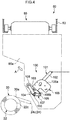
FIG. 4 is a cross-section taken parallel to a side face of a doffing apparatus including a package discharging device according to the first embodiment; -
FIG. 5 is an enlarged view of a part of the structure shown inFIG. 4 ; -
FIG. 6A is a diagram of the package discharging device viewed from a direction indicated by an arrow A shown inFIG. 4 , andFIG. 6B is a diagram of the package discharging device viewed from the package side; -
FIGS. 7A to 7C are plan views of a package in a package discharging operation; and -
FIG. 8 is a cross-section taken parallel to a side face of a doffing apparatus including a package discharging device according to a second embodiment. - Exemplary embodiments of the present invention are explained in detail below with reference to the accompanying drawings. In the explanation of the drawings, the same components are given the same numerals, and redundant explanation is omitted.
- First, an overall structure of an automatic winder (yarn winding machine) 1 according to the first embodiment is explained. Throughout this specification, "upstream" and "downstream" are used with respect to upstream and downstream of a running direction of a yarn that is being wound.
- As shown in
FIG. 1 , the automatic winder 1 includes multiple winder units (winding units) 10 that are aligned side-by-side, adoffing apparatus 80, and amain controller 90. As seen in the drawing, asingle doffing apparatus 80 and a singlemain controller 90 are arranged for themultiple winder units 10. Apackage discharging device 100 is arranged in thedoffing apparatus 80. - Each of the
winder units 10 unwinds ayarn 20 from asupply bobbin 21 and winds theyarn 20 around a winding bobbin (winding tube) 22 (seeFIG. 2 ) while traversing theyarn 20 to form apackage 30. Thepackage 30 includes at least thewinding bobbin 22. The "package 30" indicates both an empty windingbobbin 22 itself around which theyarn 20 is yet to be wound and a windingbobbin 22 around which theyarn 20 has been wound. Moreover, for example, anouter periphery 30a of thepackage 30 also means anouter periphery 22c of the winding bobbin 22 (seeFIGS. 3 to 5 ). Meanwhile, windingbobbins 22 andpackages 30 of various sizes and shapes can be used. For example, thepackage 30 can be a cheese package shaped into a cylinder, or a cone package shaped into a truncated cone. - When the
package 30 is fully wound at any of thewinder units 10, thedoffing apparatus 80 moves to a position corresponding to thewinder unit 10, discharges the fullywound package 30, and supplies an empty bobbin (i.e., an empty winding tube). Thedoffing apparatus 80 discharges thepackage 30 by using thepackage discharging device 100. The dischargedpackage 30 is placed onto apackage placing section 79 that is arranged near acradle 23, which holds thewinding bobbin 22, on a side opposite to the doffing apparatus 80 (seeFIG. 7C ). Thedoffing apparatus 80 suitably discharges not only fully woundpackages 30 but also empty windingbobbins 22 and/or partially woundpackages 30. - The
main controller 90 includes acontrol section 91 and adisplay section 92. An operator inputs predetermined setting values and selects a suitable controlling method to be used by thecontrol section 91 so that thecontrol section 91 makes appropriate settings for each of thewinder units 10. Thedisplay section 92 displays a state of eachwinder unit 10 winding theyarn 20, details of problems that arise, and the like. - A structure of a
winder unit 10 is now explained with reference toFIG. 2 . Each of thewinder units 10 includes a winding unitmain body 16 and aunit controller 50. - The
unit controller 50 includes, for example, a central processing unit (CPU), a random access memory (RAM), a read only memory (ROM), an input-output (I/O) port, and a communication port. The ROM stores therein computer programs for controlling the structural components of the winding unitmain body 16. The structural components of the winding unitmain body 16 and themain controller 90 are connected to the I/O port and the communication port so that communications of control information and the like can be established. Theunit controller 50 can thereby control the operation of the components of the winding unitmain body 16. - In the yarn running path between the
supply bobbin 21 and a contact roller (touch roller) 29 in the winding unitmain body 16, a yarnunwinding assisting device 12, atension applying device 13, a splicer (yarn joining device) 14, and a clearer 15 are arranged in this order from thesupply bobbin 21 side. - A
yarn supplying section 11 that supplies theyarn 20 to the windingbobbin 22 is arranged in a lower portion of the winding unitmain body 16. Theyarn supplying section 11 supports thesupply bobbin 21 transported by a not-shown bobbin transport system, at a predetermined position. - The yarn
unwinding assisting device 12 assists the unwinding of theyarn 20 from thesupply bobbin 21 by moving downward a regulatingmember 40 that caps the inner tube of thesupply bobbin 21 as theyarn 20 is unwound from thesupply bobbin 21. The regulatingmember 40 comes into contact with a balloon formed on the upper portion of thesupply bobbin 21 due to rotational and centrifugal force of theyarn 20 unwound from thesupply bobbin 21, controls the balloon to be of an appropriate size, and thereby assists the unwinding of theyarn 20. A not-shown sensor that detects a chase portion of thesupply bobbin 21 is arranged near the regulatingmember 40. When this sensor detects the chase portion descending, the yarnunwinding assisting device 12 can move the regulatingmember 40 downward in accordance with the chase portion, for example, by an action of a not-shown air cylinder. - The
tension applying device 13 applies a predetermined tension to the runningyarn 20. As an example of thetension applying device 13, a gate-type tension applying device, in which movable comb teeth are arranged to correspond to fixed comb teeth, can be employed. The movable comb teeth can be swung by a rotary solenoid so that the two sets of comb teeth can be engaged with or released from each other. Besides the gate-type tension applying device, a disk-type tension applying device can be employed as thetension applying device 13. - When the clearer 15 detects a yarn defect and cuts the
yarn 20, or when theyarn 20 runs out when being unwound from thesupply bobbin 21, thesplicer 14 joins a lower yarn from thesupply bobbin 21 and an upper yarn from thepackage 30. As the yarn joining device that joins the upper yarn and the lower yarn, a yarn joining device of mechanical type or of a type that uses fluid such as compressed air, or the like can be used. - The clearer 15 includes a
clearer head 49, in which a not-shown sensor that detects thickness of theyarn 20 is arranged, and ananalyzer 52 that processes a yarn thickness signal received from this sensor. The clearer 15 monitors this yarn thickness signal received from the sensor, and thereby detects a yarn defect such as a slub. The yarn defect detected by the clearer 15 can be an irregularity in the thickness of theyarn 20 or a foreign material contained in theyarn 20. Acutter 39 is arranged near theclearer head 49 so that theyarn 20 can be cut immediately when the clearer 15 detects a yarn defect. - A lower
yarn catching section 125 that catches a yarn end from thesupply bobbin 21 and guides it to thesplicer 14 is arranged below thesplicer 14, and an upperyarn catching section 26 that catches a yarn end from thepackage 30 and guides it to thesplicer 14 is arranged above thesplicer 14. The loweryarn catching section 125 includes a loweryarn pipe arm 33 and a loweryarn suction vent 32 formed at a free end of the loweryarn pipe arm 33. The upperyarn catching section 26 includes an upperyarn pipe arm 36 and an upper yarn suction vent (yarn end catching section) 35 formed at a free end of the upperyarn pipe arm 36. - The lower
yarn pipe arm 33 and the upperyarn pipe arm 36 can pivot aroundshafts yarn pipe arm 33 and the upperyarn pipe arm 36. The negative pressure source generates a suction airflow through the loweryarn suction vent 32 and the upperyarn suction vent 35 so that the ends of the upper yarn and the lower yarn can be sucked and caught. - As shown in
FIGS. 2 and3 , the winding unitmain body 16 includes a windingdevice 75 that winds theyarn 20 around the windingbobbin 22. The windingdevice 75 includes the cradle (holding section) 23 that detachably supports the windingbobbin 22, and thecontact roller 29 that can rotate in contact with theouter periphery 30a of thepackage 30. - The winding
device 75 includes an arm-type traversing device 70 that is arranged near thecradle 23 and that traverses theyarn 20. The windingdevice 75 winds theyarn 20 into thepackage 30 while traversing theyarn 20 by the traversingdevice 70. Aguide plate 28 is arranged slightly upstream with respect to the traversing position, and guides theupstream yarn 20 to the traversing position. Aceramic traversing support 27 is arranged further upstream with respect to theguide plate 28. The traversingdevice 70 includes atraverse driving motor 76 that is formed by a servomotor or the like. Atraverse controller 78 controls the operation of thetraverse driving motor 76. Thetraverse driving motor 76 operates to drive a traverse arm so that the traversingdevice 70 traverses theyarn 20 in a winding width direction of the package 30 (the direction indicated by an arrow inFIG. 2 ) with the traversingsupport 27 serving as the center. Thetraverse controller 78 is a piece of hardware that is a dedicated microprocessor or the like. Upon receiving a signal from theunit controller 50, thetraverse controller 78 controls and stops the operation of thetraverse driving motor 76. Besides the servomotor, various motors such as a step motor and a voice coil motor can be employed as thetraverse driving motor 76. - The
cradle 23 includes a cradlemain body 24 that sandwiches and supports the windingbobbin 22 at a larger-diameterside end portion 22a and a smaller-diameterside end portion 22b of the windingbobbin 22. The cradlemain body 24 can swing around aswing shaft 48. When the diameter of a yarn layer of theyarn 20 wound around the windingbobbin 22 increases, this increase can be absorbed by the swinging of thecradle 23. - The cradle
main body 24 includes afirst cradle arm 24a that faces the larger-diameterside end portion 22a of the windingbobbin 22, asecond cradle arm 24b that faces the smaller-diameterside end portion 22b of the windingbobbin 22, and acradle lever 24c that is attached to thefirst cradle arm 24a and that extends towards the doffingapparatus 80. A polyurethane tight-fittingsection 25, which is tightly fitted to the larger-diameterside end portion 22a of the windingbobbin 22 by engaging into the larger-diameterside end portion 22a, is arranged on the windingbobbin 22 side of thefirst cradle arm 24a. The tight-fittingsection 25 is shaped into a truncated cone tapered toward the windingbobbin 22. Because of the tight-fittingsection 25 that is shaped into a truncated cone, the tight-fittingsection 25 is engaged into the windingbobbin 22. This makes the tight-fittingsection 25 stop where the inner diameter of the windingbobbin 22 agrees with the outer diameter of the tight-fittingsection 25 so that the tight-fittingsection 25 is tightly fitted to the windingbobbin 22, even if there are some variations in the diameters of the windingbobbins 22. It is not necessary that the tight-fittingsection 25 be made of polyurethane rubber but can be made of other materials such as silicon rubber. In place of the rubber tight-fittingsection 25, a metallic package holding section or a package holding section of other materials can be arranged. As long as slipping would not occur between the windingbobbin 22 and the tight-fittingsection 25, the tight-fittingsection 25 can be formed of any material. The tight-fittingsection 25 can be shaped substantially into a cylinder. - A package driving motor (package driving section) 41, which is a servomotor, is arranged on the
first cradle arm 24a of the cradlemain body 24. Thepackage driving motor 41 drives to rotate the windingbobbin 22 to wind theyarn 20 around the winding bobbin 22 (package 30). Thepackage driving motor 41 can rotate the winding bobbin 22 (package 30) in the winding direction, and also in the reverse direction. - When the winding
bobbin 22 is held by thecradle 23, a shaft of thepackage driving motor 41 is coupled to the windingbobbin 22 in such a manner that thepackage driving motor 41 and the windingbobbin 22 cannot rotate relatively with each other (i.e., direct drive system). According to the present embodiment, with the tight-fittingsection 25 arranged between thefirst cradle arm 24a and the windingbobbin 22, the force of thecradle 23 holding the package 30 (winding bobbin 22) can be enhanced. Especially for awinder unit 10 that performs winding at high speed, such holding force needs to be enhanced. The operation of thepackage driving motor 41 is controlled by apackage driving controller 42. Upon receiving an operation signal from theunit controller 50, thepackage driving controller 42 controls and stops the operation of thepackage driving motor 41. Thepackage driving motor 41 need not be a servomotor, but various motors such as a step motor and an induction motor can be employed as thepackage driving motor 41. - An
angle sensor 44 that detects an angle of thecradle 23 is arranged on theswing shaft 48. Thisangle sensor 44 can be, for example, a rotary encoder. Theangle sensor 44 sends an angle signal corresponding to the angle of thecradle 23 to theunit controller 50. The swing angle of thecradle 23 changes accompanying an increase in the wound diameter of thepackage 30. Accordingly, the diameter of thepackage 30 can be detected based on the detected swing angle of thecradle 23 with theangle sensor 44. To detect the diameter of thepackage 30, a suitable structure that can detect the diameter of thepackage 30, such as one that uses a Hall IC or an absolute encoder, can be used in place of theangle sensor 44. - A structure of the doffing
apparatus 80 is explained below. As shown inFIG. 1 , the doffingapparatus 80 includes amain frame 85, a yarn pulling-outarm 86, a cradle opener (operating section) 87, abobbin supplying section 88, and thepackage discharging device 100. The doffingapparatus 80 activates thecradle opener 87 and thepackage discharging device 100 to discharge thepackage 30, and activates thebobbin supplying section 88 to supply an empty windingbobbin 22. The doffingapparatus 80 activates the yarn pulling-outarm 86 to catch theyarn 20 from thesupply bobbin 21 and guide theyarn 20 to the empty windingbobbin 22. - A
rail 83 is arranged along an aligning direction of the winder units 10 (horizontal direction inFIG. 1 ) above the winding unitmain bodies 16. Themain frame 85 of the doffingapparatus 80 moves along therail 83. Positioning blocks 82 are arranged along therail 83 at positions corresponding to thewinder units 10. Themain frame 85 of the doffingapparatus 80 includes a not-shown flapper mechanism that can swing between a position at which the flapper mechanism is engaged with apositioning block 82 and a position at which it is disengaged. By engaging the flapper mechanism with thepositioning block 82, the doffingapparatus 80 determines an appropriate position immediately above thetarget winder unit 10 and stops there. The position at which thedoffing apparatus 80 stops is not limited to a position immediately above awinder unit 10. The doffingapparatus 80 can stop at a position other than the one immediately above thewinder unit 10, as long as an intended operation can be performed onto thewinder unit 10. - The yarn pulling-out
arm 86 has a structure in which rod-like members of different diameters are coaxially nested inside one another so that the yarn pulling-outarm 86 can extend and contract in a telescoping manner. The yarn pulling-outarm 86 is an air cylinder in which extension and contraction can be driven by compressed air supplied from a not-shown compressed air source. The yarn pulling-outarm 86 is arranged on the doffingapparatus 80 pointing toward the winding unitmain body 16. Ayarn catching section 81 is arranged at a free end (lower end) of the yarn pulling-outarm 86. Theyarn catching section 81 moves in directions of moving closer to and moving away from thewinder unit 10 as the yarn pulling-outarm 86 swings. - The
bobbin supplying section 88 picks up an empty windingbobbin 22 from a not-shown bobbin stocker within the doffingapparatus 80. Thebobbin supplying section 88 is arranged swingably with respect to ashaft 89. The doffingapparatus 80 drives thebobbin supplying section 88 to swing between a position of picking up the windingbobbin 22 from the bobbin stocker and a position of setting the windingbobbin 22 onto thecradle 23. - The
cradle opener 87 operates and releases thefirst cradle arm 24a when thecradle opener 87 swings while being engaged with thecradle lever 24c of the cradle 23 (seeFIG. 3 ). When thefirst cradle arm 24a is released, thefirst cradle arm 24a is moved in the direction away from thesecond cradle arm 24b with respect to the position of holding the windingbobbin 22. According to the present embodiment, with the tight-fittingsection 25 engaged into the windingbobbin 22, thepackage 30 may not be detached from the cradlemain body 24 simply by releasing thefirst cradle arm 24a (seeFIG. 7A ). Thepackage discharging device 100 serves effectively in such a case, to reliably remove thepackage 30. - As shown in
FIGS. 4 and5 , thepackage discharging device 100 includes a first roller (package contact section) 108 formed of resin and that can come into contact with theouter periphery 30a of thepackage 30, and an air cylinder (first moving section) 101 that moves thefirst roller 108 in a movement direction D1. InFIGS. 4 and5 , the yarn pulling-outarm 86, thecradle opener 87, thebobbin supplying section 88, and the like, which have been mentioned above, have not been shown for the sake of simplicity. - The
main frame 85 includes a pair of side panels: afirst side panel 85a and a second side panel. Thefirst side panel 85a is positioned closer to themain controller 90 than the second side panel is. Anair cylinder 101 is fixed to thefirst side panel 85a. Theair cylinder 101 includes acylinder 102 fixed to thefirst side panel 85a and arod 103 that extends and contracts in the movement direction D1 by the action of compressed air supplied from the not-shown compressed air source. An L-shapedbracket 106 is fixed onto the inner surface of thefirst side panel 85a that faces the second side panel. Thebracket 106 includes afixation panel 106a that is fixed onto thefirst side panel 85a and a supportingpanel 106b that is continued from thefixation panel 106a and that faces thepackage 30. The tip end of thecylinder 102 is fixed to the supportingpanel 106b. Therod 103 extends and contracts between the supportingpanel 106b and the windingbobbin 22 in the movement direction D1 at predetermined strokes. The strokes of therod 103 are determined such that thefirst roller 108 reaches the windingbobbin 22 held by thecradle 23 when therod 103 is most extended. - As shown in
FIG. 6A , thefixation panel 106a is fixed to thefirst side panel 85a. The supportingpanel 106b makes an acute angle with respect to thefixation panel 106a. Thecylinder 102 of theair cylinder 101 is fixed substantially perpendicularly to the supportingpanel 106b. Consequently, the movement direction D1 of therod 103 is angled with respect to a horizontal plane and also to a vertical plane. Therod 103 can extend toward thepackage 30 in a direction that forms an acute angle with respect to the axial line of the windingbobbin 22. - As shown in
FIGS. 4 to 6B , ametallic base 104 is fixed to the tip end of therod 103. Ametallic arm 107 is attached to the base 104 with ashaft 110 arranged therebetween. Thearm 107 includes two arm portions, afirst arm portion 107a and asecond arm portion 107b, that extend in two different directions from the position of theshaft 110. Thefirst arm portion 107a and thesecond arm portion 107b form an obtuse angle with each other. Thefirst arm portion 107a and thesecond arm portion 107b pivot together around theshaft 110 within a predetermined range. - The cylindrical
first roller 108 is attached to thefirst arm portion 107a at its free end with ashaft 111 arranged therebetween. Thefirst roller 108 can rotate around a shaft line L1 of theshaft 111 with respect to thefirst arm portion 107a. The shaft line L1 runs orthogonal to the movement direction D1. The shaft line L1 does not always have to run orthogonal to the movement direction D1. The shaft line L1 can run along another direction crossing the movement direction D1. With therod 103 of theair cylinder 101 extending in the movement direction D1, aperiphery 108a of thefirst roller 108 comes into contact with theouter periphery 30a of the package 30 (or theouter periphery 22c of the winding bobbin 22). - The
first roller 108 comes into contact with thepackage 30 at substantially the center of thepackage 30 in the shaft direction of thepackage 30. The contact position of thefirst roller 108 is not limited to substantially the center of thepackage 30 in the axial direction, however. For example, the contact position of thefirst roller 108 can be closer to thefirst cradle arm 24a or closer to thesecond cradle arm 24b in the axial direction of thepackage 30. If thepackage 30 is, for example, a cylindrical cheese package, thepackage 30 moves (rolls) straight to thepackage placing section 79 regardless of the position in the axial direction at which thefirst roller 108 is in contact. If thepackage 30 is a cone package shaped into a truncated cone, thefirst roller 108 can be brought into contact on the smaller diameter side (closer to thesecond cradle arm 24b) so that thepackage 30 is prevented from obliquely rolling off. The contact position of thefirst roller 108 can be suitably adjusted in accordance with the shape or fixation position of thebracket 106 or with the fixation position or angle of theair cylinder 101. - A cylindrical
second roller 109 formed of resin is attached to the free end of thesecond arm portion 107b with ashaft 112 arranged therebetween (seeFIG. 6B ). Thesecond roller 109 rotates around a shaft line L2 of theshaft 112 with respect to thesecond arm portion 107b. The shaft line L2 is parallel to the shaft line L1. - The
package discharging device 100 according to the present embodiment includes a coil spring (pressure adjusting section) 120 that adjusts a pressing force applied to thepackage 30 when thefirst roller 108 comes into contact with theouter periphery 30a of the package 30 (seeFIGS. 6A and 6B ). Thecoil spring 120 is arranged between thefirst roller 108 and theair cylinder 101. More specifically, thecoil spring 120 is a twisted coil spring wound around theshaft 110, with its one end fixed to thebase 104 and the other end fixed to thearm 107. Thecoil spring 120 urges thearm 107 in a direction of tilting thefirst arm portion 107a forward (counterclockwise inFIG. 5 ). That is, thecoil spring 120 urges thefirst roller 108 toward thepackage 30 via thefirst arm portion 107a when thefirst roller 108 comes into contact with theouter periphery 30a of thepackage 30. Thecoil spring 120 pushes, with its resilience, thefirst roller 108 against thepackage 30. The spring constant of thecoil spring 120 can be suitably determined in accordance with thetarget package 30 or the windingbobbin 22 that is to be discharged. - As shown in
FIG. 5 , theair cylinder 101 moves thefirst roller 108 to a contact position at which thefirst roller 108 comes into contact with thepackage 30 held by thecradle 23, or to a receded position at which thefirst roller 108 is receded from thepackage 30 held by thecradle 23. InFIG. 5 , two contact positions of thefirst roller 108 are shown; a contact position P1 on theouter periphery 30a of thepackage 30 having a certain diameter, and a contact position P2 on the empty windingbobbin 22. Even if the strokes of therod 103 are maintained at a constant level, the pressing force applied to thepackage 30 can be adjusted by the pressing force adjusting function of thecoil spring 120. Thecoil spring 120 adjusts discharging energy (pushing-out force) required when discharging thepackage 30. In other words, thecoil spring 120 absorbs variation in the diameter of thepackage 30. - When the
rod 103 moves back into thecylinder 102 and thefirst roller 108 is receded from thepackage 30 back to the receded position, thesecond roller 109 comes into contact with the bottom of the supportingpanel 106b. When therod 103 moves further backward, thearm 107 stands up against the urging force of the coil spring 120 (i.e., thearm 107 pivots clockwise around theshaft 110 as shown inFIG. 5 ). When thearm 107 stands up, thefirst roller 108 moves to a standby position P3. When thefirst roller 108 stays at the standby position P3, thefirst roller 108 and thearm 107 are positioned inside the edge of thefirst side panel 85a and housed in themain frame 85. The supportingpanel 106b, thearm 107, and thesecond roller 109 form a second movingsection 121 that causes thefirst roller 108 currently staying at the receded position to move to a standby position, which is further receded from thepackage 30. - The operation of the
package discharging device 100 is explained below with reference toFIGS. 7A to 7C . First, when theunit controller 50 of thewinder unit 10 detects apackage 30 that is to be doffed, theunit controller 50 stops thepackage driving motor 41 of the winder unit 10 (seeFIG. 7A ). Theunit controller 50 outputs to the main controller 90 a signal indicating that the to-be-doffed package 30 has been detected. - Next, the doffing
apparatus 80 stops in front of thewinder unit 10, and releases thefirst cradle arm 24a by engaging thecradle opener 87 with thecradle lever 24c. At substantially the same timing, themain controller 90 operates theair cylinder 101 of thepackage discharging device 100 to bring thefirst roller 108 into contact with theouter periphery 30a of the package 30 (seeFIG. 7B ). When thefirst roller 108 comes into contact with theouter periphery 30a of thepackage 30, thecoil spring 120 adjusts the pressing force applied to thepackage 30 and thereby reduces the impact upon thepackage 30. Theair cylinder 101 does not have to be operated at the same timing as the releasing of thefirst cradle arm 24a. Theair cylinder 101 can be operated after thefirst cradle arm 24a is released. - At the point of releasing the
first cradle arm 24a, the tight-fittingsection 25 is engaged into and tightly fitted to the windingbobbin 22 so that thepackage 30 is still held by thefirst cradle arm 24a in a cantilevered manner (thepackage 30 may come off the tight-fittingsection 25 under its own weight as soon as thefirst cradle arm 24a is released, for example, if thepackage 30 has a large diameter or if the winding density of theyarn 20 is high). Thereafter, thepackage 30 discharged by thepackage discharging device 100 is placed onto thepackage placing section 79. The discharging operation of thepackage 30 performed by thepackage discharging device 100 is thereby completed (seeFIG. 7C ). - The
package 30 placed onto thepackage placing section 79 is collected manually by the operator. Alternatively, a conveyor belt can be employed for thepackage placing section 79 so that thepackage 30 can be automatically transported to and collected at a predetermined position. - In the
package discharging device 100 and the automatic winder 1 according to the present embodiment, the windingbobbin 22 of thepackage 30 is held by thecradle 23. Thefirst roller 108 is moved by theair cylinder 101 such that thefirst roller 108 is brought into contact with theouter periphery 30a of thepackage 30. By bringing thefirst roller 108 in contact with theouter periphery 30a of thepackage 30, thepackage 30 comes off thecradle 23 and is discharged. Thecoil spring 120 adjusts the pressing force applied to thepackage 30 when thefirst roller 108 is in contact with theouter periphery 30a of thepackage 30. Because of the adjustment of the pressing force, thefirst roller 108 is prevented from pressing thepackage 30 too strongly as the diameter of thepackage 30 increases. The impact on thepackage 30 can be thereby reduced, regardless of the diameter of thepackage 30. - With the
coil spring 120 that can adjust the pressing force, the impact on thepackage 30 can be reduced by a simple structure. - The
first roller 108 is brought into contact with theouter periphery 30a of thepackage 30 under a substantially constant pressing force that is caused by the urging force (resilient force) of thecoil spring 120. The impact on thepackage 30 can be thereby reliably and readily reduced. If theair cylinder 101 moves thefirst roller 108 towards the windingbobbin 22 further than theouter periphery 30a of thepackage 30, thefirst roller 108 is pushed back due to a reaction force from theouter periphery 30a of thepackage 30 against the urging force of thecoil spring 120. Consequently, the pressing force is prevented from being applied excessively to thepackage 30. - The
air cylinder 101 moves thefirst roller 108 to a contact position (e.g., the contact position P1 or P2) at which thefirst roller 108 comes into contact with thepackage 30 held by thecradle 23 and to the receded position at which thefirst roller 108 is receded from thepackage 30 held by thecradle 23. Consequently, when thefirst roller 108 does not need to be in contact with thepackage 30, theair cylinder 101 can move thefirst roller 108 to recede at the receded position. - With the
air cylinder 101 that moves thefirst roller 108, thefirst roller 108 can be brought to the contact position or to the receded position by a simple structure. - The second moving
section 121 moves thefirst roller 108, which is currently staying at the receded position, further back to the standby position P3. Therefore, interference or contact of thefirst roller 108 with other members can be reliably avoided. Especially for the doffingapparatus 80 that moves along therail 83, contact with thecradle lever 24c of thecradle 23 in thewinder unit 10 can be avoided (seeFIG. 4 ). - The
coil spring 120 is arranged between thefirst roller 108 and theair cylinder 101, and therefore theair cylinder 101 does not exert its force directly onto thefirst roller 108. Consequently, even if theair cylinder 101 has a large force, the impact on thepackage 30 can be reduced. - The
periphery 108a of thefirst roller 108 is brought into contact with theouter periphery 30a of thepackage 30. Thepackage 30 therefore can be reliably discharged even if the position of thefirst roller 108 relative to thepackage 30 has been changed. In addition, thefirst roller 108, when rotating, is prevented from rubbing itsperiphery 108a against theouter periphery 30a of thepackage 30. Consequently, damage to thepackage 30 can be minimized. - The rubber tight-fitting
section 25 is tightly fitted to the larger-diameterside end portion 22a of the windingbobbin 22 so that the power of the cradlemain body 24 holding the windingbobbin 22 can be enhanced. In the automatic winder 1 in which the windingbobbin 22 is held with a large holding force, it is particularly effective to employ thepackage discharging device 100 that can reliably discharge thepackage 30. Especially when thepackage 30 has a small diameter or when thepackage 30 has a large diameter but a low winding density (i.e., when soft-wound), thepackage 30 would not easily come off the cradlemain body 24. In such situations, thepackage discharging device 100 comes to serve effectively. - When the
cradle opener 87 operates thecradle lever 24c, thepackage discharging device 100 starts operating. This further facilitates the discharging of thepackage 30. -
FIG. 8 is a cross-section taken parallel to a side face of a doffing apparatus including a package discharging device according to a second embodiment. Apackage discharging device 100A of adoffing apparatus 80A shown inFIG. 8 is different from thepackage discharging device 100 shown inFIG. 4 in that acylindrical contact member 130 that faces thepackage 30 is used in place of thefirst roller 108 and also that alinear scale 129 that helps in adjusting the stroke length of therod 103 is arranged on theair cylinder 101. Thecontact member 130 is fixed to the tip end of therod 103. A rubber member can be attached to the tip surface of the contact member 130 (the surface that comes in contact with the package 30). Thearm 107, thefirst roller 108, thesecond roller 109, thecoil spring 120, or the like is not arranged in thepackage discharging device 100A. - A package diameter obtaining section is arranged in a winder unit according to the second embodiment. The following modes can be employed for the package diameter obtaining section.
- The package diameter obtaining section according to a first mode is the analyzer 52 (see
FIG. 2 ). Theanalyzer 52 obtains the package diameter based on the total length of theyarn 20 wound into thepackage 30 and the winding speed and yarn type (e.g., thickness) of theyarn 20. - The package diameter obtaining section according to a second mode is the
angle sensor 44 discussed above. Theangle sensor 44 obtains the package diameter by detecting the swing angle of thecradle 23. - The package diameter obtaining section according to a third mode is the
analyzer 52. Theanalyzer 52 measures the time elapsed from the start of the winding of theyarn 20 and obtains the package diameter from the measured elapsed time. If the winding speed and the yarn type (e.g., the thickness of the yarn 20) are known, the package diameter can be empirically obtained based on the time elapsed from the start of the winding of theyarn 20. By storing beforehand a relationship between the elapsed time from the start of the winding and the package diameter in theanalyzer 52, the package diameter can be obtained based on the measured elapsed time. When the winding is suspended due to yarn cut and/or yarn joining, the measurement of the elapsed time from the start of the winding is also suspended. - The package diameter obtaining section according to a fourth mode is the
analyzer 52. Theanalyzer 52 calculates the package diameter based on a running speed of theyarn 20 detected by a yarn running speed sensor. More specifically, a traversing angle is calculated from the running speed and a traversing speed of theyarn 20. Subsequently, a peripheral speed of thepackage 30 is obtained based on the traversing angle and the running speed of theyarn 20. The package diameter is calculated based on a rotational speed and the peripheral speed of thepackage 30. - The
unit controller 50 of thewinder unit 10 sends the data of the package diameter to thedoffing apparatus 80A. The doffingapparatus 80A adjusts, in accordance with the package diameter, the stroke length of therod 103, or in other words a moving distance of thecontact member 130 by using thelinear scale 129. A contact position P5 on theouter periphery 30a of thepackage 30 having a certain diameter and a contact position P6 on the empty windingbobbin 22 are shown as examples of the contact positions of thecontact member 130 inFIG. 8 . Theair cylinder 101 functions as apressure adjusting section 140, and thelinear scale 129 functions as a movingdistance adjusting section 150. - The
package discharging device 100A according to the second embodiment also reduces the impact on thepackage 30 regardless of the package diameter. With the movingdistance adjusting section 150 that adjusts the moving distance of thecontact member 130, too long or too short movement of thecontact member 130 can be avoided, and the moving distance of thecontact member 130 can be suitably maintained. - The package diameter obtaining section and the
unit controller 50 adjust the moving distance of thecontact member 130 in accordance with the diameter of thepackage 30. Thecontact member 130 can thereby be suitably brought into contact with thepackage 30. Theunit controller 50 can be provided with a function of the package diameter obtaining section. - The exemplary embodiments of the present invention have been explained above, but the present invention is not limited thereto. For example, according to the first embodiment, the
twisted coil spring 120 has been explained as thepressure adjusting section 140; however, thepressure adjusting section 140 is not limited thereto. As thepressure adjusting section 140, for example, a compression coil spring can be arranged along the movement direction of the package contact section and used for urging the package contact section against thepackage 30. - The first embodiment, in which the pressing power adjusting function is realized by the
coil spring 120, thefirst roller 108, and the like, and the second embodiment, in which the pressing power adjusting function is realized by the package diameter obtaining section, thelinear scale 129, theunit controller 50, and the like, can be combined. - The moving distance of the package contact section does not always have to be adjusted based on the package diameter obtained by the package diameter obtaining section. The moving distance of the package contact section can be adjusted based on the type or winding density of the
yarn 20. For example, the strokes of theair cylinder 101 can be set larger as the package has a lower winding density. - The doffing
apparatus bobbin 22 and of catching and guiding theyarn 20 has been explained in the embodiments. In contrast, the doffingapparatus package 30 only. - The first moving section formed of the
air cylinder 101 has been explained in the present embodiments; however, the first moving section is not limited to theair cylinder 101, and a different extending/contracting structure can be employed. A moving section can have a bellows, lattice, or sliding structure. - The shape, size, or material of the package contact section can be suitably modified. The material is not limited to resin, but can be rubber. By increasing the width of the package contact section, the positional adjustment of the package contact section in the axial direction of the winding
bobbin 22 becomes no longer necessary. The tight-fittingsection 25 does not have to be a truncated cone. The tight-fittingsection 25 can be a flat plate so that it can be pressed against an end of the windingbobbin 22. - The
package discharging device 100 does not have to be arranged in the doffingapparatus package discharging device 100 can be arranged for each of thewinder units 10.Multiple doffing apparatuses 80 can be arranged to correspond to the number ofwinder units 10 of the automatic winder 1. - The
winder unit 10 having an arm-type traversing device 70 has been explained in the present embodiments. The yarn winding machine can include a winding device that has a traversing drum. The yarn winding machine can include an air-spinning apparatus. The yarn winding machine can be an open-end spinning frame or the like, or any yarn winding machine that can wind a yarn around a package. - The package diameter obtaining section of the winder unit according to the second embodiment (at least one of the first to fourth modes) can be applied to the winder unit according to the first embodiment. In the winder unit according to the first embodiment also, the
linear scale 129 can be arranged on theair cylinder 101 so that the stroke length of therod 103 can be adjusted. - The
package 30 can be forcibly pulled in the axial direction and discharged. - A package discharging device according to an aspect of the present invention, which discharges a package including at least a winding tube held by a holding section, includes a package contact section capable of coming into contact with an outer periphery of the package; a first moving section that causes the package contact section to move so as to come into contact with the outer periphery of the package; and a pressure adjusting section that adjusts a pressing force applied to the package when the package contact section is in contact with the outer periphery of the package.
- A package here means an empty winding tube itself around which no yarn has been wound, and also a winding tube around which a yarn has been wound. By adjusting the pressing force, the package contact section can be prevented from pressing the package too hard as the diameter of the package increases accompanying winding of yarn. Consequently, an impact on the package can be reduced regardless of the diameter of the package.
- According to another aspect of the present invention, the pressure adjusting section is preferably a spring. Consequently, the package discharging device that reduces the impact on the package can be realized with a simple structure.
- According to still another aspect of the present invention, the spring preferably urges the package contact section toward the package when the package contact section comes into contact with the outer periphery of the package such that the package contact section is pressed against the package by a resilient force of the spring. With such a structure, due to urging force of the spring, the package contact section stays in contact with the outer periphery of the package under substantially a constant pressing force. The impact on the package is therefore reliably and readily reduced. If the first moving section moves the package contact section toward the winding tube further out of the outer periphery of the package, the package contact section is pushed back by a reaction force from the outer periphery of the package against the urging force of the spring. This prevents an excessive pressing force from being exerted on the package.
- According to still another aspect of the present invention, the first moving section preferably moves the package contact section to a contact position at which the package contact section is in contact with the package held by the holding section, and a receded position at which the package contact section is receded from the package held by the holding section. With this structure, when the package contact section does not need to be in contact with the package, the first moving section can bring the package contact section into the receded position.
- According to still another aspect of the present invention, the first moving section is preferably an air cylinder. Consequently, the first moving section that causes the package contact section to move to the contact position and to the receded position can be realized with a simple structure.
- According to still another aspect of the present invention, the package discharging device preferably further includes a moving distance adjusting section that adjusts a moving distance of the package contact section. With such a structure, the package contact section can be prevented from moving for too long or too short a distance. Consequently, the moving distance of the package contact section can be suitably maintained.
- According to still another aspect of the present invention, the package discharging device preferably further includes a second moving section that moves the package contact section to a standby position receded from the package further than the receded position. With such a structure, the package contact section can be reliably prevented from interfering with or coming into contact with other members.
- According to the present invention, the pressure adjusting section is arranged between the package contact section and the first moving section. With such a structure, the force of the first moving section does not act directly onto the package contact section. Consequently, even if the first moving section has a greater force, the impact on the package can be reduced.
- According to still another aspect of the present invention, the package contact section is preferably a roller that rotates around a shaft line crossing a movement direction of the package contact section and has an outer periphery that comes into contact with the outer periphery of the package. With such a structure, the outer periphery of the roller comes into contact with the outer periphery of the package. Consequently, even if the position of the package contact section relative to the package changes, the package can be reliably discharged. With the roller, which can rotate, the outer periphery of the roller is prevented from rubbing against the outer periphery of the package, and therefore damage to the package can be minimized.
- A yarn winding machine according to still another aspect of the present invention includes the above package discharging device; and a winding device. The winding device has the holding section and winds a yarn around the winding tube held by the holding section. With this yarn winding machine, the package can be reliably discharged from the winding device, with the impact reduced on the package.
- According to still another aspect of the present invention, the holding section of the winding device preferably includes a cradle main body that sandwiches the winding tube at two end potions of the winding tube; and a tight-fitting section that is arranged on the cradle main body and tightly fitted to at least one of the end potions of the winding tube. With the rubber tight-fitting section that is tightly fitted to at least one end of the winding tube, the cradle main body can support the winding tube with a high holding force. In the yarn winding machine in which the winding tube is held with such a high holding force, the package discharging device of the present invention that can reliably discharge the package comes to be especially effective.
- According to still another aspect of the present invention, the yarn winding machine preferably further includes an operating section that operates the holding section of the winding device, wherein the package discharging device starts operating when the operating section operates the holding section. With such a structure, the package discharging device starts operating when the holding section is operated, and therefore discharging of the package can be further facilitated.
- According to still another aspect of the present invention, the yarn winding machine preferably further includes a diameter obtaining section that obtains a diameter of the package; and a control section that controls the first moving section of the package discharging device and thereby adjusts the moving distance of the package contact section in accordance with the diameter of the package obtained by the diameter obtaining section. With such a structure, the moving distance of the package contact section can be adjusted in accordance with the diameter of the package, and therefore the package contact section can be suitably brought into contact with the package.
- According to the present invention, the impact on the package can be reduced regardless of the diameter of the package.
Claims (12)
- A package discharging device adapted to discharge a package (30) including at least a winding tube (22) held by a holding section (23), the package discharging device comprising:a package contact section (108, 130) capable of making contact with an outer periphery (30a) of the package (30);a first moving section (101) adapted to cause the package contact section (108, 130) to move so as to come into contact with the outer periphery (30a) of the package (30); anda pressure adjusting section (120, 140) adapted to adjust a pressing force applied to the package (30) when the package contact section (108, 130) is in contact with the outer periphery (30a) of the package (30),wherein the pressure adjusting section (120, 140) is arranged between the package contact section (108, 130) and the first moving section (101) so that the force of the first moving section (101) does not act directly onto the package contact section (108, 130).
- The package discharging device according to Claim 1, wherein the pressure adjusting section is a spring (120).
- The package discharging device according to Claim 2, wherein the spring (120) is adapted to urge the package contact section (108) toward the package (30) when the package contact section (108) comes into contact with the outer periphery (30a) of the package (30) such that the package contact section (108) is pressed against the package (30) by a resilient force of the spring (120).
- The package discharging device according to any one of Claims 1 to 3, wherein the first moving section (101) is adapted to move the package contact section (108, 130) to
a contact position at which the package contact section (108, 130) is in contact with the package (30) held by the holding section (23), and
a receded position at which the package contact section (108, 130) is receded from the package (30) held by the holding section (23). - The package discharging device according to Claim 4, wherein the first moving section (101) is an air cylinder.
- The package discharging device according to Claim 4 or 5, further comprising a moving distance adjusting section (129, 150) adapted to adjust a moving distance of the package contact section (108, 130).
- The package discharging device according to any one of Claims 4 to 6, further comprising a second moving section (121) adapted to move the package contact section (108, 130) to a standby position receded from the package (30) further than the receded position.
- The package discharging device according to any one of Claims 1 to 7, wherein the package contact section (108, 130) is a roller adapted to rotate around a shaft line (L1) crossing a movement direction of the package contact section (108, 130) and has an outer periphery that comes into contact with the outer periphery (30a) of the package (30).
- A yarn winding machine comprising:the package discharging device (100, 100A) according to any one of Claims 1 to 8; anda winding device (75) including the holding section (23) and adapted to wind a yarn (20) around the winding tube (22) held by the holding section (23).
- The yarn winding machine according to Claim 9, wherein the holding section (23) of the winding device (75) includes
a cradle main body (24) adapted to sandwich the winding tube (22) at two end potions (22a, 22b) of the winding tube (22); and
a tight-fitting section (25) arranged on the cradle main body (24) and adapted to be tightly fitted to at least one of the end potions (22a, 22b) of the winding tube (22). - The yarn winding machine according to Claim 9 or 10, further comprising an operating section (87) adapted to operate the holding section (23) of the winding device (75),
wherein the package discharging device (100, 100A) is adapted to start operating when the operating section (87) operates the holding section (23). - The yarn winding machine according to any one of Claims 9 to 11, further comprising:a diameter obtaining section (44, 52) adapted to obtain a diameter of the package (30); anda control section (50, 90) adapted to control the first moving section (101) of the package discharging device (100, 100A) and to adjust the moving distance of the package contact section (08, 130) in accordance with the diameter of the package (30) obtained by the diameter obtaining section (44, 52).
Applications Claiming Priority (1)
| Application Number | Priority Date | Filing Date | Title |
|---|---|---|---|
| JP2012124449A JP2013249160A (en) | 2012-05-31 | 2012-05-31 | Package discharge device and yarn winding machine |
Publications (3)
| Publication Number | Publication Date |
|---|---|
| EP2669229A2 EP2669229A2 (en) | 2013-12-04 |
| EP2669229A3 EP2669229A3 (en) | 2014-12-03 |
| EP2669229B1 true EP2669229B1 (en) | 2017-01-04 |
Family
ID=48446044
Family Applications (1)
| Application Number | Title | Priority Date | Filing Date |
|---|---|---|---|
| EP13165532.6A Not-in-force EP2669229B1 (en) | 2012-05-31 | 2013-04-26 | Package discharging device and yarn winding machine |
Country Status (3)
| Country | Link |
|---|---|
| EP (1) | EP2669229B1 (en) |
| JP (1) | JP2013249160A (en) |
| CN (1) | CN103449259B (en) |
Families Citing this family (2)
| Publication number | Priority date | Publication date | Assignee | Title |
|---|---|---|---|---|
| WO2019008421A1 (en) * | 2017-07-05 | 2019-01-10 | Patel Brij | Auto doffing system for draw texturing machines and air texturing machines |
| JP2019059601A (en) * | 2017-09-27 | 2019-04-18 | 村田機械株式会社 | Yarn winding machine |
Family Cites Families (9)
| Publication number | Priority date | Publication date | Assignee | Title |
|---|---|---|---|---|
| JPS6122929Y2 (en) | 1980-07-05 | 1986-07-09 | ||
| JPS5961161U (en) | 1982-10-13 | 1984-04-21 | 株式会社豊田自動織機製作所 | Guide device for discharge package in spinning machine |
| US4541577A (en) * | 1983-01-25 | 1985-09-17 | Kabushiki Kaisha Toyoda Jidoshokki Seisakusho | Method of transferring yarn packages in a spinning frame |
| JPS59137521A (en) * | 1983-01-26 | 1984-08-07 | Toyoda Autom Loom Works Ltd | Transfer of package in spinning machinery |
| JPH03120171U (en) | 1990-03-22 | 1991-12-10 | ||
| JP3203961B2 (en) * | 1994-06-13 | 2001-09-04 | 村田機械株式会社 | Tube supply device for winder winding |
| JP3952023B2 (en) * | 2004-02-06 | 2007-08-01 | 村田機械株式会社 | Textile machinery |
| DE102007036696A1 (en) * | 2007-08-03 | 2009-02-05 | Oerlikon Textile Gmbh & Co. Kg | Rotatable coupling consists of coupling body with ceiling hook and suspension hook for holding light |
| JP2012086923A (en) * | 2010-10-18 | 2012-05-10 | Murata Machinery Ltd | Doffer and yarn winding machine including the same |
-
2012
- 2012-05-31 JP JP2012124449A patent/JP2013249160A/en active Pending
-
2013
- 2013-04-11 CN CN201310124416.XA patent/CN103449259B/en not_active Expired - Fee Related
- 2013-04-26 EP EP13165532.6A patent/EP2669229B1/en not_active Not-in-force
Non-Patent Citations (1)
| Title |
|---|
| None * |
Also Published As
| Publication number | Publication date |
|---|---|
| CN103449259B (en) | 2017-05-03 |
| CN103449259A (en) | 2013-12-18 |
| EP2669229A2 (en) | 2013-12-04 |
| EP2669229A3 (en) | 2014-12-03 |
| JP2013249160A (en) | 2013-12-12 |
Similar Documents
| Publication | Publication Date | Title |
|---|---|---|
| EP2216432B2 (en) | Yarn processing method and spinning machine | |
| EP2169096B1 (en) | Spinning machine | |
| EP2441720B1 (en) | Method of operating a yarn winding apparatus | |
| EP1460015A1 (en) | Yarn winder | |
| EP2105398A2 (en) | Yarn Winding Apparatus | |
| EP2573217B1 (en) | Spinning unit, spinning machine and yarn processing method | |
| EP2441718B1 (en) | Yarn winding apparatus | |
| EP2808283B1 (en) | Yarn winding machine | |
| EP2075358A2 (en) | Spinning machine | |
| EP3072840B1 (en) | Yarn winding machine and yarn winding method | |
| JP2012218922A (en) | Yarn winding apparatus and yarn withdrawal method | |
| EP2738129B1 (en) | Yarn winding machine, and textile machine including the yarn winding machine | |
| EP2690045A2 (en) | Yarn monitoring device, yarn winding unit, and yarn winding machine | |
| CN104229555A (en) | Yarn winding device machine and yarn winding method | |
| JP2009149404A (en) | Unwinding auxiliary device and automatic winder equipped with it | |
| EP2573225B1 (en) | Spinning unit and spinning machine | |
| EP2669229B1 (en) | Package discharging device and yarn winding machine | |
| EP2028149A2 (en) | Winding tension control device | |
| EP2105397A2 (en) | Yarn unwinding assisting device for automatic winder | |
| EP2700601A2 (en) | Yarn winding unit and yarn winding machine | |
| EP2441719B1 (en) | Bobbin installation device and yarn winding apparatus including the same | |
| JP2010013259A (en) | Yarn-winding machine and displacement control method of cradle | |
| CN112110281B (en) | Yarn winding device and method for forming package yarn | |
| JP2013057152A (en) | Yarn winder | |
| CN111132918B (en) | Yarn winding machine |
Legal Events
| Date | Code | Title | Description |
|---|---|---|---|
| PUAI | Public reference made under article 153(3) epc to a published international application that has entered the european phase |
Free format text: ORIGINAL CODE: 0009012 |
|
| AK | Designated contracting states |
Kind code of ref document: A2 Designated state(s): AL AT BE BG CH CY CZ DE DK EE ES FI FR GB GR HR HU IE IS IT LI LT LU LV MC MK MT NL NO PL PT RO RS SE SI SK SM TR |
|
| AX | Request for extension of the european patent |
Extension state: BA ME |
|
| PUAL | Search report despatched |
Free format text: ORIGINAL CODE: 0009013 |
|
| AK | Designated contracting states |
Kind code of ref document: A3 Designated state(s): AL AT BE BG CH CY CZ DE DK EE ES FI FR GB GR HR HU IE IS IT LI LT LU LV MC MK MT NL NO PL PT RO RS SE SI SK SM TR |
|
| AX | Request for extension of the european patent |
Extension state: BA ME |
|
| RIC1 | Information provided on ipc code assigned before grant |
Ipc: B65H 54/26 20060101ALI20141030BHEP Ipc: B65H 67/04 20060101AFI20141030BHEP |
|
| 17P | Request for examination filed |
Effective date: 20150521 |
|
| RBV | Designated contracting states (corrected) |
Designated state(s): AL AT BE BG CH CY CZ DE DK EE ES FI FR GB GR HR HU IE IS IT LI LT LU LV MC MK MT NL NO PL PT RO RS SE SI SK SM TR |
|
| GRAP | Despatch of communication of intention to grant a patent |
Free format text: ORIGINAL CODE: EPIDOSNIGR1 |
|
| INTG | Intention to grant announced |
Effective date: 20160725 |
|
| GRAS | Grant fee paid |
Free format text: ORIGINAL CODE: EPIDOSNIGR3 |
|
| GRAA | (expected) grant |
Free format text: ORIGINAL CODE: 0009210 |
|
| AK | Designated contracting states |
Kind code of ref document: B1 Designated state(s): AL AT BE BG CH CY CZ DE DK EE ES FI FR GB GR HR HU IE IS IT LI LT LU LV MC MK MT NL NO PL PT RO RS SE SI SK SM TR |
|
| REG | Reference to a national code |
Ref country code: GB Ref legal event code: FG4D |
|
| REG | Reference to a national code |
Ref country code: CH Ref legal event code: EP |
|
| REG | Reference to a national code |
Ref country code: AT Ref legal event code: REF Ref document number: 859023 Country of ref document: AT Kind code of ref document: T Effective date: 20170115 |
|
| REG | Reference to a national code |
Ref country code: IE Ref legal event code: FG4D |
|
| REG | Reference to a national code |
Ref country code: DE Ref legal event code: R096 Ref document number: 602013016070 Country of ref document: DE |
|
| REG | Reference to a national code |
Ref country code: LT Ref legal event code: MG4D Ref country code: NL Ref legal event code: MP Effective date: 20170104 |
|
| REG | Reference to a national code |
Ref country code: AT Ref legal event code: MK05 Ref document number: 859023 Country of ref document: AT Kind code of ref document: T Effective date: 20170104 |
|
| PG25 | Lapsed in a contracting state [announced via postgrant information from national office to epo] |
Ref country code: NL Free format text: LAPSE BECAUSE OF FAILURE TO SUBMIT A TRANSLATION OF THE DESCRIPTION OR TO PAY THE FEE WITHIN THE PRESCRIBED TIME-LIMIT Effective date: 20170104 |
|
| PG25 | Lapsed in a contracting state [announced via postgrant information from national office to epo] |
Ref country code: LT Free format text: LAPSE BECAUSE OF FAILURE TO SUBMIT A TRANSLATION OF THE DESCRIPTION OR TO PAY THE FEE WITHIN THE PRESCRIBED TIME-LIMIT Effective date: 20170104 Ref country code: IS Free format text: LAPSE BECAUSE OF FAILURE TO SUBMIT A TRANSLATION OF THE DESCRIPTION OR TO PAY THE FEE WITHIN THE PRESCRIBED TIME-LIMIT Effective date: 20170504 Ref country code: HR Free format text: LAPSE BECAUSE OF FAILURE TO SUBMIT A TRANSLATION OF THE DESCRIPTION OR TO PAY THE FEE WITHIN THE PRESCRIBED TIME-LIMIT Effective date: 20170104 Ref country code: GR Free format text: LAPSE BECAUSE OF FAILURE TO SUBMIT A TRANSLATION OF THE DESCRIPTION OR TO PAY THE FEE WITHIN THE PRESCRIBED TIME-LIMIT Effective date: 20170405 Ref country code: FI Free format text: LAPSE BECAUSE OF FAILURE TO SUBMIT A TRANSLATION OF THE DESCRIPTION OR TO PAY THE FEE WITHIN THE PRESCRIBED TIME-LIMIT Effective date: 20170104 Ref country code: NO Free format text: LAPSE BECAUSE OF FAILURE TO SUBMIT A TRANSLATION OF THE DESCRIPTION OR TO PAY THE FEE WITHIN THE PRESCRIBED TIME-LIMIT Effective date: 20170404 |
|
| PG25 | Lapsed in a contracting state [announced via postgrant information from national office to epo] |
Ref country code: SE Free format text: LAPSE BECAUSE OF FAILURE TO SUBMIT A TRANSLATION OF THE DESCRIPTION OR TO PAY THE FEE WITHIN THE PRESCRIBED TIME-LIMIT Effective date: 20170104 Ref country code: ES Free format text: LAPSE BECAUSE OF FAILURE TO SUBMIT A TRANSLATION OF THE DESCRIPTION OR TO PAY THE FEE WITHIN THE PRESCRIBED TIME-LIMIT Effective date: 20170104 Ref country code: LV Free format text: LAPSE BECAUSE OF FAILURE TO SUBMIT A TRANSLATION OF THE DESCRIPTION OR TO PAY THE FEE WITHIN THE PRESCRIBED TIME-LIMIT Effective date: 20170104 Ref country code: PT Free format text: LAPSE BECAUSE OF FAILURE TO SUBMIT A TRANSLATION OF THE DESCRIPTION OR TO PAY THE FEE WITHIN THE PRESCRIBED TIME-LIMIT Effective date: 20170504 Ref country code: BG Free format text: LAPSE BECAUSE OF FAILURE TO SUBMIT A TRANSLATION OF THE DESCRIPTION OR TO PAY THE FEE WITHIN THE PRESCRIBED TIME-LIMIT Effective date: 20170404 Ref country code: PL Free format text: LAPSE BECAUSE OF FAILURE TO SUBMIT A TRANSLATION OF THE DESCRIPTION OR TO PAY THE FEE WITHIN THE PRESCRIBED TIME-LIMIT Effective date: 20170104 Ref country code: AT Free format text: LAPSE BECAUSE OF FAILURE TO SUBMIT A TRANSLATION OF THE DESCRIPTION OR TO PAY THE FEE WITHIN THE PRESCRIBED TIME-LIMIT Effective date: 20170104 Ref country code: RS Free format text: LAPSE BECAUSE OF FAILURE TO SUBMIT A TRANSLATION OF THE DESCRIPTION OR TO PAY THE FEE WITHIN THE PRESCRIBED TIME-LIMIT Effective date: 20170104 |
|
| REG | Reference to a national code |
Ref country code: DE Ref legal event code: R097 Ref document number: 602013016070 Country of ref document: DE |
|
| PG25 | Lapsed in a contracting state [announced via postgrant information from national office to epo] |
Ref country code: RO Free format text: LAPSE BECAUSE OF FAILURE TO SUBMIT A TRANSLATION OF THE DESCRIPTION OR TO PAY THE FEE WITHIN THE PRESCRIBED TIME-LIMIT Effective date: 20170104 Ref country code: SK Free format text: LAPSE BECAUSE OF FAILURE TO SUBMIT A TRANSLATION OF THE DESCRIPTION OR TO PAY THE FEE WITHIN THE PRESCRIBED TIME-LIMIT Effective date: 20170104 Ref country code: EE Free format text: LAPSE BECAUSE OF FAILURE TO SUBMIT A TRANSLATION OF THE DESCRIPTION OR TO PAY THE FEE WITHIN THE PRESCRIBED TIME-LIMIT Effective date: 20170104 Ref country code: CZ Free format text: LAPSE BECAUSE OF FAILURE TO SUBMIT A TRANSLATION OF THE DESCRIPTION OR TO PAY THE FEE WITHIN THE PRESCRIBED TIME-LIMIT Effective date: 20170104 |
|
| PLBE | No opposition filed within time limit |
Free format text: ORIGINAL CODE: 0009261 |
|
| STAA | Information on the status of an ep patent application or granted ep patent |
Free format text: STATUS: NO OPPOSITION FILED WITHIN TIME LIMIT |
|
| PG25 | Lapsed in a contracting state [announced via postgrant information from national office to epo] |
Ref country code: DK Free format text: LAPSE BECAUSE OF FAILURE TO SUBMIT A TRANSLATION OF THE DESCRIPTION OR TO PAY THE FEE WITHIN THE PRESCRIBED TIME-LIMIT Effective date: 20170104 Ref country code: SM Free format text: LAPSE BECAUSE OF FAILURE TO SUBMIT A TRANSLATION OF THE DESCRIPTION OR TO PAY THE FEE WITHIN THE PRESCRIBED TIME-LIMIT Effective date: 20170104 |
|
| REG | Reference to a national code |
Ref country code: CH Ref legal event code: PL |
|
| 26N | No opposition filed |
Effective date: 20171005 |
|
| GBPC | Gb: european patent ceased through non-payment of renewal fee |
Effective date: 20170426 |
|
| REG | Reference to a national code |
Ref country code: IE Ref legal event code: MM4A |
|
| REG | Reference to a national code |
Ref country code: FR Ref legal event code: ST Effective date: 20171229 |
|
| PG25 | Lapsed in a contracting state [announced via postgrant information from national office to epo] |
Ref country code: FR Free format text: LAPSE BECAUSE OF NON-PAYMENT OF DUE FEES Effective date: 20170502 Ref country code: MC Free format text: LAPSE BECAUSE OF FAILURE TO SUBMIT A TRANSLATION OF THE DESCRIPTION OR TO PAY THE FEE WITHIN THE PRESCRIBED TIME-LIMIT Effective date: 20170104 |
|
| PG25 | Lapsed in a contracting state [announced via postgrant information from national office to epo] |
Ref country code: CH Free format text: LAPSE BECAUSE OF NON-PAYMENT OF DUE FEES Effective date: 20170430 Ref country code: LU Free format text: LAPSE BECAUSE OF NON-PAYMENT OF DUE FEES Effective date: 20170426 Ref country code: GB Free format text: LAPSE BECAUSE OF NON-PAYMENT OF DUE FEES Effective date: 20170426 Ref country code: SI Free format text: LAPSE BECAUSE OF FAILURE TO SUBMIT A TRANSLATION OF THE DESCRIPTION OR TO PAY THE FEE WITHIN THE PRESCRIBED TIME-LIMIT Effective date: 20170104 Ref country code: LI Free format text: LAPSE BECAUSE OF NON-PAYMENT OF DUE FEES Effective date: 20170430 |
|
| REG | Reference to a national code |
Ref country code: BE Ref legal event code: MM Effective date: 20170430 |
|
| PG25 | Lapsed in a contracting state [announced via postgrant information from national office to epo] |
Ref country code: IE Free format text: LAPSE BECAUSE OF NON-PAYMENT OF DUE FEES Effective date: 20170426 |
|
| PG25 | Lapsed in a contracting state [announced via postgrant information from national office to epo] |
Ref country code: BE Free format text: LAPSE BECAUSE OF NON-PAYMENT OF DUE FEES Effective date: 20170430 |
|
| PG25 | Lapsed in a contracting state [announced via postgrant information from national office to epo] |
Ref country code: MT Free format text: LAPSE BECAUSE OF NON-PAYMENT OF DUE FEES Effective date: 20170426 |
|
| PG25 | Lapsed in a contracting state [announced via postgrant information from national office to epo] |
Ref country code: HU Free format text: LAPSE BECAUSE OF FAILURE TO SUBMIT A TRANSLATION OF THE DESCRIPTION OR TO PAY THE FEE WITHIN THE PRESCRIBED TIME-LIMIT; INVALID AB INITIO Effective date: 20130426 |
|
| PG25 | Lapsed in a contracting state [announced via postgrant information from national office to epo] |
Ref country code: CY Free format text: LAPSE BECAUSE OF NON-PAYMENT OF DUE FEES Effective date: 20170104 |
|
| PG25 | Lapsed in a contracting state [announced via postgrant information from national office to epo] |
Ref country code: MK Free format text: LAPSE BECAUSE OF FAILURE TO SUBMIT A TRANSLATION OF THE DESCRIPTION OR TO PAY THE FEE WITHIN THE PRESCRIBED TIME-LIMIT Effective date: 20170104 |
|
| PG25 | Lapsed in a contracting state [announced via postgrant information from national office to epo] |
Ref country code: TR Free format text: LAPSE BECAUSE OF FAILURE TO SUBMIT A TRANSLATION OF THE DESCRIPTION OR TO PAY THE FEE WITHIN THE PRESCRIBED TIME-LIMIT Effective date: 20170104 |
|
| PG25 | Lapsed in a contracting state [announced via postgrant information from national office to epo] |
Ref country code: AL Free format text: LAPSE BECAUSE OF FAILURE TO SUBMIT A TRANSLATION OF THE DESCRIPTION OR TO PAY THE FEE WITHIN THE PRESCRIBED TIME-LIMIT Effective date: 20170104 |
|
| PGFP | Annual fee paid to national office [announced via postgrant information from national office to epo] |
Ref country code: DE Payment date: 20200420 Year of fee payment: 8 |
|
| PGFP | Annual fee paid to national office [announced via postgrant information from national office to epo] |
Ref country code: IT Payment date: 20200428 Year of fee payment: 8 |
|
| REG | Reference to a national code |
Ref country code: DE Ref legal event code: R119 Ref document number: 602013016070 Country of ref document: DE |
|
| PG25 | Lapsed in a contracting state [announced via postgrant information from national office to epo] |
Ref country code: DE Free format text: LAPSE BECAUSE OF NON-PAYMENT OF DUE FEES Effective date: 20211103 |
|
| PG25 | Lapsed in a contracting state [announced via postgrant information from national office to epo] |
Ref country code: IT Free format text: LAPSE BECAUSE OF NON-PAYMENT OF DUE FEES Effective date: 20200426 |