EP2105377B1 - Bar end electric shifter - Google Patents
Bar end electric shifter Download PDFInfo
- Publication number
- EP2105377B1 EP2105377B1 EP08168985A EP08168985A EP2105377B1 EP 2105377 B1 EP2105377 B1 EP 2105377B1 EP 08168985 A EP08168985 A EP 08168985A EP 08168985 A EP08168985 A EP 08168985A EP 2105377 B1 EP2105377 B1 EP 2105377B1
- Authority
- EP
- European Patent Office
- Prior art keywords
- electrical
- shift operating
- handlebar
- housing portion
- switch housing
- Prior art date
- Legal status (The legal status is an assumption and is not a legal conclusion. Google has not performed a legal analysis and makes no representation as to the accuracy of the status listed.)
- Active
Links
- 230000000994 depressogenic effect Effects 0.000 description 10
- 238000010276 construction Methods 0.000 description 6
- 244000309464 bull Species 0.000 description 5
- 239000000463 material Substances 0.000 description 3
- 230000007935 neutral effect Effects 0.000 description 3
- 239000004033 plastic Substances 0.000 description 3
- 239000004020 conductor Substances 0.000 description 2
- 239000012858 resilient material Substances 0.000 description 2
- 230000002860 competitive effect Effects 0.000 description 1
- 230000000881 depressing effect Effects 0.000 description 1
- 230000009977 dual effect Effects 0.000 description 1
- 230000004048 modification Effects 0.000 description 1
- 238000012986 modification Methods 0.000 description 1
- 230000004043 responsiveness Effects 0.000 description 1
Images


Classifications
-
- B—PERFORMING OPERATIONS; TRANSPORTING
- B62—LAND VEHICLES FOR TRAVELLING OTHERWISE THAN ON RAILS
- B62K—CYCLES; CYCLE FRAMES; CYCLE STEERING DEVICES; RIDER-OPERATED TERMINAL CONTROLS SPECIALLY ADAPTED FOR CYCLES; CYCLE AXLE SUSPENSIONS; CYCLE SIDE-CARS, FORECARS, OR THE LIKE
- B62K23/00—Rider-operated controls specially adapted for cycles, i.e. means for initiating control operations, e.g. levers, grips
- B62K23/02—Rider-operated controls specially adapted for cycles, i.e. means for initiating control operations, e.g. levers, grips hand actuated
- B62K23/06—Levers
-
- B—PERFORMING OPERATIONS; TRANSPORTING
- B62—LAND VEHICLES FOR TRAVELLING OTHERWISE THAN ON RAILS
- B62K—CYCLES; CYCLE FRAMES; CYCLE STEERING DEVICES; RIDER-OPERATED TERMINAL CONTROLS SPECIALLY ADAPTED FOR CYCLES; CYCLE AXLE SUSPENSIONS; CYCLE SIDE-CARS, FORECARS, OR THE LIKE
- B62K21/00—Steering devices
- B62K21/12—Handlebars; Handlebar stems
- B62K21/125—Extensions; Auxiliary handlebars
-
- B—PERFORMING OPERATIONS; TRANSPORTING
- B62—LAND VEHICLES FOR TRAVELLING OTHERWISE THAN ON RAILS
- B62K—CYCLES; CYCLE FRAMES; CYCLE STEERING DEVICES; RIDER-OPERATED TERMINAL CONTROLS SPECIALLY ADAPTED FOR CYCLES; CYCLE AXLE SUSPENSIONS; CYCLE SIDE-CARS, FORECARS, OR THE LIKE
- B62K23/00—Rider-operated controls specially adapted for cycles, i.e. means for initiating control operations, e.g. levers, grips
- B62K23/02—Rider-operated controls specially adapted for cycles, i.e. means for initiating control operations, e.g. levers, grips hand actuated
-
- B—PERFORMING OPERATIONS; TRANSPORTING
- B62—LAND VEHICLES FOR TRAVELLING OTHERWISE THAN ON RAILS
- B62M—RIDER PROPULSION OF WHEELED VEHICLES OR SLEDGES; POWERED PROPULSION OF SLEDGES OR SINGLE-TRACK CYCLES; TRANSMISSIONS SPECIALLY ADAPTED FOR SUCH VEHICLES
- B62M25/00—Actuators for gearing speed-change mechanisms specially adapted for cycles
- B62M25/08—Actuators for gearing speed-change mechanisms specially adapted for cycles with electrical or fluid transmitting systems
-
- Y—GENERAL TAGGING OF NEW TECHNOLOGICAL DEVELOPMENTS; GENERAL TAGGING OF CROSS-SECTIONAL TECHNOLOGIES SPANNING OVER SEVERAL SECTIONS OF THE IPC; TECHNICAL SUBJECTS COVERED BY FORMER USPC CROSS-REFERENCE ART COLLECTIONS [XRACs] AND DIGESTS
- Y10—TECHNICAL SUBJECTS COVERED BY FORMER USPC
- Y10T—TECHNICAL SUBJECTS COVERED BY FORMER US CLASSIFICATION
- Y10T74/00—Machine element or mechanism
- Y10T74/20—Control lever and linkage systems
- Y10T74/20012—Multiple controlled elements
- Y10T74/20018—Transmission control
- Y10T74/2003—Electrical actuator
-
- Y—GENERAL TAGGING OF NEW TECHNOLOGICAL DEVELOPMENTS; GENERAL TAGGING OF CROSS-SECTIONAL TECHNOLOGIES SPANNING OVER SEVERAL SECTIONS OF THE IPC; TECHNICAL SUBJECTS COVERED BY FORMER USPC CROSS-REFERENCE ART COLLECTIONS [XRACs] AND DIGESTS
- Y10—TECHNICAL SUBJECTS COVERED BY FORMER USPC
- Y10T—TECHNICAL SUBJECTS COVERED BY FORMER US CLASSIFICATION
- Y10T74/00—Machine element or mechanism
- Y10T74/20—Control lever and linkage systems
- Y10T74/20396—Hand operated
- Y10T74/20402—Flexible transmitter [e.g., Bowden cable]
- Y10T74/2042—Flexible transmitter [e.g., Bowden cable] and hand operator
- Y10T74/20438—Single rotatable lever [e.g., for bicycle brake or derailleur]
-
- Y—GENERAL TAGGING OF NEW TECHNOLOGICAL DEVELOPMENTS; GENERAL TAGGING OF CROSS-SECTIONAL TECHNOLOGIES SPANNING OVER SEVERAL SECTIONS OF THE IPC; TECHNICAL SUBJECTS COVERED BY FORMER USPC CROSS-REFERENCE ART COLLECTIONS [XRACs] AND DIGESTS
- Y10—TECHNICAL SUBJECTS COVERED BY FORMER USPC
- Y10T—TECHNICAL SUBJECTS COVERED BY FORMER US CLASSIFICATION
- Y10T74/00—Machine element or mechanism
- Y10T74/20—Control lever and linkage systems
- Y10T74/20576—Elements
- Y10T74/20732—Handles
- Y10T74/2078—Handle bars
- Y10T74/20822—Attachments and accessories
-
- Y—GENERAL TAGGING OF NEW TECHNOLOGICAL DEVELOPMENTS; GENERAL TAGGING OF CROSS-SECTIONAL TECHNOLOGIES SPANNING OVER SEVERAL SECTIONS OF THE IPC; TECHNICAL SUBJECTS COVERED BY FORMER USPC CROSS-REFERENCE ART COLLECTIONS [XRACs] AND DIGESTS
- Y10—TECHNICAL SUBJECTS COVERED BY FORMER USPC
- Y10T—TECHNICAL SUBJECTS COVERED BY FORMER US CLASSIFICATION
- Y10T74/00—Machine element or mechanism
- Y10T74/20—Control lever and linkage systems
- Y10T74/20576—Elements
- Y10T74/20732—Handles
- Y10T74/2078—Handle bars
- Y10T74/20828—Handholds and grips
Definitions
- This invention generally relates to a bicycle control device for performing a shifting operation. More specifically, the present invention relates to a bar end electric shifter which is configured to be mounted to the free end of a bicycle handlebar in an integrated manner.
- Bicycling is becoming an increasingly more popular form of recreation as well as a means of transportation. Moreover, bicycling has become a very popular competitive sport for both amateurs and professionals. Whether the bicycle is used for recreation, transportation or competition, the bicycle industry is constantly improving the various components of the bicycle, especially the bicycle control devices for shifting and braking.
- One object of the present invention is to provide a bar end electric shifter having two electrical shift switches that can be easily operated.
- a bar end electric shifter that basically comprises a handlebar mounting portion, an electrical switch housing portion, a first electrical shift operating member and a second electrical shift operating member.
- the handlebar mounting portion is configured to be fixedly mounted to a free end of a bicycle handlebar.
- the electrical switch housing portion extends longitudinally from the handlebar mounting portion.
- the electrical switch housing portion has first and second lateral sides with a center axis of the free end of the handlebar extends longitudinally through the electrical switch housing portion when the handlebar mounting portion is mounted to the free end of the bicycle handlebar.
- the first electrical shift operating member is located on one of the lateral sides of the electrical switch housing portion.
- the second electrical shift operating member is located on one of the lateral sides of the electrical switch housing portion.
- the first and second electrical shift operating members both disposed on the first lateral side the electrical switch housing portion.
- the first and second electrical shift operating members protrude outwardly from the electrical switch housing portion with the first electrical shift operating member protruding a greater amount than the second shift operating member.
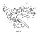
- Figure 1 is a partial front perspective view of a bicycle equipped with a first pair of main bar end electric shifters (brake/shift control devices) mounted to free ends of a bull horn handlebar and a pair of additional attachment bars with a second pair of additional bar end electric shifters (shift control devices) mounted to the free ends of the attachment bars in accordance with a first embodiment;
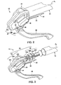
- Figure 2 is an enlarged inside perspective view of the right main bar end electric shifter attached to the right free end of the bull horn handlebar illustrated in Figure 1 ;
- Figure 3 is an inside perspective view of the right main bar end electric shifter prior to attachment to the right free end of the bull horn handlebar illustrated in Figures 1 and 2 ;
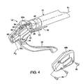
- Figure 4 is an inside perspective view of the right main bar end electric shifter illustrated in Figures 1 to 3 with the inside cover exploded outwardly to reveal the internal shifting components;
- Figure 5 is an inside perspective view of the right main bar end electric shifter illustrated in Figures 1 to 4 with the internal shifting components exploded outwardly from the electrical switch housing portion;
- Figure 6 is an enlarged inside perspective view of the right additional bar end electric shifter attached to the free end of the right additional attachment bar illustrated in Figure 1 ;
- Figure 7 is an inside perspective view of the right additional bar end electric shifter prior to attachment to the free end of the right additional attachment bar illustrated in Figures 1 and 6 ;
- Figure 8 is an inside perspective view of the right additional bar end electric shifter illustrated in Figures 1 , 6 and 7 with the inside cover exploded outwardly to reveal the internal shifting components;
- Figure 9 is an inside perspective view of the right additional bar end electric shifter illustrated in Figures 1 and 6 to 8 with the internal shifting components exploded outwardly from the electrical switch housing portion;
- Figure 10 is an outside perspective view of the right additional bar end electric shifter illustrated in Figures 1 and 6 to 9 with the internal shifting components exploded outwardly from the electrical switch housing portion;
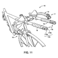
- Figure 11 is a partial front perspective view of the bicycle illustrated in Figure , but with a pair of additional bar end electric shifters (shift control devices) mounted to the free ends of the attachment bars in accordance with a second embodiment;
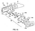
- Figure 12 is an inside perspective view of the right additional bar end electric shifter illustrated in Figure 11 with the internal shifting components exploded outwardly from the electrical switch housing portion;
- Figure 13 is an outside perspective view of the right additional bar end electric shifter illustrated in Figures 11 and 12 with the internal shifting components exploded outwardly from the electrical switch housing portion.
- a bicycle 10 is illustrated with a pair of main bar end electric shifters 11 and 12 coupled to free ends of a bull horn handlebar 13 in accordance with a first embodiment.
- the main bar end electric shifters 11 and 12 constitute brake/shift control devices as discussed below.
- the bull horn handlebar 13 is also equipped with a pair of additional attachment bars 15 and 16 with an additional bar end electric shifter 17 mounted to the free end of the attachment bar 15 having, and an additional bar end electric shifter 18 with mounted to the free end of the attachment bar 16.
- the additional bar end electric shifters 17 and 18 constitute shift control devices as discussed below.
- the main bar end electric shifters 11 and 12 and the additional bar end electric shifters 17 and 18 form parts of a brake and shift control system of the bicycle 10.
- One of the main bar end electric shifters 11 and 12 and one of the additional bar end electric shifters 17 and 18 are operatively coupled to a rear derailleur (not shown), the other ones of the main bar end electric shifters 11 and 12 and the additional bar end electric shifters 17 and 18 are operatively coupled to a front derailleur (not shown).
- deraille and braking devices as well as other conventional bicycle parts of the bicycle 10 are well known in the bicycle art, the derailleurs, the braking devices and the other bicycle parts of the bicycle 10 will not be discussed or illustrated in detail herein, except for the parts relating to the present invention.
- various conventional bicycle parts which are not illustrated and/or discussed in detail herein, can also be used in conjunction with the present invention.
- the main bar end electric shifter 12 mainly includes a base member 24, an electrical shift control switch assembly 26 and a brake lever 28.
- the base member 24 houses electrical shift control switch assembly 26 and pivotally supports the brake lever 28.
- the electrical shift control switch assembly 26 is electrically coupled to an electric derailleur or some other type of gear shifting device by an electrical cord 30.
- the brake lever 28 is connected to one end of a brake cable 32 to mechanically operate a braking device.
- the base member 24 is mounted within the right free end of the handlebar 13 such that the electrical shift control switch assembly 26 is operated on the inwardly facing side of the base member 24, and the brake lever 28 extends downwardly and generally parallel to a main center longitudinal axis A 1 of the handlebar 13.
- the electrical cord 30 and the brake cable 32 extend along outer surfaces of the handlebar 13, and are preferably covered by handlebar tape as seen in Figure 1 .
- the base member 24 includes a handlebar mounting portion 40 and an electrical switch housing portion 42.
- the handlebar mounting portion 40 is configured to be fixedly mounted to a free end of the handlebar 13.
- the electrical switch housing portion 42 extending longitudinally from the handlebar mounting portion 40 and houses the electrical shift control switch assembly 26.
- the handlebar mounting portion 40 and the electrical switch housing portion 42 are primarily formed of a hard rigid plastic material.
- the handlebar mounting portion 40 basically has a stationary projection 40a, a plurality of expansion members 40b coupled together by an elastic ring member 40c and a fixing bolt 40d.
- these parts 40a to 40d of the handlebar mounting portion 40 are configured and arranged to fixedly mount to the base member 24 to the free end of the handlebar 13.
- the handlebar mounting portion 40 is basically an expandable unit that is slidable within the free end of the handlebar 13 when in a first (unexpanded) configuration and non-slidable within the free end of the handlebar 13 when in a second (expanded) configuration.
- the stationary projection 40a is sized to be received inside the free end of the handlebar 13.
- the stationary projection 40a is preferable a tubular with a threaded bore and an outer surface with wedges that partially define a frustoconical shape.
- the expansion members 40b are preferably curved, arc-shaped members that are circumferentially arranged about a longitudinal axis of the fixing bolt 40d to move radially outwardly upon axially moving the fixing bolt 40d (i.e., screwing the fixing bolt 40d into the threaded bore of the stationary projection 40a).
- the expandable unit includes three of the expansion members 40b.
- Each of the expansion members 40b includes a pair of opposed, arc-shaped inclined surfaces, and an outer groove.
- the elastic ring member 40c is preferably a continuous annular O-ring that is constructed of a resilient material such as rubber.
- the elastic ring member 40c extends around the expansion members 40b to retain the expansion members 40b together with the fixing bolt 40d.
- the arc shaped inclined surfaces of the expansion members 40b form a substantially frustoconically shaped wedges.
- the wedges of the stationary projection 40a contact corresponding wedges of the expansion members 40b.
- the electrical switch housing portion 42 is configured to house the electrical shift control switch assembly 26 and pivotally support the brake lever 28.
- the electrical switch housing portion 42 has a body part 42a and a cover part 42b that form a hollow interior for housing the electrical shift control switch assembly 26.
- the bottom of the body part 42a has a pair of brake lever mounting flanges 42c for pivotally supporting the brake lever 28 by a pivot pin 44 between a rest position and a braking position.
- the body part 42a of the electrical switch housing portion 42 and the stationary projection 40a of the handlebar mounting portion 40 are integrally formed together as a one-piece, unitary member.
- the cover part 42b is fastened to the body part 42a by three fasteners 46 such as screws. When the fasteners 46 are unthreaded from holes in the body part 42a and the cover part 42b is detached from the body part 42a, the electrical shift control switch assembly 26 can be removed from the base member 24 without detaching the handlebar mounting portion 40 from the handlebar 13.
- the cover part 42b forms a first lateral side of the electrical switch housing portion 42 that faces towards a vertical center plane of the bicycle 10 when the handlebar mounting portion 40 is mounted to the free end of the handlebar 13.
- the body part 42a forms a second lateral side of the electrical switch housing portion 42 that is opposite to the cover part 42b and faces away from the vertical center plane of the bicycle 10.
- the center axis A 1 of the free end of the handlebar 13 extends longitudinally through the electrical switch housing portion 42 between the first and second lateral sides when the handlebar mounting portion 40 is mounted to the free end of the handlebar 13.
- the electrical shift control switch assembly 26 basically includes an electrical switch 48, a first electrical shift operating member 51 and a second electrical shift operating member 52.
- the electrical switch 48 is fixedly mounted to the body part 42a of the electrical switch housing portion 42 by a pair of screws 54, while the electrical shift operating members 51 and 52 are pivotally mounted to the body part 42a of the electrical switch housing portion 42 by a single pivot pin 56.
- the electrical shift operating members 51 and 52 are located on the lateral side of the electrical switch housing portion 42 that faces towards the vertical center plane of the bicycle 10.
- the electrical shift operating members 51 and 52 protrude outwardly from the cover part 42b of the electrical switch housing portion 42.
- the electrical shift operating member 51 protrudes out from the cover part 42b by a greater amount than the second shift operating member 52.
- the first electrical shift operating member 51 is disposed below the second shift operating member 52.
- the electrical shift operating members 51 and 52 pivot about an operating axis A 2 .
- the electrical shift operating members 51 and 52 are preferably moved relative to the base member 24 between a neutral position and an actuating position. Accordingly, the electrical shift control switch assembly 26 (i.e., electrical shift operating members 51 and 52) can be utilized for both upshifting and downshifting one of the derailleurs.
- the electrical shift operating member 51 is an upshift button that depressed to upshift towards a higher gear
- the electrical shift operating member 52 is a downshift button that depressed to downshift towards a lower gear.
- upshifting and downshifting operations of the electrical shift operating members 51 and 52 could be reversed if needed and/or desired, depending on how the electrical cord 30 is connected.
- the electrical shift control switch assembly 26 is electrically coupled to the electrical cord 30 having one or more electrical conductors.
- the electrical shift operating member 51 is biased outwardly by a pair of springs 58a and 58b, while the electrical shift operating member 52 is biased outwardly by a pair of springs 60a and 60b.
- the spring 58b engages a contact actuating projection 61 to hold the contact actuating projection 61 in a recess on the rear surface of the electrical shift operating member 51.
- the spring 60b engages a contact actuating projection 62 to hold the contact actuating projection 62 in a recess on the rear surface of the electrical shift operating member 52.
- the springs 58a and 58b are compressed and the contact actuating projection 61 depresses a first contact of the electrical switch 48 to send a shift signal.
- the springs 60a and 60b are compressed and the contact actuating projection 62 depresses a second contact of the electrical switch 48 to send a shift signal.
- the contact actuating projections 61 and 61 are the same as those used in the additional bar end electric shifter 18 discussed below.
- the precise structure of the electrical shift control switch assembly 26 is not important to the understanding of the illustrated embodiment and can be construction in a variety of ways to carry out the present invention.
- the additional bar end electric shifters 17 and 18 are essentially identical in construction and operation, except that they are mirror images of each other, only the additional bar end electric shifter 18 will be discussed and illustrated in detail herein. Moreover, the additional bar end electric shifters 17 and 18 are similar in construction and operation to the main bar end electric shifters 11 and 12, discussed above, except that the braking aspect of the main bar end electric shifters 11 and 12 as has been eliminated from the additional bar end electric shifters 17 and 18.
- the additional bar end electric shifter 18 mainly includes a base member 64 and an electrical shift control switch assembly 66.
- the base member 64 houses electrical shift control switch assembly 66.
- the electrical shift control switch assembly 66 is electrically coupled to an electric derailleur or some other type of gear shifting device by an electrical cord 68.
- the base member 64 is mounted within the free end of the additional attachment bar 16 such that the electrical shift control switch assembly 66 is operated on the inwardly facing side of the base member 64.
- the electrical cord 68 extends along outer surfaces of the additional attachment bar 16, and is preferably covered by handlebar tape as seen in Figure 1 .
- the base member 64 includes a handlebar mounting portion 70 and an electrical switch housing portion 72 with an internal switch mounting plate 74.
- the handlebar mounting portion 70 is configured to be fixedly mounted to a free end of the additional attachment bar 16.
- the electrical switch housing portion 72 extending longitudinally from the handlebar mounting portion 70 and houses the electrical shift control switch assembly 66.
- the handlebar mounting portion 70 and the electrical switch housing portion 72 are primarily formed of a hard rigid plastic material.
- the handlebar mounting portion 70 basically has a stationary projection 70a, a plurality of expansion members 70b coupled together by an elastic ring member 70c and a fixing bolt 70d.
- these parts 70a to 70d of the handlebar mounting portion 70 are configured and arranged to fixedly mount to the base member 64 to the free end of the additional attachment bar 16.
- the handlebar mounting portion 70 is basically an expandable unit that is slidable within the free end of the additional attachment bar 16 when in a first (unexpanded) configuration and non-slidable within the free end of the additional attachment bar 16 when in a second (expanded) configuration.
- the stationary projection 70a is sized to be received inside the free end of the additional attachment bar 16.
- the stationary projection 70a is preferable a tubular with a threaded bore and an outer surface with wedges that partially define a frustoconical shape.
- the expansion members 70b are preferably curved, arc-shaped members that are circumferentially arranged about a longitudinal axis of the fixing bolt 70d to move radially outwardly upon axially moving the fixing bolt 70d (i.e., screwing the fixing bolt 70d into the threaded bore of the stationary projection 70a).
- the expandable unit includes three of the expansion members 70b.
- Each of the expansion members 70b includes a pair of opposed, arc-shaped inclined surfaces, and an outer groove.
- the elastic ring member 70c is preferably a continuous annular O-ring that is constructed of a resilient material such as rubber.
- the elastic ring member 70c extends around the expansion members 70b to retain the expansion members 70b together with the fixing bolt 70d.
- the arc shaped inclined surfaces of the expansion members 70b form a substantially frustoconically shaped wedges.
- the wedges of the stationary projection 70a contact corresponding wedges of the expansion members 70b.
- the electrical switch housing portion 72 is configured to house the electrical shift control switch assembly 66 on the internal switch mounting plate 74.
- the electrical switch housing portion 72 has a body part 72a and a cover part 72b that form a hollow interior for housing the electrical shift control switch assembly 66 on the internal switch mounting plate 74.
- the electrical switch housing portion 72 extends longitudinally from the handlebar mounting portion 70 such that a main center longitudinal axis A 3 of the free end of the additional attachment bar 16 extends longitudinally through the electrical switch housing portion 72.
- the body part 72a of the electrical switch housing portion 72 and the stationary projection 70a of the handlebar mounting portion 70 are integrally formed together as a one-piece, unitary member.
- the internal switch mounting plate 74 is fastened to the body part 72a by a fastener 76 such as a screw.
- the internal switch mounting plate 74 is fastened to the cover part 72b by two fasteners 77 such as screws.
- the cover part 72b forms a first lateral side of the electrical switch housing portion 72 that faces towards a vertical center plane of the bicycle 10 when the handlebar mounting portion 70 is mounted to the free end of the additional attachment bar 16.
- the body part 72a forms a second lateral side of the electrical switch housing portion 72 that is opposite to the cover part 72b and faces away from the vertical center plane of the bicycle 10.
- the center axis A 3 of the free end of the additional attachment bar 16 extends longitudinally through the electrical switch housing portion 72 between the first and second lateral sides when the handlebar mounting portion 70 is mounted to the free end of the additional attachment bar 16.
- the electrical shift control switch assembly 66 basically includes an electrical switch 78, a first electrical shift operating member 81 and a second electrical shift operating member 82.
- the electrical switch 78 is fixedly mounted to the internal switch mounting plate 74 of the electrical switch housing portion 72 by a pair of screws 84, while the electrical shift operating members 81 and 82 are pivotally mounted to the internal switch mounting plate 74 by a single pivot pin 86.
- the electrical shift operating members 81 and 82 are located on the lateral side of the electrical switch housing portion 72 that faces towards the vertical center plane of the bicycle 10.
- the electrical shift operating members 81 and 82 protrude outwardly from the cover part 72b of the electrical switch housing portion 72.
- the electrical shift operating member 81 protrudes out from the cover part 72b by a greater amount than the second shift operating member 82.
- the first electrical shift operating member 81 is disposed below the second shift operating member 82.
- the electrical shift operating members 81 and 82 pivot about an operating axis A 4 .
- the electrical shift operating members 81 and 82 are preferably moved relative to the base member 64 between a neutral position and an actuating position.
- the electrical shift control switch assembly 66 (i.e., electrical shift operating members 81 and 82) can be utilized for both upshifting and downshifting one of the derailleurs.
- the electrical shift operating member 81 is an upshift button that depressed to upshift towards a higher gear
- the electrical shift operating member 82 is a downshift button that depressed to downshift towards a lower gear.
- the upshifting and downshifting operations of the electrical shift operating members 81 and 82 could be reversed if needed and/or desired, depending on how the electrical cord 68 is connected.
- the electrical shift control switch assembly 66 is electrically coupled to the electrical cord 68 which has one or more electrical conductors.
- the electrical shift operating member 81 is biased outwardly by a pair of springs 88a and 88b, while the electrical shift operating member 82 is biased outwardly by a pair of springs 90a and 90b.
- the spring 88b engages a contact actuating projection 92 to hold the contact actuating projection 92 in a recess on the rear surface of the electrical shift operating member 81.
- the spring 90b engages a contact actuating projection 94 to hold the contact actuating projection 94 in a recess on the rear surface of the electrical shift operating member 82.
- the springs 88a and 88b are compressed and the contact actuating projection 92 depresses a first contact of the electrical switch 78 to send a shift signal.
- the springs 90a and 90b are compressed and the contact actuating projection 92 depresses a second contact of the electrical switch 78 to send a shift signal.
- the precise structure of the electrical shift control switch assembly 66 is not important to the understanding of the illustrated embodiment and can be construction in a variety of ways to carry out the present invention.
- the bicycle 10 has been equipped with a pair of additional bar end electric shifters 118 in accordance with another embodiment.
- the additional bar end electric shifter 118 is similar to the additional bar end electric shifter 18, except as explained below.
- the additional bar end electric shifter 118 mainly includes a base member 164 and an electrical shift control switch assembly 166.
- the base member 164 houses electrical shift control switch assembly 166.
- the electrical shift control switch assembly 166 is electrically coupled to an electric derailleur or some other type of gear shifting device by the electrical cord 68.
- the base member 164 includes a handlebar mounting portion 170 and an electrical switch housing portion 172 with an internal switch mounting plate 174.
- the handlebar mounting portion 170 is configured to be fixedly mounted to a free end of the additional attachment bar 16.
- the electrical switch housing portion 172 extending longitudinally from the handlebar mounting portion 170 and houses the electrical shift control switch assembly 166.
- the handlebar mounting portion 170 and the electrical switch housing portion 172 are primarily formed of a hard rigid plastic material.
- the handlebar mounting portion 170 is identical to the handlebar mounting portion 70, as discussed above, and thus, the handlebar mounting portion 170 will not be discussed or illustrated for the sake of brevity.
- the electrical switch housing portion 172 is configured to house the electrical shift control switch assembly 166 on the internal switch mounting plate 174. As seen in Figure 11 , the electrical switch housing portion 172 has a body part 172a and a cover part 172b that form a hollow interior for housing the electrical shift control switch assembly 166 on the internal switch mounting plate 174.
- the internal switch mounting plate 174 is fastened to the body part 172a by a fastener 176 such as a screw. Also the internal switch mounting plate 174 is fastened to the cover part 172b by two fasteners 177 such as screws. When the fasteners 176 are unthreaded from holes in the body part 172a and the cover part 172b is detached from the body part 172a, the electrical shift control switch assembly 166 can be removed from the base member 164 without detaching the handlebar mounting portion 170 from the additional attachment bar 16.
- the electrical shift control switch assembly 166 basically includes an electrical switch 178, a first electrical shift operating member 181 and a second electrical shift operating member 182.
- the electrical switch 178 is fixedly mounted to the internal switch mounting plate 174 of the electrical switch housing portion 172 by a pair of screws 184, while the electrical shift operating members 181 and 182 are pivotally mounted to opposite sides of the internal switch mounting plate 174 by a pair of pivot pins 186a and 186b.
- the electrical shift operating members 181 and 182 face in opposite lateral directions of the electrical switch housing portion 172.
- the electrical shift operating member 181 protrudes outwardly from the cover part 172b of the electrical switch housing portion 172, while the electrical shift operating member 182 protrudes outwardly from the body part 172a of the electrical switch housing portion 172.
- the electrical shift operating members 181 and 182 are moved relative to the base member 164 between a neutral position and an actuating position by depressing the electrical shift operating members 181 and 182 inwardly of the electrical switch housing portion 172.
- the electrical shift control switch assembly 166 i.e., electrical shift operating members 181 and 182 can be utilized for both upshifting and downshifting one of the derailleurs.
- the additional bar end electric shifter 118 is mounted so that inwardly facing one of the electrical shift operating members 181 and 182 is an upshift button for shifting towards a higher gear, while the outwardly facing one of the electrical shift operating members 181 and 182 is a downshift button for shifting towards a lower gear.
- the upshifting and downshifting operations of the electrical shift operating members 181 and 182 could be reversed if needed and/or desired, depending on how the electrical cord 68 is connected.
- the electrical shift operating member 181 is biased outwardly by a pair of springs 188a and 188b, while the electrical shift operating member 182 is biased outwardly by a pair of springs 190a and 190b.
- the spring 188b engages a contact actuating projection 192 to hold the contact actuating projection 192 in a recess on the rear surface of the electrical shift operating member 181.
- the spring 190b engages a contact actuating projection 194 to hold the contact actuating projection 194 in a recess on the rear surface of the electrical shift operating member 182.
- the springs 188a and 188b are compressed and the contact actuating projection 192 depresses a first contact of the electrical switch 178 to send a shift signal.
- the springs 190a and 190b are compressed and the contact actuating projection 192 depresses a second contact of the electrical switch 178 to send a shift signal.
- the precise structure of the electrical shift control switch assembly 166 is not important to the understanding of the illustrated embodiment and can be construction in a variety of ways to carry out the present invention.
- the following directional terms "forward, rearward, above, downward, vertical, horizontal, below and transverse” as well as any other similar directional terms refer to those directions of a bicycle equipped with the present invention. Accordingly, these terms, as utilized to describe the present invention should be interpreted relative to a bicycle equipped with the present invention. Also in understanding the scope of the present invention, the term “comprising” and its derivatives, as used herein, are intended to be open ended terms that specify the presence of the stated features, elements, components, groups, integers, and/or steps, but do not exclude the presence of other unstated features, elements, components, groups, integers and/or steps.
Landscapes
- Engineering & Computer Science (AREA)
- Mechanical Engineering (AREA)
- Chemical & Material Sciences (AREA)
- Combustion & Propulsion (AREA)
- Transportation (AREA)
- Steering Devices For Bicycles And Motorcycles (AREA)
- Arrangement Or Mounting Of Control Devices For Change-Speed Gearing (AREA)
- Automatic Cycles, And Cycles In General (AREA)
Description
- This invention generally relates to a bicycle control device for performing a shifting operation. More specifically, the present invention relates to a bar end electric shifter which is configured to be mounted to the free end of a bicycle handlebar in an integrated manner. Background Information
- Bicycling is becoming an increasingly more popular form of recreation as well as a means of transportation. Moreover, bicycling has become a very popular competitive sport for both amateurs and professionals. Whether the bicycle is used for recreation, transportation or competition, the bicycle industry is constantly improving the various components of the bicycle, especially the bicycle control devices for shifting and braking.
- In the past, bicycle shifters were mechanically operated devices that were sometimes located near the brake levers of the bicycle. Thus, an operating force was typically applied by one of the rider's fingers to operate a shift control lever, which in turn transmitted the operating force to the drive component of a bicycle shifting mechanism by a cable that was fixed at one end to the control lever. More recently, electric switches have been used instead of mechanical control levers in order to operate the bicycle shifting mechanism. One example of an electrical shift control device is disclosed in
U.S. Patent No. 5,358,451 . This patent discloses a plurality of electric switches may be provided at a plurality of handlebar locations in order to allow for quicker shifts and to enhance responsiveness. Another example of an electrical shift control device is disclosed inU.S. Patent Application Publication No. 20005/0211014 EP 1 808 367 discloses a bar end electric shifter according to the preamble of claim 1. - In view of the above, it will be apparent to those skilled in the art from this disclosure that there exists a need for an improved bicycle control device. This invention addresses this need in the art as well as other needs, which will become apparent to those skilled in the art from this disclosure.
- One object of the present invention is to provide a bar end electric shifter having two electrical shift switches that can be easily operated.
- The foregoing objects can basically be attained by providing a bar end electric shifter that basically comprises a handlebar mounting portion, an electrical switch housing portion, a first electrical shift operating member and a second electrical shift operating member. The handlebar mounting portion is configured to be fixedly mounted to a free end of a bicycle handlebar. The electrical switch housing portion extends longitudinally from the handlebar mounting portion. The electrical switch housing portion has first and second lateral sides with a center axis of the free end of the handlebar extends longitudinally through the electrical switch housing portion when the handlebar mounting portion is mounted to the free end of the bicycle handlebar. The first electrical shift operating member is located on one of the lateral sides of the electrical switch housing portion. The second electrical shift operating member is located on one of the lateral sides of the electrical switch housing portion. The first and second electrical shift operating members both disposed on the first lateral side the electrical switch housing portion. The first and second electrical shift operating members protrude outwardly from the electrical switch housing portion with the first electrical shift operating member protruding a greater amount than the second shift operating member.
- These and other objects, features, aspects and advantages of the present invention will become apparent to those skilled in the art from the following detailed description, which, taken in conjunction with the annexed drawings, discloses preferred embodiments of the present invention.
- Referring now to the attached drawings which form a part of this original disclosure:
-
Figure 1 is a partial front perspective view of a bicycle equipped with a first pair of main bar end electric shifters (brake/shift control devices) mounted to free ends of a bull horn handlebar and a pair of additional attachment bars with a second pair of additional bar end electric shifters (shift control devices) mounted to the free ends of the attachment bars in accordance with a first embodiment; -
Figure 2 is an enlarged inside perspective view of the right main bar end electric shifter attached to the right free end of the bull horn handlebar illustrated inFigure 1 ; -
Figure 3 is an inside perspective view of the right main bar end electric shifter prior to attachment to the right free end of the bull horn handlebar illustrated inFigures 1 and2 ; -
Figure 4 is an inside perspective view of the right main bar end electric shifter illustrated inFigures 1 to 3 with the inside cover exploded outwardly to reveal the internal shifting components; -
Figure 5 is an inside perspective view of the right main bar end electric shifter illustrated inFigures 1 to 4 with the internal shifting components exploded outwardly from the electrical switch housing portion; -
Figure 6 is an enlarged inside perspective view of the right additional bar end electric shifter attached to the free end of the right additional attachment bar illustrated inFigure 1 ; -
Figure 7 is an inside perspective view of the right additional bar end electric shifter prior to attachment to the free end of the right additional attachment bar illustrated inFigures 1 and6 ; -
Figure 8 is an inside perspective view of the right additional bar end electric shifter illustrated inFigures 1 ,6 and 7 with the inside cover exploded outwardly to reveal the internal shifting components; -
Figure 9 is an inside perspective view of the right additional bar end electric shifter illustrated inFigures 1 and6 to 8 with the internal shifting components exploded outwardly from the electrical switch housing portion; -
Figure 10 is an outside perspective view of the right additional bar end electric shifter illustrated inFigures 1 and6 to 9 with the internal shifting components exploded outwardly from the electrical switch housing portion; -
Figure 11 is a partial front perspective view of the bicycle illustrated in Figure , but with a pair of additional bar end electric shifters (shift control devices) mounted to the free ends of the attachment bars in accordance with a second embodiment; -
Figure 12 is an inside perspective view of the right additional bar end electric shifter illustrated inFigure 11 with the internal shifting components exploded outwardly from the electrical switch housing portion; and -
Figure 13 is an outside perspective view of the right additional bar end electric shifter illustrated inFigures 11 and12 with the internal shifting components exploded outwardly from the electrical switch housing portion. - Selected embodiments of the present invention will now be explained with reference to the drawings. It will be apparent to those skilled in the art from this disclosure that the following descriptions of the embodiments of the present invention are provided for illustration only and not for the purpose of limiting the invention as defined by the appended claims and their equivalents.
- Referring initially to
Figure 1 , abicycle 10 is illustrated with a pair of main bar endelectric shifters bull horn handlebar 13 in accordance with a first embodiment. The main bar endelectric shifters bull horn handlebar 13 is also equipped with a pair ofadditional attachment bars electric shifter 17 mounted to the free end of theattachment bar 15 having, and an additional bar endelectric shifter 18 with mounted to the free end of theattachment bar 16. The additional bar endelectric shifters electric shifters electric shifters bicycle 10. - One of the main bar end
electric shifters electric shifters electric shifters electric shifters bicycle 10 are well known in the bicycle art, the derailleurs, the braking devices and the other bicycle parts of thebicycle 10 will not be discussed or illustrated in detail herein, except for the parts relating to the present invention. Moreover, various conventional bicycle parts, which are not illustrated and/or discussed in detail herein, can also be used in conjunction with the present invention. - Referring now to
Figures 2 to 5 , since the main bar endelectric shifters electric shifter 12 will be discussed and illustrated in detail herein. The main bar endelectric shifter 12 mainly includes abase member 24, an electrical shiftcontrol switch assembly 26 and abrake lever 28. Basically, thebase member 24 houses electrical shiftcontrol switch assembly 26 and pivotally supports thebrake lever 28. The electrical shiftcontrol switch assembly 26 is electrically coupled to an electric derailleur or some other type of gear shifting device by anelectrical cord 30. Thebrake lever 28 is connected to one end of abrake cable 32 to mechanically operate a braking device. - Preferably, the
base member 24 is mounted within the right free end of thehandlebar 13 such that the electrical shiftcontrol switch assembly 26 is operated on the inwardly facing side of thebase member 24, and thebrake lever 28 extends downwardly and generally parallel to a main center longitudinal axis A1 of thehandlebar 13. Theelectrical cord 30 and thebrake cable 32 extend along outer surfaces of thehandlebar 13, and are preferably covered by handlebar tape as seen inFigure 1 . Thebase member 24 includes ahandlebar mounting portion 40 and an electricalswitch housing portion 42. Thehandlebar mounting portion 40 is configured to be fixedly mounted to a free end of thehandlebar 13. The electricalswitch housing portion 42 extending longitudinally from thehandlebar mounting portion 40 and houses the electrical shiftcontrol switch assembly 26. In the illustrated embodiment, thehandlebar mounting portion 40 and the electricalswitch housing portion 42 are primarily formed of a hard rigid plastic material. - As seen in
Figure 3 , thehandlebar mounting portion 40 basically has astationary projection 40a, a plurality ofexpansion members 40b coupled together by anelastic ring member 40c and a fixingbolt 40d. Thus, theseparts 40a to 40d of thehandlebar mounting portion 40 are configured and arranged to fixedly mount to thebase member 24 to the free end of thehandlebar 13. Basically, thehandlebar mounting portion 40 is basically an expandable unit that is slidable within the free end of thehandlebar 13 when in a first (unexpanded) configuration and non-slidable within the free end of thehandlebar 13 when in a second (expanded) configuration. - The
stationary projection 40a is sized to be received inside the free end of thehandlebar 13. Specifically, thestationary projection 40a is preferable a tubular with a threaded bore and an outer surface with wedges that partially define a frustoconical shape. Theexpansion members 40b are preferably curved, arc-shaped members that are circumferentially arranged about a longitudinal axis of the fixingbolt 40d to move radially outwardly upon axially moving the fixingbolt 40d (i.e., screwing the fixingbolt 40d into the threaded bore of thestationary projection 40a). Preferably, the expandable unit includes three of theexpansion members 40b. Each of theexpansion members 40b includes a pair of opposed, arc-shaped inclined surfaces, and an outer groove. Theelastic ring member 40c is preferably a continuous annular O-ring that is constructed of a resilient material such as rubber. Theelastic ring member 40c extends around theexpansion members 40b to retain theexpansion members 40b together with the fixingbolt 40d. The arc shaped inclined surfaces of theexpansion members 40b form a substantially frustoconically shaped wedges. The wedges of thestationary projection 40a contact corresponding wedges of theexpansion members 40b. Thus, when the fixingbolt 40d is rotated to move towards thestationary projection 40a, the wedges cooperate with each other, respectively, to move theexpansion members 40b andelastic ring member 40c (i.e., the expansion structure) radially outwardly. - The electrical
switch housing portion 42 is configured to house the electrical shiftcontrol switch assembly 26 and pivotally support thebrake lever 28. The electricalswitch housing portion 42 has abody part 42a and acover part 42b that form a hollow interior for housing the electrical shiftcontrol switch assembly 26. The bottom of thebody part 42a has a pair of brakelever mounting flanges 42c for pivotally supporting thebrake lever 28 by apivot pin 44 between a rest position and a braking position. When thebase member 24 is mounted to the free end of thehandlebar 13, the electricalswitch housing portion 42 extends longitudinally from thehandlebar mounting portion 40 such that the main center longitudinal axis A1 of the free end of thehandlebar 13 extends longitudinally through the electricalswitch housing portion 42. - In the illustrated embodiment, the
body part 42a of the electricalswitch housing portion 42 and thestationary projection 40a of thehandlebar mounting portion 40 are integrally formed together as a one-piece, unitary member. Thecover part 42b is fastened to thebody part 42a by threefasteners 46 such as screws. When thefasteners 46 are unthreaded from holes in thebody part 42a and thecover part 42b is detached from thebody part 42a, the electrical shiftcontrol switch assembly 26 can be removed from thebase member 24 without detaching thehandlebar mounting portion 40 from thehandlebar 13. - The
cover part 42b forms a first lateral side of the electricalswitch housing portion 42 that faces towards a vertical center plane of thebicycle 10 when thehandlebar mounting portion 40 is mounted to the free end of thehandlebar 13. Thebody part 42a forms a second lateral side of the electricalswitch housing portion 42 that is opposite to thecover part 42b and faces away from the vertical center plane of thebicycle 10. In the illustrated embodiment, the center axis A1 of the free end of thehandlebar 13 extends longitudinally through the electricalswitch housing portion 42 between the first and second lateral sides when thehandlebar mounting portion 40 is mounted to the free end of thehandlebar 13. - As seen in
Figures 4 and5 , the electrical shiftcontrol switch assembly 26 basically includes anelectrical switch 48, a first electricalshift operating member 51 and a second electricalshift operating member 52. Theelectrical switch 48 is fixedly mounted to thebody part 42a of the electricalswitch housing portion 42 by a pair ofscrews 54, while the electricalshift operating members body part 42a of the electricalswitch housing portion 42 by asingle pivot pin 56. Thus, in this embodiment, the electricalshift operating members switch housing portion 42 that faces towards the vertical center plane of thebicycle 10. - The electrical
shift operating members cover part 42b of the electricalswitch housing portion 42. In this embodiment, the electricalshift operating member 51 protrudes out from thecover part 42b by a greater amount than the secondshift operating member 52. Also in this embodiment, the first electricalshift operating member 51 is disposed below the secondshift operating member 52. Preferably, the electricalshift operating members shift operating members base member 24 between a neutral position and an actuating position. Accordingly, the electrical shift control switch assembly 26 (i.e., electricalshift operating members 51 and 52) can be utilized for both upshifting and downshifting one of the derailleurs. The electricalshift operating member 51 is an upshift button that depressed to upshift towards a higher gear, while the electricalshift operating member 52 is a downshift button that depressed to downshift towards a lower gear. Of course, it will be apparent to those skilled in the art from this disclosure that the upshifting and downshifting operations of the electricalshift operating members electrical cord 30 is connected. - As seen in
Figure 5 , the electrical shiftcontrol switch assembly 26 is electrically coupled to theelectrical cord 30 having one or more electrical conductors. In the electrical shiftcontrol switch assembly 26 of the illustrated embodiment, the electricalshift operating member 51 is biased outwardly by a pair ofsprings shift operating member 52 is biased outwardly by a pair ofsprings spring 58b engages acontact actuating projection 61 to hold thecontact actuating projection 61 in a recess on the rear surface of the electricalshift operating member 51. Similarly, thespring 60b engages acontact actuating projection 62 to hold thecontact actuating projection 62 in a recess on the rear surface of the electricalshift operating member 52. When the electricalshift operating member 51 is depressed, thesprings contact actuating projection 61 depresses a first contact of theelectrical switch 48 to send a shift signal. When the electricalshift operating member 52 is depressed, thesprings contact actuating projection 62 depresses a second contact of theelectrical switch 48 to send a shift signal. Thecontact actuating projections electric shifter 18 discussed below. The precise structure of the electrical shiftcontrol switch assembly 26 is not important to the understanding of the illustrated embodiment and can be construction in a variety of ways to carry out the present invention. - Referring to
Figures 6 to 10 , since the additional bar endelectric shifters electric shifter 18 will be discussed and illustrated in detail herein. Moreover, the additional bar endelectric shifters electric shifters electric shifters electric shifters - The additional bar end
electric shifter 18 mainly includes abase member 64 and an electrical shiftcontrol switch assembly 66. Basically, thebase member 64 houses electrical shiftcontrol switch assembly 66. The electrical shiftcontrol switch assembly 66 is electrically coupled to an electric derailleur or some other type of gear shifting device by anelectrical cord 68. - Preferably, the
base member 64 is mounted within the free end of theadditional attachment bar 16 such that the electrical shiftcontrol switch assembly 66 is operated on the inwardly facing side of thebase member 64. Theelectrical cord 68 extends along outer surfaces of theadditional attachment bar 16, and is preferably covered by handlebar tape as seen inFigure 1 . Thebase member 64 includes ahandlebar mounting portion 70 and an electricalswitch housing portion 72 with an internalswitch mounting plate 74. Thehandlebar mounting portion 70 is configured to be fixedly mounted to a free end of theadditional attachment bar 16. The electricalswitch housing portion 72 extending longitudinally from thehandlebar mounting portion 70 and houses the electrical shiftcontrol switch assembly 66. In the illustrated embodiment, thehandlebar mounting portion 70 and the electricalswitch housing portion 72 are primarily formed of a hard rigid plastic material. - As seen in
Figure 7 , thehandlebar mounting portion 70 basically has astationary projection 70a, a plurality ofexpansion members 70b coupled together by anelastic ring member 70c and a fixingbolt 70d. Thus, theseparts 70a to 70d of thehandlebar mounting portion 70 are configured and arranged to fixedly mount to thebase member 64 to the free end of theadditional attachment bar 16. Basically, thehandlebar mounting portion 70 is basically an expandable unit that is slidable within the free end of theadditional attachment bar 16 when in a first (unexpanded) configuration and non-slidable within the free end of theadditional attachment bar 16 when in a second (expanded) configuration. - The
stationary projection 70a is sized to be received inside the free end of theadditional attachment bar 16. Specifically, thestationary projection 70a is preferable a tubular with a threaded bore and an outer surface with wedges that partially define a frustoconical shape. Theexpansion members 70b are preferably curved, arc-shaped members that are circumferentially arranged about a longitudinal axis of the fixingbolt 70d to move radially outwardly upon axially moving the fixingbolt 70d (i.e., screwing the fixingbolt 70d into the threaded bore of thestationary projection 70a). Preferably, the expandable unit includes three of theexpansion members 70b. Each of theexpansion members 70b includes a pair of opposed, arc-shaped inclined surfaces, and an outer groove. Theelastic ring member 70c is preferably a continuous annular O-ring that is constructed of a resilient material such as rubber. Theelastic ring member 70c extends around theexpansion members 70b to retain theexpansion members 70b together with the fixingbolt 70d. The arc shaped inclined surfaces of theexpansion members 70b form a substantially frustoconically shaped wedges. The wedges of thestationary projection 70a contact corresponding wedges of theexpansion members 70b. Thus, when the fixingbolt 70d is rotated to move towards thestationary projection 70a, the wedges cooperate with each other, respectively, to move theexpansion members 70b andelastic ring member 70c (i.e., the expansion structure) radially outwardly. - The electrical
switch housing portion 72 is configured to house the electrical shiftcontrol switch assembly 66 on the internalswitch mounting plate 74. The electricalswitch housing portion 72 has abody part 72a and acover part 72b that form a hollow interior for housing the electrical shiftcontrol switch assembly 66 on the internalswitch mounting plate 74. When thebase member 64 is mounted to the free end of theadditional attachment bar 16, the electricalswitch housing portion 72 extends longitudinally from thehandlebar mounting portion 70 such that a main center longitudinal axis A3 of the free end of theadditional attachment bar 16 extends longitudinally through the electricalswitch housing portion 72. - In the illustrated embodiment, the
body part 72a of the electricalswitch housing portion 72 and thestationary projection 70a of thehandlebar mounting portion 70 are integrally formed together as a one-piece, unitary member. The internalswitch mounting plate 74 is fastened to thebody part 72a by afastener 76 such as a screw. Also the internalswitch mounting plate 74 is fastened to thecover part 72b by twofasteners 77 such as screws. When thefasteners 76 are unthreaded from holes in thebody part 72a and thecover part 72b is detached from thebody part 72a, the electrical shiftcontrol switch assembly 66 can be removed from thebase member 64 without detaching thehandlebar mounting portion 70 from theadditional attachment bar 16. - The
cover part 72b forms a first lateral side of the electricalswitch housing portion 72 that faces towards a vertical center plane of thebicycle 10 when thehandlebar mounting portion 70 is mounted to the free end of theadditional attachment bar 16. Thebody part 72a forms a second lateral side of the electricalswitch housing portion 72 that is opposite to thecover part 72b and faces away from the vertical center plane of thebicycle 10. In the illustrated embodiment, the center axis A3 of the free end of theadditional attachment bar 16 extends longitudinally through the electricalswitch housing portion 72 between the first and second lateral sides when thehandlebar mounting portion 70 is mounted to the free end of theadditional attachment bar 16. - As seen in
Figures 9 and10 , the electrical shiftcontrol switch assembly 66 basically includes anelectrical switch 78, a first electricalshift operating member 81 and a second electricalshift operating member 82. Theelectrical switch 78 is fixedly mounted to the internalswitch mounting plate 74 of the electricalswitch housing portion 72 by a pair ofscrews 84, while the electricalshift operating members switch mounting plate 74 by asingle pivot pin 86. Thus, in this embodiment, the electricalshift operating members switch housing portion 72 that faces towards the vertical center plane of thebicycle 10. - The electrical
shift operating members cover part 72b of the electricalswitch housing portion 72. In this embodiment, the electricalshift operating member 81 protrudes out from thecover part 72b by a greater amount than the secondshift operating member 82. Also in this embodiment, the first electricalshift operating member 81 is disposed below the secondshift operating member 82. Preferably, the electricalshift operating members shift operating members base member 64 between a neutral position and an actuating position. Accordingly, the electrical shift control switch assembly 66 (i.e., electricalshift operating members 81 and 82) can be utilized for both upshifting and downshifting one of the derailleurs. The electricalshift operating member 81 is an upshift button that depressed to upshift towards a higher gear, while the electricalshift operating member 82 is a downshift button that depressed to downshift towards a lower gear. Of course, it will be apparent to those skilled in the art from this disclosure that the upshifting and downshifting operations of the electricalshift operating members electrical cord 68 is connected. - As seen in
Figure 9 , the electrical shiftcontrol switch assembly 66 is electrically coupled to theelectrical cord 68 which has one or more electrical conductors. In the electrical shiftcontrol switch assembly 66 of this illustrated embodiment, the electricalshift operating member 81 is biased outwardly by a pair ofsprings shift operating member 82 is biased outwardly by a pair ofsprings spring 88b engages acontact actuating projection 92 to hold thecontact actuating projection 92 in a recess on the rear surface of the electricalshift operating member 81. Similarly, thespring 90b engages acontact actuating projection 94 to hold thecontact actuating projection 94 in a recess on the rear surface of the electricalshift operating member 82. When the electricalshift operating member 81 is depressed, thesprings contact actuating projection 92 depresses a first contact of theelectrical switch 78 to send a shift signal. When the electricalshift operating member 82 is depressed, thesprings contact actuating projection 92 depresses a second contact of theelectrical switch 78 to send a shift signal. The precise structure of the electrical shiftcontrol switch assembly 66 is not important to the understanding of the illustrated embodiment and can be construction in a variety of ways to carry out the present invention. - Referring to
Figures 11 to 13 , thebicycle 10 has been equipped with a pair of additional bar endelectric shifters 118 in accordance with another embodiment. The additional bar endelectric shifter 118 is similar to the additional bar endelectric shifter 18, except as explained below. - The additional bar end
electric shifter 118 mainly includes abase member 164 and an electrical shiftcontrol switch assembly 166. Basically, thebase member 164 houses electrical shiftcontrol switch assembly 166. The electrical shiftcontrol switch assembly 166 is electrically coupled to an electric derailleur or some other type of gear shifting device by theelectrical cord 68. - Preferably, the
base member 164 includes ahandlebar mounting portion 170 and an electricalswitch housing portion 172 with an internalswitch mounting plate 174. Thehandlebar mounting portion 170 is configured to be fixedly mounted to a free end of theadditional attachment bar 16. The electricalswitch housing portion 172 extending longitudinally from thehandlebar mounting portion 170 and houses the electrical shiftcontrol switch assembly 166. In the illustrated embodiment, thehandlebar mounting portion 170 and the electricalswitch housing portion 172 are primarily formed of a hard rigid plastic material. Thehandlebar mounting portion 170 is identical to thehandlebar mounting portion 70, as discussed above, and thus, thehandlebar mounting portion 170 will not be discussed or illustrated for the sake of brevity. - The electrical
switch housing portion 172 is configured to house the electrical shiftcontrol switch assembly 166 on the internalswitch mounting plate 174. As seen inFigure 11 , the electricalswitch housing portion 172 has abody part 172a and acover part 172b that form a hollow interior for housing the electrical shiftcontrol switch assembly 166 on the internalswitch mounting plate 174. - In the illustrated embodiment, the internal
switch mounting plate 174 is fastened to thebody part 172a by afastener 176 such as a screw. Also the internalswitch mounting plate 174 is fastened to thecover part 172b by twofasteners 177 such as screws. When thefasteners 176 are unthreaded from holes in thebody part 172a and thecover part 172b is detached from thebody part 172a, the electrical shiftcontrol switch assembly 166 can be removed from thebase member 164 without detaching thehandlebar mounting portion 170 from theadditional attachment bar 16. - As seen in
Figures 12 and13 , the electrical shiftcontrol switch assembly 166 basically includes anelectrical switch 178, a first electricalshift operating member 181 and a second electricalshift operating member 182. Theelectrical switch 178 is fixedly mounted to the internalswitch mounting plate 174 of the electricalswitch housing portion 172 by a pair ofscrews 184, while the electricalshift operating members switch mounting plate 174 by a pair ofpivot pins shift operating members switch housing portion 172. - The electrical
shift operating member 181 protrudes outwardly from thecover part 172b of the electricalswitch housing portion 172, while the electricalshift operating member 182 protrudes outwardly from thebody part 172a of the electricalswitch housing portion 172. Preferably, the electricalshift operating members base member 164 between a neutral position and an actuating position by depressing the electricalshift operating members switch housing portion 172. Accordingly, the electrical shift control switch assembly 166 (i.e., electricalshift operating members 181 and 182) can be utilized for both upshifting and downshifting one of the derailleurs. Preferably, the additional bar endelectric shifter 118 is mounted so that inwardly facing one of the electricalshift operating members shift operating members shift operating members electrical cord 68 is connected. - In the electrical shift
control switch assembly 166 of this illustrated embodiment, the electricalshift operating member 181 is biased outwardly by a pair ofsprings shift operating member 182 is biased outwardly by a pair ofsprings spring 188b engages acontact actuating projection 192 to hold thecontact actuating projection 192 in a recess on the rear surface of the electricalshift operating member 181. Similarly, thespring 190b engages acontact actuating projection 194 to hold thecontact actuating projection 194 in a recess on the rear surface of the electricalshift operating member 182. When the electricalshift operating member 181 is depressed, thesprings contact actuating projection 192 depresses a first contact of theelectrical switch 178 to send a shift signal. When the electricalshift operating member 182 is depressed, thesprings contact actuating projection 192 depresses a second contact of theelectrical switch 178 to send a shift signal. The precise structure of the electrical shiftcontrol switch assembly 166 is not important to the understanding of the illustrated embodiment and can be construction in a variety of ways to carry out the present invention. - As used herein to describe the present invention, the following directional terms "forward, rearward, above, downward, vertical, horizontal, below and transverse" as well as any other similar directional terms refer to those directions of a bicycle equipped with the present invention. Accordingly, these terms, as utilized to describe the present invention should be interpreted relative to a bicycle equipped with the present invention. Also in understanding the scope of the present invention, the term "comprising" and its derivatives, as used herein, are intended to be open ended terms that specify the presence of the stated features, elements, components, groups, integers, and/or steps, but do not exclude the presence of other unstated features, elements, components, groups, integers and/or steps. The foregoing also applies to words having similar meanings such as the terms, "including", "having" and their derivatives. Also, the terms "member" or "element" when used in the singular can have the dual meaning of a single part or a plurality of parts. Finally, terms of degree such as "substantially", "about" and "approximately" as used herein mean a reasonable amount of deviation of the modified term such that the end result is not significantly changed.
- While only selected embodiments have been chosen to illustrate the present invention, it will be apparent to those skilled in the art from this disclosure that various changes and modifications can be made herein without departing from the scope of the invention as defined in the appended claims. For example, the size, shape, location or orientation of the various components can be changed as needed and/or desired. Components that are shown directly connected or contacting each other can have intermediate structures disposed between them. The functions of one element can be performed by two, and vice versa. The structures and functions of one embodiment can be adopted in another embodiment. It is not necessary for all advantages to be present in a particular embodiment at the same time. Thus, the foregoing descriptions of the embodiments according to the present invention are provided for illustration only, and not for the purpose of limiting the invention as defined by the appended claims and their equivalents.
Claims (7)
- A bar end electric shifter (11) comprising:a handlebar mounting portion (40)configured to be fixedly mounted to a free end of a bicycle handlebar;an electrical switch housing portion (42) extending longitudinally from the handlebar mounting portion (40), the electrical switch housing portion (42) having first and second lateral sides (42a, 42b) with a center axis (A1) of the free end of the handlebar extends longitudinally through the electrical switch housing portion (42) when the handlebar mounting portion (40) is mounted to the free end of the bicycle handlebar;a first electrical shift operating member (51) located on one of the lateral sides of the electrical switch housing portion; anda second electrical shift operating member (52) located on one of the lateral sides of the electrical switch housing portion, characterised by thatthe first and second electrical shift operating members (51, 52) are both disposed on the first lateral side (42b) of the electrical switch housing portion (42), wherein the first and second electrical shift operating members (51, 52) protrude outwardly from the electrical switch housing portion with the first electrical shift operating member protruding a greater amount than the second shift operating member.
- The bar end electric shifter according to claim 1, wherein the handlebar mounting portion (40) and the electrical switch housing portion (42) form a base member (24) that has a pivotally mounted brake lever.
- The bar end electric shifter according to any one of claims 1 to 2, wherein the first lateral side (42b) of the electrical switch housing portion (42) faces towards a center plane of a bicycle when the handlebar mounting portion is mounted to the free end of the bicycle handlebar.
- The bar end electric shifter according to any one of claims 1 to 3, wherein the first and second electrical shift operating members (51, 52) are pivotally mounted on a single pivot pin (A2).
- The bar end electric shifter according to any one of claims 1 to 4, wherein the first and second electrical shift operating members (51, 52) are pivotally mounted on the electrical switch housing portion (42).
- The bar end electric shifter according to any one of claims 1 to 5, wherein the first electrical shift operating member (51) is disposed below the second shift operating member (52). 6
- The bar end electric shifter according to any one of claims 1 to 6, wherein the handlebar mounting portion (40) has an expandable unit that is configured and arranged to be slidable within the free end of the handlebar to fix the base member is mounted to the free end of the handlebar.
Priority Applications (1)
| Application Number | Priority Date | Filing Date | Title |
|---|---|---|---|
| EP12171710.2A EP2500255B1 (en) | 2008-03-24 | 2008-11-13 | Bar end electric shifter |
Applications Claiming Priority (1)
| Application Number | Priority Date | Filing Date | Title |
|---|---|---|---|
| US12/053,774 US7908940B2 (en) | 2008-03-24 | 2008-03-24 | Bar end electric shifter |
Related Child Applications (1)
| Application Number | Title | Priority Date | Filing Date |
|---|---|---|---|
| EP12171710.2A Division EP2500255B1 (en) | 2008-03-24 | 2008-11-13 | Bar end electric shifter |
Publications (3)
| Publication Number | Publication Date |
|---|---|
| EP2105377A2 EP2105377A2 (en) | 2009-09-30 |
| EP2105377A3 EP2105377A3 (en) | 2009-11-11 |
| EP2105377B1 true EP2105377B1 (en) | 2012-06-20 |
Family
ID=40840501
Family Applications (2)
| Application Number | Title | Priority Date | Filing Date |
|---|---|---|---|
| EP12171710.2A Active EP2500255B1 (en) | 2008-03-24 | 2008-11-13 | Bar end electric shifter |
| EP08168985A Active EP2105377B1 (en) | 2008-03-24 | 2008-11-13 | Bar end electric shifter |
Family Applications Before (1)
| Application Number | Title | Priority Date | Filing Date |
|---|---|---|---|
| EP12171710.2A Active EP2500255B1 (en) | 2008-03-24 | 2008-11-13 | Bar end electric shifter |
Country Status (4)
| Country | Link |
|---|---|
| US (1) | US7908940B2 (en) |
| EP (2) | EP2500255B1 (en) |
| CN (1) | CN101580097B (en) |
| TW (1) | TWI359767B (en) |
Families Citing this family (43)
| Publication number | Priority date | Publication date | Assignee | Title |
|---|---|---|---|---|
| WO2010135472A2 (en) * | 2009-05-19 | 2010-11-25 | Ev-Ip, Llc | Methods and apparatus for utilizing electrically powered vehicles |
| US9394031B2 (en) | 2009-07-16 | 2016-07-19 | Shimano Inc. | Bar end electric shifter for bicycle |
| EP2476441A1 (en) | 2011-01-13 | 2012-07-18 | Universitat Autònoma De Barcelona | Methods and reagents for efficient and targeted delivery of therapeutic molecules to CXCR4 cells |
| US10207772B2 (en) | 2011-01-28 | 2019-02-19 | Paha Designs, Llc | Gear transmission and derailleur system |
| US9033833B2 (en) | 2011-01-28 | 2015-05-19 | Paha Designs, Llc | Gear transmission and derailleur system |
| US9327792B2 (en) | 2011-01-28 | 2016-05-03 | Paha Designs, Llc | Gear transmission and derailleur system |
| US20120200061A1 (en) * | 2011-02-08 | 2012-08-09 | Specialized Bicycle Components, Inc. | Dual shifter for a bicycle |
| US10144483B2 (en) * | 2011-08-01 | 2018-12-04 | Shimano Inc. | Bicycle component control device |
| EP2562070B1 (en) * | 2011-08-26 | 2015-02-18 | Campagnolo S.r.l. | Actuation device of a bar-end bicycle gearshift |
| US9517812B2 (en) * | 2011-12-13 | 2016-12-13 | Shimano Inc. | Bicycle component operating device for controlling a bicycle component based on a sensor touching characteristic |
| ES2536323T3 (en) | 2012-04-23 | 2015-05-22 | Campagnolo S.R.L. | Handlebar horn electric drive device for a bicycle gearshift |
| ITMI20130193A1 (en) * | 2013-02-12 | 2014-08-13 | Campagnolo Srl | METHOD OF ELECTRONICALLY CHECKING A BICYCLE CHANGE AND ELECTRICALLY ASSISTED BICYCLE CHANGE |
| ITMI20131912A1 (en) | 2013-11-19 | 2015-05-20 | Campagnolo Srl | DEVICE AND CONTROL SYSTEM OF AN ELECTRONIC BICYCLE SYSTEM AND ELECTRONIC BICYCLE SYSTEM USING THE SAME |
| US20150145230A1 (en) * | 2013-11-26 | 2015-05-28 | BikeStreet USA | Bicycle brake system |
| US10279867B2 (en) * | 2015-05-29 | 2019-05-07 | Shimano Inc. | Bicycle operating device |
| US9821884B2 (en) | 2015-05-29 | 2017-11-21 | Shimano Inc. | Bicycle operating device |
| US10124856B2 (en) * | 2015-07-20 | 2018-11-13 | Jeffrey John Cederstrom | Aerobar-mounted rotational torque surge brake for a bicycle |
| US10293884B2 (en) * | 2015-08-19 | 2019-05-21 | Sram, Llc | Bicycle electrical control device and system |
| US10227104B2 (en) * | 2015-12-14 | 2019-03-12 | Sram, Llc | Bicycle control device mounting assembly |
| US11027709B2 (en) | 2016-04-21 | 2021-06-08 | Shimano Inc. | Bicycle operating device |
| US10858063B2 (en) | 2016-04-21 | 2020-12-08 | Shimano Inc. | Bicycle operating device |
| US10407121B2 (en) | 2016-04-21 | 2019-09-10 | Shimano Inc. | Bicycle operating device |
| US10604206B2 (en) | 2016-04-21 | 2020-03-31 | Shimano Inc. | Bicycle operating device |
| US10759489B2 (en) | 2016-04-21 | 2020-09-01 | Shimano Inc. | Bicycle operating device |
| US10843763B2 (en) * | 2016-04-21 | 2020-11-24 | Shimano Inc. | Bicycle operating device |
| US10486658B2 (en) | 2016-04-21 | 2019-11-26 | Shimano Inc. | Bicycle operating device |
| JP2018001883A (en) * | 2016-06-28 | 2018-01-11 | 株式会社シマノ | Bar end for bicycle |
| US10384741B2 (en) * | 2016-09-30 | 2019-08-20 | Shimano Inc. | Bicycle hydraulic operating device |
| CN108569367A (en) * | 2017-03-10 | 2018-09-25 | 台湾微转股份有限公司 | Electrical shift control device |
| US10093383B1 (en) | 2017-03-23 | 2018-10-09 | Shimano Inc. | Bicycle operating device |
| US10737138B1 (en) * | 2017-07-18 | 2020-08-11 | Ki-Zen Power Systems, LLC | Handlebars with rebounding punching pads for an exercise device |
| US10759495B2 (en) * | 2018-01-12 | 2020-09-01 | Tien Hsin Industries Co., Ltd. | Integrated control device and integrated handlebar for bicycle |
| JP7000251B2 (en) * | 2018-01-12 | 2022-02-04 | 株式会社シマノ | Operation device for human-powered vehicles |
| US10780940B2 (en) | 2018-01-12 | 2020-09-22 | Shimano Inc. | Human-powered vehicle control device |
| FR3080085B1 (en) * | 2018-04-12 | 2020-03-20 | Look Cycle International | AERODYNAMIC ASSEMBLY FOR BIKE HANGER |
| US11370505B2 (en) | 2018-08-30 | 2022-06-28 | Shimano Inc. | Operating device and grip cover |
| US10994798B2 (en) * | 2018-08-30 | 2021-05-04 | Shimano Inc. | Operating device and base member |
| DE102019206835A1 (en) * | 2019-05-10 | 2020-11-12 | Sram Deutschland Gmbh | Bicycle control device |
| US20220033030A1 (en) * | 2020-08-03 | 2022-02-03 | Shimano Inc. | Handlebar assembly |
| EP3992069A1 (en) | 2020-11-03 | 2022-05-04 | Cyclesport North Limited | Handlebar |
| US11827307B2 (en) * | 2021-05-05 | 2023-11-28 | Shimano Inc. | Operating device for human-powered vehicle |
| US11981391B2 (en) * | 2021-05-05 | 2024-05-14 | Shimano Inc. | Operating device for human-powered vehicle |
| EP4088999A1 (en) | 2021-05-12 | 2022-11-16 | Cyclesport North Limited | Handlebar |
Family Cites Families (36)
| Publication number | Priority date | Publication date | Assignee | Title |
|---|---|---|---|---|
| US1557155A (en) * | 1924-02-11 | 1925-10-13 | John J Ghegan | Telegraph instrument |
| US4143557A (en) | 1977-04-18 | 1979-03-13 | Sanyo Electric Co., Ltd | Control system for use in a multiple speed transmission system |
| JPS6085297U (en) | 1983-11-17 | 1985-06-12 | スズキ株式会社 | Electric gear shift operation device for motorcycles |
| US4900291B1 (en) | 1988-01-06 | 2000-04-25 | Sram Corp | Bicycle gear shifting method and apparatus |
| US5400675A (en) | 1988-11-29 | 1995-03-28 | Shimano, Inc. | Bicycle control device |
| FR2654698A1 (en) | 1989-11-17 | 1991-05-24 | Sachs Ind Sa | FUNCTIONAL AND ERGONOMIC STEERING BODY WITH INTEGRATED CONTROL CENTER FOR CYCLE. |
| FR2687977B1 (en) | 1992-02-27 | 1994-04-22 | Bg Innovation | DEVICES ALLOWING THE CHANGES OF SPEEDS ON BICYCLES. |
| IT1261090B (en) | 1993-07-08 | 1996-05-08 | Antonio Romano | MOTORIZED SPEED CHANGE UNIT FOR BICYCLES. |
| JP3470820B2 (en) | 1993-10-06 | 2003-11-25 | 株式会社シマノ | Bicycle transmission |
| JPH0826174A (en) | 1994-07-15 | 1996-01-30 | Yamaha Motor Co Ltd | Multistage transmission of bicycle |
| DE29507555U1 (en) | 1995-05-05 | 1995-07-13 | Chia, Tung-Chung, Ching Shui, Taichung | Device for brake application and gear change for a bicycle |
| IT1280987B1 (en) | 1995-10-19 | 1998-02-11 | Campagnolo Srl | "MOUNTAIN-BIKE" TYPE BICYCLE HANDLEBAR OR SIMILAR, WITH DISPLAY DEVICE ASSOCIATED WITH AN ELECTRONIC GEAR CONTROL. |
| US5941125A (en) | 1995-12-28 | 1999-08-24 | Shimano, Inc. | Bicycle shifting apparatus having remotely located levers for operating a single transmission |
| US5768945A (en) | 1996-02-14 | 1998-06-23 | Shimano, Inc. | Extension handle for a bicycle shifting device |
| US5678455A (en) | 1996-02-15 | 1997-10-21 | Shimano, Inc. | Bar-end shifting device |
| JP3128116B2 (en) | 1996-12-19 | 2001-01-29 | 株式会社シマノ | Switch for bicycle |
| JP3321045B2 (en) | 1996-12-20 | 2002-09-03 | 株式会社シマノ | Bicycle electrical operating device |
| JP3510442B2 (en) | 1997-01-14 | 2004-03-29 | 株式会社シマノ | Bicycle electric shifting mechanism |
| JP3474080B2 (en) * | 1997-05-16 | 2003-12-08 | 株式会社シマノ | Bicycle switch |
| US6038923A (en) | 1998-05-27 | 2000-03-21 | Giant Manufacturing Co., Ltd. | Hand-operated accelerator device for an electric-powered bicycle |
| US6276230B1 (en) | 1999-05-11 | 2001-08-21 | Cts Corporation | Handle bar throttle controller |
| IT1320405B1 (en) * | 2000-06-06 | 2003-11-26 | Campagnolo Srl | ELECTRIC CONTROL DEVICE FOR A MOTORIZED FRONT DERAILLEUR. |
| IT1320588B1 (en) * | 2000-08-08 | 2003-12-10 | Campagnolo Srl | CHANGE AND BRAKE CONTROL UNIT FOR A RACING BIKE, CONTROL BUTTON FOR THE OPERATING MODE OF A DISPLAY. |
| DE10055922A1 (en) | 2000-11-10 | 2002-05-23 | Sram De Gmbh | Combination switch and braking device |
| EP1225123B1 (en) | 2001-01-23 | 2006-06-14 | Samuel Y.T. Strong | Handlebar accelerator for an electrical bicycle |
| US6546827B2 (en) | 2001-03-28 | 2003-04-15 | Shimano Inc. | Bicycle handlebar |
| ITTO20010555A1 (en) | 2001-06-08 | 2002-12-08 | Campagnolo Srl | ELECTRIC CONTROL DEVICE FOR A MOTORIZED FRONT DERAILLEUR FOR BICYCLES. |
| US6698307B2 (en) | 2001-10-23 | 2004-03-02 | Sram Corporation | Electronic shifter for a bicycle |
| CA2465134C (en) * | 2001-10-29 | 2008-06-10 | Daiwa Can Company | Apparatus and method for manufacturing resin-coated metal seamless can body |
| JP4088478B2 (en) | 2002-05-28 | 2008-05-21 | ヤマハ発動機株式会社 | Shift control device |
| US6734376B2 (en) | 2002-06-19 | 2004-05-11 | Shimano Inc. | Electrical switch device for bicycle |
| US7228756B2 (en) | 2003-11-25 | 2007-06-12 | Shimano Inc. | Bicycle control device |
| US6991081B2 (en) | 2003-11-26 | 2006-01-31 | Shimano Inc. | Shift and break control device |
| US7350436B2 (en) | 2004-03-29 | 2008-04-01 | Shimano, Inc. | Electrical bicycle shift control device |
| JP2006244743A (en) | 2005-03-01 | 2006-09-14 | Shimano Inc | Wiring connection structure for bicycle |
| US7565848B2 (en) * | 2006-01-13 | 2009-07-28 | Shimano Inc. | Bicycle control device |
-
2008
- 2008-03-24 US US12/053,774 patent/US7908940B2/en active Active
- 2008-11-03 TW TW097142352A patent/TWI359767B/en active
- 2008-11-13 EP EP12171710.2A patent/EP2500255B1/en active Active
- 2008-11-13 EP EP08168985A patent/EP2105377B1/en active Active
-
2009
- 2009-01-24 CN CN2009100099586A patent/CN101580097B/en active Active
Also Published As
| Publication number | Publication date |
|---|---|
| US7908940B2 (en) | 2011-03-22 |
| EP2500255A1 (en) | 2012-09-19 |
| EP2105377A2 (en) | 2009-09-30 |
| EP2500255B1 (en) | 2016-06-08 |
| TW200940407A (en) | 2009-10-01 |
| CN101580097A (en) | 2009-11-18 |
| TWI359767B (en) | 2012-03-11 |
| EP2105377A3 (en) | 2009-11-11 |
| US20090235772A1 (en) | 2009-09-24 |
| CN101580097B (en) | 2013-10-23 |
Similar Documents
| Publication | Publication Date | Title |
|---|---|---|
| EP2105377B1 (en) | Bar end electric shifter | |
| EP1808367B1 (en) | Bicycle control device | |
| EP2402241B1 (en) | Electrical bicycle shift control device | |
| EP2275338B1 (en) | Bar end electric shifter for a bicycle | |
| EP2253531B1 (en) | Electrical bicycle shift control device | |
| EP1588933B1 (en) | Electrical bicycle shift control device | |
| EP1535830B1 (en) | Electrical shift and brake control device | |
| EP1816062B1 (en) | Bicycle shift control device | |
| EP2020371B1 (en) | Bicycle control device | |
| EP2636585B1 (en) | Bicycle shift operating device | |
| EP1375325B1 (en) | Electrical switch device for bicycle | |
| EP2210804B1 (en) | Bicycle control device | |
| EP1816066A1 (en) | Electrical bicycle shift control device | |
| US20110070017A1 (en) | Bicycle operating unit connector | |
| EP1547914B1 (en) | Bicycle front derailleur assembly | |
| EP2174863A2 (en) | Bicycle component body assembly |
Legal Events
| Date | Code | Title | Description |
|---|---|---|---|
| PUAI | Public reference made under article 153(3) epc to a published international application that has entered the european phase |
Free format text: ORIGINAL CODE: 0009012 |
|
| AK | Designated contracting states |
Kind code of ref document: A2 Designated state(s): AT BE BG CH CY CZ DE DK EE ES FI FR GB GR HR HU IE IS IT LI LT LU LV MC MT NL NO PL PT RO SE SI SK TR |
|
| AX | Request for extension of the european patent |
Extension state: AL BA MK RS |
|
| PUAL | Search report despatched |
Free format text: ORIGINAL CODE: 0009013 |
|
| AK | Designated contracting states |
Kind code of ref document: A3 Designated state(s): AT BE BG CH CY CZ DE DK EE ES FI FR GB GR HR HU IE IS IT LI LT LU LV MC MT NL NO PL PT RO SE SI SK TR |
|
| AX | Request for extension of the european patent |
Extension state: AL BA MK RS |
|
| 17P | Request for examination filed |
Effective date: 20100415 |
|
| AKX | Designation fees paid |
Designated state(s): DE IT |
|
| 17Q | First examination report despatched |
Effective date: 20100623 |
|
| GRAP | Despatch of communication of intention to grant a patent |
Free format text: ORIGINAL CODE: EPIDOSNIGR1 |
|
| RIN1 | Information on inventor provided before grant (corrected) |
Inventor name: TETSUKA, TOSHIO Inventor name: FUJII, KAZUHIRO Inventor name: NAKA, KAZUYUKI |
|
| GRAS | Grant fee paid |
Free format text: ORIGINAL CODE: EPIDOSNIGR3 |
|
| GRAA | (expected) grant |
Free format text: ORIGINAL CODE: 0009210 |
|
| AK | Designated contracting states |
Kind code of ref document: B1 Designated state(s): DE IT |
|
| REG | Reference to a national code |
Ref country code: DE Ref legal event code: R096 Ref document number: 602008016413 Country of ref document: DE Effective date: 20120816 |
|
| PLBE | No opposition filed within time limit |
Free format text: ORIGINAL CODE: 0009261 |
|
| STAA | Information on the status of an ep patent application or granted ep patent |
Free format text: STATUS: NO OPPOSITION FILED WITHIN TIME LIMIT |
|
| 26N | No opposition filed |
Effective date: 20130321 |
|
| REG | Reference to a national code |
Ref country code: DE Ref legal event code: R097 Ref document number: 602008016413 Country of ref document: DE Effective date: 20130321 |
|
| PGFP | Annual fee paid to national office [announced via postgrant information from national office to epo] |
Ref country code: IT Payment date: 20161122 Year of fee payment: 9 |
|
| PG25 | Lapsed in a contracting state [announced via postgrant information from national office to epo] |
Ref country code: IT Free format text: LAPSE BECAUSE OF NON-PAYMENT OF DUE FEES Effective date: 20171113 |
|
| REG | Reference to a national code |
Ref country code: DE Ref legal event code: R082 Ref document number: 602008016413 Country of ref document: DE Representative=s name: SONNENBERG HARRISON PARTNERSCHAFT MBB, DE Ref country code: DE Ref legal event code: R082 Ref document number: 602008016413 Country of ref document: DE Representative=s name: SONNENBERG HARRISON PARTNERSCHAFT MBB PATENT- , DE |
|
| P01 | Opt-out of the competence of the unified patent court (upc) registered |
Effective date: 20230424 |
|
| PGFP | Annual fee paid to national office [announced via postgrant information from national office to epo] |
Ref country code: DE Payment date: 20230929 Year of fee payment: 16 |