EP2105278B1 - Thermoforming assembly for the manufacture of plastic parts made of plastic foils and manufacturing method therefore - Google Patents
Thermoforming assembly for the manufacture of plastic parts made of plastic foils and manufacturing method therefore Download PDFInfo
- Publication number
- EP2105278B1 EP2105278B1 EP09006715A EP09006715A EP2105278B1 EP 2105278 B1 EP2105278 B1 EP 2105278B1 EP 09006715 A EP09006715 A EP 09006715A EP 09006715 A EP09006715 A EP 09006715A EP 2105278 B1 EP2105278 B1 EP 2105278B1
- Authority
- EP
- European Patent Office
- Prior art keywords
- tool table
- upper tool
- drive
- drive means
- intermediary
- Prior art date
- Legal status (The legal status is an assumption and is not a legal conclusion. Google has not performed a legal analysis and makes no representation as to the accuracy of the status listed.)
- Expired - Lifetime
Links
- 238000003856 thermoforming Methods 0.000 title claims description 46
- 238000004519 manufacturing process Methods 0.000 title claims description 11
- 229920003023 plastic Polymers 0.000 title abstract 3
- 239000004033 plastic Substances 0.000 title abstract 3
- 239000011888 foil Substances 0.000 title description 2
- 239000002985 plastic film Substances 0.000 claims description 21
- 238000005520 cutting process Methods 0.000 claims description 7
- 238000000034 method Methods 0.000 claims description 6
- 238000009517 secondary packaging Methods 0.000 claims 2
- 238000000465 moulding Methods 0.000 abstract description 15
- 238000004806 packaging method and process Methods 0.000 abstract description 3
- 238000007493 shaping process Methods 0.000 abstract 1
- 229920006255 plastic film Polymers 0.000 description 18
- 238000004080 punching Methods 0.000 description 7
- 230000005540 biological transmission Effects 0.000 description 4
- 230000008878 coupling Effects 0.000 description 4
- 238000010168 coupling process Methods 0.000 description 4
- 238000005859 coupling reaction Methods 0.000 description 4
- 238000006073 displacement reaction Methods 0.000 description 3
- 238000010276 construction Methods 0.000 description 2
- 239000010720 hydraulic oil Substances 0.000 description 2
- 238000003860 storage Methods 0.000 description 2
- 229910000831 Steel Inorganic materials 0.000 description 1
- 230000000712 assembly Effects 0.000 description 1
- 238000000429 assembly Methods 0.000 description 1
- 238000007664 blowing Methods 0.000 description 1
- 238000001816 cooling Methods 0.000 description 1
- 230000001419 dependent effect Effects 0.000 description 1
- 239000002991 molded plastic Substances 0.000 description 1
- 238000005457 optimization Methods 0.000 description 1
- 230000000284 resting effect Effects 0.000 description 1
- 238000000926 separation method Methods 0.000 description 1
- 125000006850 spacer group Chemical group 0.000 description 1
- 239000010959 steel Substances 0.000 description 1
- 238000010408 sweeping Methods 0.000 description 1
- 230000002195 synergetic effect Effects 0.000 description 1
- 230000009897 systematic effect Effects 0.000 description 1
- 239000012815 thermoplastic material Substances 0.000 description 1
Images


Classifications
-
- B—PERFORMING OPERATIONS; TRANSPORTING
- B29—WORKING OF PLASTICS; WORKING OF SUBSTANCES IN A PLASTIC STATE IN GENERAL
- B29C—SHAPING OR JOINING OF PLASTICS; SHAPING OF MATERIAL IN A PLASTIC STATE, NOT OTHERWISE PROVIDED FOR; AFTER-TREATMENT OF THE SHAPED PRODUCTS, e.g. REPAIRING
- B29C51/00—Shaping by thermoforming, i.e. shaping sheets or sheet like preforms after heating, e.g. shaping sheets in matched moulds or by deep-drawing; Apparatus therefor
- B29C51/04—Combined thermoforming and prestretching, e.g. biaxial stretching
-
- B—PERFORMING OPERATIONS; TRANSPORTING
- B29—WORKING OF PLASTICS; WORKING OF SUBSTANCES IN A PLASTIC STATE IN GENERAL
- B29C—SHAPING OR JOINING OF PLASTICS; SHAPING OF MATERIAL IN A PLASTIC STATE, NOT OTHERWISE PROVIDED FOR; AFTER-TREATMENT OF THE SHAPED PRODUCTS, e.g. REPAIRING
- B29C51/00—Shaping by thermoforming, i.e. shaping sheets or sheet like preforms after heating, e.g. shaping sheets in matched moulds or by deep-drawing; Apparatus therefor
- B29C51/18—Thermoforming apparatus
- B29C51/20—Thermoforming apparatus having movable moulds or mould parts
- B29C51/22—Thermoforming apparatus having movable moulds or mould parts rotatable about an axis
-
- B—PERFORMING OPERATIONS; TRANSPORTING
- B29—WORKING OF PLASTICS; WORKING OF SUBSTANCES IN A PLASTIC STATE IN GENERAL
- B29C—SHAPING OR JOINING OF PLASTICS; SHAPING OF MATERIAL IN A PLASTIC STATE, NOT OTHERWISE PROVIDED FOR; AFTER-TREATMENT OF THE SHAPED PRODUCTS, e.g. REPAIRING
- B29C51/00—Shaping by thermoforming, i.e. shaping sheets or sheet like preforms after heating, e.g. shaping sheets in matched moulds or by deep-drawing; Apparatus therefor
- B29C51/26—Component parts, details or accessories; Auxiliary operations
- B29C51/30—Moulds
- B29C51/38—Opening, closing or clamping means
-
- B—PERFORMING OPERATIONS; TRANSPORTING
- B29—WORKING OF PLASTICS; WORKING OF SUBSTANCES IN A PLASTIC STATE IN GENERAL
- B29C—SHAPING OR JOINING OF PLASTICS; SHAPING OF MATERIAL IN A PLASTIC STATE, NOT OTHERWISE PROVIDED FOR; AFTER-TREATMENT OF THE SHAPED PRODUCTS, e.g. REPAIRING
- B29C51/00—Shaping by thermoforming, i.e. shaping sheets or sheet like preforms after heating, e.g. shaping sheets in matched moulds or by deep-drawing; Apparatus therefor
- B29C51/26—Component parts, details or accessories; Auxiliary operations
- B29C51/46—Measuring, controlling or regulating
-
- B—PERFORMING OPERATIONS; TRANSPORTING
- B29—WORKING OF PLASTICS; WORKING OF SUBSTANCES IN A PLASTIC STATE IN GENERAL
- B29C—SHAPING OR JOINING OF PLASTICS; SHAPING OF MATERIAL IN A PLASTIC STATE, NOT OTHERWISE PROVIDED FOR; AFTER-TREATMENT OF THE SHAPED PRODUCTS, e.g. REPAIRING
- B29C2791/00—Shaping characteristics in general
- B29C2791/002—Making articles of definite length, i.e. discrete articles
-
- B—PERFORMING OPERATIONS; TRANSPORTING
- B29—WORKING OF PLASTICS; WORKING OF SUBSTANCES IN A PLASTIC STATE IN GENERAL
- B29C—SHAPING OR JOINING OF PLASTICS; SHAPING OF MATERIAL IN A PLASTIC STATE, NOT OTHERWISE PROVIDED FOR; AFTER-TREATMENT OF THE SHAPED PRODUCTS, e.g. REPAIRING
- B29C2791/00—Shaping characteristics in general
- B29C2791/004—Shaping under special conditions
- B29C2791/006—Using vacuum
-
- B—PERFORMING OPERATIONS; TRANSPORTING
- B29—WORKING OF PLASTICS; WORKING OF SUBSTANCES IN A PLASTIC STATE IN GENERAL
- B29C—SHAPING OR JOINING OF PLASTICS; SHAPING OF MATERIAL IN A PLASTIC STATE, NOT OTHERWISE PROVIDED FOR; AFTER-TREATMENT OF THE SHAPED PRODUCTS, e.g. REPAIRING
- B29C2791/00—Shaping characteristics in general
- B29C2791/004—Shaping under special conditions
- B29C2791/007—Using fluid under pressure
-
- B—PERFORMING OPERATIONS; TRANSPORTING
- B29—WORKING OF PLASTICS; WORKING OF SUBSTANCES IN A PLASTIC STATE IN GENERAL
- B29C—SHAPING OR JOINING OF PLASTICS; SHAPING OF MATERIAL IN A PLASTIC STATE, NOT OTHERWISE PROVIDED FOR; AFTER-TREATMENT OF THE SHAPED PRODUCTS, e.g. REPAIRING
- B29C2793/00—Shaping techniques involving a cutting or machining operation
- B29C2793/009—Shaping techniques involving a cutting or machining operation after shaping
-
- B—PERFORMING OPERATIONS; TRANSPORTING
- B29—WORKING OF PLASTICS; WORKING OF SUBSTANCES IN A PLASTIC STATE IN GENERAL
- B29C—SHAPING OR JOINING OF PLASTICS; SHAPING OF MATERIAL IN A PLASTIC STATE, NOT OTHERWISE PROVIDED FOR; AFTER-TREATMENT OF THE SHAPED PRODUCTS, e.g. REPAIRING
- B29C35/00—Heating, cooling or curing, e.g. crosslinking or vulcanising; Apparatus therefor
- B29C35/16—Cooling
-
- B—PERFORMING OPERATIONS; TRANSPORTING
- B29—WORKING OF PLASTICS; WORKING OF SUBSTANCES IN A PLASTIC STATE IN GENERAL
- B29C—SHAPING OR JOINING OF PLASTICS; SHAPING OF MATERIAL IN A PLASTIC STATE, NOT OTHERWISE PROVIDED FOR; AFTER-TREATMENT OF THE SHAPED PRODUCTS, e.g. REPAIRING
- B29C51/00—Shaping by thermoforming, i.e. shaping sheets or sheet like preforms after heating, e.g. shaping sheets in matched moulds or by deep-drawing; Apparatus therefor
- B29C51/26—Component parts, details or accessories; Auxiliary operations
- B29C51/42—Heating or cooling
- B29C51/428—Heating or cooling of moulds or mould parts
-
- B—PERFORMING OPERATIONS; TRANSPORTING
- B29—WORKING OF PLASTICS; WORKING OF SUBSTANCES IN A PLASTIC STATE IN GENERAL
- B29C—SHAPING OR JOINING OF PLASTICS; SHAPING OF MATERIAL IN A PLASTIC STATE, NOT OTHERWISE PROVIDED FOR; AFTER-TREATMENT OF THE SHAPED PRODUCTS, e.g. REPAIRING
- B29C51/00—Shaping by thermoforming, i.e. shaping sheets or sheet like preforms after heating, e.g. shaping sheets in matched moulds or by deep-drawing; Apparatus therefor
- B29C51/26—Component parts, details or accessories; Auxiliary operations
- B29C51/44—Removing or ejecting moulded articles
- B29C51/445—Removing or ejecting moulded articles from a support after moulding, e.g. by cutting
-
- B—PERFORMING OPERATIONS; TRANSPORTING
- B29—WORKING OF PLASTICS; WORKING OF SUBSTANCES IN A PLASTIC STATE IN GENERAL
- B29K—INDEXING SCHEME ASSOCIATED WITH SUBCLASSES B29B, B29C OR B29D, RELATING TO MOULDING MATERIALS OR TO MATERIALS FOR MOULDS, REINFORCEMENTS, FILLERS OR PREFORMED PARTS, e.g. INSERTS
- B29K2023/00—Use of polyalkenes or derivatives thereof as moulding material
- B29K2023/10—Polymers of propylene
- B29K2023/12—PP, i.e. polypropylene
-
- B—PERFORMING OPERATIONS; TRANSPORTING
- B29—WORKING OF PLASTICS; WORKING OF SUBSTANCES IN A PLASTIC STATE IN GENERAL
- B29K—INDEXING SCHEME ASSOCIATED WITH SUBCLASSES B29B, B29C OR B29D, RELATING TO MOULDING MATERIALS OR TO MATERIALS FOR MOULDS, REINFORCEMENTS, FILLERS OR PREFORMED PARTS, e.g. INSERTS
- B29K2025/00—Use of polymers of vinyl-aromatic compounds or derivatives thereof as moulding material
-
- B—PERFORMING OPERATIONS; TRANSPORTING
- B29—WORKING OF PLASTICS; WORKING OF SUBSTANCES IN A PLASTIC STATE IN GENERAL
- B29K—INDEXING SCHEME ASSOCIATED WITH SUBCLASSES B29B, B29C OR B29D, RELATING TO MOULDING MATERIALS OR TO MATERIALS FOR MOULDS, REINFORCEMENTS, FILLERS OR PREFORMED PARTS, e.g. INSERTS
- B29K2027/00—Use of polyvinylhalogenides or derivatives thereof as moulding material
- B29K2027/06—PVC, i.e. polyvinylchloride
-
- B—PERFORMING OPERATIONS; TRANSPORTING
- B29—WORKING OF PLASTICS; WORKING OF SUBSTANCES IN A PLASTIC STATE IN GENERAL
- B29K—INDEXING SCHEME ASSOCIATED WITH SUBCLASSES B29B, B29C OR B29D, RELATING TO MOULDING MATERIALS OR TO MATERIALS FOR MOULDS, REINFORCEMENTS, FILLERS OR PREFORMED PARTS, e.g. INSERTS
- B29K2055/00—Use of specific polymers obtained by polymerisation reactions only involving carbon-to-carbon unsaturated bonds, not provided for in a single one of main groups B29K2023/00 - B29K2049/00, e.g. having a vinyl group, as moulding material
- B29K2055/02—ABS polymers, i.e. acrylonitrile-butadiene-styrene polymers
-
- B—PERFORMING OPERATIONS; TRANSPORTING
- B29—WORKING OF PLASTICS; WORKING OF SUBSTANCES IN A PLASTIC STATE IN GENERAL
- B29K—INDEXING SCHEME ASSOCIATED WITH SUBCLASSES B29B, B29C OR B29D, RELATING TO MOULDING MATERIALS OR TO MATERIALS FOR MOULDS, REINFORCEMENTS, FILLERS OR PREFORMED PARTS, e.g. INSERTS
- B29K2067/00—Use of polyesters or derivatives thereof, as moulding material
-
- B—PERFORMING OPERATIONS; TRANSPORTING
- B29—WORKING OF PLASTICS; WORKING OF SUBSTANCES IN A PLASTIC STATE IN GENERAL
- B29L—INDEXING SCHEME ASSOCIATED WITH SUBCLASS B29C, RELATING TO PARTICULAR ARTICLES
- B29L2031/00—Other particular articles
- B29L2031/56—Stoppers or lids for bottles, jars, or the like, e.g. closures
- B29L2031/565—Stoppers or lids for bottles, jars, or the like, e.g. closures for containers
-
- B—PERFORMING OPERATIONS; TRANSPORTING
- B29—WORKING OF PLASTICS; WORKING OF SUBSTANCES IN A PLASTIC STATE IN GENERAL
- B29L—INDEXING SCHEME ASSOCIATED WITH SUBCLASS B29C, RELATING TO PARTICULAR ARTICLES
- B29L2031/00—Other particular articles
- B29L2031/712—Containers; Packaging elements or accessories, Packages
- B29L2031/7132—Bowls, Cups, Glasses
-
- B—PERFORMING OPERATIONS; TRANSPORTING
- B29—WORKING OF PLASTICS; WORKING OF SUBSTANCES IN A PLASTIC STATE IN GENERAL
- B29L—INDEXING SCHEME ASSOCIATED WITH SUBCLASS B29C, RELATING TO PARTICULAR ARTICLES
- B29L2031/00—Other particular articles
- B29L2031/712—Containers; Packaging elements or accessories, Packages
- B29L2031/7162—Boxes, cartons, cases
Definitions
- the present invention relates to a thermoforming plant for the production of moldings of plastic film, such as cups, containers, lids, food packaging or the like., With a two-part mold having forming station, according to the preamble of claim 1, and a method for producing such moldings according to the preamble of claim 8.
- Thermoforming plants have become known in various variants and embodiments in practice.
- a two-part mold is used to produce container-shaped article or molded body made of thermoplastic material.
- a mold half, the so-called upper tool is attached to the upper tool table and connected to this adjustable adjustable fest aus usually connected to the frame or frame of the thermoforming system, so that the upper tool can be adjusted to the moldings to be produced in each case.
- the other mold half, the so-called lower tool is movably guided in the frame or frame of the thermoforming system.
- the mold halves To mold the moldings are the mold halves, so the upper and the lower tool, in a mutually facing closed position. Between the upper and the lower tool, a frequently preheated and thus readily plastically deformable plastic film is arranged, which is supplied in cycles in the form of a film web from a supply roll cyclically.
- the plastic film is clamped between the upper and the lower tool and thus fixed in its position. Then, the plastic film is pressed by the pre-stretchers of the upper tool in the cavities of the lower tool, while the edge of the molded body to be generated is still clamped between the upper and the lower tool.
- the film By generating a negative pressure in the cavities or by blowing in air, the film applies to the inner walls of the cavities in the lower tool and thus assumes the desired shape.
- the separation of the shaped body from the plastic film takes place.
- the lower tool is moved upwards by about the amount of the film thickness.
- Corresponding cutting edges of the two-part mold thereby cut out the individual moldings from the film web.
- the remaining foil grid is often fed in turn cyclically to a take-up unit.
- the lower tool For removal of the molded body from the cavities, the lower tool is then moved away from the upper tool and thereby pivoted about its longitudinal axis, that the lower tool points to a stacking device and thus the shaped body of the stacking device can be transferred.
- thermoforming plants examples are, for example in the US 6,135,756 or the DE 33 46 628 A1 described.
- thermoforming systems have the significant economic disadvantage that only low clock frequencies, for example, up to about 30 cycles per minute can be realized. Higher clock frequencies are not possible without damaging the moving components. However, these low clock rates are no longer acceptable in the face of today's high cost pressures.
- thermoforming works in detail with a two-part mold, the upper tool fixed to the frame and the lower tool is designed to be movable.
- the lower tool is aligned for closing or opening in a combined lifting and pivoting movement to the upper tool and away from it and at the same time to a stacking device and oriented away from this back to the upper tool.
- the lifting and pivoting movement of the lower tool is generated by a cam toggle joint gearbox.
- the lower tool should thus be moved vertically and simultaneously pivoted about its own longitudinal axis.
- thermoforming system used combination of toggle joint mechanism in conjunction with a cam drive is designed very complex.
- the cam disk drive as such already has the systematic disadvantage that only limited forces can be transmitted.
- no high clock frequencies can be realized.
- cam drives tend to wear quickly, so that they must be serviced frequently, what the operating costs of such a thermoforming system drives up unacceptably.
- thermoforming system discussed herein according to the DE 33 46 628 A1 with their complex toggle joint mechanism on another group of components which also allows system only low clock frequencies.
- thermoforming plant according to US 6,135,756 also has a two-part molding tool in detail.
- the guide device is here combined with the drive means of the lower tool table and the lower tool and generated by means of a cam crank mechanism a combined lifting and pivoting movement of the lower tool, wherein two respectively arranged on the outer end faces of the lower tool cam crank mechanism are present.
- the lower tool on each of its outer sides three pins, which run in the frame-fixed associated Nutkurven.
- These groove curves have an extremely complex geometry and are designed so that the lower tool when opening the mold from the upper tool moves downwards and can be pivoted to orient it to a stacking device and to be able to pivot away from this again.
- the drive of the pre-stretchers is at the US 6,135,756 described as a combination of rack and gear.
- high clock frequencies are not feasible.
- the lifting movement of the pre-stretchers must be increased in parallel to at least the same extent, so that the pre-stretchers can be operated in the same cycle as the mold ,
- thermoforming system according to the preamble of the independent claims is the subject of DE 199 48 768 C1 .
- thermoforming systems such that significantly higher clock frequencies can be achieved and thus an economic operation of such improved thermoforming equipment is possible. Furthermore, it is an object of the present invention to propose an economical process for the production of molded articles from plastic film.
- thermoforming plant for the production of molded articles from plastic film, such as cups, containers, lids, food packaging or the like, with a two-part mold having forming station proposed.
- the two-part mold has an adjustable ascertainable upper tool table with an upper tool with movably mounted pre-stretchers and a movable lower tool table with a lower tool with cavities.
- the movable lower tool table is guided by means of a guide device and by a drive device relative to the upper tool table on this and movable away therefrom.
- the upper tool table has a first associated with him drive means for setting up the upper tool table in position relative to the top dead center of the lower tool table in coordination with each mold to be produced, and that the upper tool table a second associated drive device for driving the having in the upper tool movably mounted pre-stretchers.
- the first drive device for setting up the upper tool table is designed as an electric servomotor.
- This offers the advantage of exact controllability, with its speed profile is freely selectable.
- both fast feed movements to overcome large adjustment paths as well as particularly slow and accurate feed movements for an exact setting up of the upper tool table in the millimeter or even tenths of a millimeter range can be achieved depending on the desired accuracy.
- electric servomotors are available on the market at low cost in every required design variant.
- thermoforming system is provided that this first drive means via a synchronization shaft arranged thereon, for example, arranged worms / wheels via two associated adjusting spindles, which in turn act on the upper tool table, that this in its horizontal orientation is vertically movable up and down, so that the upper tool table is adjustable to each mold to be produced.
- a freely selectable velocity profile of a servomotor can be translated in a synergistic manner optimally both in large advancing movements and in small or fine adjustment movements.
- the second drive device of the upper tool table for driving the pre-stretchers has a hydraulic drive or a crank drive driven by means of an electric servomotor.
- high clock frequencies can be achieved. These high clock frequencies may be at least 40 clocks, 50 clocks or more clocks.
- Vorvorrecker of at least 40 kN at a working stroke of at least 120 mm and a moving mass of at least 200 kg can be realized, the time for sweeping the working stroke of 120 mm less than 200 ms is.
- this acts via a push rod, a rocker arm and a push rod on the pre-stretchers in the upper tool, which represents a particularly simple design solution.
- the rocker arm has a displaceably configured pivot point, so that its lever arms and, consequently, its force relationships can be adapted to the particular application.
- the operation of the pre-stretchers via a push rod, a rocker arm and a push rod allows the arrangement of the second drive outside of the Area of the upper tool, in particular advantageously not directly above this, so that when using a hydraulic drive not always completely excluded minor leakage of hydraulic oil is not of much importance, since this can not drip down on the film web in an advantageous manner.
- the second drive for the pre-stretchers in transferring its driving forces via a push rod, a rocker arm and a push rod on the pre-stretchers are arranged laterally from the upper tool table, that the second drive with the upper tool table with this and thus is not moved relative to this, so that the second drive controls only the movement of the pre-straightener and thus can be optimized particularly advantageous with respect to high clock frequencies.
- Another advantage is that the displacement of the pivot point for setting a variable Vorumblerhubes is available.
- the fulcrum displacement advantageously results in a constant stroke of the drive and a stepless adjustment of Vorumblerhubes, so that the top dead center of the pre-stretchers remains constant and the bottom dead center can be adjusted depending on product or molded body height.
- thermoforming system in a further embodiment of the thermoforming system according to the invention, the pre-straightener is drivable by means of the second drive device such that a stroke of at least 120 mm or more in less than 300 ms, preferably less than 200 ms, is executable.
- This advantageously clock frequencies over 60 cycles per minute can be realized, so that in a thermoforming system according to the invention, which provides, for example, a crank drive for a linear guided lower tool table, total so far not as feasible believed high clock frequencies can be achieved.
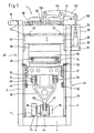
- thermoforming system 1 in a front view.
- the movable assemblies of the thermoforming unit 1 are arranged in a frame 2.
- the frame 2 can be constructed, for example, in Vorm of frame plates made of sheet steel, which are annealed stress-free.
- a bottom, that is arranged to the bottom cross member 4 connects the frame plates 2 and also serves as a bed for the bearings of the crankshaft drive 6.
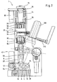
- the crankshaft drive 6 is driven in the variant shown here via an electric servo motor 8. Whose driving force is driven by a belt 10 and pulleys 12 and 14, which is particularly in Fig. 2 better visible in the lateral view.
- the crankshaft drive 6 is symmetrically mounted on both sides symmetrically in the variant shown here in relatively short lever arms 16, wherein the lever arms 16 are in turn hinged to a bearing block 18 mounted on the cross member 4.
- Fig. 1 As well as in Fig. 2
- the two-part mold 20 of the forming station of the thermoforming unit 1 is shown in the closed state.
- One in the upper part of the picture Fig. 1 and Fig. 2 recognizable Traverse 24 connects the two frame plates 2 above the two-part mold 20 and serves as the basis for a drive 26 for adjusting the upper tool table 28 with the attached upper tool 30.
- the drive 26 for adjusting the upper tool table 28 may, for example as Fine stroke be formed with threaded clearance compensation.
- a lower tool table 32 carries the lower tool 34 and is by means of appropriately designed linear guides 36 between the pivotable guide rails 38 of the pivotable guide rail assembly 40 (see. 3 and 4 ) of the guide device 42.
- Auswerferzylinder 44 and the upper connecting rod bearings 46 are attached.
- a chain transport 48 is shown, by means of which the plastic film 50 is fed to the two-part mold 20 and transported away after molding and punching the mold body not shown here, wherein the plastic film 50 preferably with appropriate means in the region of the two-part mold 20 bidirectionally planar tensioned.
- the upper tool table 28 is guided in correspondingly designed linear guides 52 between the frame plates 2.
- the lower tool 34 may for example have a mounting surface of 490 mm x 1040 mm.
- four rows of eight cavities for 32 moldings with a molding diameter of about 75 mm can be realized. This means a total punching length of all punched through edges of 7640 mm, which makes a total punching force of about 400 kN necessary.
- the upper tool 30 is attached, for example, not shown spacers on the upper tool table 28. Guide rails, not shown, facilitate the assembly of the tools.
- a thread play compensation 54 is used to compensate for game, for example, the Feinhubantrieb 26 of the upper tool table 28.
- the linear guides 36 for the lower tool table 32 have a backlash-free setting and ensure an exact guidance of the lower tool 34.
- the linear guides 52 of the upper tool table 28 have unspecified adjustable sliding guides on.
- the connecting rod 58 driven by the crankshaft drive 6, which may also be referred to as a connecting rod for the lifting drive of the lower tool table 32, is designed in the form of a triangle or Y-shaped in the variant shown here.
- the connecting rod 58 is articulated with a first connecting rod portion 60 on the eccentric shaft portion 62 of the crankshaft drive 6.
- the two in Fig. 1 and 2 upwardly facing arms 64 of the Y-shaped connecting rod 58 are hinged to the connecting rod bearings 46 of the lower tool table 32.
- These two upper connecting rod bearings 46 are here as possible arranged such that a deflection of the lower tool table 32 and its own weight can be kept as low as possible.
- the Y-shaped connecting rod 58 has at the lower connecting rod portion 60 of the variant shown here advantageously only one bearing, so that already satisfies a crank mechanism.
- crankshaft drive 6 is provided with a double bearing in a rigid construction.
- the related crank bearings may be split for ease of assembly.
- the crankshaft drive 6 is mounted centrally in lever arms 16, which form a kind of double rocker. This is in turn mounted with its right side by means of the bearing block 18 on the traverse 4.
- the punch drive 64 engages.
- the punch drive 64 consists for example of a hydraulic cylinder and an associated Hydraulic system, which generates a sudden punching stroke on the hydraulic cylinder, which is transmitted via the double rocker 16, the crankshaft drive 6, the connecting rod 58, the bearing 46 on the lower tool table 32 and thus on the lower tool 34.
- the drive of the crankshaft drive 6 can - as already mentioned above - as a lifting drive have a servo motor 8, which acts on the crankshaft drive 6 via gear, timing belt, sprocket drives or the like in low-play design.
- the closing and opening of the two-part mold 20 then corresponds to 160 ° rotation on the crankshaft.
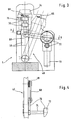
- pivot lever 38 for pivotally receiving the lower tool table 32 have in the variant shown here, for example, the closer in Fig. 3 illustrated, designed as cam rollers, pivot lever side guides 66.
- the trained example as cam rollers lateral guides 66 of the pivot lever 38 run on not shown hardened rails and are free of play adjustable for exact guidance of the lower tool 34th
- a crank rod 68 is provided on both sides of the lower tool table 32.
- drive 70 for generating the pivoting movement of the lower tool 34 via the pivotable guide rails 38 may be provided on both guide rails 38 acting Kurbelstangenschwenkantrieb 68, which is driven for example by a servo geared motor 72 and a synchronizing shaft 74.
- pivot lever stop 76 is provided, as in Fig. 3 shown. This stop 76 for the pivot lever 38 is adjustable for exact positioning of the lower tool 32.
- the drive 84 for adjusting the upper tool table 28, which may be formed, for example, as a fine drive, not only serves for example for setting the punching stroke, but can also be used to turn on or turn off the punching stroke.
- Two in Fig. 1 and 2 only slightly visible threaded spindles 78 are driven, for example via worm gear 80 via a synchronizing shaft 82 by means of a geared motor 84.
- two thread clearance compensators 54 which are designed, for example, as pneumatic bellows cylinders, can pull the upper tool table 28 upwards via tie rods, not shown, in order to eliminate the backlash between the spindle and the nut.
- a pre-stretching unit 86 has, inter alia, in the variant shown here, a pre-stretching drive 88 in the form of a servo motor, which has an infeed drive 88 in the form of a servomotor Fig. 2 Not shown toothed belt drive and planetary roller screw, the mother is connected by releasable couplings with the Vorumblerplatte 90 and the prestretchers 92 disposed thereon on. In this case, the Vortierrantrieb also have a highly dynamic servo motor 88.
- FIG. 1 illustrated alternative variant of the Vorumblerantriebs of the pre-stretching unit 86, this may have a console 94 which carries a hydraulic cylinder 96 as Vorumblerantrieb.
- the hydraulic cylinder 96 is moved with the console 94 relative to the upper tool table 28 resting with this linear. The distance between the hydraulic cylinder 96 to the upper tool table 28 thus always remains constant.
- the hydraulic cylinder 96 is encapsulated by a housing 98 so that no hydraulic oil can escape even with minor leaks.
- a push rod 100 is hinged to the hydraulic cylinder 96 as in FIG Fig. 1 shown, and is articulated with her, the hydraulic cylinder 96 facing away from the end in the right variant of a rocker arm 102 in the variant shown here.
- the rocker arm 102 is pivotally supported by means of a bearing 104.
- the bearing 104 engages on a suitable bracket in turn on the upper tool table 28.
- the pre-stretching rod 106 is articulated, which communicates with the pre-stretching plate 90 and the pre-stretchers 92 arranged thereon.
- the hydraulic cylinder 96 for driving the pre-stretchers 92 may include a servo-controller that includes a programmable controller for the stroke of the cylinder 96.
- the required hydraulic unit can be arranged in the machine base.
- the Vorierstange 106 may be connected via a compensating coupling with the Vorumblerplatte 90 in the upper tool 30.
- the housing 98 for the hydraulic cylinder 96 not only serves to catch any leaks, but can also carry the servo control and also contain sensors or the like to report any leaks occurring and have means to dissipate them. The same applies to the hydraulic lines.
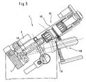
- the thermoforming plant I can be assigned a stacking device 108, which receives, stacks and removes the finished molded articles after ejection from the cavities of the lower tool 34.
- the stacking device 108 can, for example, have a rake 110 for removing the ejected molded bodies.
- FIG. 6 is another variant of the already in Fig. 1 to 5 Vorumblerantriebe 88 shown.
- a crank mechanism 140 acts via a push-pull rod 100 on a rocker arm 102, the here in Fig. 6 simplified dash-dotted line is shown to illustrate second different positions, namely the one position in the execution of the working stroke and thus lowering the Vorumbler 92 and the return stroke, ie when lifting the Vorumblerplatte 90 arranged Vorumbler 92.
- the rocker arm 102 which tilts about a pivot point in the bearing 104, which is designed to be transversely displaceable in the variant shown here, as indicated by the arrow 142, on the prestretch rod 106, which is articulated to the Vorstrekkerplatte 90.
- the stroke 146 can be varied in an advantageous manner and, in contrast, the stroke 148 of the pre-stretching drive can be kept constant.
- the downward working stroke, the pre-straightener 92 with the further arrow 150 and the relevant return stroke with the arrow 152 are marked.
- FIG. 7 is again in a simplified manner in a schematic representation of a possible embodiment of a Vorumblerantriebs 88 drive side closer shown.
- the crank mechanism 140 is supported on the housing side by means of a bearing 154.
- a transmission 156 and a clutch / brake combination 158 connect the crank drive 140 to a motor 160.
- Fig. 8 a further alternative embodiment of a Vorumblerantriebs 88 is shown in a schematically simplified sketch.
- the gearbox construction is essentially the same as in Fig. 6 discussed.
- crank mechanism 140 is in Fig. 8 a hydraulic cylinder 162 is provided, as for example in the in Fig. 1 to 5 hydraulic Vorstreckzylinder 96 discussed is the case.
- the fulcrum shift is again symbolized by the arrow 142.
- an electric motor 164 and an adjusting spindle 166 are provided.
- FIG. 9 another variant of a prestretcher drive 88 is shown schematically.
- a hydraulic pre-stretch cylinder 96 or 162 serves to generate the force.
- This is connected to the push-pull rod 100 at point A.
- the push-pull rod 100 is in turn articulated at point B on the rocker arm 102.
- the rocker arm 102 is in turn articulated at point C on the prestretch rod 106.
- the Vorchirrstange 106 in turn is at point D with the Vorrowrplatte 90 hingedly connected.
- Vorumbler 92 are hinged, which in turn are mounted linearly displaceable in the upper tool 30.
- the upper tool 30 is attached to the upper tool table 28.
- the rocker arm 102 is rotatably supported about the point B0 in the bearing 104.
- the hydraulic cylinder 96 or 162 is arranged in front of and behind the upper tool 30.
- An alternative arrangement of the cylinder 96 or 162 adjacent to the tool 30 is also possible.
- the pre-stretchers 92 are in Fig. 9 shown in the parking position. Accordingly, the pre-stretchers 92 in the schematic sketch according to Fig. 10 shown in the extended position. For the rest, the presentation is similar Fig. 10 the in Fig. 9 shown variant of an exemplary embodiment of Vorsummerantriebes 88th
- FIG. 11 another alternative embodiment of a pre-stretch drive 88 is shown.
- This is similar to the one in Fig. 9 and 10 shown variant, however, has an alternative lever mechanism.
- longitudinal holes are provided in the articulation points B and C, which allow an axial displaceability of these articulation points, so that the hydraulic cylinder 96 or 162 can be hinged directly to the rocker arm 102 at point B, so that the thrust drawbar 100 can be dispensed with.
- the Vorrowrstange 106 in which the former pivot points C and D coincide in common pivot point C, in which the rocker arm 102 is connected directly to a suitably designed shoulder or storage 168 with the Vorumble 90.
- the heated plastic film 50 is pressed into the mold cavities or cavities of the lower tool 34 with the aid of the pre-stretchers 92, which are mounted in a linearly displaceable manner in the upper tool 30, for molding the cup-shaped moldings, for example.
- the film is applied to the walls of the mold cavities or cavities.
- the Vorumbler 92 are doing again in their parking position (see. Fig. 9 ) in the upper tool 30 (see arrows 150 and 152 in FIG Fig. 6 and 8th ).
- a Vorumblerantrieb 88 is proposed with high dynamics.
- a duration of at most 300 ms, preferably at most 250 ms and particularly preferably at most 200 ms is achieved.
- the in Fig. 6 to 11 discussed Vorumblerantrieb 88 able to the pre-stretching of the plastic film 50 required forces produce.
- the sum of the forces acting on the individual Vorumbler 92 forces can be up to 50,000 N depending on the embodiment.
- a pretensioner drive 88 is provided with a hydraulic cylinder 96 or 162 for generating the necessary forces.
- the pre-stretchers 92 are in the illustrations according to Fig. 9 to 11 by means of a pre-stretching punch rod 170 with a bridge or the so-called. Vorumble 90 firmly connected.
- the stamping rods 190 run in a straight manner guided in guide bushes 172 of the upper tool 30, so that the entire pre-stretching unit 86 can be moved vertically.
- the drive of the Vorumbler 92 takes place as discussed above with the aid of the hydraulic cylinder 96 and 162 is - as in Fig. 1 to 5 shown - firmly connected to a bracket 94, which in turn is supported by the upper tool table 28.
- the linear movement of the piston rod 174 is first transmitted through the coupling or push-pull rod 100 with the pivot joints A and B on the rocker arm 102.
- the rocker arm 102 is - as discussed above - rotatably supported at the point B 0 relative to the upper tool table 28.
- the coupling or Vorumblerstange 106 with the pivot joints C and D finally transmits the movement of the rocker arm 102 to the pre-stretching unit 86th
- transmission 88 can be varied in many forms.
- the movement of the rocker arm 102 can be transmitted to the pre-stretching unit 86 by means of a bolt and a link.
- the cylinder 96 or 162 may be alternatively hinged only to the fixed connection with the bracket 94 relative to the bracket 94 and thus held pivotally.
- the present invention thus advantageously provides a thermoforming plant for the production of molded articles made of plastic film, such as cups, containers, lids, food wrappers or the like, with a forming station having a two-part mold.
- the two-part mold has an adjustably lockable upper tool table with an upper tool with pre-stretchers mounted movably therein and a movable lower tool table with a lower tool with cavities.
- the movable lower tool table is guided by means of a guide device and by a drive device relative to the upper tool table on this and movable away therefrom.
- the upper tool table has a first drive device assigned to it for setting up the upper tool table in its position relative to the top dead center of the lower tool table in coordination with the molding to be produced in each case.
- the upper tool table has a second drive device assigned to it for driving the pre-stretchers movably mounted in the upper tool.
- the present invention proposes an economical process for the production of molded plastic film.
- the thermoforming machine can be used to process plastic films made of PP, PS, PE, PET, ABS or PVC.
- the thermoforming system as a film web supplied plastic film can have a film web width of at least 250 mm to 750 mm at a film web thickness of at least 0.3 mm to 4 mm.
- the mold surface available between the upper and lower molds is at least 700 mm x 450 mm.
- the maximum closing force is at least 400 kN with a maximum cutting length of at least 8400 mm.
Abstract
Description
Die vorliegende Erfindung betrifft eine Thermoformanlage zur Herstellung von Formkörpern aus Kunststoffolie, wie Becher, Behälter, Deckel, Lebensmittelverpackungen oder dgl., mit einer ein zweiteiliges Formwerkzeug aufweisenden Umformstation, nach dem Oberbegriff des Anspruchs 1, sowie ein Verfahren zur Herstellung solcher Formkörper nach dem Oberbegriff des Anspruchs 8.The present invention relates to a thermoforming plant for the production of moldings of plastic film, such as cups, containers, lids, food packaging or the like., With a two-part mold having forming station, according to the preamble of
Thermoformanlagen sind in unterschiedlichen Varianten und Ausführungsformen in der Praxis bekannt geworden. Dabei wird zur Herstellung behälterförmiger Artikel bzw. Formkörper aus thermoplastischem Kunststoff ein zweiteiliges Formwerkzeug verwendet. Eine Formhälfte, das sogenannte obere Werkzeug, ist am oberen Werkzeugtisch befestigt und mit diesem in der Regel einstellbar feststellbar mit dem Rahmen bzw. Gestell der Thermoformanlage verbunden, so daß das obere Werkzeug auf den jeweils herzustellenden Formkörper eingestellt werden kann. Die andere Formhälfte, das sogenannte untere Werkzeug, ist beweglich im Rahmen bzw. Gestell der Thermoformanlage geführt.Thermoforming plants have become known in various variants and embodiments in practice. In this case, a two-part mold is used to produce container-shaped article or molded body made of thermoplastic material. A mold half, the so-called upper tool, is attached to the upper tool table and connected to this adjustable adjustable feststellbar usually connected to the frame or frame of the thermoforming system, so that the upper tool can be adjusted to the moldings to be produced in each case. The other mold half, the so-called lower tool, is movably guided in the frame or frame of the thermoforming system.
Zum Ausformen der Formkörper befinden sich die Formhälften, also das obere und das untere Werkzeug, in einer einander zugewandten geschlossenen Position. Zwischen dem oberen und dem unteren Werkzeug ist eine häufig vorgewärmte und somit gut plastisch verformbare Kunststoffolie angeordnet, welche meistens in Form einer Folienbahn von einer Vorratsrolle taktweise zugeführt wird.To mold the moldings are the mold halves, so the upper and the lower tool, in a mutually facing closed position. Between the upper and the lower tool, a frequently preheated and thus readily plastically deformable plastic film is arranged, which is supplied in cycles in the form of a film web from a supply roll cyclically.
Beim Tiefziehvorgang wird die Kunststoffolie zwischen dem oberen und dem unteren Werkzeug eingeklemmt und damit in dessen Lage fixiert. Dann wird die Kunststoffolie durch die Vorstrecker des oberen Werkzeugs in die Kavitäten des unteren Werkzeugs gedrückt, während der Rand des zu erzeugenden Formkörpers weiterhin zwischen dem oberen und dem unteren Werkzeug klemmend festgehalten ist. Durch Erzeugung eines Unterdrucks in den Kavitäten oder durch Einblasen von Luft legt sich die Folie an die Innenwandungen der Kavitäten im unteren Werkzeug an und nimmt somit die gewünschte Form an.During the deep-drawing process, the plastic film is clamped between the upper and the lower tool and thus fixed in its position. Then, the plastic film is pressed by the pre-stretchers of the upper tool in the cavities of the lower tool, while the edge of the molded body to be generated is still clamped between the upper and the lower tool. By generating a negative pressure in the cavities or by blowing in air, the film applies to the inner walls of the cavities in the lower tool and thus assumes the desired shape.
Nach hinreichender Abkühlung der Kunststoffolie durch den Kontakt mit der ggf. aktiv gekühlten Werkzeugoberfläche erfolgt das Heraustrennen der Formkörper aus der Kunststoffolie. Hierzu wird das untere Werkzeug etwa um den Betrag der Foliendicke aufwärts bewegt. Entsprechende Schneidkanten des zweiteiligen Formwerkzeugs schneiden dabei die einzelnen Formkörper aus der Folienbahn heraus. Das zurückbleibende Foliengitter wird häufig wiederum taktweise einer Aufwickeleinheit zugeführt.After sufficient cooling of the plastic film by the contact with the possibly actively cooled tool surface, the separation of the shaped body from the plastic film takes place. For this purpose, the lower tool is moved upwards by about the amount of the film thickness. Corresponding cutting edges of the two-part mold thereby cut out the individual moldings from the film web. The remaining foil grid is often fed in turn cyclically to a take-up unit.
Zur Entnahme der Formkörper aus den Kavitäten wird das untere Werkzeug anschließend vom oberen Werkzeug weg bewegt und dabei derart um dessen Längsachse verschwenkt, daß das untere Werkzeug zu einer Stapeleinrichtung zeigt und damit die Formkörper der Stapeleinrichtung übergeben werden können.For removal of the molded body from the cavities, the lower tool is then moved away from the upper tool and thereby pivoted about its longitudinal axis, that the lower tool points to a stacking device and thus the shaped body of the stacking device can be transferred.
Beispiele für vorstehend diskutierte, aus der Praxis bekannte Thermoformanlagen sind z.B. in der
Diese bekannten Thermoformanlagen weisen jedoch den wesentlichen wirtschaftlichen Nachteil auf, daß damit lediglich geringe Taktfrequenzen beispielsweise bis etwa 30 Takte pro Minute realisierbar sind. Höhere Taktfrequenzen sind ohne Beschädigung der bewegten Bauteile nicht möglich. Diese geringen Taktfrequenzen sind jedoch angesichts des heute vorherrschenden hohen Kostendrucks nicht mehr akzeptabel.However, these known thermoforming systems have the significant economic disadvantage that only low clock frequencies, for example, up to about 30 cycles per minute can be realized. Higher clock frequencies are not possible without damaging the moving components. However, these low clock rates are no longer acceptable in the face of today's high cost pressures.
Weiterhin von Nachteil sind die bei den bekannten Thermoformanlagen eingesetzten Antriebe für die im oberen Werkzeug beweglich angeordneten Vorstrecker, da mit diesen ebenfalls lediglich geringe Taktfrequenzen beispielsweise bis etwa 30 Takte pro Minute realisierbar sind. Ferner ist bei den bekannten Thermoformanlagen die mangelnde Genauigkeit bei der Einstellbarkeit bzw. Anpassbarkeit des oberen Werkzeugs in Bezug auf die herzustellenden Formkörper von Nachteil.Another disadvantage is the drives used in the known thermoforming systems for the upper tool movably arranged pre-stretchers, as with these also only low clock frequencies, for example, to about 30 cycles per minute can be realized. Furthermore, in the known thermoforming plants the lack of accuracy in the adjustability or adaptability of the upper tool with respect to the molded body to be disadvantageous.
Die in der
Die bei der aus der
Nähere Informationen zur Ausgestaltung des Antriebs der Vorstrecker sind der
Die Thermoformanlage gemäß der
Abgesehen davon sind mit den geometrisch komplexen und nur sehr schwer aufeinander abstimmbaren Nutkurvenführungen die heute geforderten hohen Taktfrequenzen ausgeschlossen.Apart from that, today's demanded high clock frequencies are impossible with the geometrically complex and very difficult to tune Nutkurvenführungen.
Der Antrieb der Vorstrecker ist bei der
Daneben sind aus der Praxis Vorstreckerantriebe bekannt geworden, bei denen die Vorstrecker vermittels Kugelrollenspindeln angetrieben werden. Mit derartigen Kugelrollenspindeln sind die geforderten hohen Taktfrequenzen nicht zu erreichen. Darüber hinaus sind Kugelrollenspindeln zu teuer, wartungsanfällig und weisen als weiteren Nachteil hohe Ausfallzeiten auf.In addition, Vorstreckerantriebe have become known in practice, in which the pre-stretchers are driven by means of ball roller spindles. With such ball roller spindles, the required high clock frequencies can not be achieved. In addition, ball roller spindles are too expensive, maintenance-prone and have as a further disadvantage high downtime.
Eine weitere gattungsgemäße Thermoformanlage nach dem Oberbegriff der unabhängigen Ansprüche ist Gegenstand der
Ausgehend vom Stand der Technik ist es Aufgabe der vorliegenden Erfindung, bekannte Thermoformanlagen derart zu verbessern, daß wesentlich höhere Taktfrequenzen erreicht werden können und damit ein wirtschaftlicher Betrieb solchermaßen verbesserter Thermoformanlagen möglich wird. Ferner ist es Aufgabe der vorliegenden Erfindung, ein wirtschaftliches Verfahren zur Herstellung von Formkörpern aus Kunststoffolie vorzuschlagen.Starting from the prior art, it is an object of the present invention to improve known thermoforming systems such that significantly higher clock frequencies can be achieved and thus an economic operation of such improved thermoforming equipment is possible. Furthermore, it is an object of the present invention to propose an economical process for the production of molded articles from plastic film.
Diese Aufgabe wird in vorrichtungstechnischer Hinsicht durch die Merkmale des Anspruchs 1 gelöst.This object is achieved in device-technical terms by the features of
In verfahrenstechnischer Hinsicht wird die Aufgabe gelöst durch die Merkmale des Anspruchs 8.In procedural terms, the object is achieved by the features of
Weitere vorteilhafte Ausführungsformen und Aspekte der vorliegenden Erfindung sind Gegenstand der Unteransprüche.Further advantageous embodiments and aspects of the present invention are the subject of the dependent claims.
Erfindungsgemäß wird eine Thermoformanlage zur Herstellung von Formkörpern aus Kunststoffolie, wie Becher, Behälter, Deckel, Lebensmittelverpackungen oder dgl., mit einer ein zweiteiliges Formwerkzeug aufweisenden Umformstation, vorgeschlagen. Dabei weist das zweiteilige Formwerkzeug einen einstellbar feststellbar oberen Werkzeugtisch mit einem oberen Werkzeug mit darin beweglich gelagerten Vorstreckern und einen beweglichen unteren Werkzeugtisch mit einem unteren Werkzeug mit Kavitäten auf. Der bewegliche untere Werkzeugtisch ist dabei vermittels einer Führungseinrichtung geführt und durch eine Antriebseinrichtung relativ zum oberen Werkzeugtisch auf diesen zu und von diesem weg bewegbar.According to the invention, a thermoforming plant for the production of molded articles from plastic film, such as cups, containers, lids, food packaging or the like, with a two-part mold having forming station proposed. In this case, the two-part mold has an adjustable ascertainable upper tool table with an upper tool with movably mounted pre-stretchers and a movable lower tool table with a lower tool with cavities. The movable lower tool table is guided by means of a guide device and by a drive device relative to the upper tool table on this and movable away therefrom.
Hierbei ist vorgesehen, daß der obere Werkzeugtisch eine erste ihm zugeordnete Antriebseinrichtung zum Einrichten des oberen Werkzeugtisches in seiner Lage relativ zum oberen Totpunkt des unteren Werkzeugtisches in Abstimmung mit dem jeweils herzustellenden Formkörper aufweist, und daß der obere Werkzeugtisch eine zweite ihm zugeordnete Antriebseinrichtung zum Antreiben der im oberen Werkzeug beweglich gelagerten Vorstrecker aufweist.It is provided that the upper tool table has a first associated with him drive means for setting up the upper tool table in position relative to the top dead center of the lower tool table in coordination with each mold to be produced, and that the upper tool table a second associated drive device for driving the having in the upper tool movably mounted pre-stretchers.
Die erfindungsgemäße Entkoppelung des Antriebs der Vorstrecker durch eine entsprechende Bereitstellung eines hierfür separaten Antriebs als auch eines weiteren separaten Antriebs zum Justieren bzw. Einstellen des oberen Werkzeugs bietet, in Bezug auf die herzustellenden Formkörper vor dessen abschließender Feststellung vor dem Starten des jeweiligen Produktionsprozesses, den Vorteil, daß diese beiden Antriebe unabhängig voneinander optimiert werden können. Dementsprechend kann ein für das einmalige Justieren bzw. Einstellen des oberen Werkzeuges vor Beginn des jeweiligen Produktionsprozesses bestgeeigneter Antrieb vorgesehen werden, der dann in vorteilhafter Weise nicht zwingend zugleich auch noch die geforderten hohen Taktfrequenzen beim Antreiben des Vorstreckers realisieren muß, sondern speziell bezüglich Genauigkeit und Wiederholbarkeit einer exakten Justierung des oberen Werkzeugtisches ausgewählt werden kann. Dementsprechend kann der separate Vorstreckerantrieb in Bezug auf die geforderte hohe Taktfrequenz ausgewählt und diesbezüglich optimiert werden.The inventive decoupling of the drive of the pre-stretchers by a corresponding provision of a separate drive for this purpose as well as another separate drive for adjusting or adjusting the upper tool offers, with respect to the moldings to be produced before its final determination before starting the respective production process, the advantage that these two drives can be optimized independently. Accordingly, a best suited for the single adjustment or setting of the upper tool before the beginning of the respective production process drive can be provided, which then necessarily not necessarily at the same time still need to realize the required high clock frequencies when driving the pre-stretchers, but especially in terms of accuracy and repeatability a precise adjustment of the upper tool table can be selected. Accordingly, the separate Vorstreckerantrieb can be selected in relation to the required high clock frequency and optimized in this regard.
Eine derartige separate Optimierung der getrennten Antriebe erhöht zwar augenscheinlich die Anzahl der Bauteile, bietet demgegenüber jedoch den unschätzbaren Vorteil, daß beide Antriebe für sich konstruktiv möglichst einfach gehalten und damit schlußendlich wieder kostengünstig ausgebildet werden können.Although such a separate optimization of the separate drives apparently increases the number of components, on the other hand, however, offers the invaluable advantage that both drives can be constructively kept as simple as possible and thus ultimately can be formed inexpensively.
In einer Ausführungsform der Thermoformanlage ist die erste Antriebseinrichtung zum Einrichten des oberen Werkzeugtisches als elektrischer Servomotor ausgebildet. Dieser bietet den Vorteil einer exakten Regelbarkeit, wobei dessen Geschwindigkeitsprofil frei wählbar ist. Damit können sowohl schnelle Zustellbewegungen zur Überwindung großer Einstellwege als auch besonders langsame und genaue Zustellbewegungen für ein exaktes Einrichten des oberen Werkzeugtisches im Millimeter- oder gar Zehntelmillimeterbereich je nach gewünschter Genauigkeit erreicht werden. Zudem stehen elektrische Servomotoren in jeder geforderten Auslegungsvariante kostengünstig am Markt zur Verfiigung.In one embodiment of the thermoforming system, the first drive device for setting up the upper tool table is designed as an electric servomotor. This offers the advantage of exact controllability, with its speed profile is freely selectable. Thus, both fast feed movements to overcome large adjustment paths as well as particularly slow and accurate feed movements for an exact setting up of the upper tool table in the millimeter or even tenths of a millimeter range can be achieved depending on the desired accuracy. In addition, electric servomotors are available on the market at low cost in every required design variant.
Gemäß einer weiteren Ausführungsform der Thermoformanlage ist vorgesehen, daß diese erste Antriebseinrichtung über eine Synchronisationswelle mit darauf beispielsweise angeordneten Schnecken/Rädern über zwei zugeordnete Stellspindeln zusammenwirkt, die ihrerseits derart auf den oberen Werkzeugtisch einwirken, daß dieser in seiner horizontalen Ausrichtung vertikal auf und ab bewegbar ist, so daß der obere Werkzeugtisch auf den jeweils herzustellenden Formkörper einstellbar ist. Damit kann ein frei wählbares Geschwindigkeitsprofil eines Servomotors in synergetischer Weise optimal sowohl in große Zustellbewegungen als auch in kleine bzw. feine Justierbewegungen übersetzt werden.According to a further embodiment of the thermoforming system is provided that this first drive means via a synchronization shaft arranged thereon, for example, arranged worms / wheels via two associated adjusting spindles, which in turn act on the upper tool table, that this in its horizontal orientation is vertically movable up and down, so that the upper tool table is adjustable to each mold to be produced. Thus, a freely selectable velocity profile of a servomotor can be translated in a synergistic manner optimally both in large advancing movements and in small or fine adjustment movements.
Bei einer weiteren Ausführungsform der erfindungsgemäßen Thermoformanlage weist die zweite Antriebseinrichtung des oberen Werkzeugtisches zum Antreiben der Vorstrecker einen hydraulischen Antrieb oder einen vermittels eines elektrischen Servomotors angetriebenen Kurbelantrieb auf. In beiden Fällen sind besonders hohe Taktfrequenzen erzielbar. Diese hohen Taktfrequenzen können wenigstens 40 Takt, 50 Takte oder mehr Takte betragen. So können darüber hinaus bei einem hydraulischen Antrieb der Vorstrecker in vorteilhafter Weise Vorstreckerkräfte von wenigstens 40 kN bei einem Arbeitshub von wenigstens 120 mm und einer bewegten Masse von wenigstens 200 kg realisiert werden, wobei die Zeit für das Überstreichen des Arbeitshubes von 120 mm weniger als 200 ms beträgt.In a further embodiment of the thermoforming system according to the invention, the second drive device of the upper tool table for driving the pre-stretchers has a hydraulic drive or a crank drive driven by means of an electric servomotor. In both cases, particularly high clock frequencies can be achieved. These high clock frequencies may be at least 40 clocks, 50 clocks or more clocks. Thus, in a hydraulic drive of the pre-stretchers advantageously Vorvorreckerkräfte of at least 40 kN at a working stroke of at least 120 mm and a moving mass of at least 200 kg can be realized, the time for sweeping the working stroke of 120 mm less than 200 ms is.
Entsprechend einer weiter bevorzugten Variante der zweiten Antriebseinrichtung wirkt diese über eine Schubstange, einen Kipphebel und eine Druckstange auf den Vorstrecker im oberen Werkzeug ein, was eine besonders einfache konstruktive Lösung darstellt. Dabei ist in besonders bevorzugter Weise vorgesehen, daß der Kipphebel einen verschieblich ausgestalteten Drehpunkt aufweist, so daß dessen Hebelarme und damit einhergehend dessen Kraftverhältnisse auf den jeweiligen Anwendungsfall abgestimmt werden können. Die Betätigung der Vorstrecker über eine Schubstange, einen Kipphebel und eine Druckstange ermöglicht die Anordnung des zweiten Antriebs außerhalb des Bereiches des oberen Werkzeuges insbesondere in vorteilhafter Weise nicht direkt über diesem, so daß bei Einsatz eines hydraulischen Antriebes ein nicht immer gänzlich auszuschließendes geringfügiges Austreten von Hydrauliköl nicht weiter von Bedeutung ist, da dieses in vorteilhafter Weise nicht auf die Folienbahn hinunter tropfen kann. Zudem kann in weiter vorteilhafter Weise der zweite Antrieb für die Vorstrecker bei Übertragung dessen Antriebskräfte über eine Schubstange, einen Kipphebel und eine Druckstange auf die Vorstrecker derart seitlich vom oberen Werkzeugtisch angeordnet werden, daß sich der zweite Antrieb mit dem oberen Werkzeugtisch mit diesem mit und somit relativ zu diesem nicht bewegt, so daß der zweite Antrieb ausschließlich die Bewegung der Vorstrecker steuert und somit besonders vorteilhaft in Bezug auf hohe Taktfrequenzen optimiert werden kann.According to a further preferred variant of the second drive device, this acts via a push rod, a rocker arm and a push rod on the pre-stretchers in the upper tool, which represents a particularly simple design solution. It is provided in a particularly preferred manner that the rocker arm has a displaceably configured pivot point, so that its lever arms and, consequently, its force relationships can be adapted to the particular application. The operation of the pre-stretchers via a push rod, a rocker arm and a push rod allows the arrangement of the second drive outside of the Area of the upper tool, in particular advantageously not directly above this, so that when using a hydraulic drive not always completely excluded minor leakage of hydraulic oil is not of much importance, since this can not drip down on the film web in an advantageous manner. In addition, in a further advantageous manner, the second drive for the pre-stretchers in transferring its driving forces via a push rod, a rocker arm and a push rod on the pre-stretchers are arranged laterally from the upper tool table, that the second drive with the upper tool table with this and thus is not moved relative to this, so that the second drive controls only the movement of the pre-straightener and thus can be optimized particularly advantageous with respect to high clock frequencies.
Weiter von Vorteil ist, daß die Verschiebung des Drehpunktes zur Einstellung eines variablen Vorstreckerhubes nutzbar ist. Die Drehpunktverschiebung ergibt in vorteilhafter Weise einen konstanten Hub des Antriebes und eine stufenlose Anpassung des Vorstreckerhubes, so daß der obere Totpunkt des Vorstreckers konstant bleibt und der untere Totpunkt je nach Produkt- bzw. Formkörperhöhe angepaßt werden kann.Another advantage is that the displacement of the pivot point for setting a variable Vorstreckerhubes is available. The fulcrum displacement advantageously results in a constant stroke of the drive and a stepless adjustment of Vorstreckerhubes, so that the top dead center of the pre-stretchers remains constant and the bottom dead center can be adjusted depending on product or molded body height.
Bei einer weiteren Ausführungsform der erfindungsgemäßen Thermoformanlage ist der Vorstrecker vermittels der zweiten Antriebsvorrichtung derart antreibbar, daß ein Hub von wenigstens 120 mm oder mehr in weniger als 300 ms, vorzugsweise weniger als 200 ms, ausführbar ist. Damit werden vorteilhafter Weise Taktfrequenzen über 60 Takte pro Minute realisierbar, so daß bei einer erfindungsgemäßen Thermoformanlage, die beispielsweise einen Kurbelantrieb für einen linear geführten unteren Werkzeugtisch vorsieht, insgesamt bislang nicht als realisierbar geglaubte hohe Taktfrequenzen erreicht werden können.In a further embodiment of the thermoforming system according to the invention, the pre-straightener is drivable by means of the second drive device such that a stroke of at least 120 mm or more in less than 300 ms, preferably less than 200 ms, is executable. This advantageously clock frequencies over 60 cycles per minute can be realized, so that in a thermoforming system according to the invention, which provides, for example, a crank drive for a linear guided lower tool table, total so far not as feasible believed high clock frequencies can be achieved.
Die vorstehende Aufgabe wird in verfahrenstechnischer Hinsicht durch die Merkmale des Anspruchs 8 gelöst.The above object is achieved in procedural terms by the features of
Die Erfindung wird nachfolgend in Ausführungsbeispielen anhand der Figuren der Zeichnung näher erläutert. Es zeigt:
- Fig. 1
- eine Draufsicht auf eine Ausführungsform einer Thermoformanlage;
- Fig. 2
- eine Seitenansicht der in
Fig. 1 dargestellten beispielhaften Ausführungsform einer Thermoformanlage; - Fig. 3
- eine von der Seite gezeigte Detailansicht des Antriebs zum Verschwenken der Führungs-Schienenanordnung der in
Fig. 1 und2 gezeigten Variante einer Thermoformanlage; - Fig. 4
- einen Schnitt längs der Linie X-X aus
Fig. 3 ; - Fig. 5
- die in
Fig. 1 gezeigte Variante in einer schräggestellten Betriebsanordnung;bis 4 - Fig. 6
- eine schematisch vereinfachte Skizze einer beispielhaften Ausführungsform eines Antriebs zur Betätigung der Vorstrecker in der Thermoformanlage gemäß
Fig. 1 bis 5 ; - Fig.7
- eine schematisch vereinfachte Skizze einer beispielhaften Ausführungsform, die verdeutlicht, wie der in
Fig. 6 gezeigte Antrieb ausgebildet sein kann; - Fig. 8
- eine alternative Ausführungsform des Vorstreckerantriebs der Thermoformanlage gemäße
Fig. 1 bis 5 ; - Fig. 9
- eine weitere Variante der in
Fig. 6 gezeigten Alternativen Vorstreckerantriebe, mit den Vorstreckern in der Parkposition;bis 8 - Fig. 10
- die in
Fig. 9 gezeigte Ausführungsform eines Vorstreckerantriebes, mit den Vorstreckern in ausgefahrenem Zustand; und - Fig. 11
- eine weitere alternative Getriebestruktur zu den in
Fig. 6 gezeigten Varianten von Vorstreckerantrieben.bis 10
- Fig. 1
- a plan view of an embodiment of a thermoforming plant;
- Fig. 2
- a side view of in
Fig. 1 illustrated exemplary embodiment of a thermoforming system; - Fig. 3
- a side view of the drive shown for pivoting the guide rail assembly shown in FIG
Fig. 1 and2 shown variant of a thermoforming system; - Fig. 4
- a section along the line XX
Fig. 3 ; - Fig. 5
- in the
Fig. 1 to 4 shown variant in a tilted operating arrangement; - Fig. 6
- a schematically simplified sketch of an exemplary embodiment of a drive for actuating the Vorstrecker in the thermoforming system according to
Fig. 1 to 5 ; - Figure 7
- a schematically simplified sketch of an exemplary embodiment, which illustrates how the in
Fig. 6 shown drive can be formed; - Fig. 8
- an alternative embodiment of the Vorstreckerantriebs the thermoforming plant according
Fig. 1 to 5 ; - Fig. 9
- another variant of in
Fig. 6 to 8 shown alternatives Vorstreckerantriebe, with the Vorstreckern in the parking position; - Fig. 10
- in the
Fig. 9 shown embodiment of a Vorstreckerantriebes, with the pre-stretchers in the extended state; and - Fig. 11
- another alternative transmission structure to the in
Fig. 6 to 10 shown variants of Vorstreckerantrieben.
In
In
Zwischen dem oberen Werkzeug 30 und dem unteren Werkzeug 34 des in
Der obere Werkzeugtisch 28 ist in entsprechend ausgestalteten Linearführungen 52 zwischen den Gestellplatten 2 geführt. Das untere Werkzeug 34 kann beispielsweise eine Anschraubfläche von 490 mm x 1040 mm haben. Damit sind beispielsweise vier Reihen à acht Kavitäten für 32 Formkörper bei einem Formkörperdurchmesser von etwa 75 mm realisierbar. Dies bedeutet eine gesamte Stanzlänge aller durchzustanzenden Kanten von 7640 mm, was eine Gesamtstanzkraft von etwa 400 kN notwendig macht.The upper tool table 28 is guided in correspondingly designed
Das obere Werkzeug 30 ist beispielsweise über nicht näher dargestellte Distanzstücke am oberen Werkzeugtisch 28 befestigt. Nicht näher dargestellte Führungsschienen erleichtern die Montage der Werkzeuge. Ein Gewindespielausgleich 54 dient zum Ausgleich von Spiel beispielsweise beim Feinhubantrieb 26 des oberen Werkzeugtisches 28. Die Linearführungen 36 für den unteren Werkzeugtisch 32 weisen eine spielfreie Einstellung auf und gewährleisten eine exakte Führung des unteren Werkzeuges 34. Die Linearführungen 52 des oberen Werkzeugtisches 28 weisen nicht näher dargestellte spielfrei einstellbare Gleitführungen auf.The
Die unterhalb des unteren Werkzeugtisches 32 angeordneten Auswerferantriebe 44 für die in
Die vom Kurbelwellenantrieb 6 angetriebene Pleuelstange 58, die auch als Kurbelstange für den Hubantrieb des unteren Werkzeugtisches 32 bezeichnet werden kann, ist in der hier dargestellten Variante in Form eines Dreiecks bzw. Y-förmig ausgebildet. Die Pleuelstange 58 ist mit einem ersten Pleuelstangenabschnitt 60 am Exzenterwellenabschnitt 62 des Kurbelwellenantriebs 6 angelenkt. Die beiden in
Wie bereits vorstehend ausgeführt ist der Kurbelwellenantrieb 6 mit einer zweifachen Lagerung in biegesteifer Ausführung vorhanden. Die diesbezüglichen Kurbellager können zum Zwecke einer leichten Montage geteilt sein. Der Kurbelwellenantrieb 6 ist mittig in Hebelarmen 16 gelagert, die eine Art Doppelschwinge ausbilden. Diese ist ihrerseits mit deren rechter Seite vermittels des Lagerbocks 18 auf der Traverse 4 gelagert. An der linken Seite dieser Doppelschwinge greift der Stanzantrieb 64 an. Der Stanzantrieb 64 besteht beispielsweise aus einem Hydraulikzylinder und einer zugeordneten Hydraulikanlage, die über den Hydraulikzylinder einen schlagartigen Stanzhub erzeugt, welcher über die Doppelschwinge 16, den Kurbelwellenantrieb 6, die Pleuelstange 58, die Lager 46 auf den unteren Werkzeugtisch 32 und damit auf das untere Werkzeug 34 übertragen wird.As already stated above, the
Der Antrieb des Kurbelwellenantriebs 6 kann - wie bereits vorstehend erwähnt - als Hubantrieb einen Servomotor 8 aufweisen, der über Getriebe, Zahnriemen, Zahnkettentriebe oder dergleichen in spielarmer Ausführung auf den Kurbelwellenantrieb 6 einwirkt. Das Schließen und das Öffnen des zweiteiligen Formwerkzeuges 20 entspricht dann je 160° Umdrehung an der Kurbelwelle.The drive of the
Die bereits in
Als Antrieb zum Verschwenken der schwenkbaren Führungsschienen 38 der verschwenkbaren Führungs-Schienenanordnung 40 ist beidseitig des unteren Werkzeugtisches 32 eine Kurbelstange 68 vorgesehen. Als Antrieb 70 zur Erzeugung der Schwenkbewegung des unteren Werkzeuges 34 über die schwenkbaren Führungsschienen 38 kann ein auf beide Führungsschienen 38 einwirkender Kurbelstangenschwenkantrieb 68 vorgesehen sein, der beispielsweise durch einen Servo-Getriebemotor 72 und eine Gleichlaufwelle 74 angetrieben wird. Diese Details sind in
Zur Begrenzung der Schwenkbewegung in den Rahmen bzw. das Gestell 2 hinein ist ein Schwenkhebelanschlag 76 vorgesehen, wie in
Der Antrieb 84 zur Einstellung des oberen Werkzeugtisches 28, der beispielsweise als Feinantrieb ausgebildet sein kann, dient nicht nur beispielsweise zur Einstellung des Stanzhubes, sondern kann auch zur Einschaltung oder Ausschaltung des Stanzhubes herangezogen werden. Zwei in
In der hier dargestellten Variante gemäß
Wie in
In der in
Wie in
Die in vorstehender Diskussion der
In
In
In
In
Bei dem in
In
Wie vorstehend bereits diskutiert wird zum Formen der beispielsweise becherförmigen Formkörper die erwärmte Kunststoffolie 50 mit Hilfe der im oberen Werkzeug 30 geradlinig verschieblich gelagerten Vorstrecker 92 in die Formnester bzw. Kavitäten des unteren Werkzeuges 34 gedrückt. Durch Erzeugung beispielsweise eines Überdrucks im oberen Werkzeug 30 legt sich die Folie an die Wandungen der Formnester bzw. Kavitäten an. Die Vorstrecker 92 werden dabei wieder in ihre Parkstellung (vgl.
Um möglichst kurze Zeiten für das Formen der Formkörper zu erreichen, ist ein Vorstreckerantrieb 88 mit hoher Dynamik vorgeschlagen. Für einen Bewegungszyklus der Vorstrecker 92 (Abwärtsbewegung 150 und Rückbewegung 153 in die Ausgangsposition) wird eine Dauer von höchstens 300 ms, vorzugsweise höchstens 250 ms und besonders bevorzugt höchstens 200 ms erzielt. Zudem ist der in
Dementsprechend ist die vorstehend diskutierte Ausführungsform eines Vorstreckerantriebes 88 mit einem hydraulischen Zylinder 96 bzw. 162 zur Erzeugung der notwendigen Kräfte vorgesehen. Die Vorstrecker 92 sind in den Darstellungen gemäß
Der Antrieb der Vorstrecker 92 erfolgt wie vorstehend diskutiert mit Hilfe des Hydraulikzylinders 96 bzw. 162 ist - wie in
Das in
Ein weiterer Vorteil des hydraulischen Vorstreckerantriebs 88 sind die damit erzeugbaren hohen Kräfte bei einer sehr guten Dynamik. Die Gefahr einer thermischen Überlastung besteht hierbei nicht.Another advantage of the
Die vorliegende Erfindung schafft damit in vorteilhafter Weise eine Thermoformanlage zur Herstellung von Formkörpern aus Kunststoffolie, wie Becher, Behälter, Deckel, Lebensmittelumverpackungen oder dergleichen, mit einer ein zweiteiliges Formwerkzeug aufweisenden Umformstation. Das zweiteilige Formwerkzeug weist einen einstellbar feststellbaren oberen Werkzeugtisch mit einem oberen Werkzeug mit darin beweglich gelagerten Vorstreckern und einen beweglichen unteren Werkzeugtisch mit einem unteren Werkzeug mit Kavitäten auf. Der bewegliche untere Werkzeugtisch ist vermittels einer Führungseinrichtung geführt und durch eine Antriebseinrichtung relativ zum oberen Werkzeugtisch auf diesen zu und von diesem weg bewegbar. Hierbei weist der obere Werkzeugtisch eine erste ihm zugeordnete Antriebseinrichtung zum Einrichten des oberen Werkzeugtisches in seiner Lage relativ zum oberen Totpunkt des unteren Werkzeugtisches in Abstimmung mit dem jeweils herzustellenden Formkörper auf. Weiterhin weist der obere Werkzeugtisch eine zweite ihm zugeordnete Antriebseinrichtung zum Antreiben der im oberen Werkzeug beweglich gelagerten Vorstrecker auf. Ferner schlägt die vorliegende Erfindung eine wirtschaftliches Verfahren zur Herstellung der Formkörper aus Kunststoffolie vor.The present invention thus advantageously provides a thermoforming plant for the production of molded articles made of plastic film, such as cups, containers, lids, food wrappers or the like, with a forming station having a two-part mold. The two-part mold has an adjustably lockable upper tool table with an upper tool with pre-stretchers mounted movably therein and a movable lower tool table with a lower tool with cavities. The movable lower tool table is guided by means of a guide device and by a drive device relative to the upper tool table on this and movable away therefrom. In this case, the upper tool table has a first drive device assigned to it for setting up the upper tool table in its position relative to the top dead center of the lower tool table in coordination with the molding to be produced in each case. Furthermore, the upper tool table has a second drive device assigned to it for driving the pre-stretchers movably mounted in the upper tool. Furthermore, the present invention proposes an economical process for the production of molded plastic film.
Sofern ein hydraulischer Antrieb für die Vorstrecker vorgesehen ist, kann dieser in vorteilhafter Weise als sog. Linearverstärker Servosteuerung vorgesehen werden, so daß sowohl dessen Hub als auch Geschwindigkeitsprofil unabhängig voneinander gesteuert und damit vorgegeben werden können.If a hydraulic drive is provided for the pre-stretchers, this can be provided in an advantageous manner as so-called. Linear amplifier servo control, so that both its stroke and speed profile can be independently controlled and thus specified.
Mit der Thermoformanlage können Kunststoffolien aus PP, PS, PE, PET, ABS oder PVC verarbeitet werden. Die der Thermoformanlage als Folienbahn zugeführte Kunststoffolie kann dabei eine Folienbahnbreite von wenigstens 250 mm bis 750 mm bei einer Folienbahndicke von wenigstens 0,3 mm bis 4 mm aufweisen. Die zwischen dem oberen und dem unteren Werkzeug verfügbare Formfläche beträgt wenigstens 700 mm x 450 mm. Die maximale Schließkraft beträgt wenigstens 400 kN bei einer maximalen Schnittlänge von wenigstens 8400 mm.The thermoforming machine can be used to process plastic films made of PP, PS, PE, PET, ABS or PVC. The thermoforming system as a film web supplied plastic film can have a film web width of at least 250 mm to 750 mm at a film web thickness of at least 0.3 mm to 4 mm. The mold surface available between the upper and lower molds is at least 700 mm x 450 mm. The maximum closing force is at least 400 kN with a maximum cutting length of at least 8400 mm.
- 11
- ThermoformanlageThermoforming system
- 22
- Gestell bzw. RahmenFrame or frame
- 44
- untere Traverselower crossbar
- 66
- Kurbelwellenantriebcrankshaft drive
- 88th
- elektrischer Servomotorelectric servomotor
- 1010
- Riemenbelt
- 1212
- Riemenscheibepulley
- 1414
- Riemenscheibepulley
- 1616
- Hebelarmlever arm
- 1818
- Lagerbockbearing block
- 2020
- zweiteiliges Formwerkzeugtwo-piece mold
- 2222
- 2424
- obere Traverseupper crossbar
- 2626
- Antriebeinstellung oberes WerkzeugDrive adjustment upper tool
- 2828
- oberer Werkzeugtischupper tool table
- 3030
- oberes Werkzeugupper tool
- 3232
- unterer Werkzeugtischlower tool table
- 3434
- unteres Werkzeuglower tool
- 3636
- Linearführung unterer WerkzeugtischLinear guide lower tool table
- 3838
- schwenkbare Führungsschienenswiveling guide rails
- 4040
- Führungs-SchienenanordnungGuide rail assembly
- 4242
- Führungseinrichtungguide means
- 4444
- Auswerferantriebejector
- 4646
- Pleuelstangenlagerconnecting rod bearing
- 4848
- Kettentransportchain transport
- 5050
- Kunststoffolieplastic film
- 5252
- Linearführung oberer WerkzeugtischLinear guide upper tool table
- 5454
- Gewinde-SpielausgleichThread-lash adjuster
- 5656
- Auswerferejector
- 5858
- Pleuelstangeconnecting rod
- 6060
- erster Pleuelstangenabschnittfirst connecting rod section
- 6262
- Exzenterwellenabschnitteccentric shaft
- 6464
- Stanzantriebpunch drive
- 6666
- Schwenkhebel-SeitenführungSwing handle cornering
- 6868
- KurbelstangenschwenkantriebConnecting rod pivot drive
- 7070
- SchwenkantriebRotary actuator
- 7272
- Servo-GetriebemotorServo gearmotor
- 7474
- GleichlaufwelleSynchronizing shaft
- 7676
- Schwenkhebel-AnschlagSwivel bar stop
- 7878
- Gewindespindelscrew
- 8080
- Schneckengetriebeworm gear
- 8282
- GleichlaufwelleSynchronizing shaft
- 8484
- Getriebemotorgearmotor
- 8686
- VorstreckereinheitPre-stretch unit
- 8888
- VorstreckerantriebPre-stretch drive
- 9090
- VorstreckerplattePrestretcher plate
- 9292
- Vorstreckerprestretcher
- 9494
- Konsole für VorstreckerantriebConsole for pre-expander drive
- 9696
- Hydraulischer VorstreckzylinderHydraulic pre-stretch cylinder
- 9898
- Gehäusecasing
- 100100
- Schubstangepushrod
- 102102
- Kipphebelrocker arm
- 104104
- Lagerung KipphebelStorage rocker arm
- 106106
- VorstreckerstangePre-stretch rod
- 108108
- Stapeleinrichtungstacker
- 110110
- Rechenrake
- 140140
- Kurbeltriebcrankshaft
- 142142
- DrehpunktverschiebungRotary offset
- 144144
- gedachte horizontale Linieimaginary horizontal line
- 146146
- variabler Hubvariable stroke
- 148148
- konstanter Hubconstant stroke
- 150150
- Arbeitshubstroke
- 152152
- Rückrufrecall
- 154154
- Lagercamp
- 156156
- Getriebetransmission
- 158158
- Kupplungs-Brems-KombinationClutch-brake combination
- 160160
- Motorengine
- 162162
- hydraulischer Zylinderhydraulic cylinder
- 164164
- Elektromotorelectric motor
- 166166
- Stellspindeladjusting spindle
- 168168
- Schulter bzw. LagerShoulder or bearing
- 170170
- Vorstrecker-StempelstangePre-stretch-piston rod
- 172172
- Kulissenführunglink guide
- 174174
- Kolbenstangepiston rod
Claims (9)
- A thermoforming apparatus (1) for producing shaped bodies of plastic sheet (50), such as cups, containers, lids, secondary packagings for foodstuffs or the like, comprising a forming station with a two-part forming tool (20),
wherein said two-part forming tool (20) comprises an upper tool table (28) adapted to be adjustably fixed and having an upper tool (30) with pre-stretch means (92) movably mounted therein, and a movable lower tool table (32) having a lower tool (34) with cavities,
wherein said movable lower tool table (32) is guided through the intermediary of guide means (42) and capable of being approached to said upper tool table (28) and moved away from it by first drive means,
wherein said upper tool table (28) includes associated first drive means (26) for adjusting said upper tool table (28) in its position relative to the upper dead center of said lower tool table (32) in correspondence with the respective shaped body to be produced, and
wherein said upper tool table (28) includes associated second drive means (88) for driving said pre-stretch means (92) movably mounted in said upper tool,
characterized in that
said first drive means of the lower tool table (32) is formed as crankshaft drive mechanism (6);
said lower tool table (32) together with its first drive means may be lifted within the guide means (42) through the intermediary of second drive means formed as die-cutting drive mechanism (64) for performing a sudden die-cutting movement; and
said pre-stretch means (92) may be driven through the intermediary of said second drive means of the upper tool table (28) such that a stroke (146) of at least 120 mm may be performed in less than 300 ms. - The thermoforming apparatus in accordance with Claim 1, characterized in that said pre-stretch means (92) may be driven through the intermediary of said second drive means of the upper tool table (28) such that a stroke (146) of at least 120 mm may be performed in less than 200 ms.
- The thermoforming apparatus (1) in accordance with Claim 1 or 2, characterized in that said second drive means (88) of said upper tool table (28) include a crank drive mechanism (140) driven by an electrical servomotor (160) for driving said pre-stretch means (92).
- The thermoforming apparatus in accordance with Claim 1 or 2, characterized in that said second drive means (88) of said upper tool table (28) include a hydraulic drive mechanism (96, 162)for driving said pre-stretch means (92).
- The thermoforming apparatus in accordance with Claim 1 or 2, characterized in that said first drive means (88) for adjusting said upper tool table have the form of an electrical servomotor (84).
- The thermoforming apparatus (1) in accordance with any one of Claims 1 to 5, characterized in that said first drive means (26) cooperate via a synchronization shaft (82) with worm gears/gears arranged thereon with two actuating spindles (78) which, in turn, act on said upper tool table (28) such that the latter may be moved up and down in its horizontal orientation, so that said upper tool table (28) may be adjusted to the respective shaped body to be produced.
- The thermoforming apparatus in accordance with any one of Claims 1 to 6, characterized in that said second drive means (88) act on said pre-stretch means (92) in said upper tool (30) via a thrust/draw rod (100), a rocking lever (102), and a forcing lever (106), preferably through the intermediary of a shiftably (142) designed fulcrum B0 of said rocking lever (104).
- Method for producing shaped bodies of plastic sheet, such as cups, containers, lids, secondary packagings for foodstuffs or the like, with the aid of a thermoforming apparatus (1), comprising the following steps:- providing a thermoforming apparatus (1) according to the preamble of claim 1;- supplying a plastic sheet (50) into the two-part forming tool (20) by means of chain transport means (48);- tensioning the plastic sheet (50) in the range of the forming tool (20);- closing said forming tool (20) by guiding said movable lower tool table (32) through the intermediary of said guide means (42) and driving it through the intermediary of said first drive means such that it is approached towards said upper tool table (28),- producing the shaped bodies in the closed condition of said forming tool (20),- opening said forming tool (20) by guiding said movable lower tool table (32) through the intermediary of said guide means (42) and driving it through the intermediary of said first drive means such that it is moved away from said upper tool table (28), and- ejecting the shaped bodies, optionally into a stacking means,- wherein said upper tool table (28) is adjusted through the intermediary of associated first drive means (26) in its position relative to the upper dead center of said lower tool table (32) in correspondence with the respective shaped body to be produced,characterized in that- said lower tool table (32) is driven by first drive means formed as crankshaft drive mechanism (6);- said lower tool table (32) together with its first drive means is lifted and lowered within the guide means (42) through the intermediary of second drive means formed as die-cutting drive mechanism (64) to perform a sudden die-cutting movement; and- said pre-stretch means (92) moveably mounted in said upper tool (30) may be driven through the intermediary of second drive means (88) of the upper tool table (28) such that a stroke (146) of at least 120 mm is performed in less than 300 ms.
- The method in accordance with Claim 8, characterized in that said pre-stretch means (92) moveably mounted in said upper tool (30) may be driven through the intermediary of said second drive means (88) of the upper tool table (28)such that a stroke (146) of at least 120 mm is performed in less than 200 ms.
Priority Applications (1)
| Application Number | Priority Date | Filing Date | Title |
|---|---|---|---|
| SI200332233T SI2105278T1 (en) | 2002-04-25 | 2003-04-17 | Thermoforming assembly for the manufacture of plastic parts made of plastic foils and manufacturing method therefore |
Applications Claiming Priority (5)
| Application Number | Priority Date | Filing Date | Title |
|---|---|---|---|
| DE20206601U DE20206601U1 (en) | 2002-04-25 | 2002-04-25 | Thermoforming plant for the production of molded articles from plastic film |
| DE20206600U DE20206600U1 (en) | 2002-04-25 | 2002-04-25 | Thermoforming plant for the production of molded articles from plastic film |
| DE2002118511 DE10218511B4 (en) | 2002-04-25 | 2002-04-25 | Thermoforming plant for the production of moldings made of plastic film, and process for their preparation |
| DE2002118486 DE10218486B4 (en) | 2002-04-25 | 2002-04-25 | Thermoforming plant for the production of moldings from plastic film, and process for their preparation |
| EP03725052A EP1497100B1 (en) | 2002-04-25 | 2003-04-17 | Thermoforming installation and method for producing moulded bodies consisting of plastic film |
Related Parent Applications (3)
| Application Number | Title | Priority Date | Filing Date |
|---|---|---|---|
| WOPCT/EP03/04028 Previously-Filed-Application | 2003-04-17 | ||
| EP03725052.9 Division | 2003-04-17 | ||
| EP03725052A Division EP1497100B1 (en) | 2002-04-25 | 2003-04-17 | Thermoforming installation and method for producing moulded bodies consisting of plastic film |
Publications (3)
| Publication Number | Publication Date |
|---|---|
| EP2105278A2 EP2105278A2 (en) | 2009-09-30 |
| EP2105278A3 EP2105278A3 (en) | 2010-10-27 |
| EP2105278B1 true EP2105278B1 (en) | 2012-10-17 |
Family
ID=29273675
Family Applications (3)
| Application Number | Title | Priority Date | Filing Date |
|---|---|---|---|
| EP03725052A Expired - Lifetime EP1497100B1 (en) | 2002-04-25 | 2003-04-17 | Thermoforming installation and method for producing moulded bodies consisting of plastic film |
| EP09006715A Expired - Lifetime EP2105278B1 (en) | 2002-04-25 | 2003-04-17 | Thermoforming assembly for the manufacture of plastic parts made of plastic foils and manufacturing method therefore |
| EP03717309A Expired - Lifetime EP1497099B1 (en) | 2002-04-25 | 2003-04-17 | Thermoforming installation for producing shaped bodies made of plastic film, and method for producing the same |
Family Applications Before (1)
| Application Number | Title | Priority Date | Filing Date |
|---|---|---|---|
| EP03725052A Expired - Lifetime EP1497100B1 (en) | 2002-04-25 | 2003-04-17 | Thermoforming installation and method for producing moulded bodies consisting of plastic film |
Family Applications After (1)
| Application Number | Title | Priority Date | Filing Date |
|---|---|---|---|
| EP03717309A Expired - Lifetime EP1497099B1 (en) | 2002-04-25 | 2003-04-17 | Thermoforming installation for producing shaped bodies made of plastic film, and method for producing the same |
Country Status (11)
| Country | Link |
|---|---|
| US (2) | US7332121B2 (en) |
| EP (3) | EP1497100B1 (en) |
| AT (2) | ATE504416T1 (en) |
| AU (2) | AU2003222300A1 (en) |
| DE (1) | DE50313599D1 (en) |
| DK (3) | DK1497099T3 (en) |
| ES (1) | ES2393165T3 (en) |
| PL (2) | PL206716B1 (en) |
| PT (2) | PT1497100E (en) |
| SI (3) | SI1497099T1 (en) |
| WO (2) | WO2003099541A1 (en) |
Families Citing this family (18)
| Publication number | Priority date | Publication date | Assignee | Title |
|---|---|---|---|---|
| DE102006003851B4 (en) * | 2006-01-26 | 2020-06-04 | Kiefel Gmbh | Device for molding, punching and stacking thermoformed parts |
| DE102006003852A1 (en) * | 2006-01-26 | 2007-08-02 | Kiefel Ag | Deep drawing machine for producing thermoplastic articles has lower mold which can be raised, lowered and swiveled using linear guide swiveling about its central axis, its pivot being fixed axially |
| ITMO20060349A1 (en) * | 2006-10-30 | 2008-04-30 | Sarong Spa | PRESS CENTERING SYSTEM AND METHOD |
| ITMI20070763A1 (en) * | 2007-04-16 | 2008-10-17 | T F T S R L | MOVEMENT DEVICE FOR A MOBILE HOB OF A PRESS, PARTICULARLY FOR THE PRODUCTION OF PLASTIC ITEMS |
| EP2110220A3 (en) * | 2008-04-14 | 2010-08-04 | Fill Gesellschaft m.b.H. | Device for manufacturing moulded parts, in particular of moulded foam parts |
| DE102008032806A1 (en) * | 2008-07-11 | 2010-01-14 | Gabler Thermoform Gmbh & Co. Kg | Apparatus for producing hollow bodies from thermoplastically deformable plastic films |
| DE102009059068B4 (en) * | 2009-01-19 | 2020-09-17 | Gabler Thermoform Gmbh & Co. Kg | Device for forming, punching and stacking deep-drawn parts made of thermoplastic plastic film |
| US20100310703A1 (en) * | 2009-06-05 | 2010-12-09 | Schlepp Brian D | Thermoformer drive and tilt system |
| US20100310696A1 (en) * | 2009-06-05 | 2010-12-09 | Schlepp Brian D | Pre-loading mechanism for a tilting platen in a thermoforming press |
| BRPI0902159E2 (en) * | 2009-06-18 | 2011-03-09 | Jorge Lakatos | press table drive system |
| DE102010009536A1 (en) * | 2010-02-26 | 2011-09-01 | Cfs Germany Gmbh | Method for changing the upper and lower tool of a packaging machine |
| DE102010056319B4 (en) * | 2010-12-27 | 2013-09-12 | Multivac Sepp Haggenmüller Gmbh & Co. Kg | Packaging machine with a liftable and lowerable tool |
| US8834977B2 (en) | 2011-10-20 | 2014-09-16 | Scholle Corporation | Coextruded film and bags made therefrom suitable for bag in box containers and method of manufacturing the coextruded film |
| ITMI20122022A1 (en) * | 2012-11-28 | 2014-05-29 | Wm Wrapping Machinery Sa | THERMO-FORMING MACHINE WITH SWINGING TABLE |
| CN103470711B (en) * | 2013-09-25 | 2018-01-05 | 艾同近 | Connected shoe box forming machine translating cam mechanism |
| PL240263B1 (en) * | 2018-10-22 | 2022-03-07 | Jezewska Elzbieta Promet Plast Spolka Cywilna Elzbieta Jezewska Andrzej Jezewski | Method for producing a utility product from plastic, preferably a medical mug |
| CN110419871B (en) * | 2019-08-16 | 2021-03-26 | 江西金钱豹保险设备集团有限公司 | Intelligent moisture-proof cooling compact shelf |
| CN115008725B (en) * | 2022-07-22 | 2024-02-20 | 平阳县力泰机械有限公司 | Forming equipment for plastic container |
Family Cites Families (19)
| Publication number | Priority date | Publication date | Assignee | Title |
|---|---|---|---|---|
| US2282423A (en) | 1939-09-15 | 1942-05-12 | Plax Corp | Process and apparatus for forming articles from organic plastic material |
| DE2146217A1 (en) | 1971-09-16 | 1973-03-22 | Michelfelder Fa Karl | Plastics deep drawing machine - with linkage system applying powerful closure force |
| US4140457A (en) * | 1975-09-02 | 1979-02-20 | Sumitomo Bakelite Company Limited | Method for producing transparent plastic molded articles and thermoforming apparatus therefor |
| IT1053243B (en) * | 1975-10-09 | 1981-08-31 | Omv Spa | PRODUCTION SYSTEM OF FINISHED CABLES OBJECTS PICAVATED FROM A PLASTIC TAPE FOR THERMAL FORMING |
| DE3346628C2 (en) | 1983-12-23 | 1986-03-27 | Adolf Illig Maschinenbau Gmbh & Co, 7100 Heilbronn | Device for forming, punching and stacking deep-drawn parts made of thermoplastic material |
| GB2142272B (en) * | 1983-05-28 | 1986-04-23 | Illig Maschinenbau Adolf | Moulding apparatus |
| JPS60115419A (en) | 1983-11-28 | 1985-06-21 | Fanuc Ltd | Crank-type mold clamping mechanism in injection molding machine |
| US5002479A (en) * | 1989-05-30 | 1991-03-26 | John Brown Inc. | Apparatus for adjusting the shut height of a mold in a differential pressure forming machine |
| JP2670171B2 (en) | 1990-04-18 | 1997-10-29 | 住友重機械工業株式会社 | Mold clamping device for sealing mold |
| DE19716655C2 (en) | 1997-04-21 | 2002-11-21 | Gabler Gmbh Maschbau | Device for molding, punching and stacking deep-drawn parts made of thermoplastic |
| DE19724963C1 (en) * | 1997-06-12 | 1999-01-21 | Illig Maschinenbau Adolf | Forming or punching station |
| US6135756A (en) * | 1997-06-13 | 2000-10-24 | Arends; Albert W. | Differential pressure forming, trimming and stacking apparatus |
| DE19917472C1 (en) * | 1999-04-17 | 2000-12-07 | Illig Maschinenbau Adolf | Drive device for a stretching aid for mechanically deforming a heated plastic film or sheet |
| DE19921668C1 (en) * | 1999-05-11 | 2001-01-04 | Illig Maschinenbau Adolf | Method for moving a swivel table in a device for forming and punching out containers from a thermoplastic film and device for carrying out the method |
| US6200122B1 (en) * | 1999-08-03 | 2001-03-13 | Brown Machine, Llc. | Thermoforming apparatus with improved press |
| DE19948768C1 (en) * | 1999-10-09 | 2001-03-08 | Illig Maschinenbau Adolf | Assembly, to mold and stamp out containers of thermoplastic film, has common drive for the molding and stamping units with stamping movements independent of the mold closing actions |
| DE10017042B4 (en) * | 2000-04-05 | 2004-09-30 | Adolf Illig Maschinenbau Gmbh & Co.Kg | Forming / punching tool for the manufacture of containers from a thermoplastic film |
| DE10100119C1 (en) * | 2001-01-03 | 2002-06-20 | Illig Maschinenbau Adolf | Apparatus for molding and punching out containers from a thermoplastic sheet, comprises a molding table on which one mold half is mounted, which swivels in a guideway between its pivot and sheet |
| DE10157134B4 (en) * | 2001-11-21 | 2005-07-07 | Adolf Illig Maschinenbau Gmbh & Co.Kg | Apparatus for forming and punching containers from a sheet of thermoplastic material |
-
2003
- 2003-04-17 SI SI200332015T patent/SI1497099T1/en unknown
- 2003-04-17 PT PT03725052T patent/PT1497100E/en unknown
- 2003-04-17 EP EP03725052A patent/EP1497100B1/en not_active Expired - Lifetime
- 2003-04-17 US US10/512,258 patent/US7332121B2/en not_active Expired - Fee Related
- 2003-04-17 SI SI200332059T patent/SI1497100T1/en unknown
- 2003-04-17 PL PL371250A patent/PL206716B1/en not_active IP Right Cessation
- 2003-04-17 DK DK03717309.3T patent/DK1497099T3/en active
- 2003-04-17 EP EP09006715A patent/EP2105278B1/en not_active Expired - Lifetime
- 2003-04-17 AU AU2003222300A patent/AU2003222300A1/en not_active Abandoned
- 2003-04-17 US US10/512,259 patent/US7560063B2/en not_active Expired - Fee Related
- 2003-04-17 DK DK09006715.8T patent/DK2105278T3/en active
- 2003-04-17 PL PL371246A patent/PL206839B1/en not_active IP Right Cessation
- 2003-04-17 WO PCT/EP2003/004029 patent/WO2003099541A1/en not_active Application Discontinuation
- 2003-04-17 AT AT03717309T patent/ATE504416T1/en active
- 2003-04-17 ES ES09006715T patent/ES2393165T3/en not_active Expired - Lifetime
- 2003-04-17 AU AU2003227642A patent/AU2003227642A1/en not_active Abandoned
- 2003-04-17 SI SI200332233T patent/SI2105278T1/en unknown
- 2003-04-17 AT AT03725052T patent/ATE517731T1/en active
- 2003-04-17 EP EP03717309A patent/EP1497099B1/en not_active Expired - Lifetime
- 2003-04-17 DK DK03725052.9T patent/DK1497100T3/en active
- 2003-04-17 WO PCT/EP2003/004028 patent/WO2003091001A1/en not_active Application Discontinuation
- 2003-04-17 DE DE50313599T patent/DE50313599D1/en not_active Expired - Lifetime
- 2003-04-17 PT PT09006715T patent/PT2105278E/en unknown
Also Published As
| Publication number | Publication date |
|---|---|
| PL206716B1 (en) | 2010-09-30 |
| EP1497100A1 (en) | 2005-01-19 |
| ES2393165T3 (en) | 2012-12-19 |
| DK1497100T3 (en) | 2011-09-12 |
| DK2105278T3 (en) | 2012-11-26 |
| AU2003222300A1 (en) | 2003-12-12 |
| EP1497100B1 (en) | 2011-07-27 |
| EP1497099B1 (en) | 2011-04-06 |
| PL371250A1 (en) | 2005-06-13 |
| AU2003227642A1 (en) | 2003-11-10 |
| SI2105278T1 (en) | 2013-02-28 |
| PL206839B1 (en) | 2010-09-30 |
| US20050244534A1 (en) | 2005-11-03 |
| DK1497099T3 (en) | 2011-07-11 |
| ATE517731T1 (en) | 2011-08-15 |
| WO2003099541A1 (en) | 2003-12-04 |
| EP2105278A2 (en) | 2009-09-30 |
| DE50313599D1 (en) | 2011-05-19 |
| SI1497100T1 (en) | 2011-11-30 |
| US7332121B2 (en) | 2008-02-19 |
| PT2105278E (en) | 2012-10-30 |
| PT1497100E (en) | 2011-08-11 |
| PL371246A1 (en) | 2005-06-13 |
| US20050230873A1 (en) | 2005-10-20 |
| EP2105278A3 (en) | 2010-10-27 |
| WO2003091001A1 (en) | 2003-11-06 |
| SI1497099T1 (en) | 2011-09-30 |
| EP1497099A1 (en) | 2005-01-19 |
| US7560063B2 (en) | 2009-07-14 |
| ATE504416T1 (en) | 2011-04-15 |
Similar Documents
| Publication | Publication Date | Title |
|---|---|---|
| EP2105278B1 (en) | Thermoforming assembly for the manufacture of plastic parts made of plastic foils and manufacturing method therefore | |
| EP4067050B1 (en) | Method for forming and / or laminating a film element | |
| DE102006019532A1 (en) | Thermoforming machine | |
| WO2010043345A1 (en) | Transport means and packaging machine for the width adjustment of film | |
| EP2915651B1 (en) | Method for the production of blow moulded plastic hollow bodies and multiple extrusion head for carrying out the method | |
| EP2086844A1 (en) | Packaging machine having an adjustable pneumatic/hydraulic drive | |
| EP0330914A1 (en) | Device for ejecting work pieces from dies in a forming press | |
| DE10218486B4 (en) | Thermoforming plant for the production of moldings from plastic film, and process for their preparation | |
| EP1582333B1 (en) | Method and apparatus for thermoforming and cutting out containers from a thermoplastic sheet | |
| DE10218511B4 (en) | Thermoforming plant for the production of moldings made of plastic film, and process for their preparation | |
| DE4033534C2 (en) | Device for molding, punching and stacking deep-drawn parts made of thermoplastic | |
| EP2052843B1 (en) | Method for operating a device for manufacturing shaped pieces made of thermoplastic material | |
| EP1613462B1 (en) | Moulding apparatus with a device for moving the moulds | |
| EP0787111B1 (en) | Process for manufacturing moulded glass articles using a press process, and a device which is especially suitable for carrying out the process | |
| EP1613461B1 (en) | Moulding device | |
| WO2002049788A1 (en) | Forging press comprising an adjusting device on the matrix side thereof | |
| EP4344853A1 (en) | Forming station or punching station or combined forming and thermoforming installation | |
| DE2161247C3 (en) | Device for producing hollow bodies | |
| RU2291053C2 (en) | Device for moulding polymeric film articles | |
| EP0983832A1 (en) | Process and device for opening and closing a mould of an injection moulding machine | |
| WO2024068807A1 (en) | Device for producing hollow bodies | |
| DE19811403A1 (en) | Manufacturing machine useful for making chocolate | |
| WO2012041684A1 (en) | Process for producing glass articles and apparatus | |
| DE2120216A1 (en) | Deep drawing thermoplast sheet - esp expanded polystyrene with minimum wastage | |
| DE2832067A1 (en) | Pressing glass objects in large continuous press - where upper and lower punches in moulds are held in contact with glass after pressing for rapid cooling of object |
Legal Events
| Date | Code | Title | Description |
|---|---|---|---|
| PUAI | Public reference made under article 153(3) epc to a published international application that has entered the european phase |
Free format text: ORIGINAL CODE: 0009012 |
|
| AC | Divisional application: reference to earlier application |
Ref document number: 1497100 Country of ref document: EP Kind code of ref document: P |
|
| AK | Designated contracting states |
Kind code of ref document: A2 Designated state(s): AT BE BG CH CY CZ DE DK EE ES FI FR GB GR HU IE IT LI LU MC NL PT RO SE SI SK TR |
|
| PUAL | Search report despatched |
Free format text: ORIGINAL CODE: 0009013 |
|
| AK | Designated contracting states |
Kind code of ref document: A3 Designated state(s): AT BE BG CH CY CZ DE DK EE ES FI FR GB GR HU IE IT LI LU MC NL PT RO SE SI SK TR |
|
| RIC1 | Information provided on ipc code assigned before grant |
Ipc: B29C 51/04 20060101AFI20090819BHEP Ipc: B29C 51/26 20060101ALI20100922BHEP Ipc: B29C 51/46 20060101ALI20100922BHEP Ipc: B29C 51/38 20060101ALI20100922BHEP |
|
| 17P | Request for examination filed |
Effective date: 20110427 |
|
| 17Q | First examination report despatched |
Effective date: 20120229 |
|
| GRAP | Despatch of communication of intention to grant a patent |
Free format text: ORIGINAL CODE: EPIDOSNIGR1 |
|
| RIC1 | Information provided on ipc code assigned before grant |
Ipc: B29C 51/22 20060101ALI20120404BHEP Ipc: B29C 51/38 20060101ALI20120404BHEP Ipc: B29L 31/56 20060101ALI20120404BHEP Ipc: B29C 51/04 20060101AFI20120404BHEP Ipc: B29C 51/46 20060101ALI20120404BHEP Ipc: B29C 51/26 20060101ALI20120404BHEP |
|
| RTI1 | Title (correction) |
Free format text: THERMOFORMING ASSEMBLY FOR THE MANUFACTURE OF PLASTIC PARTS MADE OF PLASTIC FOILS AND MANUFACTURING METHOD THEREFORE |
|
| GRAS | Grant fee paid |
Free format text: ORIGINAL CODE: EPIDOSNIGR3 |
|
| GRAA | (expected) grant |
Free format text: ORIGINAL CODE: 0009210 |
|
| AC | Divisional application: reference to earlier application |
Ref document number: 1497100 Country of ref document: EP Kind code of ref document: P |
|
| AK | Designated contracting states |
Kind code of ref document: B1 Designated state(s): AT BE BG CH CY CZ DE DK EE ES FI FR GB GR HU IE IT LI LU MC NL PT RO SE SI SK TR |
|
| REG | Reference to a national code |
Ref country code: GB Ref legal event code: FG4D Free format text: NOT ENGLISH |
|
| REG | Reference to a national code |
Ref country code: PT Ref legal event code: SC4A Free format text: AVAILABILITY OF NATIONAL TRANSLATION Effective date: 20121018 |
|
| REG | Reference to a national code |
Ref country code: CH Ref legal event code: EP |
|
| REG | Reference to a national code |
Ref country code: IE Ref legal event code: FG4D Free format text: LANGUAGE OF EP DOCUMENT: GERMAN |
|
| REG | Reference to a national code |
Ref country code: AT Ref legal event code: REF Ref document number: 579682 Country of ref document: AT Kind code of ref document: T Effective date: 20121115 |
|
| REG | Reference to a national code |
Ref country code: DK Ref legal event code: T3 |
|
| REG | Reference to a national code |
Ref country code: DE Ref legal event code: R096 Ref document number: 50314546 Country of ref document: DE Effective date: 20121213 |
|
| REG | Reference to a national code |
Ref country code: ES Ref legal event code: FG2A Ref document number: 2393165 Country of ref document: ES Kind code of ref document: T3 Effective date: 20121219 |
|
| REG | Reference to a national code |
Ref country code: SE Ref legal event code: TRGR |
|
| REG | Reference to a national code |
Ref country code: NL Ref legal event code: T3 |
|
| REG | Reference to a national code |
Ref country code: SK Ref legal event code: T3 Ref document number: E 13322 Country of ref document: SK |
|
| PG25 | Lapsed in a contracting state [announced via postgrant information from national office to epo] |
Ref country code: CY Free format text: LAPSE BECAUSE OF FAILURE TO SUBMIT A TRANSLATION OF THE DESCRIPTION OR TO PAY THE FEE WITHIN THE PRESCRIBED TIME-LIMIT Effective date: 20121017 Ref country code: GR Free format text: LAPSE BECAUSE OF FAILURE TO SUBMIT A TRANSLATION OF THE DESCRIPTION OR TO PAY THE FEE WITHIN THE PRESCRIBED TIME-LIMIT Effective date: 20130118 |
|
| PG25 | Lapsed in a contracting state [announced via postgrant information from national office to epo] |
Ref country code: BG Free format text: LAPSE BECAUSE OF FAILURE TO SUBMIT A TRANSLATION OF THE DESCRIPTION OR TO PAY THE FEE WITHIN THE PRESCRIBED TIME-LIMIT Effective date: 20130117 Ref country code: EE Free format text: LAPSE BECAUSE OF FAILURE TO SUBMIT A TRANSLATION OF THE DESCRIPTION OR TO PAY THE FEE WITHIN THE PRESCRIBED TIME-LIMIT Effective date: 20121017 |
|
| PLBE | No opposition filed within time limit |
Free format text: ORIGINAL CODE: 0009261 |
|
| STAA | Information on the status of an ep patent application or granted ep patent |
Free format text: STATUS: NO OPPOSITION FILED WITHIN TIME LIMIT |
|
| PG25 | Lapsed in a contracting state [announced via postgrant information from national office to epo] |
Ref country code: RO Free format text: LAPSE BECAUSE OF FAILURE TO SUBMIT A TRANSLATION OF THE DESCRIPTION OR TO PAY THE FEE WITHIN THE PRESCRIBED TIME-LIMIT Effective date: 20121017 |
|
| 26N | No opposition filed |
Effective date: 20130718 |
|
| REG | Reference to a national code |
Ref country code: HU Ref legal event code: AG4A Ref document number: E016620 Country of ref document: HU |
|
| REG | Reference to a national code |
Ref country code: DE Ref legal event code: R097 Ref document number: 50314546 Country of ref document: DE Effective date: 20130718 |
|
| PG25 | Lapsed in a contracting state [announced via postgrant information from national office to epo] |
Ref country code: MC Free format text: LAPSE BECAUSE OF FAILURE TO SUBMIT A TRANSLATION OF THE DESCRIPTION OR TO PAY THE FEE WITHIN THE PRESCRIBED TIME-LIMIT Effective date: 20121017 |
|
| REG | Reference to a national code |
Ref country code: CH Ref legal event code: PL |
|
| REG | Reference to a national code |
Ref country code: SK Ref legal event code: MM4A Ref document number: E 13322 Country of ref document: SK Effective date: 20130417 |
|
| REG | Reference to a national code |
Ref country code: PT Ref legal event code: MM4A Free format text: LAPSE DUE TO NON-PAYMENT OF FEES Effective date: 20140117 |
|
| REG | Reference to a national code |
Ref country code: IE Ref legal event code: MM4A |
|
| PG25 | Lapsed in a contracting state [announced via postgrant information from national office to epo] |
Ref country code: CZ Free format text: LAPSE BECAUSE OF NON-PAYMENT OF DUE FEES Effective date: 20130417 Ref country code: CH Free format text: LAPSE BECAUSE OF NON-PAYMENT OF DUE FEES Effective date: 20130430 Ref country code: SK Free format text: LAPSE BECAUSE OF NON-PAYMENT OF DUE FEES Effective date: 20130417 Ref country code: LI Free format text: LAPSE BECAUSE OF NON-PAYMENT OF DUE FEES Effective date: 20130430 |
|
| PGFP | Annual fee paid to national office [announced via postgrant information from national office to epo] |
Ref country code: BE Payment date: 20131030 Year of fee payment: 11 Ref country code: SE Payment date: 20131029 Year of fee payment: 11 |
|
| PG25 | Lapsed in a contracting state [announced via postgrant information from national office to epo] |
Ref country code: HU Free format text: LAPSE BECAUSE OF NON-PAYMENT OF DUE FEES Effective date: 20130418 |
|
| PGFP | Annual fee paid to national office [announced via postgrant information from national office to epo] |
Ref country code: ES Payment date: 20131028 Year of fee payment: 11 Ref country code: FI Payment date: 20131029 Year of fee payment: 11 |
|
| REG | Reference to a national code |
Ref country code: SI Ref legal event code: KO00 Effective date: 20140225 |
|
| PG25 | Lapsed in a contracting state [announced via postgrant information from national office to epo] |
Ref country code: IE Free format text: LAPSE BECAUSE OF NON-PAYMENT OF DUE FEES Effective date: 20130417 |
|
| PG25 | Lapsed in a contracting state [announced via postgrant information from national office to epo] |
Ref country code: SI Free format text: LAPSE BECAUSE OF NON-PAYMENT OF DUE FEES Effective date: 20130418 |
|
| PG25 | Lapsed in a contracting state [announced via postgrant information from national office to epo] |
Ref country code: PT Free format text: LAPSE BECAUSE OF NON-PAYMENT OF DUE FEES Effective date: 20140117 |
|
| PGFP | Annual fee paid to national office [announced via postgrant information from national office to epo] |
Ref country code: GB Payment date: 20140514 Year of fee payment: 12 |
|
| PGFP | Annual fee paid to national office [announced via postgrant information from national office to epo] |
Ref country code: AT Payment date: 20140430 Year of fee payment: 12 Ref country code: IT Payment date: 20140526 Year of fee payment: 12 Ref country code: NL Payment date: 20140430 Year of fee payment: 12 |
|
| PGFP | Annual fee paid to national office [announced via postgrant information from national office to epo] |
Ref country code: DK Payment date: 20140430 Year of fee payment: 12 |
|
| PGFP | Annual fee paid to national office [announced via postgrant information from national office to epo] |
Ref country code: FR Payment date: 20140527 Year of fee payment: 12 |
|
| REG | Reference to a national code |
Ref country code: SE Ref legal event code: EUG |
|
| PG25 | Lapsed in a contracting state [announced via postgrant information from national office to epo] |
Ref country code: FI Free format text: LAPSE BECAUSE OF NON-PAYMENT OF DUE FEES Effective date: 20140417 Ref country code: SE Free format text: LAPSE BECAUSE OF NON-PAYMENT OF DUE FEES Effective date: 20140418 |
|
| REG | Reference to a national code |
Ref country code: ES Ref legal event code: FD2A Effective date: 20150528 |
|
| PG25 | Lapsed in a contracting state [announced via postgrant information from national office to epo] |
Ref country code: TR Free format text: LAPSE BECAUSE OF FAILURE TO SUBMIT A TRANSLATION OF THE DESCRIPTION OR TO PAY THE FEE WITHIN THE PRESCRIBED TIME-LIMIT Effective date: 20121017 |
|
| PG25 | Lapsed in a contracting state [announced via postgrant information from national office to epo] |
Ref country code: LU Free format text: LAPSE BECAUSE OF NON-PAYMENT OF DUE FEES Effective date: 20130417 Ref country code: ES Free format text: LAPSE BECAUSE OF NON-PAYMENT OF DUE FEES Effective date: 20140418 |
|
| REG | Reference to a national code |
Ref country code: DK Ref legal event code: EBP Effective date: 20150430 |
|
| REG | Reference to a national code |
Ref country code: AT Ref legal event code: MM01 Ref document number: 579682 Country of ref document: AT Kind code of ref document: T Effective date: 20150417 |
|
| GBPC | Gb: european patent ceased through non-payment of renewal fee |
Effective date: 20150417 |
|
| REG | Reference to a national code |
Ref country code: NL Ref legal event code: MM Effective date: 20150501 |
|
| PG25 | Lapsed in a contracting state [announced via postgrant information from national office to epo] |
Ref country code: GB Free format text: LAPSE BECAUSE OF NON-PAYMENT OF DUE FEES Effective date: 20150417 Ref country code: IT Free format text: LAPSE BECAUSE OF NON-PAYMENT OF DUE FEES Effective date: 20150417 |
|
| REG | Reference to a national code |
Ref country code: FR Ref legal event code: ST Effective date: 20151231 |
|
| PG25 | Lapsed in a contracting state [announced via postgrant information from national office to epo] |
Ref country code: AT Free format text: LAPSE BECAUSE OF NON-PAYMENT OF DUE FEES Effective date: 20150417 Ref country code: FR Free format text: LAPSE BECAUSE OF NON-PAYMENT OF DUE FEES Effective date: 20150430 |
|
| PG25 | Lapsed in a contracting state [announced via postgrant information from national office to epo] |
Ref country code: NL Free format text: LAPSE BECAUSE OF NON-PAYMENT OF DUE FEES Effective date: 20150501 |
|
| PG25 | Lapsed in a contracting state [announced via postgrant information from national office to epo] |
Ref country code: DK Free format text: LAPSE BECAUSE OF NON-PAYMENT OF DUE FEES Effective date: 20150430 |
|
| PG25 | Lapsed in a contracting state [announced via postgrant information from national office to epo] |
Ref country code: BE Free format text: LAPSE BECAUSE OF NON-PAYMENT OF DUE FEES Effective date: 20140430 |
|
| PGFP | Annual fee paid to national office [announced via postgrant information from national office to epo] |
Ref country code: DE Payment date: 20190408 Year of fee payment: 17 |
|
| REG | Reference to a national code |
Ref country code: DE Ref legal event code: R119 Ref document number: 50314546 Country of ref document: DE |
|
| PG25 | Lapsed in a contracting state [announced via postgrant information from national office to epo] |
Ref country code: DE Free format text: LAPSE BECAUSE OF NON-PAYMENT OF DUE FEES Effective date: 20201103 |