EP2105087A1 - Ultrasonic diagnosis system and pump apparatus - Google Patents
Ultrasonic diagnosis system and pump apparatus Download PDFInfo
- Publication number
- EP2105087A1 EP2105087A1 EP09004475A EP09004475A EP2105087A1 EP 2105087 A1 EP2105087 A1 EP 2105087A1 EP 09004475 A EP09004475 A EP 09004475A EP 09004475 A EP09004475 A EP 09004475A EP 2105087 A1 EP2105087 A1 EP 2105087A1
- Authority
- EP
- European Patent Office
- Prior art keywords
- balloon
- ultrasonic
- transmission medium
- pump
- flow
- Prior art date
- Legal status (The legal status is an assumption and is not a legal conclusion. Google has not performed a legal analysis and makes no representation as to the accuracy of the status listed.)
- Withdrawn
Links
- 238000003745 diagnosis Methods 0.000 title claims abstract description 49
- 230000004044 response Effects 0.000 claims abstract description 22
- 238000007599 discharging Methods 0.000 claims abstract description 10
- 230000005540 biological transmission Effects 0.000 claims description 61
- 230000006870 function Effects 0.000 claims description 27
- 230000007246 mechanism Effects 0.000 claims description 5
- 230000014759 maintenance of location Effects 0.000 claims description 4
- XLYOFNOQVPJJNP-UHFFFAOYSA-N water Substances O XLYOFNOQVPJJNP-UHFFFAOYSA-N 0.000 abstract description 51
- 230000000994 depressogenic effect Effects 0.000 description 18
- 238000001514 detection method Methods 0.000 description 10
- 238000003780 insertion Methods 0.000 description 10
- 230000037431 insertion Effects 0.000 description 10
- 230000008878 coupling Effects 0.000 description 9
- 238000010168 coupling process Methods 0.000 description 9
- 238000005859 coupling reaction Methods 0.000 description 9
- 238000010586 diagram Methods 0.000 description 5
- 238000003384 imaging method Methods 0.000 description 5
- 238000001727 in vivo Methods 0.000 description 5
- 238000000034 method Methods 0.000 description 5
- 239000000523 sample Substances 0.000 description 5
- 238000011156 evaluation Methods 0.000 description 4
- 230000005284 excitation Effects 0.000 description 4
- 230000008014 freezing Effects 0.000 description 4
- 238000007710 freezing Methods 0.000 description 4
- 230000008569 process Effects 0.000 description 4
- 238000012545 processing Methods 0.000 description 4
- 239000012530 fluid Substances 0.000 description 3
- 230000003321 amplification Effects 0.000 description 2
- 238000004140 cleaning Methods 0.000 description 2
- 238000004891 communication Methods 0.000 description 2
- 239000002131 composite material Substances 0.000 description 2
- 238000010276 construction Methods 0.000 description 2
- 230000000875 corresponding effect Effects 0.000 description 2
- 210000001035 gastrointestinal tract Anatomy 0.000 description 2
- 230000003902 lesion Effects 0.000 description 2
- 238000012986 modification Methods 0.000 description 2
- 230000004048 modification Effects 0.000 description 2
- 238000003199 nucleic acid amplification method Methods 0.000 description 2
- 230000009467 reduction Effects 0.000 description 2
- 238000004659 sterilization and disinfection Methods 0.000 description 2
- 206010028980 Neoplasm Diseases 0.000 description 1
- 208000025865 Ulcer Diseases 0.000 description 1
- 230000008859 change Effects 0.000 description 1
- 230000001276 controlling effect Effects 0.000 description 1
- 230000002596 correlated effect Effects 0.000 description 1
- 230000003247 decreasing effect Effects 0.000 description 1
- 238000007872 degassing Methods 0.000 description 1
- 238000005286 illumination Methods 0.000 description 1
- 229920000126 latex Polymers 0.000 description 1
- 239000007788 liquid Substances 0.000 description 1
- 239000000463 material Substances 0.000 description 1
- 230000000717 retained effect Effects 0.000 description 1
- 238000005070 sampling Methods 0.000 description 1
- 231100000397 ulcer Toxicity 0.000 description 1
Images




Classifications
-
- A—HUMAN NECESSITIES
- A61—MEDICAL OR VETERINARY SCIENCE; HYGIENE
- A61B—DIAGNOSIS; SURGERY; IDENTIFICATION
- A61B1/00—Instruments for performing medical examinations of the interior of cavities or tubes of the body by visual or photographical inspection, e.g. endoscopes; Illuminating arrangements therefor
- A61B1/012—Instruments for performing medical examinations of the interior of cavities or tubes of the body by visual or photographical inspection, e.g. endoscopes; Illuminating arrangements therefor characterised by internal passages or accessories therefor
- A61B1/015—Control of fluid supply or evacuation
-
- A—HUMAN NECESSITIES
- A61—MEDICAL OR VETERINARY SCIENCE; HYGIENE
- A61B—DIAGNOSIS; SURGERY; IDENTIFICATION
- A61B1/00—Instruments for performing medical examinations of the interior of cavities or tubes of the body by visual or photographical inspection, e.g. endoscopes; Illuminating arrangements therefor
- A61B1/00064—Constructional details of the endoscope body
- A61B1/00071—Insertion part of the endoscope body
- A61B1/0008—Insertion part of the endoscope body characterised by distal tip features
- A61B1/00082—Balloons
-
- A—HUMAN NECESSITIES
- A61—MEDICAL OR VETERINARY SCIENCE; HYGIENE
- A61B—DIAGNOSIS; SURGERY; IDENTIFICATION
- A61B1/00—Instruments for performing medical examinations of the interior of cavities or tubes of the body by visual or photographical inspection, e.g. endoscopes; Illuminating arrangements therefor
- A61B1/00064—Constructional details of the endoscope body
- A61B1/00071—Insertion part of the endoscope body
- A61B1/0008—Insertion part of the endoscope body characterised by distal tip features
- A61B1/00101—Insertion part of the endoscope body characterised by distal tip features the distal tip features being detachable
-
- A—HUMAN NECESSITIES
- A61—MEDICAL OR VETERINARY SCIENCE; HYGIENE
- A61B—DIAGNOSIS; SURGERY; IDENTIFICATION
- A61B8/00—Diagnosis using ultrasonic, sonic or infrasonic waves
- A61B8/44—Constructional features of the ultrasonic, sonic or infrasonic diagnostic device
- A61B8/4444—Constructional features of the ultrasonic, sonic or infrasonic diagnostic device related to the probe
- A61B8/445—Details of catheter construction
-
- A—HUMAN NECESSITIES
- A61—MEDICAL OR VETERINARY SCIENCE; HYGIENE
- A61B—DIAGNOSIS; SURGERY; IDENTIFICATION
- A61B8/00—Diagnosis using ultrasonic, sonic or infrasonic waves
- A61B8/12—Diagnosis using ultrasonic, sonic or infrasonic waves in body cavities or body tracts, e.g. by using catheters
-
- A—HUMAN NECESSITIES
- A61—MEDICAL OR VETERINARY SCIENCE; HYGIENE
- A61B—DIAGNOSIS; SURGERY; IDENTIFICATION
- A61B8/00—Diagnosis using ultrasonic, sonic or infrasonic waves
- A61B8/58—Testing, adjusting or calibrating the diagnostic device
- A61B8/582—Remote testing of the device
Definitions
- the present invention relates to an ultrasonic diagnosis system and pump apparatus. More particularly, the present invention relates to an ultrasonic diagnosis system and pump apparatus in which a balloon at an end of an ultrasonic endoscope can operate reliably for inflation and deflation.
- Ultrasonic diagnosis in the medical field is a non-invasive diagnosis for applying ultrasonic waves to an object in a patient's body, to observe a state of the object by receiving and imaging echo ultrasonically reflected from the object.
- An example of ultrasonic diagnosis is in-vivo diagnosis for applying the ultrasonic waves upon entry of a probe in a body cavity. It is possible in the in-vivo diagnosis to examine the tissue of the body cavity or gastrointestinal tract more precisely than in extracorporeal device diagnosis with the ultrasonic waves. The in-vivo diagnosis is important specifically for diagnosing the depth of ulcer, tumor and the like in the body.
- Examples of instruments for the in-vivo diagnosis include an ultrasonic endoscope having an ultrasonic transducer array and CCD at its distal end, and an ultrasonic probe for use by insertion through a forceps channel of an endoscope. If there is a clearance between the ultrasonic endoscope or the ultrasonic probe and the surface in the body cavity, air exists to attenuate the ultrasonic waves remarkably.
- U.S.P. No. 6, 142, 945 (corresponding to JP-A 11-155865 ) discloses a use of a resilient balloon secured to the end of the ultrasonic endoscope of the ultrasonic probe. The balloon is filled with transmission medium such as water, inflated, and kept in tight contact with a wall in the body cavity. Then the ultrasonic waves are emitted from inside the balloon. This is effective in preventing attenuation of the ultrasonic waves with air.
- U.S.P. No. 6,142,945 (corresponding to JP-A 11-155865 ) discloses the use of a syringe pump for inflation and deflation of the balloon.
- a physician or operator must use his or her first hand to steer the ultrasonic endoscope manually, and at the same time use his or her second hand to operate the syringe pump.
- a problem of high complexity arises in the technique disclosed in this document.
- conduits for supply of air and water have a complicated structure in which valves change over the conduits between open and closed states.
- Applied use of the conduits of supply of air and water for the inflation and deflation of the balloon causes a problem of higher complexity in the structure, because the numbers of the valves and the conduits increase. The structural complexity will lower the reliability, because jamming is more likely to occur in the conduits.
- an object of the present invention is to provide an ultrasonic diagnosis system and pump apparatus in which a balloon at an end of an ultrasonic endoscope can operate reliably for inflation and deflation.
- an ultrasonic diagnosis system having an ultrasonic endoscope and a pump apparatus.
- the ultrasonic endoscope includes an ultrasonic transducer for emitting ultrasonic waves and receiving reflected ultrasonic waves.
- a balloon support supports a resilient balloon mounted thereon hermetically and removably to cover the ultrasonic transducer.
- a first flow opening passes an ultrasonic transmission medium.
- One flow channel is formed between the first flow opening and the balloon support, for flow of the transmission medium into and out of the balloon in forward and backward directions.
- An inflation input device inputs a signal to the pump apparatus for inflating the balloon.
- a deflation input device inputs a signal to the pump apparatus for deflating the balloon.
- the pump apparatus includes a second flow opening connected with the first flow opening by a tube.
- a pump supplies the transmission medium through the tube and the flow channel to inflate the balloon, and discharges the transmission medium from the balloon to deflate the balloon.
- a processor is connected with the ultrasonic endoscope and the pump apparatus, for inputting the inflation and deflation signals to the pump apparatus.
- the ultrasonic endoscope includes plural switches adapted to selected functions, and including a first switch for constituting the inflation input device and a second switch for constituting the deflation input device.
- the ultrasonic endoscope includes a transmitter, having the inflation and deflation input devices, for wirelessly transmitting the inflation and deflation signals.
- a retention mechanism retains the transmitter on the ultrasonic endoscope removably.
- the pump apparatus further includes a first flow setting device for setting a supply amount of supply of the transmission medium.
- a second flow setting device sets a discharge amount of discharge of the transmission medium.
- the controller controls the pump to supply the transmission medium at the supply amount and to discharge the transmission medium at the discharge amount.
- the pump apparatus further includes a measuring device for measuring at least one of a supply amount of the transmission medium to the balloon and a discharge amount of the transmission medium from the balloon.
- an evaluator evaluates the supply amount or the discharge amount by comparison with a reference amount.
- An alarm unit generates an alarm signal if the supply amount or the discharge amount has become higher than the reference amount.
- the measuring device includes a timer for measuring at least one of a supply time and discharge time of the transmission medium with the pump.
- the pump is a rotary pump for supplying and discharging the transmission medium by rotations.
- the measuring device detects at least one of a number and angle of the rotations of the rotary pump.
- the measuring device is a flow meter.
- the balloon support includes first and second ring portions positioned at respectively first and second ends of the balloon.
- a first coupling portion is disposed in an endoscope distal end portion and close to the ultrasonic transducer, and having the first ring portion fitted thereon.
- a second coupling portion is disposed between the ultrasonic transducer and an endoscope proximal side, and having the second ring portion fitted thereon.
- a pump apparatus for use in connection with an ultrasonic endoscope.
- the ultrasonic endoscope includes an ultrasonic transducer for emitting and receiving ultrasonic waves, a balloon support, having the ultrasonic transducer, for supporting a balloon mounted thereon to cover the ultrasonic transducer hermetically and removably, an inflation input device adapted to inflating the balloon, and a deflation input device adapted to deflating the balloon.
- a pump draws transmission medium through a flow line disposed to extend to the balloon, to cause the transmission medium to flow into and out of the balloon.
- a pump controller controls the pump, inflates the balloon by supplying the transmission medium in response to an inflation signal from the inflation input device, and deflates the balloon by discharging the transmission medium in response to a deflation signal from the deflation input device.
- an ultrasonic diagnosis system in another aspect of the invention, includes an ultrasonic endoscope having an ultrasonic transducer for emitting and receiving ultrasonic waves, a balloon support, having the ultrasonic transducer, for supporting a balloon mounted thereon to cover the ultrasonic transducer hermetically and removably.
- the ultrasonic endoscope includes an inflation input device adapted to inflating the balloon.
- a deflation input device is adapted to deflating the balloon.
- a flow line extends to the balloon to pass transmission medium.
- a pump apparatus includes a pump for drawing the transmission medium through the flow line, to cause the transmission medium to flow into and out of the balloon.
- a pump controller controls the pump, inflates the balloon by supplying the transmission medium in response to an inflation signal from the inflation input device, and deflates the balloon by discharging the transmission medium in response to a deflation signal from the deflation input device.
- the balloon at an end of an ultrasonic endoscope can operate reliably for inflation and deflation, because the inflation and deflation input devices are effective in easily instructing the flow of the transmission medium into or out of the balloon.
- an ultrasonic diagnosis system 2 includes an ultrasonic endoscope 10, an ultrasonic processor 12, an endoscope processor 14, a light source unit 16, an ultrasonic monitor display panel 18, an endoscope monitor display panel 20, a pump apparatus 22, and a water tank 24 as water source.
- the ultrasonic endoscope 10 picks up an image of an object in a body cavity or gastrointestinal tract.
- the ultrasonic processor 12 creates an ultrasonic image.
- the endoscope processor 14 creates an endoscopic image.
- the light source unit 16 generates illumination light for illuminating the object.
- the ultrasonic monitor display panel 18 displays the ultrasonic image.
- the endoscope monitor display panel 20 displays the endoscopic image.
- the pump apparatus 22 causes water to flow into and out of the ultrasonic endoscope 10.
- the water tank 24 stores the water in connection with the pump apparatus 22.
- the ultrasonic endoscope 10 includes an insertion tube 40, a handle 42 and a universal cable 44.
- the handle 42 is a base portion from which the insertion tube 40 extends.
- a first end of the universal cable 44 is connected with the handle 42.
- a second end of the universal cable 44 has a contact plug 46 or connector, an endoscope plug 47 or connector, and a light source plug 48 or connector.
- the contact plug 46 is connected with the ultrasonic processor 12.
- the endoscope plug 47 is connected with the endoscope processor 14.
- the light source plug 48 is connected with the light source unit 16.
- the ultrasonic endoscope 10 is connected with the ultrasonic processor 12, the endoscope processor 14 and the light source unit 16 by the plugs 46-48.
- the insertion tube 40 is in a tubular form, and has flexibility.
- a head assembly 50 at a distal end of the insertion tube 40 has an ultrasonic array transducer 75 of Fig. 2 and a CCD 80 of Fig. 3 .
- a balloon 52 with resiliency is attached to the head assembly 50.
- the balloon 52 is entered in the body cavity in a deflated state in tight contact with the outer surface of the head assembly 50.
- the balloon 52 is inflated by water supplied by the pump apparatus 22. The contact of the head assembly 50 with the object in the body cavity is tightened at the balloon 52.
- Ultrasonic waves from the ultrasonic transducer 75 and reflected ultrasonic waves are prevented from attenuation with air or other fluid.
- the balloon 52 is deflated again by draining water.
- An example of the material for the balloon 52 is latex rubber.
- the water for the balloon 52 is preferably degassed water obtained by degassing of dissolved gas.
- a flow channel 54 is formed through the insertion tube 40 and the handle 42 for flow of water to and from the balloon 52.
- a first open end of the flow channel 54 appears in the head assembly 50.
- a flow opening 55 is disposed at the proximal end of the handle 42.
- a second open end of the flow channel 54 is open through the flow opening 55.
- the handle 42 includes an inflation button 56 and a deflation button 57 as input devices.
- the inflation button 56 is operable to cause the pump apparatus 22 to dispense water to inflate the balloon 52.
- the deflation button 57 is operable to cause the pump apparatus 22 to discharge water to deflate the balloon 52.
- a first flow opening 60 and a second flow opening 61 are formed in the pump apparatus 22.
- Tubes 30 and 31 with flexibility are connected with respectively the first and second flow openings 60 and 61.
- a first tube end of the tube 30 is connected with the first flow opening 60.
- a second tube end of the tube 30 is connected with the flow opening 55.
- a first end of the tube 31 is connected with the second flow opening 61.
- a second end of the tube 31 is connected with a tube connector 24a of the water tank 24.
- a rotary pump 100 of Fig. 3 is included in the pump apparatus 22, makes a rotor to rotate for creating a flow of ultrasonic transmission medium or water in the flow line, and changes over a direction of the flow selectively by changing the rotational direction of the rotor.
- the pump apparatus 22 drives the rotary pump 100 to draw transmission medium from one of the first and second flow openings 60 and 61 and deliver transmission medium through a remaining one of those.
- JP-A 2001-321329 discloses details of the construction of the rotary pump 100.
- the rotary pump 100 in the pump apparatus 22 is controlled for suction through the second flow opening 61 and delivery through the first flow opening 60, to draw water from the water tank 24 into the balloon 52.
- the deflation button 57 is depressed, the rotary pump 100 is controlled for suction through the first flow opening 60 and delivery through the second flow opening 61, to draw water from the balloon 52 back to the water tank 24.
- the pump apparatus 22 includes a first flow setting wheel 62 and a second flow setting wheel 63 as flow setting device.
- the first flow setting wheel 62 adjusts a flow volume in the supply of water per unit time, namely a flow rate.
- the second flow setting wheel 63 adjusts a flow volume in the discharge of water per unit time, namely a flow rate.
- the pump apparatus 22 discretely controls the flow volumes of the supply and discharge according to the settings of the flow setting wheels 62 and 63. This is effective in decreasing the flow volume for the supply and increasing the flow volume for the discharge. It is possible to prevent the balloon 52 from inflating abruptly or breaking, and keep the balloon 52 tightly secured to the head assembly 50 without drop. The balloon 52 can be deflated rapidly to raise the efficiency in the diagnosis.
- a cable 34 connects the ultrasonic processor 12 to the ultrasonic monitor display panel 18.
- the ultrasonic processor 12 outputs an ultrasonic image through the cable 34 for the ultrasonic monitor display panel 18 to display the same.
- a cable 35 connects the endoscope processor 14 to the endoscope monitor display panel 20.
- the endoscope processor 14 outputs the endoscopic image through the cable 35 for the endoscope monitor display panel 20 to display the same.
- a cable 36 connects the ultrasonic processor 12 to the pump apparatus 22. Various signals are transmitted and received between the ultrasonic processor 12 and the pump apparatus 22 through the cable 36.
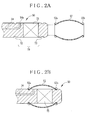
- the balloon 52 has a shape of a drum, or a shape of a rotating body with a greater diameter at an intermediate portion. Ring portions 52a and 52b project at ends of the balloon 52. Diameters of the ring portions 52a and 52b are slightly smaller than a diameter of the head assembly 50.
- a balloon support 70 is disposed at the head assembly 50 of the insertion tube 40 of the ultrasonic endoscope 10, and includes coupling grooves 72 and 73.
- the coupling grooves 72 and 73 extend circumferentially and are suitable for the ring portions 52a and 52b of the balloon 52.
- An interval between the coupling grooves 72 and 73 is substantially equal to that between the ring portions 52a and 52b.
- An end opening 54a is open between the coupling grooves 72 and 73 as an end opening of the flow channel 54.
- the balloon support 70 is connected with the flow opening 55 by the end opening 54a, where water is drawn into and out of the balloon 52.
- the ultrasonic transducer 75 is disposed between the coupling grooves 72 and 73 for emitting ultrasonic waves and receiving echo or reflected ultrasonic waves.
- the ultrasonic transducer 75 is covered by the balloon 52 attached to the balloon support 70. Thus, ultrasonic waves are applied through the inside of the balloon 52, and can be prevented from attenuation with air.
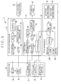
- the ultrasonic endoscope 10 includes a correlated double sampling/programmable gain amplifier (CDS/PGA) 81 and the CCD 80 in addition to the inflation and deflation buttons 56 and 57 and the ultrasonic transducer 75.
- the CCD 80 and the ultrasonic transducer 75 are disposed in the head assembly 50 at the end of the insertion tube 40.
- the CCD 80 picks up an object image of object light incident through the imaging window, to output an image signal according to the object image.
- the CDS/PGA 81 processes the image signal from the CCD 80 in the noise reduction and amplification.
- the ultrasonic transducer 75 is an array of plural ultrasonic transducer elements.
- the ultrasonic transducer 75 emits ultrasonic waves.
- the ultrasonic transducer 75 receives ultrasonic waves reflected by an object in a body cavity, converts those piezoelectrically, and produces a detection signal according to the reflected ultrasonic waves.
- the endoscope processor 14 includes a first timing generator 84, a CCD driver 85, an A/D converter 86, an endoscopic image generator 87 and a controller 88 for controlling various circuit elements in the endoscope processor 14.
- the first timing generator 84 is controlled by the controller 88 and inputs a timing signal or clock pulse to the CCD driver 85.
- the CCD driver 85 in response to this inputs a drive signal to the CCD 80, of which the timing of reading the stored charge and an electronic shutter speed are controlled.
- the A/D converter 86 converts an image signal of an analog form from the CDS/PGA 81 into digital image data.
- the endoscopic image generator 87 processes the digital image data in image processing of various functions, to create an endoscopic image. Also, the endoscopic image generator 87 converts the endoscopic image into a video signal (component signal, composite signal and the like) suitable for the format of the endoscope monitor display panel 20, and outputs the video signal. Thus, the endoscopic image is displayed on the endoscope monitor display panel 20.
- the ultrasonic processor 12 includes a second timing generator 90, a transmitter 91, a receiver 92, an A/D converter 93, an ultrasonic image generator 94, and a controller 95.
- the inflation and deflation buttons 56 and 57 are connected with the controller 95 by the universal cable 44.
- the controller 95 is connected with the pump apparatus 22 by the cable 36.
- the second timing generator 90 is controlled by the controller 95 and sends a drive pulse to the transmitter 91.
- the transmitter 91 in response to this supplies an excitation pulse or pulse voltage to the ultrasonic transducer 75 to emit ultrasonic waves.
- a detection signal is output by the ultrasonic transducer 75 upon the excitation pulse, and is received by the receiver 92, and is sent to the A/D converter 93.
- the A/D converter 93 converts the detection signal of an analog form from the receiver 92 into image data of a digital form.
- the ultrasonic image generator 94 processes the image data from the A/D converter 93 in image processing of various functions, and creates an ultrasonic image.
- the ultrasonic image generator 94 converts the ultrasonic image into a video signal (component signal, composite signal or the like) according to the format of the ultrasonic monitor display panel 18, and outputs the video signal.
- the ultrasonic monitor display panel 18 displays the ultrasonic image.
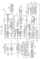
- the pump apparatus 22 includes the rotary pump 100, a driver 101 and a pump controller 102 as evaluator.
- the rotary pump 100 supplies water to and discharges water from the balloon 52.
- the driver 101 drives the rotary pump 100.
- the pump controller 102 controls various circuit elements of the pump apparatus 22.
- the flow setting wheels 62 and 63 are connected with the pump controller 102 for setting reference amounts of ultrasonic transmission medium.
- the pump controller 102 is connected with the controller 95 of the ultrasonic processor 12 by the cable 36.
- the controller 95 of the ultrasonic processor 12 responds to depression of the inflation button 56, and sends an inflation signal to the pump controller 102 for instructing the inflation of the balloon 52.
- the pump controller 102 in response to the inflation signal sends a supply signal to the driver 101 according to a setting of the first flow setting wheel 62.
- the driver 101 controls a rotational direction and rotational speed of a rotor according to the supply signal in the rotary pump 100, and draws water from the water tank 24 to inflate the balloon 52.
- the controller 95 sends a deflation signal to the pump controller 102 for deflation of the balloon 52.
- the pump controller 102 in response to this sends a discharge signal (control signal) to the driver 101 according to the reference amount set by the second flow setting wheel 63.
- the driver 101 drives the rotary pump 100 according to the discharge signal, and deflates the balloon 52 by discharging water.
- a flow meter 104 as measuring device is also included in the pump apparatus 22 and measures a supply amount and discharge amount of water to the balloon 52 by means of the rotary pump 100.
- the flow meter 104 inputs measured information of the supply amount and discharge amount to the pump controller 102.
- the pump controller 102 upon receiving the inflation signal for inflation, sends a supply signal to the driver 101, and checks whether the supply amount is higher than a reference amount predetermined in the system.
- the balloon 52 if inflated excessively, is likely to break in the body cavity or drop from the balloon support 70.
- the pump controller 102 if the supply amount is found higher than the reference amount, sends an inflation termination signal to the controller 95.
- the controller 95 upon receiving the inflation termination signal, causes the ultrasonic monitor display panel 18 to display a first alarm message 106 or dialog box as alarm device as illustrated in Fig. 4A , to indicate an alarm state for possibility of excessive inflation of the balloon 52.
- the pump controller 102 when the supply amount is found more than the reference amount, sends the inflation termination signal to the controller 95 until the stop of the inflation signal from the controller 95, or until the release of depression of the inflation button 56. Display of the first alarm message 106 is continued. Thus, it is possible to prevent excessive inflation of the balloon 52 by displaying the warning.
- the pump controller 102 in response to a deflation signal for deflation, sends a discharge signal to the driver 101, and checks whether the discharge amount from the flow meter 104 has become higher than a reference amount.
- the balloon 52 if deflated excessively, may be deformed by force of suction, or may be trapped or jammed in the end opening 54a of the flow channel 54. Also, it is likely that air or fluid enters the flow channel 54 through clearance between the ring portions 52a and 52b and the coupling grooves 72 and 73. A successive operation of inflating the balloon 52 may create bubbles by entry of the air or fluid in the balloon 52.
- the pump controller 102 upon detecting that the discharge amount becomes higher than the reference amount, sends a deflation termination signal to the controller 95 to stop the deflation.
- the controller 95 in response to this causes a second alarm message 108 or dialog box as alarm device to appear on the ultrasonic monitor display panel 18, so as to emit an alarm signal of possibility of excessive deflation of the balloon 52. See Fig. 4B .
- the pump controller 102 continues displaying the second alarm message 108 by transmission of the deflation termination signal to the controller 95 after detection of the discharge amount higher than the reference amount and until the stop of the deflation signal from the controller 95, namely until release of depression of the deflation button 57.
- the reference amounts for use in the evaluation may be predetermined suitably for the volume of the balloon 52 or other information.
- the operation of the ultrasonic diagnosis system 2 is described now.
- a physician or operator in a hospital sets up various elements of the ultrasonic diagnosis system 2 as illustrated in Fig. 1 .
- the balloon 52 is completely emptied of water, and is retained in a deflated state to contact the outer surface of the head assembly 50 tightly.
- the physician depresses a start button (not shown) of the endoscope processor 14.
- a signal for start of the diagnosis is sent to various circuit elements in the ultrasonic diagnosis system 2.
- the CCD 80 is caused by the CCD driver 85 to pick up an object image of object light incident through the imaging window, to output an image signal according to the object image.
- the image signal is processed by the CDS/PGA 81 for noise reduction and amplification, output to the A/D converter 86, and converted into image data of a digital form.
- the image data is input to the endoscopic image generator 87.
- the endoscopic image generator 87 processes the image data in the image processing of various functions, to create an endoscopic image.
- the endoscopic image generator 87 converts the endoscopic image into a video signal suitable for the format of the endoscope monitor display panel 20, and outputs the video signal. Thus, the endoscopic image is displayed on the endoscope monitor display panel 20.
- the controller 95 in the ultrasonic processor 12 starts the control of the second timing generator 90 upon receiving the start signal.
- the second timing generator 90 is controlled by the controller 95 to input a drive pulse to the transmitter 91.
- the transmitter 91 supplies an excitation pulse to the ultrasonic array transducer 75.
- the ultrasonic transducer 75 emits ultrasonic waves according to the excitation pulse from the transmitter 91, and receives ultrasonic waves reflected by the object.
- the reflected ultrasonic waves are converted piezoelectrically to create a detection signal.
- the detection signal is transmitted to the receiver 92 in the ultrasonic processor 12.
- the receiver 92 outputs the detection signal to the A/D converter 93.
- the detection signal is converted into image data of a digital form by the A/D converter 93, and input to the ultrasonic image generator 94.
- the ultrasonic image generator 94 creates an ultrasonic image by image processing of the digital image data.
- the ultrasonic image is converted into a video signal compatible to the ultrasonic monitor display panel 18, and outputs the video signal.
- the ultrasonic monitor display panel 18 displays the ultrasonic image.
- each of the display panels 18 and 20 When each of the display panels 18 and 20 is started for display, a physician enters the insertion tube 40 of the ultrasonic endoscope 10 in a body cavity of a patient's body for imaging of an object. At first, an endoscopic image is viewed. If a lesion is discovered in the object in the endoscopic image, or if he or she wishes to view the tissue of the object more precisely, then observation is changed over to an ultrasonic image.
- the inflation button 56 is depressed to inflate the balloon 52 by supplying water from the water tank 24.
- a supply amount or flow volume of the supply to the balloon 52 is adjustable by operation of the first flow setting wheel 62.
- the pump controller 102 checks whether the supply amount to the balloon 52 has become higher than a reference amount.
- the pump controller 102 if the supply amount is found higher than the reference amount, transmits an inflation termination signal to the controller 95.
- the controller 95 in response to this causes the ultrasonic monitor display panel 18 to display the first alarm message 106 to inform possibility of excessive inflation of the balloon 52. Thus, excessive inflation of the balloon 52 can be prevented.
- the physician causes the balloon 52 after the inflation to contact an object or lesion tightly. Then an ultrasonic image of the object is displayed on the ultrasonic monitor display panel 18. A state of submucosal tissue of the object can be viewed in detail.
- the physician moves and separates the balloon 52 from the object upon he or she finishes viewing the ultrasonic image.
- the deflation button 57 is depressed to deflate the balloon 52 by discharging water. It is possible by operating the second flow setting wheel 63 to determine a flow volume of the water of discharge from the balloon 52. As the flow volumes in the course of the supply and discharge are discretely determined, adjusted operation is possible. For example, the balloon 52 can be inflated slowly with a small flow volume (flow rate) in the supply, and can be deflated quickly with a great flow volume (flow rate) in the discharge.
- the pump controller 102 checks whether the discharge amount of the balloon 52 has become higher than a reference amount. If the discharge amount is found higher than the reference amount, then the pump controller 102 outputs a deflation termination signal to the controller 95 to stop the deflation.
- the controller 95 upon receiving the deflation termination signal, causes the ultrasonic monitor display panel 18 to display the second alarm message 108 as alarm signal of possibility of excessive deflation of the balloon 52. This is effective in preventing the excessive deflation of the balloon 52.
- operability of the ultrasonic diagnosis system 2 can be high because the balloon 52 can be inflated and deflated by manual operation of the inflation and deflation buttons 56 and 57 on the handle 42 of the ultrasonic endoscope 10. Also, an operator can carefully observe the display panels 18 and 20, and can be free from errors in operation of other medical instruments. Safety in the course of the diagnosis can be high. Furthermore, high reliability of the ultrasonic diagnosis system 2 can be obtained, because the flow channel 54 as single conduit can operate for flow in forward and backward directions without need of complicated structure for supply and discharge of water with the balloon 52.
- the ultrasonic processor 12 is a control unit for inputting inflation and deflation signals to the pump apparatus 22.
- the endoscope processor 14 can be a control unit for inputting inflation and deflation signals to the pump apparatus 22.
- the inflation and deflation buttons 56 and 57 may be connected with the pump controller 102 of the pump apparatus 22 to input the signals to the pump apparatus 22 directly from the ultrasonic endoscope 10.
- the inflation and deflation buttons 56 and 57 are used.
- structures for control of inflation and deflation may have any suitable form other than the inflation and deflation buttons 56 and 57.
- the flow meter 104 measures the flow volumes of the supply and discharge of water with the balloon 52. Furthermore, a pressure meter is preferably associated with the pump apparatus 22 to measure the flow volumes of the supply and discharge of water according to pressure applied in the conduit of the water.
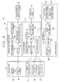
- a pump apparatus 112 has a timer 111 as measuring device for measuring at least one of the supply time or discharge time in operation of the rotary pump 100.
- the timer 111 is connected with the pump controller 102.
- the timer 111 measures a length of a period of a supply signal or discharge signal from the pump controller 102 to the driver 101.
- the pump controller 102 stores a data table (not shown) of a relationship between the length of the period of the supply signal or discharge signal and the supply amount or discharge amount, the relationship being determined for respective values of adjustment of the flow setting wheels 62 and 63.
- the pump controller 102 determines the supply amount or discharge amount according to the data table and time measured by the timer 111, and carries out the evaluation described above.
- a pump apparatus 117 includes a rotary encoder 116 as detector or measuring device for detecting at least one of the number of rotations of the rotor and its rotational angle.
- the pump controller 102 determines the supply amount or discharge amount according to the data table and a detection result from the rotary encoder 116, the data table being constituted by the relationship between the rotation number or rotational angle of the rotor and the supply amount or discharge amount, the relationship being determined for respective settings of the flow setting wheels 62 and 63. It is also possible to carry out the evaluation according to the rotation number or rotational angle itself of the rotor detected by the rotary encoder 116.
- Figs. 5 and 6 have advantages in reducing the cost in comparison with the use of the flow meter or pressure meter. It is possible to measure the supply amount or discharge amount with a simple structure without complicated structure to detect a flow volume or pressure. Should a flow meter or pressure meter be used, there is a problem of additional operation of cleaning and disinfection as water directly contacts the meter. However, it is possible according to the embodiments to measure the supply amount or discharge amount without contacting the water. There is no problem of additional cleaning and disinfection.
- the pump controller 102 obtains an accumulated value of the supply amount or discharge amount. If a first button among those and identical with that depressed previously is depressed, then the supply amount or discharge amount of this time is added to an accumulated value of the supply amount or discharge amount. If a second button different from the first depressed previously is depressed, then the supply amount or discharge amount of this time is subtracted from an accumulated value of the supply amount or discharge amount. Thus, it is possible exactly to recognize the total of the water supplied into the balloon 52.
- the first and second alarm messages 106 and 108 operate for the alarm information.
- Information displayed on the ultrasonic monitor display panel 18 is the alarm information.
- an alarm device may be an alarm sound source, alarm light source and the like for alarm information related to an increase in the supply amount and discharge amount over the reference amount.
- the alarm device operates upon an increase of the supply amount and discharge amount over the reference amount.
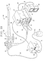
- an ultrasonic endoscope 122 in an ultrasonic diagnosis system 120 has a first button 124, a second button 125, a third button 126 and a fourth button 127 disposed on the handle 42 as pushbuttons or switches.
- signal lines from the first to fourth buttons 124-127 extend to a controller 132 in an ultrasonic processor 130 by use of the universal cable 44 or the like.
- a keyboard 134 is associated with the controller 132 for inputting alphanumeric information, command signals and other various signals.
- a button function memory 136 is incorporated in the controller 132 and stores functions of the first to fourth buttons 124-127.
- data in the button function memory 136 are relationships between information of the first to fourth buttons 124-127 and the functions assigned to those.
- the controller 132 refers to the button function memory 136 to check the functions, so as to perform tasks according to the functions.
- the first button 124 is assigned with a function of inflation of the balloon.
- the first button 124 operates by way of the inflation button 56 of the first embodiment.
- the controller 132 sends an inflation signal to inflate the balloon 52.
- the second button 125 is assigned with a function of deflation of the balloon.
- the second button 125 operates by way of the deflation button 57 of the first embodiment.
- the controller 132 generates a deflation signal to deflate the balloon 52.
- the third button 126 is assigned with a freezing function, to operate as a freezing button.
- the controller 132 causes the display panels 18 and 20 to display ultrasonic and endoscopic images in a form of still images.
- the fourth button 127 is assigned with a release function, to operate as a release button. When the fourth button 127 is depressed, the controller 132 operates for recording of ultrasonic and endoscopic images in a form of still images.
- Functions of the first to fourth buttons 124-127 can be set up as desired by manual operation of the keyboard 134 to rewrite the button function memory 136.
- the first button 124 comes to operate as a freezing button in place of operation of the inflation button 56.
- the second button 125 comes to operate as a release button in place of operation of the deflation button 57.
- the third button 126 comes to operate as the inflation button 56 in place of operation of the freezing button.
- the fourth button 127 comes to operate as the deflation button 57 in place of operation of the release button.
- the first to fourth buttons 124-127 can be set for desired functions.
- the working efficiency of the ultrasonic endoscope 122 can be high because the inflation and deflation buttons 56 and 57 can be positioned by use of the first to fourth buttons 124-127 according to a specific diagnosis or preferences in the department of physicians.
- the button function memory 136 is incorporated in the controller 132.
- the button function memory 136 may be incorporated in the ultrasonic endoscope 122, where the functions of the first to fourth buttons 124-127 may be discerned in the ultrasonic endoscope 122.
- the positions, number and functions of plural buttons in the handle 42 are not limited to the above embodiment.
- switches in the handle 42 are not limited to the first to fourth buttons 124-127 as depressible switches, but can be slide switches, toggle switches and other switches.
- a remote control unit 142 has an inflation button 143 and a deflation button 144 as input devices.
- a retention mechanism 152 is disposed on an ultrasonic endoscope 150, and retains the remote control unit 142 on the handle 42 in a removable manner. See Fig. 11 .
- Examples of the retention mechanism 152 include a sliding type such as an accessory shoe of a camera, a rotatable type such as a bayonet mechanism, a screw type, a magnet type or the like well-known in the art.
- a transmitter 145 is incorporated in the remote control unit 142.
- An antenna 146 for transmission is connected with the transmitter 145 as well as the inflation and deflation buttons 143 and 144.
- the inflation button 143 When the inflation button 143 is depressed, the transmitter 145 generates the inflation signal, and converts this into a signal for wireless communication.
- a radio wave of the signal is emitted by the antenna 146.
- the deflation button 144 When the deflation button 144 is depressed, the transmitter 145 generates the deflation signal, and converts this into a signal for wireless communication.
- a radio wave of the signal is emitted by the antenna 146.
- a pump apparatus 154 includes an antenna 155 and a receiver 156.
- the antenna 155 receives a radio wave from the remote control unit 142, and converts this into a signal which is input to the receiver 156.
- the receiver 156 demodulates the signal to obtain the inflation or deflation signal in an initial form, which is input to the pump controller 102.
- the pump controller 102 controls the rotary pump 100 according to the inflation or deflation signal, to supply or discharge water in relation to the balloon 52.
- the inflation and deflation buttons 143 and 144 on the remote control unit 142 are effective in raising the working efficiency of the ultrasonic endoscope 150, because the remote control unit 142 is removable on the handle 42 and sends signals to the pump apparatus 154 wirelessly.
- the remote control unit 142 although removable in the embodiment, may be disposed on the handle 42 in a stationary manner.
- the receiver 156 in the ultrasonic processor 12 or the endoscope processor 14, receive signals, and transmit the signals to the pump apparatus 154.
- the ultrasonic transducer 75 is oriented in a lateral direction in the head assembly of the ultrasonic endoscope 10.
- the ultrasonic transducer 75 of the ultrasonic endoscope 10 can be oriented straight from the distal end of the head assembly, namely in a longitudinal direction.
- the balloon 52 has the two open ends having the ring portions 52a and 52b.
- the balloon 52 in the invention can have a bag shape, and has one closed end positioned opposite to a single open end.
- the device in connection with the pump apparatus of the invention is the ultrasonic endoscope.
- a device in connection with a pump apparatus of the invention may be an ultrasonic probe for use by insertion through a forceps channel of an electronic endoscope.
- ultrasonic transmission medium for use in the balloon 52, in place of the water of the embodiments may be other liquid or gas for the purpose of preventing attenuation of ultrasonic waves.
- a pump in the pump apparatus, in place of the rotary pump 100 may be any type of pump for the purpose of supply and discharge of transmission medium of transmission.
Landscapes
- Health & Medical Sciences (AREA)
- Life Sciences & Earth Sciences (AREA)
- Surgery (AREA)
- Nuclear Medicine, Radiotherapy & Molecular Imaging (AREA)
- Medical Informatics (AREA)
- Pathology (AREA)
- Radiology & Medical Imaging (AREA)
- Engineering & Computer Science (AREA)
- Biomedical Technology (AREA)
- Heart & Thoracic Surgery (AREA)
- Physics & Mathematics (AREA)
- Molecular Biology (AREA)
- Biophysics (AREA)
- Animal Behavior & Ethology (AREA)
- General Health & Medical Sciences (AREA)
- Public Health (AREA)
- Veterinary Medicine (AREA)
- Optics & Photonics (AREA)
- Ultra Sonic Daignosis Equipment (AREA)
Abstract
Description
- The present invention relates to an ultrasonic diagnosis system and pump apparatus. More particularly, the present invention relates to an ultrasonic diagnosis system and pump apparatus in which a balloon at an end of an ultrasonic endoscope can operate reliably for inflation and deflation.
- Ultrasonic diagnosis in the medical field is a non-invasive diagnosis for applying ultrasonic waves to an object in a patient's body, to observe a state of the object by receiving and imaging echo ultrasonically reflected from the object. An example of ultrasonic diagnosis is in-vivo diagnosis for applying the ultrasonic waves upon entry of a probe in a body cavity. It is possible in the in-vivo diagnosis to examine the tissue of the body cavity or gastrointestinal tract more precisely than in extracorporeal device diagnosis with the ultrasonic waves. The in-vivo diagnosis is important specifically for diagnosing the depth of ulcer, tumor and the like in the body.
- Examples of instruments for the in-vivo diagnosis include an ultrasonic endoscope having an ultrasonic transducer array and CCD at its distal end, and an ultrasonic probe for use by insertion through a forceps channel of an endoscope. If there is a clearance between the ultrasonic endoscope or the ultrasonic probe and the surface in the body cavity, air exists to attenuate the ultrasonic waves remarkably. In view of such a problem,
U.S.P. No. 6, 142, 945 (corresponding toJP-A 11-155865 -
U.S.P. No. 6,142,945 (corresponding toJP-A 11-155865 - Also, it is conceivable to use an electric pump for supplying and discharging the transmission medium in relation to the balloon for the purpose of the inflation and deflation of the balloon. The second hand of the physician can be made free, because of no need of manually holding the syringe pump. However, the physician must operate a switch on a pump body which is installed separately, so that operability of the construction for operating the conduits is not higher.
- If the physician carries out the inflation and deflation of the balloon, it is likely to damage the tissue surface of the body cavity with an error in operation of the switch, because he or she must gaze the switch in place of viewing a display panel displaying an ultrasonic or endoscopic image. It is conceivable to connect a foot switch with the pump for the purpose of driving and stopping the same. However, an error in operation of the foot switch is likely to occur specifically because a plurality of the foot switches are used additionally in connection with other medical instruments.
- It is conceivable to carry out the inflation and deflation of the balloon by use of conduits for supply of air and water to the body cavity in the in-vivo diagnosis with the ultrasonic endoscope. However, the conduits for supply of air and water have a complicated structure in which valves change over the conduits between open and closed states. Applied use of the conduits of supply of air and water for the inflation and deflation of the balloon causes a problem of higher complexity in the structure, because the numbers of the valves and the conduits increase. The structural complexity will lower the reliability, because jamming is more likely to occur in the conduits.
- In view of the foregoing problems, an object of the present invention is to provide an ultrasonic diagnosis system and pump apparatus in which a balloon at an end of an ultrasonic endoscope can operate reliably for inflation and deflation.
- In order to achieve the above and other objects and advantages of this invention, an ultrasonic diagnosis system having an ultrasonic endoscope and a pump apparatus is provided. The ultrasonic endoscope includes an ultrasonic transducer for emitting ultrasonic waves and receiving reflected ultrasonic waves. A balloon support supports a resilient balloon mounted thereon hermetically and removably to cover the ultrasonic transducer. A first flow opening passes an ultrasonic transmission medium. One flow channel is formed between the first flow opening and the balloon support, for flow of the transmission medium into and out of the balloon in forward and backward directions. An inflation input device inputs a signal to the pump apparatus for inflating the balloon. A deflation input device inputs a signal to the pump apparatus for deflating the balloon. The pump apparatus includes a second flow opening connected with the first flow opening by a tube. A pump supplies the transmission medium through the tube and the flow channel to inflate the balloon, and discharges the transmission medium from the balloon to deflate the balloon. There is a pump controller for control of the pump in response to the inflation signal to supply the transmission medium, and for control of the pump in response to the deflation signal to discharge the transmission medium.
- Furthermore, a processor is connected with the ultrasonic endoscope and the pump apparatus, for inputting the inflation and deflation signals to the pump apparatus.
- The ultrasonic endoscope includes plural switches adapted to selected functions, and including a first switch for constituting the inflation input device and a second switch for constituting the deflation input device.
- The ultrasonic endoscope includes a transmitter, having the inflation and deflation input devices, for wirelessly transmitting the inflation and deflation signals.
- Furthermore, a retention mechanism retains the transmitter on the ultrasonic endoscope removably.
- The pump apparatus further includes a first flow setting device for setting a supply amount of supply of the transmission medium. A second flow setting device sets a discharge amount of discharge of the transmission medium. The controller controls the pump to supply the transmission medium at the supply amount and to discharge the transmission medium at the discharge amount.
- The pump apparatus further includes a measuring device for measuring at least one of a supply amount of the transmission medium to the balloon and a discharge amount of the transmission medium from the balloon.
- Furthermore, an evaluator evaluates the supply amount or the discharge amount by comparison with a reference amount. An alarm unit generates an alarm signal if the supply amount or the discharge amount has become higher than the reference amount.
- In one preferred embodiment, the measuring device includes a timer for measuring at least one of a supply time and discharge time of the transmission medium with the pump.
- In another preferred embodiment, the pump is a rotary pump for supplying and discharging the transmission medium by rotations. The measuring device detects at least one of a number and angle of the rotations of the rotary pump.
- In still another preferred embodiment, the measuring device is a flow meter.
- The balloon support includes first and second ring portions positioned at respectively first and second ends of the balloon. A first coupling portion is disposed in an endoscope distal end portion and close to the ultrasonic transducer, and having the first ring portion fitted thereon. A second coupling portion is disposed between the ultrasonic transducer and an endoscope proximal side, and having the second ring portion fitted thereon.
- In one aspect of the invention, a pump apparatus for use in connection with an ultrasonic endoscope is provided. The ultrasonic endoscope includes an ultrasonic transducer for emitting and receiving ultrasonic waves, a balloon support, having the ultrasonic transducer, for supporting a balloon mounted thereon to cover the ultrasonic transducer hermetically and removably, an inflation input device adapted to inflating the balloon, and a deflation input device adapted to deflating the balloon. In the pump apparatus, a pump draws transmission medium through a flow line disposed to extend to the balloon, to cause the transmission medium to flow into and out of the balloon. A pump controller controls the pump, inflates the balloon by supplying the transmission medium in response to an inflation signal from the inflation input device, and deflates the balloon by discharging the transmission medium in response to a deflation signal from the deflation input device.
- In another aspect of the invention, an ultrasonic diagnosis system is provided, and includes an ultrasonic endoscope having an ultrasonic transducer for emitting and receiving ultrasonic waves, a balloon support, having the ultrasonic transducer, for supporting a balloon mounted thereon to cover the ultrasonic transducer hermetically and removably. In the ultrasonic diagnosis system, the ultrasonic endoscope includes an inflation input device adapted to inflating the balloon. A deflation input device is adapted to deflating the balloon. Furthermore, a flow line extends to the balloon to pass transmission medium. A pump apparatus includes a pump for drawing the transmission medium through the flow line, to cause the transmission medium to flow into and out of the balloon. A pump controller controls the pump, inflates the balloon by supplying the transmission medium in response to an inflation signal from the inflation input device, and deflates the balloon by discharging the transmission medium in response to a deflation signal from the deflation input device.
- Accordingly, the balloon at an end of an ultrasonic endoscope can operate reliably for inflation and deflation, because the inflation and deflation input devices are effective in easily instructing the flow of the transmission medium into or out of the balloon.
- The above objects and advantages of the present invention will become more apparent from the following detailed description when read in connection with the accompanying drawings, in which:
-
Fig. 1 is a perspective view illustrating an ultrasonic diagnosis system; -
Fig. 2A is a vertical section illustrating a distal end of an ultrasonic endoscope where a balloon is separated; -
Fig. 2B is a vertical section illustrating the same asFig. 2A but where the balloon is secured; -
Fig. 3 is a block diagram schematically illustrating the ultrasonic diagnosis system; -
Fig. 4A is a front elevation illustrating appearance of a display panel with a first alarm message; -
Fig. 4B is a front elevation illustrating appearance of a display panel with a second alarm message; -
Fig. 5 is a block diagram schematically illustrating one preferred ultrasonic diagnosis system in which supply and discharge amounts are measured; -
Fig. 6 is a block diagram schematically illustrating another preferred ultrasonic diagnosis system having a rotary encoder; -
Fig. 7 is a perspective view illustrating one preferred embodiment having plural buttons; -
Fig. 8 is a block diagram schematically illustrating an ultrasonic diagnosis system having the plural buttons; -
Fig. 9A is a table illustrating a set of button functions stored in a button function memory; -
Fig. 9B is a table illustrating another preferred set of button functions; -
Fig. 10 is a perspective view illustrating one preferred embodiment having a remote control unit; -
Fig. 11 is a block diagram schematically illustrating an ultrasonic diagnosis system having the remote control unit. - In
Fig. 1 , anultrasonic diagnosis system 2 includes anultrasonic endoscope 10, anultrasonic processor 12, anendoscope processor 14, alight source unit 16, an ultrasonicmonitor display panel 18, an endoscopemonitor display panel 20, apump apparatus 22, and awater tank 24 as water source. Theultrasonic endoscope 10 picks up an image of an object in a body cavity or gastrointestinal tract. Theultrasonic processor 12 creates an ultrasonic image. Theendoscope processor 14 creates an endoscopic image. Thelight source unit 16 generates illumination light for illuminating the object. The ultrasonicmonitor display panel 18 displays the ultrasonic image. The endoscopemonitor display panel 20 displays the endoscopic image. Thepump apparatus 22 causes water to flow into and out of theultrasonic endoscope 10. Thewater tank 24 stores the water in connection with thepump apparatus 22. - The
ultrasonic endoscope 10 includes aninsertion tube 40, ahandle 42 and auniversal cable 44. Thehandle 42 is a base portion from which theinsertion tube 40 extends. A first end of theuniversal cable 44 is connected with thehandle 42. A second end of theuniversal cable 44 has acontact plug 46 or connector, anendoscope plug 47 or connector, and a light source plug 48 or connector. Thecontact plug 46 is connected with theultrasonic processor 12. The endoscope plug 47 is connected with theendoscope processor 14. The light source plug 48 is connected with thelight source unit 16. Thus, theultrasonic endoscope 10 is connected with theultrasonic processor 12, theendoscope processor 14 and thelight source unit 16 by the plugs 46-48. - The
insertion tube 40 is in a tubular form, and has flexibility. Ahead assembly 50 at a distal end of theinsertion tube 40 has anultrasonic array transducer 75 ofFig. 2 and aCCD 80 ofFig. 3 . Aballoon 52 with resiliency is attached to thehead assembly 50. Theballoon 52 is entered in the body cavity in a deflated state in tight contact with the outer surface of thehead assembly 50. For the time of emitting ultrasonic waves from theultrasonic transducer 75, theballoon 52 is inflated by water supplied by thepump apparatus 22. The contact of thehead assembly 50 with the object in the body cavity is tightened at theballoon 52. Ultrasonic waves from theultrasonic transducer 75 and reflected ultrasonic waves are prevented from attenuation with air or other fluid. After the inflation, theballoon 52 is deflated again by draining water. An example of the material for theballoon 52 is latex rubber. Note that the water for theballoon 52 is preferably degassed water obtained by degassing of dissolved gas. - A
flow channel 54 is formed through theinsertion tube 40 and thehandle 42 for flow of water to and from theballoon 52. A first open end of theflow channel 54 appears in thehead assembly 50. A flow opening 55 is disposed at the proximal end of thehandle 42. A second open end of theflow channel 54 is open through theflow opening 55. Thehandle 42 includes aninflation button 56 and adeflation button 57 as input devices. Theinflation button 56 is operable to cause thepump apparatus 22 to dispense water to inflate theballoon 52. Thedeflation button 57 is operable to cause thepump apparatus 22 to discharge water to deflate theballoon 52. - A first flow opening 60 and a second flow opening 61 are formed in the
pump apparatus 22.Tubes second flow openings tube 30 is connected with the first flow opening 60. A second tube end of thetube 30 is connected with theflow opening 55. A first end of thetube 31 is connected with the second flow opening 61. A second end of thetube 31 is connected with atube connector 24a of thewater tank 24. Thus, a flow line from thewater tank 24, via thetube 31, thepump apparatus 22, thetube 30 and theflow channel 54 to theballoon 52 is defined. - A
rotary pump 100 ofFig. 3 is included in thepump apparatus 22, makes a rotor to rotate for creating a flow of ultrasonic transmission medium or water in the flow line, and changes over a direction of the flow selectively by changing the rotational direction of the rotor. Thepump apparatus 22 drives therotary pump 100 to draw transmission medium from one of the first andsecond flow openings JP-A 2001-321329 rotary pump 100. - When the
inflation button 56 is depressed, therotary pump 100 in thepump apparatus 22 is controlled for suction through the second flow opening 61 and delivery through the first flow opening 60, to draw water from thewater tank 24 into theballoon 52. When thedeflation button 57 is depressed, therotary pump 100 is controlled for suction through the first flow opening 60 and delivery through the second flow opening 61, to draw water from theballoon 52 back to thewater tank 24. - The
pump apparatus 22 includes a firstflow setting wheel 62 and a secondflow setting wheel 63 as flow setting device. The firstflow setting wheel 62 adjusts a flow volume in the supply of water per unit time, namely a flow rate. The secondflow setting wheel 63 adjusts a flow volume in the discharge of water per unit time, namely a flow rate. Thepump apparatus 22 discretely controls the flow volumes of the supply and discharge according to the settings of theflow setting wheels balloon 52 from inflating abruptly or breaking, and keep theballoon 52 tightly secured to thehead assembly 50 without drop. Theballoon 52 can be deflated rapidly to raise the efficiency in the diagnosis. - A
cable 34 connects theultrasonic processor 12 to the ultrasonicmonitor display panel 18. Theultrasonic processor 12 outputs an ultrasonic image through thecable 34 for the ultrasonicmonitor display panel 18 to display the same. Acable 35 connects theendoscope processor 14 to the endoscopemonitor display panel 20. Theendoscope processor 14 outputs the endoscopic image through thecable 35 for the endoscopemonitor display panel 20 to display the same. Acable 36 connects theultrasonic processor 12 to thepump apparatus 22. Various signals are transmitted and received between theultrasonic processor 12 and thepump apparatus 22 through thecable 36. - In
Fig. 2A , theballoon 52 has a shape of a drum, or a shape of a rotating body with a greater diameter at an intermediate portion.Ring portions balloon 52. Diameters of thering portions head assembly 50. - A
balloon support 70 is disposed at thehead assembly 50 of theinsertion tube 40 of theultrasonic endoscope 10, and includescoupling grooves coupling grooves ring portions balloon 52. An interval between thecoupling grooves ring portions balloon 52 to theballoon support 70, at first thering portions head assembly 50 is inserted in theballoon 52. Thering portions coupling grooves balloon 52. InFig. 2B , theballoon 52 is secured to theballoon support 70 removably and hermetically. - An
end opening 54a is open between thecoupling grooves flow channel 54. Theballoon support 70 is connected with the flow opening 55 by theend opening 54a, where water is drawn into and out of theballoon 52. Theultrasonic transducer 75 is disposed between thecoupling grooves ultrasonic transducer 75 is covered by theballoon 52 attached to theballoon support 70. Thus, ultrasonic waves are applied through the inside of theballoon 52, and can be prevented from attenuation with air. - In
Fig. 3 , circuit arrangement of theultrasonic diagnosis system 2 is schematically illustrated. Theultrasonic endoscope 10 includes a correlated double sampling/programmable gain amplifier (CDS/PGA) 81 and theCCD 80 in addition to the inflation anddeflation buttons ultrasonic transducer 75. TheCCD 80 and theultrasonic transducer 75 are disposed in thehead assembly 50 at the end of theinsertion tube 40. TheCCD 80 picks up an object image of object light incident through the imaging window, to output an image signal according to the object image. The CDS/PGA 81 processes the image signal from theCCD 80 in the noise reduction and amplification. - The
ultrasonic transducer 75 is an array of plural ultrasonic transducer elements. Theultrasonic transducer 75 emits ultrasonic waves. Theultrasonic transducer 75 receives ultrasonic waves reflected by an object in a body cavity, converts those piezoelectrically, and produces a detection signal according to the reflected ultrasonic waves. - The
endoscope processor 14 includes afirst timing generator 84, aCCD driver 85, an A/D converter 86, anendoscopic image generator 87 and acontroller 88 for controlling various circuit elements in theendoscope processor 14. - The
first timing generator 84 is controlled by thecontroller 88 and inputs a timing signal or clock pulse to theCCD driver 85. TheCCD driver 85 in response to this inputs a drive signal to theCCD 80, of which the timing of reading the stored charge and an electronic shutter speed are controlled. - The A/
D converter 86 converts an image signal of an analog form from the CDS/PGA 81 into digital image data. Theendoscopic image generator 87 processes the digital image data in image processing of various functions, to create an endoscopic image. Also, theendoscopic image generator 87 converts the endoscopic image into a video signal (component signal, composite signal and the like) suitable for the format of the endoscopemonitor display panel 20, and outputs the video signal. Thus, the endoscopic image is displayed on the endoscopemonitor display panel 20. - The
ultrasonic processor 12 includes asecond timing generator 90, atransmitter 91, areceiver 92, an A/D converter 93, anultrasonic image generator 94, and acontroller 95. The inflation anddeflation buttons controller 95 by theuniversal cable 44. Thecontroller 95 is connected with thepump apparatus 22 by thecable 36. - The
second timing generator 90 is controlled by thecontroller 95 and sends a drive pulse to thetransmitter 91. Thetransmitter 91 in response to this supplies an excitation pulse or pulse voltage to theultrasonic transducer 75 to emit ultrasonic waves. A detection signal is output by theultrasonic transducer 75 upon the excitation pulse, and is received by thereceiver 92, and is sent to the A/D converter 93. - The A/
D converter 93 converts the detection signal of an analog form from thereceiver 92 into image data of a digital form. Theultrasonic image generator 94 processes the image data from the A/D converter 93 in image processing of various functions, and creates an ultrasonic image. Theultrasonic image generator 94 converts the ultrasonic image into a video signal (component signal, composite signal or the like) according to the format of the ultrasonicmonitor display panel 18, and outputs the video signal. Thus, the ultrasonicmonitor display panel 18 displays the ultrasonic image. - The
pump apparatus 22 includes therotary pump 100, adriver 101 and apump controller 102 as evaluator. Therotary pump 100 supplies water to and discharges water from theballoon 52. Thedriver 101 drives therotary pump 100. Thepump controller 102 controls various circuit elements of thepump apparatus 22. Theflow setting wheels pump controller 102 for setting reference amounts of ultrasonic transmission medium. Thepump controller 102 is connected with thecontroller 95 of theultrasonic processor 12 by thecable 36. - The
controller 95 of theultrasonic processor 12 responds to depression of theinflation button 56, and sends an inflation signal to thepump controller 102 for instructing the inflation of theballoon 52. Thepump controller 102 in response to the inflation signal sends a supply signal to thedriver 101 according to a setting of the firstflow setting wheel 62. Thedriver 101 controls a rotational direction and rotational speed of a rotor according to the supply signal in therotary pump 100, and draws water from thewater tank 24 to inflate theballoon 52. - When the
deflation button 57 is depressed, thecontroller 95 sends a deflation signal to thepump controller 102 for deflation of theballoon 52. Thepump controller 102 in response to this sends a discharge signal (control signal) to thedriver 101 according to the reference amount set by the secondflow setting wheel 63. Thedriver 101 drives therotary pump 100 according to the discharge signal, and deflates theballoon 52 by discharging water. - A
flow meter 104 as measuring device is also included in thepump apparatus 22 and measures a supply amount and discharge amount of water to theballoon 52 by means of therotary pump 100. Theflow meter 104 inputs measured information of the supply amount and discharge amount to thepump controller 102. - The
pump controller 102, upon receiving the inflation signal for inflation, sends a supply signal to thedriver 101, and checks whether the supply amount is higher than a reference amount predetermined in the system. Theballoon 52, if inflated excessively, is likely to break in the body cavity or drop from theballoon support 70. Thus, thepump controller 102, if the supply amount is found higher than the reference amount, sends an inflation termination signal to thecontroller 95. Thecontroller 95, upon receiving the inflation termination signal, causes the ultrasonicmonitor display panel 18 to display afirst alarm message 106 or dialog box as alarm device as illustrated inFig. 4A , to indicate an alarm state for possibility of excessive inflation of theballoon 52. - The
pump controller 102, when the supply amount is found more than the reference amount, sends the inflation termination signal to thecontroller 95 until the stop of the inflation signal from thecontroller 95, or until the release of depression of theinflation button 56. Display of thefirst alarm message 106 is continued. Thus, it is possible to prevent excessive inflation of theballoon 52 by displaying the warning. - The
pump controller 102, in response to a deflation signal for deflation, sends a discharge signal to thedriver 101, and checks whether the discharge amount from theflow meter 104 has become higher than a reference amount. Theballoon 52, if deflated excessively, may be deformed by force of suction, or may be trapped or jammed in the end opening 54a of theflow channel 54. Also, it is likely that air or fluid enters theflow channel 54 through clearance between thering portions coupling grooves balloon 52 may create bubbles by entry of the air or fluid in theballoon 52. - The
pump controller 102, upon detecting that the discharge amount becomes higher than the reference amount, sends a deflation termination signal to thecontroller 95 to stop the deflation. Thecontroller 95 in response to this causes asecond alarm message 108 or dialog box as alarm device to appear on the ultrasonicmonitor display panel 18, so as to emit an alarm signal of possibility of excessive deflation of theballoon 52. SeeFig. 4B . - The
pump controller 102 continues displaying thesecond alarm message 108 by transmission of the deflation termination signal to thecontroller 95 after detection of the discharge amount higher than the reference amount and until the stop of the deflation signal from thecontroller 95, namely until release of depression of thedeflation button 57. Thus, excessive deflation of theballoon 52 can be prevented by continuing indication of thesecond alarm message 108. Note that the reference amounts for use in the evaluation may be predetermined suitably for the volume of theballoon 52 or other information. - The operation of the
ultrasonic diagnosis system 2 is described now. At first, a physician or operator in a hospital sets up various elements of theultrasonic diagnosis system 2 as illustrated inFig. 1 . Theballoon 52 is completely emptied of water, and is retained in a deflated state to contact the outer surface of thehead assembly 50 tightly. The physician depresses a start button (not shown) of theendoscope processor 14. A signal for start of the diagnosis is sent to various circuit elements in theultrasonic diagnosis system 2. - The
controller 88 of theendoscope processor 14, in response to the command signal for the start, controls thefirst timing generator 84 to start driving theCCD 80 with theCCD driver 85. TheCCD 80 is caused by theCCD driver 85 to pick up an object image of object light incident through the imaging window, to output an image signal according to the object image. The image signal is processed by the CDS/PGA 81 for noise reduction and amplification, output to the A/D converter 86, and converted into image data of a digital form. The image data is input to theendoscopic image generator 87. Theendoscopic image generator 87 processes the image data in the image processing of various functions, to create an endoscopic image. Theendoscopic image generator 87 converts the endoscopic image into a video signal suitable for the format of the endoscopemonitor display panel 20, and outputs the video signal. Thus, the endoscopic image is displayed on the endoscopemonitor display panel 20. - The
controller 95 in theultrasonic processor 12 starts the control of thesecond timing generator 90 upon receiving the start signal. Thesecond timing generator 90 is controlled by thecontroller 95 to input a drive pulse to thetransmitter 91. In response to the drive pulse, thetransmitter 91 supplies an excitation pulse to theultrasonic array transducer 75. - The
ultrasonic transducer 75 emits ultrasonic waves according to the excitation pulse from thetransmitter 91, and receives ultrasonic waves reflected by the object. The reflected ultrasonic waves are converted piezoelectrically to create a detection signal. The detection signal is transmitted to thereceiver 92 in theultrasonic processor 12. Thereceiver 92 outputs the detection signal to the A/D converter 93. - The detection signal is converted into image data of a digital form by the A/
D converter 93, and input to theultrasonic image generator 94. Theultrasonic image generator 94 creates an ultrasonic image by image processing of the digital image data. The ultrasonic image is converted into a video signal compatible to the ultrasonicmonitor display panel 18, and outputs the video signal. Thus, the ultrasonicmonitor display panel 18 displays the ultrasonic image. - When each of the
display panels insertion tube 40 of theultrasonic endoscope 10 in a body cavity of a patient's body for imaging of an object. At first, an endoscopic image is viewed. If a lesion is discovered in the object in the endoscopic image, or if he or she wishes to view the tissue of the object more precisely, then observation is changed over to an ultrasonic image. - For imaging of the ultrasonic image, the
inflation button 56 is depressed to inflate theballoon 52 by supplying water from thewater tank 24. A supply amount or flow volume of the supply to theballoon 52 is adjustable by operation of the firstflow setting wheel 62. Upon the depression of theinflation button 56, thepump controller 102 checks whether the supply amount to theballoon 52 has become higher than a reference amount. - The
pump controller 102, if the supply amount is found higher than the reference amount, transmits an inflation termination signal to thecontroller 95. Thecontroller 95 in response to this causes the ultrasonicmonitor display panel 18 to display thefirst alarm message 106 to inform possibility of excessive inflation of theballoon 52. Thus, excessive inflation of theballoon 52 can be prevented. - The physician causes the
balloon 52 after the inflation to contact an object or lesion tightly. Then an ultrasonic image of the object is displayed on the ultrasonicmonitor display panel 18. A state of submucosal tissue of the object can be viewed in detail. - The physician moves and separates the
balloon 52 from the object upon he or she finishes viewing the ultrasonic image. Thedeflation button 57 is depressed to deflate theballoon 52 by discharging water. It is possible by operating the secondflow setting wheel 63 to determine a flow volume of the water of discharge from theballoon 52. As the flow volumes in the course of the supply and discharge are discretely determined, adjusted operation is possible. For example, theballoon 52 can be inflated slowly with a small flow volume (flow rate) in the supply, and can be deflated quickly with a great flow volume (flow rate) in the discharge. - When the
deflation button 57 is depressed, thepump controller 102 checks whether the discharge amount of theballoon 52 has become higher than a reference amount. If the discharge amount is found higher than the reference amount, then thepump controller 102 outputs a deflation termination signal to thecontroller 95 to stop the deflation. Thecontroller 95, upon receiving the deflation termination signal, causes the ultrasonicmonitor display panel 18 to display thesecond alarm message 108 as alarm signal of possibility of excessive deflation of theballoon 52. This is effective in preventing the excessive deflation of theballoon 52. - Therefore, operability of the
ultrasonic diagnosis system 2 can be high because theballoon 52 can be inflated and deflated by manual operation of the inflation anddeflation buttons handle 42 of theultrasonic endoscope 10. Also, an operator can carefully observe thedisplay panels ultrasonic diagnosis system 2 can be obtained, because theflow channel 54 as single conduit can operate for flow in forward and backward directions without need of complicated structure for supply and discharge of water with theballoon 52. - In the above embodiment, the
ultrasonic processor 12 is a control unit for inputting inflation and deflation signals to thepump apparatus 22. However, theendoscope processor 14 can be a control unit for inputting inflation and deflation signals to thepump apparatus 22. Also, the inflation anddeflation buttons pump controller 102 of thepump apparatus 22 to input the signals to thepump apparatus 22 directly from theultrasonic endoscope 10. - In the above embodiment, the inflation and
deflation buttons deflation buttons - In the above embodiment, the
flow meter 104 measures the flow volumes of the supply and discharge of water with theballoon 52. Furthermore, a pressure meter is preferably associated with thepump apparatus 22 to measure the flow volumes of the supply and discharge of water according to pressure applied in the conduit of the water. - In
Fig. 5 , one preferredultrasonic diagnosis system 110 is illustrated, in which apump apparatus 112 has atimer 111 as measuring device for measuring at least one of the supply time or discharge time in operation of therotary pump 100. - The
timer 111 is connected with thepump controller 102. Thetimer 111 measures a length of a period of a supply signal or discharge signal from thepump controller 102 to thedriver 101. Thepump controller 102 stores a data table (not shown) of a relationship between the length of the period of the supply signal or discharge signal and the supply amount or discharge amount, the relationship being determined for respective values of adjustment of theflow setting wheels pump controller 102 determines the supply amount or discharge amount according to the data table and time measured by thetimer 111, and carries out the evaluation described above. - It is possible to measure time of continuation of the inflation or deflation signal from the
controller 95 of theultrasonic processor 12 to thepump controller 102 by way of supply time or discharge time. Furthermore, it is possible to convert the reference amounts of the supply amount or discharge amount into supply time or discharge time, and to evaluate the supply time or discharge time directly obtained by thetimer 111, for the purpose of the above evaluation. This is effective in place of obtaining the supply amount or discharge amount in thepump controller 102. - In
Fig. 6 , another preferredultrasonic diagnosis system 115 is illustrated. Apump apparatus 117 includes arotary encoder 116 as detector or measuring device for detecting at least one of the number of rotations of the rotor and its rotational angle. In a manner similar to the example ofFig. 5 , thepump controller 102 determines the supply amount or discharge amount according to the data table and a detection result from therotary encoder 116, the data table being constituted by the relationship between the rotation number or rotational angle of the rotor and the supply amount or discharge amount, the relationship being determined for respective settings of theflow setting wheels rotary encoder 116. - The embodiments of
Figs. 5 and6 have advantages in reducing the cost in comparison with the use of the flow meter or pressure meter. It is possible to measure the supply amount or discharge amount with a simple structure without complicated structure to detect a flow volume or pressure. Should a flow meter or pressure meter be used, there is a problem of additional operation of cleaning and disinfection as water directly contacts the meter. However, it is possible according to the embodiments to measure the supply amount or discharge amount without contacting the water. There is no problem of additional cleaning and disinfection. - If the inflation or
deflation button pump controller 102 obtains an accumulated value of the supply amount or discharge amount. If a first button among those and identical with that depressed previously is depressed, then the supply amount or discharge amount of this time is added to an accumulated value of the supply amount or discharge amount. If a second button different from the first depressed previously is depressed, then the supply amount or discharge amount of this time is subtracted from an accumulated value of the supply amount or discharge amount. Thus, it is possible exactly to recognize the total of the water supplied into theballoon 52. - In the embodiment, the first and
second alarm messages monitor display panel 18 is the alarm information. However, an alarm device may be an alarm sound source, alarm light source and the like for alarm information related to an increase in the supply amount and discharge amount over the reference amount. In the above embodiment, the alarm device operates upon an increase of the supply amount and discharge amount over the reference amount. However, it is possible to stop driving therotary pump 100 in response to detection of the supply and discharge amounts coming over the reference amount. - One preferred embodiment of the invention is described now. Elements similar to those of the above embodiment are designated with identical reference numerals. In
Fig. 7 , anultrasonic endoscope 122 in anultrasonic diagnosis system 120 has afirst button 124, asecond button 125, athird button 126 and afourth button 127 disposed on thehandle 42 as pushbuttons or switches. InFig. 8 , signal lines from the first to fourth buttons 124-127 extend to acontroller 132 in anultrasonic processor 130 by use of theuniversal cable 44 or the like. - A
keyboard 134 is associated with thecontroller 132 for inputting alphanumeric information, command signals and other various signals. Abutton function memory 136 is incorporated in thecontroller 132 and stores functions of the first to fourth buttons 124-127. InFig. 9 , data in thebutton function memory 136 are relationships between information of the first to fourth buttons 124-127 and the functions assigned to those. When the first to fourth buttons 124-127 are depressed, thecontroller 132 refers to thebutton function memory 136 to check the functions, so as to perform tasks according to the functions. - In
Fig. 9A , thefirst button 124 is assigned with a function of inflation of the balloon. Thefirst button 124 operates by way of theinflation button 56 of the first embodiment. When thefirst button 124 is depressed, thecontroller 132 sends an inflation signal to inflate theballoon 52. Thesecond button 125 is assigned with a function of deflation of the balloon. Thesecond button 125 operates by way of thedeflation button 57 of the first embodiment. When thesecond button 125 is depressed, thecontroller 132 generates a deflation signal to deflate theballoon 52. - The
third button 126 is assigned with a freezing function, to operate as a freezing button. When thethird button 126 is depressed, thecontroller 132 causes thedisplay panels fourth button 127 is assigned with a release function, to operate as a release button. When thefourth button 127 is depressed, thecontroller 132 operates for recording of ultrasonic and endoscopic images in a form of still images. - Functions of the first to fourth buttons 124-127 can be set up as desired by manual operation of the
keyboard 134 to rewrite thebutton function memory 136. For example, when data are rewritten in thebutton function memory 136 from the state ofFig. 9A to the state ofFig. 9B , thefirst button 124 comes to operate as a freezing button in place of operation of theinflation button 56. Thesecond button 125 comes to operate as a release button in place of operation of thedeflation button 57. Thethird button 126 comes to operate as theinflation button 56 in place of operation of the freezing button. Thefourth button 127 comes to operate as thedeflation button 57 in place of operation of the release button. - The first to fourth buttons 124-127 can be set for desired functions. The working efficiency of the
ultrasonic endoscope 122 can be high because the inflation anddeflation buttons - In the above embodiment, the
button function memory 136 is incorporated in thecontroller 132. However, thebutton function memory 136 may be incorporated in theultrasonic endoscope 122, where the functions of the first to fourth buttons 124-127 may be discerned in theultrasonic endoscope 122. The positions, number and functions of plural buttons in thehandle 42 are not limited to the above embodiment. Also, switches in thehandle 42 are not limited to the first to fourth buttons 124-127 as depressible switches, but can be slide switches, toggle switches and other switches. - Another preferred
ultrasonic diagnosis system 140 is described now. InFig. 10 , aremote control unit 142 has aninflation button 143 and adeflation button 144 as input devices. Aretention mechanism 152 is disposed on anultrasonic endoscope 150, and retains theremote control unit 142 on thehandle 42 in a removable manner. SeeFig. 11 . Examples of theretention mechanism 152 include a sliding type such as an accessory shoe of a camera, a rotatable type such as a bayonet mechanism, a screw type, a magnet type or the like well-known in the art. - In
Fig. 11 , atransmitter 145 is incorporated in theremote control unit 142. Anantenna 146 for transmission is connected with thetransmitter 145 as well as the inflation anddeflation buttons inflation button 143 is depressed, thetransmitter 145 generates the inflation signal, and converts this into a signal for wireless communication. A radio wave of the signal is emitted by theantenna 146. When thedeflation button 144 is depressed, thetransmitter 145 generates the deflation signal, and converts this into a signal for wireless communication. A radio wave of the signal is emitted by theantenna 146. - A
pump apparatus 154 includes anantenna 155 and areceiver 156. Theantenna 155 receives a radio wave from theremote control unit 142, and converts this into a signal which is input to thereceiver 156. Thereceiver 156 demodulates the signal to obtain the inflation or deflation signal in an initial form, which is input to thepump controller 102. Thepump controller 102 controls therotary pump 100 according to the inflation or deflation signal, to supply or discharge water in relation to theballoon 52. - The inflation and
deflation buttons remote control unit 142 are effective in raising the working efficiency of theultrasonic endoscope 150, because theremote control unit 142 is removable on thehandle 42 and sends signals to thepump apparatus 154 wirelessly. Note that theremote control unit 142, although removable in the embodiment, may be disposed on thehandle 42 in a stationary manner. Furthermore, it is possible to incorporate thereceiver 156 in theultrasonic processor 12 or theendoscope processor 14, receive signals, and transmit the signals to thepump apparatus 154. - In the above embodiments, the
ultrasonic transducer 75 is oriented in a lateral direction in the head assembly of theultrasonic endoscope 10. However, theultrasonic transducer 75 of theultrasonic endoscope 10 can be oriented straight from the distal end of the head assembly, namely in a longitudinal direction. In the above embodiments, theballoon 52 has the two open ends having thering portions balloon 52 in the invention can have a bag shape, and has one closed end positioned opposite to a single open end. - In the above embodiments, the device in connection with the pump apparatus of the invention is the ultrasonic endoscope. However, a device in connection with a pump apparatus of the invention may be an ultrasonic probe for use by insertion through a forceps channel of an electronic endoscope. Also, ultrasonic transmission medium for use in the
balloon 52, in place of the water of the embodiments, may be other liquid or gas for the purpose of preventing attenuation of ultrasonic waves. Furthermore, a pump in the pump apparatus, in place of therotary pump 100, may be any type of pump for the purpose of supply and discharge of transmission medium of transmission. - Although the present invention has been fully described by way of the preferred embodiments thereof with reference to the accompanying drawings, various changes and modifications will be apparent to those having skill in this field. Therefore, unless otherwise these changes and modifications depart from the scope of the present invention, they should be construed as included therein.
Claims (15)
- An ultrasonic diagnosis system having an ultrasonic endoscope (10, 122, 150) and a pump apparatus (22, 112, 117, 154);
said ultrasonic endoscope including:an ultrasonic transducer (75) for emitting ultrasonic waves and receiving reflected ultrasonic waves;a balloon support (70) for supporting a resilient balloon (52) mounted thereon hermetically and removably to cover said ultrasonic transducer;a first flow opening (55) for passing an ultrasonic transmission medium (24);one flow channel (54), formed between said first flow opening and said balloon support, for flow of said transmission medium into and out of said balloon in forward and backward directions; an inflation input device (56, 124, 143) for inputting a signal to said pump apparatus for inflating said balloon;a deflation input device (57, 125, 144) for inputting a signal to said pump apparatus for deflating said balloon;said pump apparatus including:a second flow opening (60) connected with said first flow opening by a tube (30);a pump (100) for supplying said transmission medium through said tube and said flow channel to inflate said balloon, and for discharging said transmission medium from said balloon to deflate said balloon;a pump controller (102) for control of said pump in response to said inflation signal to supply said transmission medium, and for control of said pump in response to said deflation signal to discharge said transmission medium. - An ultrasonic diagnosis system as defined in claim 1, further comprising a processor, connected with said ultrasonic endoscope and said pump apparatus, for inputting said inflation and deflation signals to said pump apparatus.
- An ultrasonic diagnosis system as defined in claim 1, wherein said ultrasonic endoscope includes plural switches adapted to selected functions, including a first switch for constituting said inflation input device and a second switch for constituting said deflation input device.
- An ultrasonic diagnosis system as defined in claim 1, wherein said ultrasonic endoscope includes a transmitter, having said inflation and deflation input devices, for wirelessly transmitting said inflation and deflation signals.
- An ultrasonic diagnosis system as defined in claim 4, further comprising a retention mechanism for retaining said transmitter on said ultrasonic endoscope removably.
- An ultrasonic diagnosis system as defined in claim 1, wherein said pump apparatus further includes:a first flow setting device for setting a supply amount of said transmission medium;a second flow setting device for setting a discharge amount of said transmission medium;wherein said pump controller controls said pump to supply said transmission medium at said supply amount set by said first flow setting device and to discharge said transmission medium at said discharge amount set by said second flow setting device.
- An ultrasonic diagnosis system as defined in claim 1, wherein said pump apparatus further includes a measuring device for measuring at least one of a supply amount of said transmission medium to said balloon and a discharge amount of said transmission medium from said balloon.
- An ultrasonic diagnosis system as defined in claim 7, further comprising:an evaluator for checking propriety of said supply amount or said discharge amount from said measuring device by comparison with a reference amount; andan alarm unit for generating an alarm signal if said supply amount or said discharge amount is found higher than said reference amount by said evaluator.
- An ultrasonic diagnosis system as defined in claim 7, wherein said measuring device is a flow meter.
- An ultrasonic diagnosis system as defined in claim 7, wherein said measuring device includes a timer for measuring at least one of a supply time and discharge time of said transmission medium with said pump.
- An ultrasonic diagnosis system as defined in claim 7, wherein said pump is a rotary pump for supplying and discharging said transmission medium by rotations in rotor control;
said measuring device detects at least one of a number and angle of said rotations of said rotor control. - A pump apparatus for connection with an ultrasonic endoscope (10, 122, 150);
said ultrasonic endoscope including an ultrasonic transducer (75) for emitting ultrasonic waves and receiving reflected ultrasonic waves, a balloon support (70) for supporting a resilient balloon (52) mounted thereon hermetically and removably to cover said ultrasonic transducer, a first flow opening (55) for passing an ultrasonic transmission medium (24), one flow channel (54), formed between said first flow opening and said balloon support, for flow of said transmission medium into and out of said balloon in forward and backward directions, an inflation input device (56, 124, 143) for generating a signal for inflating said balloon, a deflation input device (57, 125, 144) for generating a signal for deflating said balloon, said pump apparatus comprising:a second flow opening (60) connected with said first flow opening by a tube (30);a pump (100) for supplying said transmission medium through said tube and said flow channel to inflate said balloon, and for discharging said transmission medium from said balloon to deflate said balloon;a pump controller (102) for control of said pump in response to said inflation signal to supply said transmission medium, and for control of said pump in response to said deflation signal to discharge said transmission medium. - A pump apparatus as defined in claim 12, further comprising:a first flow setting device for setting a supply amount of said transmission medium;a second flow setting device for setting a discharge amount of said transmission medium;wherein said pump controller controls said pump to supply said transmission medium at said supply amount set by said first flow setting device and to discharge said transmission medium at said discharge amount set by said second flow setting device.
- A pump apparatus as defined in claim 12, further comprising a measuring device for measuring at least one of a supply amount of said transmission medium to said balloon and a discharge amount of said transmission medium from said balloon.
- A pump apparatus as defined in claim 14, further comprising:an evaluator for checking propriety of said supply amount or said discharge amount from said measuring device by comparison with a reference amount; andan alarm unit for generating an alarm signal if said supply amount or said discharge amount is found higher than said reference amount by said evaluator.
Applications Claiming Priority (2)
| Application Number | Priority Date | Filing Date | Title |
|---|---|---|---|
| JP2008085641 | 2008-03-28 | ||
| JP2008130439A JP2009254773A (en) | 2008-03-28 | 2008-05-19 | Ultrasonic diagnosis system and pump apparatus |
Publications (1)
| Publication Number | Publication Date |
|---|---|
| EP2105087A1 true EP2105087A1 (en) | 2009-09-30 |
Family
ID=40751251
Family Applications (1)
| Application Number | Title | Priority Date | Filing Date |
|---|---|---|---|
| EP09004475A Withdrawn EP2105087A1 (en) | 2008-03-28 | 2009-03-27 | Ultrasonic diagnosis system and pump apparatus |
Country Status (3)
| Country | Link |
|---|---|
| US (1) | US20090247880A1 (en) |
| EP (1) | EP2105087A1 (en) |
| JP (1) | JP2009254773A (en) |
Cited By (3)
| Publication number | Priority date | Publication date | Assignee | Title |
|---|---|---|---|---|
| CN104640507A (en) * | 2013-08-22 | 2015-05-20 | 奥林巴斯医疗株式会社 | Ultrasound endoscope and ultrasound balloon for endoscope |
| CN107638168A (en) * | 2017-09-19 | 2018-01-30 | 华南师范大学 | A kind of Photoacoustic endoscope and implementation method adaptively focused based on printing opacity entrant sound water pocket |
| US11547393B2 (en) | 2017-05-02 | 2023-01-10 | Ambu A/S | Endoscope system |
Families Citing this family (25)
| Publication number | Priority date | Publication date | Assignee | Title |
|---|---|---|---|---|
| US20060287645A1 (en) * | 2005-02-09 | 2006-12-21 | Olympus Medical Systems Corp. | System and controller for controlling operating room |
| JP2008259701A (en) * | 2007-04-12 | 2008-10-30 | Olympus Corp | Apparatus inserted into living body |
| US9254123B2 (en) | 2009-04-29 | 2016-02-09 | Hansen Medical, Inc. | Flexible and steerable elongate instruments with shape control and support elements |
| US20120191107A1 (en) | 2010-09-17 | 2012-07-26 | Tanner Neal A | Systems and methods for positioning an elongate member inside a body |
| US20130030363A1 (en) | 2011-07-29 | 2013-01-31 | Hansen Medical, Inc. | Systems and methods utilizing shape sensing fibers |
| US10080576B2 (en) | 2013-03-08 | 2018-09-25 | Auris Health, Inc. | Method, apparatus, and a system for facilitating bending of an instrument in a surgical or medical robotic environment |
| US10149720B2 (en) | 2013-03-08 | 2018-12-11 | Auris Health, Inc. | Method, apparatus, and a system for facilitating bending of an instrument in a surgical or medical robotic environment |
| US10376672B2 (en) | 2013-03-15 | 2019-08-13 | Auris Health, Inc. | Catheter insertion system and method of fabrication |
| EP3689284B1 (en) | 2013-10-24 | 2025-02-26 | Auris Health, Inc. | System for robotic-assisted endolumenal surgery |
| US10792464B2 (en) | 2014-07-01 | 2020-10-06 | Auris Health, Inc. | Tool and method for using surgical endoscope with spiral lumens |
| US9561083B2 (en) | 2014-07-01 | 2017-02-07 | Auris Surgical Robotics, Inc. | Articulating flexible endoscopic tool with roll capabilities |
| US9744335B2 (en) | 2014-07-01 | 2017-08-29 | Auris Surgical Robotics, Inc. | Apparatuses and methods for monitoring tendons of steerable catheters |
| CN107105986B (en) * | 2014-12-22 | 2019-11-05 | 智能医疗系统有限公司 | Balloon endoscope reprocessing system and method |
| US11819636B2 (en) | 2015-03-30 | 2023-11-21 | Auris Health, Inc. | Endoscope pull wire electrical circuit |
| US10463439B2 (en) | 2016-08-26 | 2019-11-05 | Auris Health, Inc. | Steerable catheter with shaft load distributions |
| EP3618726A1 (en) | 2017-05-02 | 2020-03-11 | Ambu A/S | An endoscope |
| US10716461B2 (en) | 2017-05-17 | 2020-07-21 | Auris Health, Inc. | Exchangeable working channel |
| EP4344723A3 (en) | 2018-03-28 | 2024-06-12 | Auris Health, Inc. | Medical instruments with variable bending stiffness profiles |
| KR102612146B1 (en) | 2018-08-07 | 2023-12-13 | 아우리스 헬스, 인코포레이티드 | Combination of strain-based shape detection with catheter control |
| US11179212B2 (en) | 2018-09-26 | 2021-11-23 | Auris Health, Inc. | Articulating medical instruments |
| US11986257B2 (en) | 2018-12-28 | 2024-05-21 | Auris Health, Inc. | Medical instrument with articulable segment |
| US11617627B2 (en) | 2019-03-29 | 2023-04-04 | Auris Health, Inc. | Systems and methods for optical strain sensing in medical instruments |
| KR20220050151A (en) | 2019-08-15 | 2022-04-22 | 아우리스 헬스, 인코포레이티드 | Medical device having multiple bend sections |
| CN114901188B (en) | 2019-12-31 | 2026-02-17 | 奥瑞斯健康公司 | Dynamic pulley system |
| WO2024155499A1 (en) * | 2023-01-18 | 2024-07-25 | Civco Medical Instruments Co., Inc. | Probe positioning device having gas and liquid removal mechanism |
Citations (7)
| Publication number | Priority date | Publication date | Assignee | Title |
|---|---|---|---|---|
| US5538496A (en) * | 1993-02-01 | 1996-07-23 | Olympus Optical Co., Ltd. | Endoscope cover type endoscope |
| JPH11155865A (en) | 1997-11-26 | 1999-06-15 | Fuji Photo Optical Co Ltd | Balloon installation device of ultrasonic testing device for endoscope insertion |
| US6142945A (en) | 1997-11-26 | 2000-11-07 | Fuji Photo Optical Co., Ltd. | Balloon anchor for endoscopically inserting ultrasound probe |
| JP2001321329A (en) | 2000-05-15 | 2001-11-20 | Asahi Optical Co Ltd | Water supply device for endoscope |
| WO2004086957A2 (en) * | 2003-04-01 | 2004-10-14 | Boston Scientific Limited | Single use endoscopic imaging system |
| JP2005279299A (en) * | 2005-06-06 | 2005-10-13 | Olympus Corp | Ultrasonic endoscope |
| EP1818073A1 (en) * | 2006-02-10 | 2007-08-15 | Fujinon Corporation | Balloon control apparatus |
Family Cites Families (11)
| Publication number | Priority date | Publication date | Assignee | Title |
|---|---|---|---|---|
| EP0769621A1 (en) * | 1995-09-26 | 1997-04-23 | Fraunhofer-Gesellschaft Zur Förderung Der Angewandten Forschung E.V. | Micropump and micromotor |
| JP3810177B2 (en) * | 1997-03-25 | 2006-08-16 | オリンパス株式会社 | Endoscope system |
| JP2000232981A (en) * | 1999-02-15 | 2000-08-29 | Olympus Optical Co Ltd | Puncture ultrasonic endoscope device for lumen and balloon catheter for ultrasonic endoscope |
| US6763722B2 (en) * | 2001-07-13 | 2004-07-20 | Transurgical, Inc. | Ultrasonic transducers |
| JP2004337249A (en) * | 2003-05-13 | 2004-12-02 | Olympus Corp | Ultrasonic probe system |
| JP2006061454A (en) * | 2004-08-27 | 2006-03-09 | Pentax Corp | Electronic endoscope device and control system |
| JP3874298B2 (en) * | 2004-11-05 | 2007-01-31 | フジノン株式会社 | Balloon control device for endoscope apparatus |
| JP2006288757A (en) * | 2005-04-11 | 2006-10-26 | Olympus Medical Systems Corp | Ultrasound endoscope device |
| WO2007002154A2 (en) * | 2005-06-21 | 2007-01-04 | Medrad, Inc. | Medical fluid injection and inflation system |
| JP4868784B2 (en) * | 2005-07-14 | 2012-02-01 | オリンパスメディカルシステムズ株式会社 | Endoscope device |
| JP2007185370A (en) * | 2006-01-13 | 2007-07-26 | Fujinon Corp | Balloon controller |
-
2008
- 2008-05-19 JP JP2008130439A patent/JP2009254773A/en not_active Abandoned
-
2009
- 2009-03-27 US US12/412,989 patent/US20090247880A1/en not_active Abandoned
- 2009-03-27 EP EP09004475A patent/EP2105087A1/en not_active Withdrawn
Patent Citations (7)
| Publication number | Priority date | Publication date | Assignee | Title |
|---|---|---|---|---|
| US5538496A (en) * | 1993-02-01 | 1996-07-23 | Olympus Optical Co., Ltd. | Endoscope cover type endoscope |
| JPH11155865A (en) | 1997-11-26 | 1999-06-15 | Fuji Photo Optical Co Ltd | Balloon installation device of ultrasonic testing device for endoscope insertion |
| US6142945A (en) | 1997-11-26 | 2000-11-07 | Fuji Photo Optical Co., Ltd. | Balloon anchor for endoscopically inserting ultrasound probe |
| JP2001321329A (en) | 2000-05-15 | 2001-11-20 | Asahi Optical Co Ltd | Water supply device for endoscope |
| WO2004086957A2 (en) * | 2003-04-01 | 2004-10-14 | Boston Scientific Limited | Single use endoscopic imaging system |
| JP2005279299A (en) * | 2005-06-06 | 2005-10-13 | Olympus Corp | Ultrasonic endoscope |
| EP1818073A1 (en) * | 2006-02-10 | 2007-08-15 | Fujinon Corporation | Balloon control apparatus |
Cited By (5)
| Publication number | Priority date | Publication date | Assignee | Title |
|---|---|---|---|---|
| CN104640507A (en) * | 2013-08-22 | 2015-05-20 | 奥林巴斯医疗株式会社 | Ultrasound endoscope and ultrasound balloon for endoscope |
| CN104640507B (en) * | 2013-08-22 | 2017-04-19 | 奥林巴斯株式会社 | Ultrasound endoscope and ultrasound balloon for endoscope |
| US11547393B2 (en) | 2017-05-02 | 2023-01-10 | Ambu A/S | Endoscope system |
| CN107638168A (en) * | 2017-09-19 | 2018-01-30 | 华南师范大学 | A kind of Photoacoustic endoscope and implementation method adaptively focused based on printing opacity entrant sound water pocket |
| CN107638168B (en) * | 2017-09-19 | 2020-07-14 | 华南师范大学 | A photoacoustic endoscope based on self-adaptive focusing of light-transmitting and sound-transmitting water bladder and its realization method |
Also Published As
| Publication number | Publication date |
|---|---|
| JP2009254773A (en) | 2009-11-05 |
| US20090247880A1 (en) | 2009-10-01 |
Similar Documents
| Publication | Publication Date | Title |
|---|---|---|
| EP2105087A1 (en) | Ultrasonic diagnosis system and pump apparatus | |
| JP5563852B2 (en) | Overtube with balloon and endoscope system | |
| US8109903B2 (en) | Catheter including a bendable portion | |
| JP5019757B2 (en) | Balloon control device | |
| EP2764818B1 (en) | Assemblies for use with endoscopes and applications thereof | |
| WO2005096913A1 (en) | Endoscope balloon control device | |
| JP2011200356A (en) | Endoscope insertion auxiliary tool | |
| JP2017029764A (en) | Balloon endoscope and method of manufacturing and using the same | |
| JP2011200358A (en) | Endoscope insertion aid | |
| CN105596028B (en) | Ultrasonic endoscope cover and ultrasonic endoscope | |
| CN115279276B (en) | Ultrasonic endoscope | |
| JP3799612B2 (en) | Ultrasound endoscope device | |
| US20020077552A1 (en) | Transesophageal ultrasound probe with expandable scanhead | |
| JP2009233247A (en) | Ultrasonic examination system and image processing apparatus | |
| JP3918100B2 (en) | Endoscope device | |
| JP5276259B2 (en) | Medical equipment | |
| JP4624762B2 (en) | Ultrasound diagnostic capsule device | |
| JP2008228815A (en) | Endoscope | |
| JP4681855B2 (en) | Ultrasound diagnostic medical capsule | |
| JP2006122133A (en) | Ultrasonic diagnostic medical capsule instrument | |
| JP6230734B2 (en) | Ultrasound endoscope hood and ultrasound endoscope | |
| JP2007044074A (en) | Ultrasonic diagnostic device | |
| JP2007105172A (en) | Capsule-type medical apparatus | |
| JP2005245959A (en) | Ultrasonic endoscope apparatus | |
| JP2008023102A (en) | Endoscope |
Legal Events
| Date | Code | Title | Description |
|---|---|---|---|
| PUAI | Public reference made under article 153(3) epc to a published international application that has entered the european phase |
Free format text: ORIGINAL CODE: 0009012 |
|
| AK | Designated contracting states |
Kind code of ref document: A1 Designated state(s): AT BE BG CH CY CZ DE DK EE ES FI FR GB GR HR HU IE IS IT LI LT LU LV MC MK MT NL NO PL PT RO SE SI SK TR |
|
| AX | Request for extension of the european patent |
Extension state: AL BA RS |
|
| 17P | Request for examination filed |
Effective date: 20091120 |
|
| AKX | Designation fees paid |
Designated state(s): DE FR GB |
|
| 17Q | First examination report despatched |
Effective date: 20110701 |
|
| STAA | Information on the status of an ep patent application or granted ep patent |
Free format text: STATUS: THE APPLICATION HAS BEEN WITHDRAWN |
|
| 18W | Application withdrawn |
Effective date: 20121113 |