EP2102994B1 - Electrically insulated device for coupling measuring signals, and electrical appliance comprising such a device - Google Patents
Electrically insulated device for coupling measuring signals, and electrical appliance comprising such a device Download PDFInfo
- Publication number
- EP2102994B1 EP2102994B1 EP07871821.0A EP07871821A EP2102994B1 EP 2102994 B1 EP2102994 B1 EP 2102994B1 EP 07871821 A EP07871821 A EP 07871821A EP 2102994 B1 EP2102994 B1 EP 2102994B1
- Authority
- EP
- European Patent Office
- Prior art keywords
- signal
- control
- transformer
- input signal
- switching means
- Prior art date
- Legal status (The legal status is an assumption and is not a legal conclusion. Google has not performed a legal analysis and makes no representation as to the accuracy of the status listed.)
- Active
Links
- 230000008878 coupling Effects 0.000 title claims description 60
- 238000010168 coupling process Methods 0.000 title claims description 60
- 238000005859 coupling reaction Methods 0.000 title claims description 60
- 238000004804 winding Methods 0.000 claims description 94
- 238000005259 measurement Methods 0.000 claims description 35
- 239000004642 Polyimide Substances 0.000 claims description 11
- 239000000463 material Substances 0.000 claims description 11
- 229920001721 polyimide Polymers 0.000 claims description 11
- 239000003990 capacitor Substances 0.000 claims description 8
- 230000007246 mechanism Effects 0.000 claims description 6
- 238000010292 electrical insulation Methods 0.000 claims description 3
- 230000005674 electromagnetic induction Effects 0.000 claims description 2
- 238000010586 diagram Methods 0.000 description 24
- 235000021183 entrée Nutrition 0.000 description 20
- 238000001514 detection method Methods 0.000 description 15
- 238000005070 sampling Methods 0.000 description 14
- 230000001360 synchronised effect Effects 0.000 description 11
- 230000002457 bidirectional effect Effects 0.000 description 9
- 230000006698 induction Effects 0.000 description 7
- 238000002955 isolation Methods 0.000 description 5
- 102220532733 SPARC-like protein 1_I15A_mutation Human genes 0.000 description 4
- 238000012550 audit Methods 0.000 description 4
- 230000005669 field effect Effects 0.000 description 3
- 238000001914 filtration Methods 0.000 description 3
- 230000003321 amplification Effects 0.000 description 2
- 230000003750 conditioning effect Effects 0.000 description 2
- 230000007423 decrease Effects 0.000 description 2
- 238000003199 nucleic acid amplification method Methods 0.000 description 2
- PNEYBMLMFCGWSK-UHFFFAOYSA-N aluminium oxide Inorganic materials [O-2].[O-2].[O-2].[Al+3].[Al+3] PNEYBMLMFCGWSK-UHFFFAOYSA-N 0.000 description 1
- 230000000903 blocking effect Effects 0.000 description 1
- 239000000919 ceramic Substances 0.000 description 1
- 238000006243 chemical reaction Methods 0.000 description 1
- 230000000295 complement effect Effects 0.000 description 1
- 239000004020 conductor Substances 0.000 description 1
- 238000005516 engineering process Methods 0.000 description 1
- 230000004907 flux Effects 0.000 description 1
- 238000000034 method Methods 0.000 description 1
- 230000007935 neutral effect Effects 0.000 description 1
- 230000003287 optical effect Effects 0.000 description 1
- 230000005693 optoelectronics Effects 0.000 description 1
- 230000010355 oscillation Effects 0.000 description 1
- 230000003071 parasitic effect Effects 0.000 description 1
- 230000010287 polarization Effects 0.000 description 1
- 238000011084 recovery Methods 0.000 description 1
- 230000006641 stabilisation Effects 0.000 description 1
- 238000011105 stabilization Methods 0.000 description 1
- 230000008646 thermal stress Effects 0.000 description 1
Images


Classifications
-
- H04B5/28—
-
- H—ELECTRICITY
- H04—ELECTRIC COMMUNICATION TECHNIQUE
- H04B—TRANSMISSION
- H04B3/00—Line transmission systems
- H04B3/02—Details
- H04B3/46—Monitoring; Testing
-
- H04B5/266—
-
- H04B5/75—
Definitions
- the invention also relates to an electrical apparatus comprising such a coupling device.
- Known electrical insulation measuring signal coupling devices are generally made with a first input signal processing part 1 and a second output signal processing part 2 SO.
- a diagram of a known device is shown on the figure 1 .
- a first input signal part 1 generally comprises a signal amplifier 3 and a modulator 4 for transferring a transformed value or a digital value of the input signal.
- the modulator 4 is generally connected to a transformer 5 or other couplers for isolating the first part 1 of the second signal processing part 2.
- the signal is processed and reconditioned in a circuit 6 to be processed as an output signal SO.
- the first part 1 receiving the input signal requires a power supply circuit 7 to operate the amplifier and the modulator.
- a first main power supply 8 supplies the output signal processing circuit 6 and an electric energy conversion circuit comprising a chopper 9 and a supply transformer 10 and the circuit 7 for provide electrical power supply to the entire first part 1.
- Some devices include transformers receiving a cut current measurement signal as shown in the documents GB1585889 AND US2003 / 0076086 .
- the control means of the signal switches are opto-electronic components which are incompatible with industrial applications having high thermal stresses. In particular, these components have characteristics of efficiency and speed which decrease very strongly when the temperature increases. These high operating temperatures are particularly present in electrical devices such as electronic trip units and electrical circuit breakers.
- the object of the invention is to provide an electrically isolated measurement signal coupling device which does not require a power supply for the input signal processing part and which can operate normally with very large temperature differences, and an apparatus comprising such a device. device.
- said means for controlling the switching means comprise coupling means by electromagnetic induction and / or by capacitive link.
- Said signal transformer has an output winding connected to detection means receiving a cut output secondary signal and providing an output signal representative of the input signal.
- the cutting of the input signal is unidirectional.
- the cutting of the input signal is bidirectional or with inversion.
- the signal transformer has two primary windings connected with inverted winding directions, a first end of each winding is connected at a common point of the windings to receive the signal input, second ends. windings are connected to first switching means and second switching means for cutting and orienting the input signal alternately on the first and second windings.
- the switching means switch input signals on the primary windings with a covering of commands at the beginning and end of switching.
- the signal transformer comprises a primary winding connected to switching means comprising four electronic switches connected in bridge with two branches, external lines of the bridge receiving the input signal and inner branches of the bridge. being connected to audit primary winding of said signal transformer, said bridge switches being alternately cross-controlled to reverse the direction of the primary signal applied to the primary winding of said signal transformer.
- the input signal is applied to a bridge of two measurement resistors connected in series, a common point of the measurement resistors being connected to a first end of a primary winding of the signal transformer, a second end of said primary winding of the signal transformer being connected to a common central part of a switching bridge with two switches of the switching means, external lines of the switches of said bridge being connected to the external parts opposite to the common point of the bridge of resistors, the two switches operating alternately to reverse the direction of the primary signal applied to the primary winding of said signal transformer.
- the detection means comprise means for filtering the cut output signal.
- the detection means comprise synchronous detection means synchronized with the control of the switching means for reconstituting an output signal representative of said input signal.
- the processing means sequentially controls the selection of the control means to provide a multiplexed output signal sequentially representative of each input signal.
- the processing means simultaneously control control means to provide an output signal representative of the sum of the input signals.
- the processing means comprise signal sampling means for sampling an output signal representative of a multiplexed secondary signal and providing values representative of each input signal, the sampling being synchronized with the selection of the means. control.
- the sampling is performed after a predetermined delay following the start of a control pulse closing switching means.
- the processing means activate the control of the control means during periods of short duration and stop the control of the control means for periods of long duration.
- said means for controlling the switching means comprise at least one control transformer having a primary winding receiving the control signals and a secondary winding for controlling switching means.
- At least one control transformer of the control means is an air transformer having a primary winding on a first face of a circuit support and a secondary winding on a second face of said circuit support.
- the circuit support is composed of a polyimide material.
- the circuit support has a thickness of between 3 and 80 ⁇ m.
- the measurement transformer is an air transformer having at least one primary winding on a first face of a circuit carrier and a secondary winding on a second face of said circuit carrier.
- the circuit support is composed of a polyimide material and has a thickness of between 3 and 80 ⁇ m.
- said at least one control transformer and at least one measuring transformer are placed on the same insulating support with windings on each side of said circuit support.
- the circuit support is composed of a polyimide material and has a thickness of between 3 and 80 ⁇ m.
- said means for controlling the switching means comprise at least two capacitive coupling capacitors each having a first electrode for receiving the control signals and a second electrode for controlling switching means.
- a circuit support composed of a polyimide material and having a thickness of between 3 and 80 ⁇ m, said circuit support has on a first face the first electrodes of said two coupling capacitors and on the second face the second electrodes of said two coupling capacitors.
- the measuring device comprises means for controlling the switching means and the switching means grouped into an electromagnetic micro-component of Mem's type.
- the device comprises an electrical shunt connected to the signal inputs for measuring an electric current, the output signal being representative of an electric current flowing in said shunt.
- the figure 2 represents a diagram of an electrical signal coupling device according to a first embodiment of the invention.
- the isolation coupling device electrical circuit comprises at least one input signal input SI, an output signal output SO representative of said input signal, and electrically isolated signal transfer means receiving the input signal and supplying said signal.
- the transfer means comprise at least one signal transformer 14 having at least one primary winding 15 for receiving a primary signal SP representative of said input signal SI.
- the input signal is cut by switching means 16 represented by a controlled switch to provide said primary signal SP representative of said input signal SI to said primary winding 15.
- the switching means 16 are controlled by control means 17 comprising an input 18 of control signals receiving control signals SC.
- An output 20 of the control means is electrically isolated from the control signal input 18 and is connected to said switching means 16 for controlling the primary signal switching at a switching frequency.
- the signal S1 is cut by the electronic switch 16 at a high switching frequency to provide on the primary winding 15 of the signal transformer 14 a cut signal SP.
- Said signal transformer 14 has an output winding 21 connected to detection means 23 receiving a cut secondary output signal SD and providing an output signal SO representative of the input signal SI.
- the secondary signal SD induced in a secondary winding 21 of the signal transformer is then processed to provide the output signal SO.
- the processing may include amplification in an amplifier 22 followed by detection and filtering in an output signal processing module 23.
- the detection can be done by simple rectification, envelope detection or synchronous rectification.
- the control signal SC of the switching means is preferably provided by a switching signal generator 24 located in the second signal processing part 2.
- the processing module 23 and the control signal generator 24 are arranged in the same processing unit 25 and fed by the same supply circuit 26.
- This supply circuit 26 can also supply the amplifier 22.
- the control signals are applied to a pulse transformer 27 of the isolated control means.
- the output of the control means may comprise a circuit signal conditioning device 28 comprising for example a diode 29 and a capacitor 30 to be adapted to the switching means 16.
- FIG 3 shows a diagram of a device according to an embodiment of the invention with a transistor switching control 31 field effect having internal diodes 32 associated in reverse. These transistors are connected in series in opposite directions, that is to say that their sources are connected together and serve as reference to the control signals supplied by the pulse transformer 27, and their control electrodes are connected together to receive said signals. Transformer control 27 through the conditioner 28. Whatever the direction or polarity of the input signal, the two transistors conduct. If no control signal is supplied, the two transistors are blocked and according to the direction or the polarity of the input signal only one of the two diodes blocks the input signal With such a scheme, the device operates whatever the polarity and the level of the input signal that can be alternating or continuous.
- a measurement or load resistor 40 is connected at the input of the device for generating the input signal SI. If the resistor 40 is an electrical shunt, the signal SI is a current measurement signal.
- the input signal has a very low voltage, for example less than 0.6 volts, a single field effect transistor 31 may suffice. In this zone, the transistor operates bidirectionally and the associated diode is not conducting in direct polarization.
- the coupling device can operate in the unidirectional input signal cutting mode by cutting the input signal in the same polarity on consecutive control commands and also applying it with the same polarity on the primary winding of the transformer. of signal.
- the cutting of the input signal can be advantageously bidirectional.
- the input signal is cut and inverted at each control command to provide on a primary induction circuit of the signal transformer 14 a primary signal having inverted consecutive induction directions.
- a magnetic coupling circuit of the signal transformer is magnetized in one direction then demagnetized and remagnetized in another direction according to the control commands to control the remanence of said magnetic circuit and improve the efficiency of the signal transfer between the primary and the secondary of the transformer 14.
- the figure 4 represents a first diagram of a coupling device according to an embodiment of the bidirectional switching invention.
- the signal transformer 14 comprises two primary windings 15A and 15B connected with inverted winding directions, a first end of each winding is connected at a common point of the windings to receive the input signal input, second ends of the windings are connected to first switching means 16A and second switching means 16B for cutting and orienting the input signal SI alternately on the first and second windings.
- the switching means switch the signals on the primary windings with a recovery of commands at the beginning and end of switching.
- the signal generator 24 provides the control signals of the switching means 16A and 16B represented by controlled switches.
- the generator 24 also provides a first synchronization signal SY to the processing module 23 for synchronous detection of the output signal. Indeed, depending on the direction of the signal on the primary, the output signal can be positive or negative. Synchronous detection makes it possible to recover a signal polarity representative of the polarity of the input signal.
- the generator 24 may also provide or receive a second synchronization signal to operate with a signal sampler. The generator, the synchronous detector, and the sampler can be part of the same circuit.
- the Figures 5A to 5G represent timing diagrams of signals in a coupling device according to the embodiment of the figure 4 .
- a curve 41 shows an input signal SI.
- the input signal SI is continuous and of positive polarity.
- the Figure 5B shows a curve 42 representative of the control of the switch 16A switching means.
- the Figure 5C shows a curve 43 representative of the control of the switch 16B switching means.
- the figure 5D shows a curve 44 representative of a current I15A in the first primary winding 15A of the signal transformer 14.
- the figure 5E shows a curve 45 representative of a current I15B in the second primary winding 15B of the signal transformer 14.
- the figure 5F shows a curve 46 representative of a current resultant 115 corresponding to currents I15A and I15B flowing in the two primary windings 15A and 15B of the signal transformer 14 controlled with reversal of direction.
- the figure 5G shows a curve 47 representative of an output signal SD on the secondary winding 21 of the transformer 14.
- the switch 16A is controlled closing while the switch 16B. just opened.
- the winding 15A receives the input signal SI. It generates a current I15A and a growing magnetic induction I15. This induction generates on the secondary of the transformer 21 an output signal equal to the derivative of the flux, therefore a positive signal SD.
- the switch 16B is controlled closing, while the switch 16A is controlled in opening.
- a current I15B flows in the winding 15B.
- Current I15A is canceled.
- the resulting magnetic induction represented by I15 decreases because winding 15B is wound in the opposite direction of winding 15A.
- the signal on the secondary of the SD transformer becomes negative.
- the alternative commutations of the switches 16A and 16B induce a magnetic induction without discontinuity in the transformer 14 and thus generate an SD signal with zero DC component.
- a switching period TC can be defined between the beginning of the conduction and the end of the conduction of a switch 16, for example between the times t1 and t2.
- the figure 6 represents a second diagram of a coupling device according to an embodiment of the bidirectional switching invention.
- the signal transformer 14 comprises a primary winding 15 connected to switching means 16 comprising four electronic switches or switches 16A1, 16A2 and 16B1, and 16B2 connected in two-armed bridge 50 and 51.
- switching means 16 comprising four electronic switches or switches 16A1, 16A2 and 16B1, and 16B2 connected in two-armed bridge 50 and 51.
- outside lines of the bridge receive the input signal SI and inner portions 53 of the branches of the bridge are connected to said primary winding 15 of the signal transformer 14.
- Said switches 16A1, 16A2 and 16B1, and 16B2 bridge are alternately controlled crosswise to reverse the direction of the primary signal SP applied to the primary winding 15 of said signal transformer 14.
- the cross-mounted switches 16A1 and 16A2 are controlled at the same time to apply the input signal in a first direction and the switches 16B1 and 16B2 in cross-editing are controlled at the same time to apply the input signal in a second direction.
- the resistor 40 may be a measurement resistor or an electrical shunt for the measurement of current signals.
- the figure 7 represents a third diagram of a coupling device according to an embodiment of the bidirectional switching invention.
- the input signal SI is applied to a bridge of two measurement resistors 40A and 40B connected in series.
- a common point 54 of the measurement resistors is connected to a first end of a primary winding 15 of the signal transformer 14, and a second end of said primary winding of the signal transformer is connected to a common central portion 55 of a bridge 56 switching circuit with two switches 16A and 16B switching means.
- External lines 57 and 58 of the switches of said bridge are connected to the outer portions 59 and 60 opposite the common point 54 of the resistor bridge.
- the two switches 16A and 16B operate alternately to invert the direction of the primary signal SP applied to the primary winding 15 of said signal transformer 14.
- a portion SIA of the signal S1 flowing in the resistor 40A and having a first sign, for example positive is applied to the winding 15.
- the switch 16B is closed and the switch 16A is open.
- a SIB portion of the signal SI present on the measurement resistor 40B and having a second negative sign opposite to the first sign is applied to the primary winding of the transformer.
- the signal on the resistor 40B is of opposite polarity to the signal on the resistor 40A since the signal reference is on the common point 54.
- FIGS. 8A to 8C represent signal curves in coupling devices according to embodiments of the bidirectional switching invention.
- a curve 65 shows an alternative SI input signal of sinusoidal form.
- a curve 66 shows an SD signal provided on a secondary of a signal transformer having a bidirectional SP primary signal control.
- a curve 67 shows an output signal SO processed so as to reconstruct a sinusoidal signal representative of the input signal.
- the processing means detect the bidirectional signal by rectifying the signal synchronously, for example with electronic switch bridges or electronic circuits with sampling and programmed processing.
- the detection means comprise means for filtering the cut output signal and / or synchronous detection means synchronized with the control of the switching means for reconstituting an output signal representative of said input signal.
- the processing means 25 can activate control of the control means for periods of short duration and stop the control of the control means during longer periods of inactivity. For example, in the diagram of the figure 6 cross-mounted switches 16A1 and 16A2 are controlled for a first period. Then, for a second period, switches 16B1 and 16B2 are controlled while switches 16A1 and 16A2 are turned off. Finally, for all switches, the command is stopped during a third period. Preferably, the first and second periods are shorter than the third period.
- the periods can be regular in a cycle or in a duty cycle predetermined or randomly controlled according to the needs of the processing means.
- the figure 9 represents an embodiment of an electrical signal coupling device according to an embodiment of the invention of the diagram of the figure 7 .
- the measurement resistor 40 is an electrical shunt for measuring the electric current.
- the output signal SO is then representative of an electric current flowing in said shunt.
- the shunt has a midpoint 54 separating a first portion 40A and a second portion 40B on each side of the midpoint.
- the shunt comprises power connection pads for circulating the measurement current and three measurement links.
- a common link 72 is connected to point 54 of the shunt, a first external link 73 is connected on the side of the first portion 40A and a second external link 74 is connected on the side of the second portion 40B.
- the switching means such as the electronic switches 16A and 16B and other ancillary components such as the conditioning circuits 28 are arranged on a first printed circuit 80 to the electric potential of a circuit to be measured.
- This circuit 80 receives the connections with the shunt and links with the primary of the signal transformer 14 and links with pulse transformers 27A and 27B of the control means 17.
- a second printed circuit 81 supports circuits of the unit such as the detection and processing circuits 23 and the control signal generators 24.
- the electronic circuits on the printed circuit 81 are at a different potential and decoupled electrically and galvanically with respect to the electronic circuits arranged on the printed circuit 80.
- the printed circuit 81 has on one side links with the signal transformer 14 and the transformers pulses 27A and 27B and on the other side of the connections with a supply input P 82, a signal output 83 SO and a common ground input 0V 84.
- the signal transformer is part of a multiplexing set.
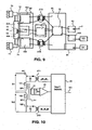
- the figure 10 represents a first diagram of a coupling device according to an embodiment of the invention with a multiplexing of input signals on a common signal transformer 14.
- the signal transformer 14 comprises: at least a first primary winding 151 for receiving a first input signal SI1 and at least first switching means 161 for cutting said first input signal SI1 and at least one second primary winding 152 to receive a second input signal SI2 and at least second means 162 switching circuit for cutting said second input signal SI2, and at least one secondary winding 21 for providing a secondary signal SD of representative of said first input signal SI1 or said second input signal SI2.
- a processing unit 25 selects first control means 271 of said first switching means 161 to provide a representative SO output signal of said first input signal SI1, or selects second control means 272 of the second switching means 162 to provide an output signal SO representative of said second input signal SI2.
- first control means 271 of said first switching means 161 to provide a representative SO output signal of said first input signal SI1
- second control means 272 of the second switching means 162 to provide an output signal SO representative of said second input signal SI2.
- the figure 11 represents a second diagram of a coupling device according to an embodiment of the invention with a multiplexing of input signals SI1, SI2, SI3, SI4 on a common signal transformer 14.
- the four signals SI1 to SI4 can be generated on measuring resistances 401, 402, 403, or 404 then cut by switching means respectively 161, 162, 163, and 164 and controlled by pulse transformers respectively 271, 272, 273 and 274 control means
- the switching means 274 are completely represented in one part while the others are represented by two-part blocks to simplify the scheme.
- the cutting of the input signals makes it possible to supply primary signals SP1, SP2, SP3, and SP4 to primary windings 151, 152, 153, and 154 of the signal transformer 14.
- the galvanic or electrical isolation is represented by a interrupted line 86.
- the secondary signal SD is applied to an amplifier 22 having a parameterizable amplification.
- the output signal of the amplifier is filtered by a low-pass filter 87 before being applied to the processing unit 25.
- the processing unit 25 comprises a signal sampler 88 for sampling a signal representative of a signal multiplexed secondary and provide values representative of each input signal, the sampling being synchronized with the selection of the control means.
- the amplifier 22 and the sampler 88 are referenced by a reference circuit 89.
- a microcontroller or a microprocessor located in the processing unit allows the supply of control signals of the switching means and the synchronization of the sampling serving as synchronous detection.
- the microprocessor 90 receiving the samples of the signal SD separates the different values into several output signals SO1, SO2, SO3 and SO4 representative respectively of the input signals SI1, SI2, SI3, and SI4.
- the processing means sequentially controls the selection of the control means to provide a sequentially representative multiplexed SO output signal of each input signal SI1 to SI4.
- the processing means can simultaneously control control means for providing an output signal SO representative of the sum of the input signals.
- the coupling device can be used in a four-pole type circuit breaker receiving signals representative of three-phase signals and a neutral conductor.
- the measuring resistors 401, 402, 403, or 404 are then current measurement shunts.
- a simultaneous control of the four channels can provide a signal SO representative of a differential current.
- simultaneous digital processing of the four channels by a processor may provide a signal SO representative of a differential current or the sum of the input signals.
- the Figures 12A to 12G represent signal curves in a device of the figure 11 . States of the different switching means 161 to 164 are represented on curves 91 to 94 of FIG. figure 12A . State 1 corresponds to a closed state of the corresponding switch and state 0 corresponds to the open state.
- the figure 12B shows a curve 95 representative of an example of an input signal SI1.
- the figure 12C shows a curve 96 representative of an example of an input signal SI2.
- the figure 12D shows a curve 97 representative of an example of an input signal SI3.
- the figure 12E shows a curve 98 representative of an example of an input signal SI4.
- the figure 12F shows a curve 99 representative of an example of secondary signal SD.
- the figure 12G shows a sampling of the secondary signal to separate the SD signal into four output signals SO1, SO2, SO3 and SO4 representative of the four input signals SI1, SI2, SI3, and SI4.
- the switch 161 is closed and the secondary signal SD becomes representative of the input signal SI1.
- the signal SD is sampled to have an output signal SO1 representative of the signal SI1.
- the switch 162 is closed and the secondary signal SD becomes representative of the input signal SI2.
- the signal SD is sampled to have an output signal SO2 representative of the signal SI2.
- the control of the switch 162 is completed.
- the switch 163 is closed and the secondary signal SD becomes representative of the input signal SI3.
- the signal SD is sampled to have an output signal SO3 representative of the signal SI3.
- the control of the switch 163 is completed.
- the switch 164 is closed and the secondary signal SD becomes representative of the input signal SI4.
- the signal SD is sampled to have an output signal SO4 representative of the signal SI4.
- the control of the switch 164 is complete.
- the cycle begins again by closing the switch 161, and sampling SD at time t14 to provide SO1.
- the delay D corresponds to the waiting time between the start of closing of the switches and the sampling of the secondary signal SD at the output of the signal transformer 14.
- the figure 13 represents a flow chart showing an acquisition cycle of a measurement sample.
- the processing unit selects the path to be measured. Then, in a step 101, an electronic switch of the switching means is closed. Then, after a delay D allowing the stabilization of the operation of the transformer, in particular avoiding parasitic oscillations at a step 102, the processing unit controls the sampling of a signal representative of the secondary signal SD at a step 103. sampling is performed after a predetermined delay D following the start of a control pulse closing switch means.
- the figure 14 represents an electrical apparatus diagram comprising a measuring device according to an embodiment of the invention.
- Such an electrical apparatus 104 comprises at least a measuring resistor 401 and 402, electrical power contacts 105 connected in series with said at least one measurement resistor, a mechanism 106 for opening the electrical contacts 105, and processing means 107 for protecting functions a relay 108 connected to said mechanism 106.
- the apparatus comprises a coupling device 110 as described above having at least one signal input connected to said at least one measuring resistor, and a signal output connected to the protection function processing means 107 for providing an output signal SO representative of a current flowing in said measurement resistor.
- the coupling device 110 may be the same as that of the figure 10 with signal multiplexing.
- Resistors 401 and 402 may be resistors of very low values such as electric shunts.
- control means of the switching means are preferably pulse transformers 27, 271, 272 having a primary winding 115 receiving the control signals and a secondary winding 116 for controlling means of switching. switching.
- the figure 15 represents a pulse transformer in printed form used in the control means of a coupling device according to an embodiment of the invention.
- the pulse transformer is an air transformer having a primary winding 115 on a first face 117 of a printed circuit 118 and a secondary winding 116 on a second face 119 of said printed circuit.
- the operating frequency is then very high to achieve very small winding sizes.
- each winding has thirteen turns with an outer dimension less than one centimeter on the side.
- the operating frequency of the control means is much greater than the switching frequency.
- the signals of control are then pulses or bursts of high frequency pulses provided during TC switching periods.
- the printed circuit may also be an etched circuit or any other circuit serving as support for example a ceramic support or alumina. Even in the printed form, the control transformers may have a magnetic circuit adapted to the shapes and dimensions of the circuit support.
- a circuit support 118 is advantageously composed of a polyimide material.
- the circuit support has a thickness (E) of between 3 and 80 ⁇ m.
- the measuring transformer may be an air transformer having at least one primary winding 15 on a first face of a circuit support 118 and a secondary winding 21 on a second face of said circuit support.
- the circuit support is composed of a polyimide material having a thickness (E) of between 3 and 80 ⁇ m.
- the figure 16 shows an assembly of two control transformers and a measurement transformer placed on the same insulating support with windings on each side of said circuit support.
- the circuit support is advantageously composed of a polyimide material having a thickness (E) of between 3 and 80 ⁇ m.
- FIGS 17 and 18 show variants of devices according to embodiments of the invention.
- the control means of the switching means are a double capacitive link 120 passing the pulses and blocking the DC or low frequency to ensure the galvanic isolation.
- the control signals are complementary to circulate a control current between the two links and ensure a common mode electrical isolation.
- said control means of the switching means comprise at least two capacitive coupling capacitors 501, 502 each having a first electrode 503 for receiving the control signals and a second electrode 504 for controlling switching means.
- the capacitors are made on a circuit support 505 composed of a polyimide material having a thickness of between 3 and 80 microns.
- said circuit support has on a first face the first electrodes 503 and on the second face the second electrodes 504 of said two coupling capacitors 501 and 502.
- control means of the switching means and the switching means are grouped into a micro electromagnetic component 122, preferably in the so-called MEMs technology.
- switching means may be used in particular field effect transistors, bipolar transistors, electromagnetically controlled switches, electrostatic or optical.
- the switching frequency of the input signal SI may depend on the size of the coupling transformer used and the transfer rate through said transformer. This switching frequency is advantageously related to the capabilities of the detection and sampling means.
- the coupling devices described above make it possible to measure any type of electrical signals, in particular currents, voltages, or several types in multiplexed mode on the same magnetic circuit of the signal transformer.
- the input signal can be provided by a voltage divider bridge.
- the electrical apparatus comprising the coupling device can be of any type. If the electrical apparatus includes electrical protection functions such as those of a relay or a circuit breaker trip, the measurement resistors are advantageously electric shunts. These shunts may be of the resistor or impedance type, for example inductance type.
Description
L'invention concerne un dispositif de couplage à isolement électrique comportant :
- au moins une entrée de signal d'entrée,
- une sortie de signal de sortie représentatif dudit signal d'entrée, et
- des moyens de transfert de signal à isolement électrique recevant le signal d'entrée et fournissant ledit signal de sortie,
- au moins un transformateur (14) de signal ayant au moins un enroulement primaire pour recevoir un signal primaire représentatif dudit signal d'entrée,
- des moyens de commutation pour découper le signal d'entrée et fournir ledit signal primaire représentatif dudit signal d'entrée audit enroulement primaire,
- des moyens de commande des moyens de commutation comportant une entrée de signal de commande recevant des signaux de commande pendant des périodes de commutation, et une sortie électriquement isolée de l'entrée de signaux de commande et connectée audits moyens de commutation pour commander le découplage de signal primaire pendant lesdites des périodes de commutation.
- at least one input signal input,
- an output signal output representative of said input signal, and
- electrically isolated signal transfer means receiving the input signal and providing said output signal,
- at least one signal transformer (14) having at least one primary winding for receiving a primary signal representative of said input signal,
- switching means for cutting off the input signal and providing said primary signal representative of said input signal to said primary winding,
- control means for the switching means having a control signal input receiving control signals during switching periods, and an output electrically isolated from the control signal input and connected to said switching means for controlling the decoupling of the control signal. primary signal during said switching periods.
L'invention concerne aussi un appareil électrique comportant un tel dispositif de couplage.The invention also relates to an electrical apparatus comprising such a coupling device.
Les dispositifs de couplage de signal de mesure à isolation électrique connus sont généralement réalisés avec une première partie 1 de traitement de signal d'entrée SI et une seconde partie 2 de traitement de signal de sortie SO. Un schéma d'un dispositif connu est représenté sur la
Dans d'autres schémas il peut y avoir deux alimentations indépendantes pour alimenter séparément la première partie et la seconde partie.In other schemes there may be two independent power supplies for separately powering the first part and the second part.
Les dispositifs de couplage de signal de mesure à isolation électrique connus de l'état de la technique nécessitant des circuits auxiliaires d'alimentation peuvent difficilement être intégrés dans des circuits ou des appareils de mesure de traitement de très faible encombrement. De plus, de tels dispositifs ont aussi l'inconvénient de consommer de l'énergie électrique les rendant incompatibles avec des applications à très faible consommation.Electrically isolated measurement signal coupling devices known from the state of the art requiring auxiliary supply circuits can hardly be integrated into very small processing circuit circuits or measuring devices. In addition, such devices also have the disadvantage of consuming electrical energy making them incompatible with applications with very low consumption.
Certains dispositifs comportent des transformateurs recevant un signal de mesure de courant découpé tel que représenté dans les documents
Un autre exemple est fourni dans le document
L'invention a pour but un dispositif de couplage de signal de mesure à isolation électrique ne nécessitant pas d'alimentation de la partie traitant le signal d'entrée et pouvant fonctionner normalement avec des écarts de température très importants, et un appareil comportant un tel dispositif.The object of the invention is to provide an electrically isolated measurement signal coupling device which does not require a power supply for the input signal processing part and which can operate normally with very large temperature differences, and an apparatus comprising such a device. device.
Dans un dispositif de couplage à isolement électrique selon l'invention, lesdits moyens de commande des moyens de commutation comportent des moyens de couplage par induction électromagnétique et/ou par liaison capacitive.In an electrically isolated coupling device according to the invention, said means for controlling the switching means comprise coupling means by electromagnetic induction and / or by capacitive link.
Ledit transformateur de signal comporte un enroulement de sortie connecté à des moyens de détection recevant un signal secondaire de sortie découpé et fournissant un signal de sortie représentatif du signal d'entrée.Said signal transformer has an output winding connected to detection means receiving a cut output secondary signal and providing an output signal representative of the input signal.
Dans une première variante, le découpage du signal d'entrée est unidirectionnel. Dans une seconde variante, le découpage du signal d'entrée est bidirectionnel ou avec inversion.In a first variant, the cutting of the input signal is unidirectional. In a second variant, the cutting of the input signal is bidirectional or with inversion.
Dans un premier mode de réalisation particulier, le transformateur de signal comporte deux enroulements primaires connectés avec des sens d'enroulement inversés, une première extrémité de chaque enroulement est reliée en un point commun des enroulements pour recevoir l'entrée de signal, des secondes extrémités des enroulements sont connectés à des premiers moyens de commutation et à des seconds moyens de commutation pour découper et orienter le signal d'entrée alternativement sur le premier et le second enroulement.In a first particular embodiment, the signal transformer has two primary windings connected with inverted winding directions, a first end of each winding is connected at a common point of the windings to receive the signal input, second ends. windings are connected to first switching means and second switching means for cutting and orienting the input signal alternately on the first and second windings.
De préférence, les moyens de commutation commutent des signaux d'entrée sur les enroulements primaires avec un recouvrement dès commandes en début et en fin de commutation.Preferably, the switching means switch input signals on the primary windings with a covering of commands at the beginning and end of switching.
Dans un second mode de réalisation particulier, le transformateur de signal comporte un enroulement primaire connecté à des moyens de commutation comportant quatre commutateurs électroniques connectés en pont à deux branches, des lignes extérieures du pont recevant le signal d'entrée et des branches intérieures du pont étant connectées audit enroulement primaire dudit transformateur de signal, lesdits commutateurs en pont étant commandés alternativement de manière croisée pour inverser le sens du signal primaire appliqué à l'enroulement primaire dudit transformateur de signal.In a second particular embodiment, the signal transformer comprises a primary winding connected to switching means comprising four electronic switches connected in bridge with two branches, external lines of the bridge receiving the input signal and inner branches of the bridge. being connected to audit primary winding of said signal transformer, said bridge switches being alternately cross-controlled to reverse the direction of the primary signal applied to the primary winding of said signal transformer.
Dans un troisième mode de réalisation particulier, le signal d'entrée est appliqué à un pont de deux résistances de mesure connectées en série, un point commun des résistances de mesure étant connecté à une première extrémité d'un enroulement primaire du transformateur de signal, une seconde extrémité dudit enroulement primaire du transformateur de signal étant connecté à une partie centrale commune d'un pont de commutation à deux commutateurs des moyens de commutation, des lignes externes des commutateurs dudit pont étant connectées sur les parties externes opposées au point commun du pont de résistances, les deux commutateurs fonctionnant de manière alternée pour inverser le sens du signal primaire appliqué à l'enroulement primaire dudit transformateur de signal.In a third particular embodiment, the input signal is applied to a bridge of two measurement resistors connected in series, a common point of the measurement resistors being connected to a first end of a primary winding of the signal transformer, a second end of said primary winding of the signal transformer being connected to a common central part of a switching bridge with two switches of the switching means, external lines of the switches of said bridge being connected to the external parts opposite to the common point of the bridge of resistors, the two switches operating alternately to reverse the direction of the primary signal applied to the primary winding of said signal transformer.
De préférence, les moyens de détection comportent des moyens de filtrage du signal de sortie découpé.Preferably, the detection means comprise means for filtering the cut output signal.
Dans un mode de réalisation préférentiel, les moyens de détection comportent des moyens de détection synchrones synchronisés avec la commande des moyens de commutation pour reconstituer un signal de sortie représentatif dudit signal d'entrée.In a preferred embodiment, the detection means comprise synchronous detection means synchronized with the control of the switching means for reconstituting an output signal representative of said input signal.
Avantageusement, le transformateur de signal comporte :
- au moins un premier enroulement primaire pour recevoir un premier signal d'entrée et au moins des premiers moyens de commutation pour découper ledit premier signal d'entrée
- au moins un second enroulement primaire pour recevoir un second signal d'entrée et au moins des seconds moyens de commutation pour découper ledit second signal d'entrée, et
- au moins un enroulement secondaire pour fournir un signal représentatif dudit premier signal d'entrée ou dudit second signal d'entrée.
- at least a first primary winding for receiving a first input signal and at least first switching means for cutting said first input signal
- at least one second primary winding for receiving a second input signal and at least one second switching means for cutting said second input signal, and
- at least one secondary winding for providing a signal representative of said first input signal or said second input signal.
Avantageusement, le dispositif comporte des moyens de traitement :
- pour sélectionner des premiers moyens de commande desdits premiers moyens de commutation pour fournir un signal de sortie représentatif dudit premier signal d'entrée, ou
- pour sélectionner des seconds moyens de commande desdits seconds moyens de commutation pour fournir un signal de sortie représentatif dudit second signal d'entrée.
- for selecting first means for controlling said first switching means to provide an output signal representative of said first input signal, or
- for selecting second means for controlling said second switching means to provide an output signal representative of said second input signal.
De préférence, les moyens de traitement commandent séquentiellement la sélection des moyens de commande pour fournir un signal de sortie multiplexé représentatif séquentiellement de chaque signal d'entrée.Preferably, the processing means sequentially controls the selection of the control means to provide a multiplexed output signal sequentially representative of each input signal.
Avantageusement, les moyens de traitement commandent simultanément des moyens de commande pour fournir un signal de sortie représentatif de la somme des signaux d'entrée.Advantageously, the processing means simultaneously control control means to provide an output signal representative of the sum of the input signals.
De préférence, les moyens de traitement comportent des moyens d'échantillonnage de signal pour échantillonner un signal de sortie représentatif d'un signal secondaire multiplexé et fournir des valeurs représentatives de chaque signal d'entrée, l'échantillonnage étant synchroniser avec la sélection des moyens de commande.Preferably, the processing means comprise signal sampling means for sampling an output signal representative of a multiplexed secondary signal and providing values representative of each input signal, the sampling being synchronized with the selection of the means. control.
De préférence, l'échantillonnage est effectué après un délai prédéterminé suivant le début d'une impulsion de commande fermant des moyens de commutation.Preferably, the sampling is performed after a predetermined delay following the start of a control pulse closing switching means.
De préférence, les moyens de traitement activent la commande des moyens de commande pendant des périodes de durée courte et arrêtent la commande des moyens de commande pendant des périodes de durée longue.Preferably, the processing means activate the control of the control means during periods of short duration and stop the control of the control means for periods of long duration.
Dans un mode de réalisation préféré, lesdits moyens de commande des moyens de commutation comportent au moins un transformateur de commande ayant un enroulement primaire recevant les signaux de commande et un enroulement secondaire pour commander des moyens de commutation.In a preferred embodiment, said means for controlling the switching means comprise at least one control transformer having a primary winding receiving the control signals and a secondary winding for controlling switching means.
De préférence, au moins un transformateur de commande des moyens de commande est un transformateur à air ayant un enroulement primaire sur une première face d'un support de circuit et un enroulement secondaire sur une seconde face dudit support de circuit.Preferably, at least one control transformer of the control means is an air transformer having a primary winding on a first face of a circuit support and a secondary winding on a second face of said circuit support.
De préférence, le support de circuit est composé d'un matériau polyimide. Avantageusement, le support de circuit a une épaisseur comprise entre 3 et 80 µm.Preferably, the circuit support is composed of a polyimide material. Advantageously, the circuit support has a thickness of between 3 and 80 μm.
Dans un autre mode de réalisation, le transformateur de mesure est un transformateur à air ayant au moins un enroulement primaire sur une première face d'un support de circuit et un enroulement secondaire sur une seconde face dudit support de circuit.In another embodiment, the measurement transformer is an air transformer having at least one primary winding on a first face of a circuit carrier and a secondary winding on a second face of said circuit carrier.
Avantageusement, le support de circuit est composé d'un matériau polyimide et a une épaisseur comprise entre 3 et 80 µm.Advantageously, the circuit support is composed of a polyimide material and has a thickness of between 3 and 80 μm.
Dans un autres mode de réalisation, ledit au moins un transformateur de commande et au moins un transformateur de mesure sont placés sur un même support isolant avec des enroulements de chaque coté dudit support de circuit.In another embodiment, said at least one control transformer and at least one measuring transformer are placed on the same insulating support with windings on each side of said circuit support.
Avantageusement, le support de circuit est composé d'un matériau polyimide et a une épaisseur comprise entre 3 et 80 µm.Advantageously, the circuit support is composed of a polyimide material and has a thickness of between 3 and 80 μm.
Dans un autre mode de réalisation, lesdits moyens de commande des moyens de commutation comportent au moins deux condensateurs de couplage capacitif ayant chacun une première électrode pour recevoir les signaux de commande et une seconde électrode pour commander des moyens de commutation.In another embodiment, said means for controlling the switching means comprise at least two capacitive coupling capacitors each having a first electrode for receiving the control signals and a second electrode for controlling switching means.
Avantageusement, un support de circuit composé d'un matériau polyimide et ayant une épaisseur comprise entre 3 et 80 µm, ledit support de circuit a sur une première face les premières électrodes desdits deux condensateurs de couplage et sur la seconde face les secondes électrodes desdits deux condensateurs de couplage.Advantageously, a circuit support composed of a polyimide material and having a thickness of between 3 and 80 μm, said circuit support has on a first face the first electrodes of said two coupling capacitors and on the second face the second electrodes of said two coupling capacitors.
Dans un autres mode de réalisation, le dispositif de mesure comporte des moyens de commande des moyens de commutation et les moyens de commutation groupés en un micro composant électromagnétique de type Mem's.In another embodiment, the measuring device comprises means for controlling the switching means and the switching means grouped into an electromagnetic micro-component of Mem's type.
Avantageusement, le dispositif comporte un shunt électrique connecté aux entrées de signal pour la mesure d'un courant électrique, le signal de sortie étant représentatif d'un courant électrique circulant dans ledit shunt.Advantageously, the device comprises an electrical shunt connected to the signal inputs for measuring an electric current, the output signal being representative of an electric current flowing in said shunt.
Un appareil électrique selon l'invention comportant :
- au moins une résistance de mesure,
- des contacts électriques de puissance connectés en série avec ladite au moins une résistance de mesure,
- un mécanisme de commande d'ouverture desdits contacts électriques, et
- des moyens de traitement de fonctions de protection commandant un relais relié audit mécanisme,
- au moins une entrée de signal connectée à ladite au moins une résistance de mesure, et
- une sortie de signal connectée aux moyens de traitement de fonction de protection pour fournir un signal représentatif d'un courant circulant dans ladite au moins une résistance de mesure.
- at least one measuring resistor,
- electrical power contacts connected in series with said at least one measuring resistor,
- a mechanism for controlling the opening of said electrical contacts, and
- protection function processing means controlling a relay connected to said mechanism,
- at least one signal input connected to said at least one measurement resistor, and
- a signal output connected to the protection function processing means for providing a signal representative of a current flowing in said at least one measurement resistor.
D'autres avantages et caractéristiques ressortiront plus clairement de la description qui va suivre, de modes particuliers de réalisation de l'invention, donnés à titre d'exemples non limitatifs, et représentés aux dessins annexés sur lesquels :
- la
figure 1 représente un schéma d'un dispositif de couplage de signaux électrique à isolement électrique de l'état de la technique ; - la
figure 2 représente un schéma d'un dispositif de couplage de signaux électriques selon un premier mode de réalisation de l'invention ; - la
figure 3 représente un schéma d'un dispositif selon lafigure 2 avec une commande à découpage par transistors; - la
figure 4 représente un premier schéma d'un dispositif dé couplage selon un mode de réalisation de l'invention de type découpage avec inversion ; - les
figures 5A à 5G représentent des chronogrammes de signaux dans un dispositif selon le mode de réalisation de lafigure 4 ; - les
figures 6 représentent des variantes de dispositifs de couplage selon des modes de réalisation de l'invention de type découpage avec inversion ;et 7 - les
figures 8A à 8C représentent des courbes de signaux dans des dispositifs de couplage selon des modes de réalisation de l'invention à découpage bidirectionnel ; - la
figure 9 représente un mode de réalisation d'un dispositif de couplage de signaux électriques selon un mode de réalisation de l'invention du schéma de lafigure 7 ; - la
figure 10 représente un premier schéma d'un dispositif de couplage selon un mode de réalisation de l'invention avec un multiplexage de signaux d'entrée sur un transformateur de signal commun ; - la
figure 11 représente un second schéma d'un dispositif de couplage selon un mode de réalisation de l'invention avec un multiplexage de signaux d'entrée sur un transformateur de signal commun ; - les
figures 12A à 12G représentent des courbes de signaux dans un dispositif de lafigure 11 ; - la
figure 13 représente un organigramme montrant un cycle d'acquisition d'échantillon de mesure ; - la
figure 14 représente un schéma d'un appareil électrique comportant un dispositif de mesure selon un mode réalisation l'invention ; - la
figure 15 représente un transformateur d'impulsion sous forme imprimée utilisé dans les moyens de commande d'un dispositif de couplage selon un mode réalisation de l'invention ; - la
figure 16 représente un groupement de transformateurs d'impulsion et de transformateur de mesure sous forme imprimée utilisé dans un dispositif de couplage selon un mode de réalisation de l'invention ; - les
figures 17 et 18 montrent des variantes de dispositifs selon des modes de réalisation.
- the
figure 1 represents a diagram of an electrical isolation electrical signal coupling device of the state of the art; - the
figure 2 represents a diagram of an electrical signal coupling device according to a first embodiment of the invention; - the
figure 3 represents a diagram of a device according to thefigure 2 with a transistor switching control; - the
figure 4 represents a first diagram of a coupling device according to an embodiment of the invention of type with inversion cutting; - the
Figures 5A to 5G represent timing diagrams of signals in a device according to the embodiment of thefigure 4 ; - the
Figures 6 and 7 represent variants of coupling devices according to embodiments of the invention of the type with inversion cutting; - the
Figures 8A to 8C represent signal curves in coupling devices according to embodiments of the bidirectional switching invention; - the
figure 9 represents an embodiment of an electrical signal coupling device according to an embodiment of the invention of the diagram of thefigure 7 ; - the
figure 10 represents a first diagram of a coupling device according to an embodiment of the invention with a multiplexing of input signals on a common signal transformer; - the
figure 11 represents a second scheme of a coupling device according to an embodiment of the invention with a multiplexing of input signals on a common signal transformer; - the
Figures 12A to 12G represent signal curves in a device of thefigure 11 ; - the
figure 13 represents a flowchart showing a measuring sample acquisition cycle; - the
figure 14 represents a diagram of an electrical apparatus comprising a measuring device according to an embodiment of the invention; - the
figure 15 represents a pulse transformer in printed form used in the control means of a coupling device according to an embodiment of the invention; - the
figure 16 represents a group of pulse transformers and measuring transformers in printed form used in a coupling device according to one embodiment of the invention; - the
Figures 17 and 18 show variants of devices according to embodiments.
La
Sur la
Le signal de commande SC des moyens de commutation est fournit de préférence par un générateur 24 de signaux de découpage situé dans la seconde partie 2 de traitement de signal. De préférence, le module 23 de traitement et le générateur de signaux 24 de commande sont disposés dans une même unité de traitement 25 et alimentés par un même circuit d'alimentation 26. Ce circuit d'alimentation 26 peut alimenter aussi l'amplificateur 22. Les signaux de commande sont appliqués à un transformateur 27 d'impulsion des moyens de commande isolés. La sortie des moyens de commande peut comporter un circuit de conditionnement 28 de signaux comportant par exemple une diode 29 et un condensateur 30 pour être adapter aux moyens de commutation 16.The control signal SC of the switching means is preferably provided by a
Sur la
Si le signal d'entrée a une très faible tension, inférieure par exemple à 0,6 volt, un seul transistor 31 à effet de champ peut suffire. Dans cette zone le transistor fonctionne de manière bidirectionnelle et la diode associée n'est pas passante en polarisation directe.If the input signal has a very low voltage, for example less than 0.6 volts, a single field effect transistor 31 may suffice. In this zone, the transistor operates bidirectionally and the associated diode is not conducting in direct polarization.
Le dispositif de couplage peu fonctionner en mode de découpage du signal d'entrée unidirectionnel en découpant sur des ordres de commande consécutifs le signal d'entrée dans la même polarité et en l'appliquant aussi avec la même polarité sur l'enroulement primaire du transformateur de signal.The coupling device can operate in the unidirectional input signal cutting mode by cutting the input signal in the same polarity on consecutive control commands and also applying it with the same polarity on the primary winding of the transformer. of signal.
Pour améliorer le fonctionnement du transformateur de signal 14, le découpage du signal d'entrée peut être avantageusement bidirectionnel. Dans ce cas, le signal d'entrée est découpé et inversé à chaque ordre de commande pour fournir sur un circuit d'induction primaire du transformateur de signal 14 un signal primaire ayant des sens d'inductions consécutifs inversés. Ainsi, un circuit magnétique de couplage du transformateur de signal est magnétisé dans un sens puis démagnétisé et remagnétisé dans un autre sens selon les ordres de commande pour contrôler la rémanence dudit circuit magnétique et améliorer l'efficacité du transfert de signal entre le primaire et le secondaire du transformateur 14.To improve the operation of the
La
Les
A un instant t1, l'interrupteur 16A est commandé en fermeture alors que l'interrupteur 16B. vient de s'ouvrir. L'enroulement 15A reçoit le signal d'entrée SI. Il génère un courant I15A et une induction magnétique croissante I15. Cette induction génère sur le secondaire du transformateur 21 un signal de sortie égale à la dérivée du flux, donc un signal positif SD. A un instant t2, l'interrupteur 16B est commandé en fermeture, alors que l'interrupteur 16A est commandé en ouverture. Un courant I15B circule dans l'enroulement 15B. Le courant I15A s'annule. L'induction magnétique résultante représentée par I15 décroît parce que l'enroulement 15B est bobiné en sens contraire de l'enroulement 15A. Le signal sur le secondaire du transformateur SD devient négatif. Les commutations alternatives des interrupteurs 16A et 16B induisent une induction magnétique sans discontinuité dans le transformateur 14 et génèrent ainsi un signal SD alternative à composante continue nulle.At a time t1, the
Avec un tel dispositif, les courants d'induction dans le primaire ne sont jamais interrompus et les perturbations dues aux commutations dans les enroulements primaires ne sont pas induites dans le signal secondaire de sortie SD. Le signal de sortie SD peut être redressé pour fournir un signal de même signe que le signal primaire. Une période de découpage TC peut être définie, entre le début de la conduction et la fin de la conduction d'un interrupteur 16, par exemple entre les instant t1 et t2.With such a device, the induction currents in the primary are never interrupted and the disturbances due to switching in the primary windings are not induced in the secondary output signal SD. The output signal SD may be rectified to provide a signal with the same sign as the primary signal. A switching period TC can be defined between the beginning of the conduction and the end of the conduction of a
La
La
Les
Pour limiter la consommation électrique du dispositif, les moyens de traitement 25 peuvent activer la commande des moyens de commande pendant des périodes de durée courte et arrêter la commande des moyens de commande pendant des périodes plus longues d'inactivité. Par exemple, dans le schéma de la
La
Pour des mesures de plusieurs signaux de tension ou courant il est possible d'utiliser parallèlement plusieurs dispositifs tels que décrits ci-dessus. Cependant, dans des modes de réalisation particuliers de l'invention le transformateur de signal fait partie d'un ensemble de multiplexage.For measurements of several voltage or current signals it is possible to use several devices as described above in parallel. However, in particular embodiments of the invention the signal transformer is part of a multiplexing set.
La
La
De préférence, les moyens de traitement commandent séquentiellement la sélection des moyens de commande pour fournir un signal de sortie SO multiplexé représentatif séquentiellement de chaque signal d'entrée SI1 à SI4. Avantageusement, les moyens de traitement peuvent commander simultanément des moyens de commande pour fournir un signal de sortie SO représentatif de la somme des signaux d'entrée.Preferably, the processing means sequentially controls the selection of the control means to provide a sequentially representative multiplexed SO output signal of each input signal SI1 to SI4. Advantageously, the processing means can simultaneously control control means for providing an output signal SO representative of the sum of the input signals.
Avec un schéma tel que celui de la
Dans un autre mode de réalisation, un traitement numérique simultané des quatre voies par un processeur peut fournir un signal SO représentatif d'un courant différentiel ou de la somme des signaux d'entrée.In another embodiment, simultaneous digital processing of the four channels by a processor may provide a signal SO representative of a differential current or the sum of the input signals.
Les
A un instant t1, l'interrupteur 161 est fermé et le signal secondaire SD devient représentatif du signal d'entée SI1. Après un délai D permettant au transformateur 14 d'avoir un fonctionnement stable, à un instant t2, le signal SD est échantillonné pour avoir un signal de sortie SO1 représentatif du signal SI1. A la fin de la commande de l'interrupteur 161, à un instant t3, il n'y à plus de signal au primaire du transformateur, et le signal secondaire passe à une valeur nulle. A un instant t4, l'interrupteur 162 est fermé et le signal secondaire SD devient représentatif du signal d'entée SI2. Après un délai D permettant au transformateur 14 d'avoir un fonctionnement stable, à un instant t5, le signal SD est échantillonné pour avoir un signal de sortie SO2 représentatif du signal SI2. A un instant t6, la commande de l'interrupteur 162 est terminée. Puis, à un instant t7, l'interrupteur 163 est fermé et le signal secondaire SD devient représentatif du signal d'entée SI3. Après un délai D permettant au transformateur 14 d'avoir un fonctionnement stable, à un instant t8, le signal SD est échantillonné pour avoir un signal de sortie SO3 représentatif du signal SI3. A un instant t9, la commande de l'interrupteur 163 est terminée. Enfin, à un instant t10, l'interrupteur 164 est fermé et le signal secondaire SD devient représentatif du signal d'entée SI4. Après un délai D permettant au transformateur 14 d'avoir un fonctionnement stable, à un instant t11, le signal SD est échantillonné pour avoir un signal de sortie SO4 représentatif du signal SI4. A un instant t12, la commande de l'interrupteur 164 est terminée. A un instant t13, le cycle recommence en fermant l'interrupteur 161, et en échantillonnant SD à l'instant t14 pour fournir SO1. Le délai D correspond au temps d'attente entre le début de fermeture des interrupteurs et l'échantillonnage du signal secondaire SD en sortie du transformateur de signal 14.At a time t1, the
La
La
Dans les modes de réalisation décrits ci-dessus, les moyens de commande des moyens de commutation sont de préférence des transformateurs 27, 271, 272 à impulsions ayant un enroulement primaire 115 recevant les signaux de commande et un enroulement secondaire 116 pour commander des moyens de commutation.In the embodiments described above, the control means of the switching means are preferably
Lorsque les moyens de commande des moyens de commutation sont des transformateurs à impulsion, la fréquence de fonctionnement propre peut être très élevée pour réduire la taille ou supprimer le circuit magnétique. La commande peut prendre la forme de salves de signaux à fréquence très élevée durant une période de commande. La
Dans un cas particulier de réalisation, le transformateur de mesure peut être un transformateur à air ayant au moins un enroulement primaire 15 sur une première face d'un support de circuit 118 et un enroulement secondaire 21 sur une seconde face dudit support de circuit. Avantageusement, le support de circuit est composé d'un matériau polyimide d'une épaisseur (E) comprise entre 3 et 80 µm.In a particular embodiment, the measuring transformer may be an air transformer having at least one primary winding 15 on a first face of a
La
Les
Sur la
Sur la
Plusieurs types de moyens de commutation peuvent être utilisés notamment des transistors à effet de champ, de transistors bipolaires, des commutateurs à commande électromagnétique, électrostatique ou optique.Several types of switching means may be used in particular field effect transistors, bipolar transistors, electromagnetically controlled switches, electrostatic or optical.
La fréquence de découpage du signal d'entrée SI peut dépendre de la taille du transformateur de couplage utilisé et du taux de transfert à travers ledit transformateur. Cette fréquence de découpage est avantageusement liée aux capacités des moyens de détection et d'échantillonnage.The switching frequency of the input signal SI may depend on the size of the coupling transformer used and the transfer rate through said transformer. This switching frequency is advantageously related to the capabilities of the detection and sampling means.
Les dispositifs de couplage décrits ci-dessus permettent dé mesurer tout type de signaux électriques, notamment des courants, des tensions, ou plusieurs types en mode multiplexé sur un même circuit magnétique du transformateur de-signal. Pour la mesure de tension, le signal d'entrée peut être fourni par un pont diviseur de tension.The coupling devices described above make it possible to measure any type of electrical signals, in particular currents, voltages, or several types in multiplexed mode on the same magnetic circuit of the signal transformer. For voltage measurement, the input signal can be provided by a voltage divider bridge.
Les appareils électriques comprenant le dispositif de couplage peuvent être de tout type. Si l'appareil électrique comporte des fonctions de protection électrique comme celles d'un relais ou d'un déclencheur de disjoncteur, les résistances de mesures sont avantageusement des shunts électriques. Ces shunts peuvent être de type résistance ou impédance par exemple à inductance.The electrical apparatus comprising the coupling device can be of any type. If the electrical apparatus includes electrical protection functions such as those of a relay or a circuit breaker trip, the measurement resistors are advantageously electric shunts. These shunts may be of the resistor or impedance type, for example inductance type.
Claims (15)
- Coupling device with electrical insulation comprising:- at least one input signal (SI) input,- an output signal (SO) output, the output signal being representative of the said input signal, and- signal transfer means with electrical insulation receiving the input signal and providing the said output signal,- at least one signal transformer (14) having at least one primary winding (15, 15A, 15B, 151, 152, 153, 154) to receive a primary signal (SP, SP1, SP2, SP3, SP4) representative of the said input signal (SI, SIA, SIB, SI1, SI2, SI3, SI4),- switching means (16, 16A, 16B, 161, 162, 163, 164, 31, 32) to cut the input signal and provide the said primary signal representative of the said input signal to the said primary winding,- means (17, 17A, 17B, 27, 27A, 27B, 271, 272, 273, 274) of control of the switching means comprising a control signal input (SC) receiving control signals during switching periods (TC), and an output electrically insulated from the control signals input and connected to the said switching means (16, 16A, 16B, 161, 162, 163, 164, 31, 32) to control the primary signal cutting during the said switching periods (TC), characterized in that the said means of control of the switching means comprise means of coupling by electromagnetic induction and/or by capacitive link.
- Coupling device according to Claim 1, characterized in that the signal transformer (14) comprises two primary windings (15A, 15B) connected with reversed directions of winding, a first end of each winding is linked at a common point of the windings to receive the signal input, second ends of the windings are connected to first switching means (16A) and to second switching means (16B) to cut and orient the input signal (SI, SIA, SIB) alternately on the first and the second winding.
- Coupling device according to Claim 1, characterized in that the signal transformer (14) comprises a primary winding (15) connected to switching means (16) comprising four electronic switches (16A1, 16A2, 16B1, 16B2) connected bridge-like with two branches (50, 51), exterior lines of the bridge receiving the input signal (SI) and interior branches (53) of the bridge being connected to the said primary winding (15) of the said signal transformer, the said bridge-like switches being controlled alternately in a crossed manner so as to reverse the direction of the primary signal (SP) applied to the primary winding (15) of the said signal transformer.
- Coupling device according to Claim 1, characterized in that the input signal (SI, SIA, SIB) is applied to a bridge of two measurement resistors (40A, 40B) connected in series, a common point (54) of the measurement resistors being connected to a first end of a primary winding (15) of the signal transformer (14), a second end of the said primary winding (15) of the signal transformer being connected to a common central part (55) of a switching bridge with two switches (16A, 16B) of the switching means, external lines (57, 58) of the switches of the said bridge being connected to the external parts (59, 60) opposite from the common point of the bridge of resistors, the two switches operating in an alternate manner so as to reverse the direction of the primary signal (SP) applied to the primary winding (15) of the said signal transformer (14).
- Coupling device according to any one of Claims 1 to 4, characterized in that the signal transformer (14) comprises:- at least one first primary winding (151) to receive a first input signal (SI1) and at least first switching means (161) to cut the said first input signal- at least one second primary winding (152) to receive a second input signal (SI2) and at least second switching means (162) to cut the said second input signal, and- at least one secondary winding (21) to provide a signal (SD) representative of the said first input signal (SI1) or of the said second input signal (SI2).
- Coupling device according to Claim 5, characterized in that it comprises processing means (25) so as:- to select first means (271) of control of the said first switching means (161) so as to provide an output signal (SO) representative of the said first input signal (SI1), or- to select second means (272) of control of the said second switching means (162) so as to provide an output signal (SO) representative of the said second input signal (SI2).
- Coupling device according to one of Claims 5 and 6, characterized in that the processing means (25) sequentially control the selection of the means of control so as to provide a multiplexed output signal (SO) representative sequentially of each input signal (SI1, SI2, SI3, SI4) and/or they simultaneously control means of control so as to provide an output signal (SO) representative of the sum of the input signals.
- Coupling device according to any one of Claims 5 to 7, characterized in that the processing means (25) activate the control of the means of control during periods of short duration and stop the control of the means of control during periods of long duration.
- Coupling device according to any one of Claims 1 to 8, characterized in that the said means of control of the switching means comprise at least one control transformer (27, 271, 272, 273, 274, 27A, 27B) having a primary winding receiving the control signals and a secondary winding to control switching means, the said transformer being an air-type transformer having a primary winding (115) on a first face (117) of a circuit support (118) and a secondary winding (116) on a second face (119) of the said circuit support.
- Coupling device according to Claim 9, characterized in that the circuit support is composed of a polyimide material having a thickness (E) of between 3 and 80 µm.
- Coupling device according to any one of Claims 1 to 10, characterized in that the measurement transformer is an air-type transformer having at least one primary winding (15) on a first face (117) of a circuit support (118) and a secondary winding (21) on a second face (119) of the said circuit support, the said circuit support being composed of a polyimide material having a thickness (E) of between 3 and 80 µm.
- Coupling device according to any one of Claims 9 to 11, characterized in that the said at least one control transformer (371, 372) and at least one measurement transformer (14) are placed on one and the same insulating support (118) with windings (116, 116, 15, 21) on each side of the said circuit support, the said circuit support being composed of a polyimide material having a thickness (E) of between 3 and 80 µm.
- Coupling device according to any one of Claims 1 to 12, characterized in that the said means of control of the switching means comprise at least two capacitors (501, 502) for capacitive coupling each having a first electrode (503) to receive the control signals and a second electrode (504) to control switching means.
- Coupling device according to any one of Claims 1 to 13, characterized in that it also comprises means of control of the switching means (17) and the switching means (16) grouped into an electromagnetic micro component (122) of Mem's type.
- Electrical apparatus comprising:- at least one measurement resistor (40, 40A, 40B, 401, 402),- power electrical contacts (105) connected in series with the said at least one measurement resistor,- a mechanism (106) for controlling opening of the said electrical contacts, and- means (107) for processing protection functions controlling a relay (108) linked to the said mechanism,characterized in that it comprises at least one coupling device according to any one of Claims 1 to 14 having:- at least one signal input (SI1, SI2) connected to the said at least one measurement resistor (40, 40A, 40B, 401, 402), and- a signal output (SO) connected to the protection function processing means (25) to provide a signal (SO) representative of a current flowing in the said at least one measurement resistor.
Applications Claiming Priority (2)
| Application Number | Priority Date | Filing Date | Title |
|---|---|---|---|
| FR0611006A FR2910162B1 (en) | 2006-12-18 | 2006-12-18 | ELECTRICALLY INSULATED MEASURING SIGNAL COUPLING DEVICE AND ELECTRICAL APPARATUS COMPRISING SUCH A DEVICE |
| PCT/FR2007/002026 WO2008087276A2 (en) | 2006-12-18 | 2007-12-10 | Electrically insulated device for coupling measuring signals, and electrical appliance comprising such a device |
Publications (2)
| Publication Number | Publication Date |
|---|---|
| EP2102994A2 EP2102994A2 (en) | 2009-09-23 |
| EP2102994B1 true EP2102994B1 (en) | 2015-11-11 |
Family
ID=38234338
Family Applications (1)
| Application Number | Title | Priority Date | Filing Date |
|---|---|---|---|
| EP07871821.0A Active EP2102994B1 (en) | 2006-12-18 | 2007-12-10 | Electrically insulated device for coupling measuring signals, and electrical appliance comprising such a device |
Country Status (7)
| Country | Link |
|---|---|
| US (1) | US8390270B2 (en) |
| EP (1) | EP2102994B1 (en) |
| CN (1) | CN101563856B (en) |
| BR (1) | BRPI0721075B1 (en) |
| ES (1) | ES2558878T3 (en) |
| FR (1) | FR2910162B1 (en) |
| WO (1) | WO2008087276A2 (en) |
Families Citing this family (11)
| Publication number | Priority date | Publication date | Assignee | Title |
|---|---|---|---|---|
| FR2910173B1 (en) * | 2006-12-18 | 2012-05-04 | Schneider Electric Ind Sas | ELECTRIC ISOLATION CURRENT MEASURING DEVICE, ELECTRONIC TRIGGER, AND CIRCUIT BREAKER COMPRISING SUCH A DEVICE |
| US7889041B2 (en) * | 2007-11-05 | 2011-02-15 | Schweitzer Engineering Laboratories, Inc. | Systems and methods for forming an isolated transformer |
| EP2547000B1 (en) * | 2010-03-09 | 2017-12-27 | Toyota Jidosha Kabushiki Kaisha | Signal transmitting apparatus |
| US20120085176A1 (en) * | 2010-10-07 | 2012-04-12 | Ray Morales | Analog strain gauge conditioning system for space environment |
| DE112015004340T5 (en) | 2014-09-24 | 2017-06-01 | Analog Devices, Inc. | Circuits and systems for multiplexed communication via an isolator |
| CN105807117B (en) * | 2014-12-29 | 2020-01-31 | 苏州普源精电科技有限公司 | Current sensing circuit for current measuring probe and current measuring probe thereof |
| US9829531B2 (en) * | 2015-10-23 | 2017-11-28 | Maxim Integrated Products, Inc. | Dual galvanic isolation barriers and monitoring systems and methods |
| EP3431978B1 (en) * | 2017-07-17 | 2020-09-02 | Mettler-Toledo GmbH | Method and device for monitoring and/or determining the condition of a measuring probe |
| CN109347522B (en) * | 2018-09-20 | 2021-09-28 | 刘泰康 | Electromagnetic induction type information isolation transmission system based on magnetic line medium |
| JP7101152B2 (en) | 2019-09-06 | 2022-07-14 | 株式会社東芝 | Electronic circuits, current measuring devices, and methods |
| JP2022022716A (en) | 2020-07-02 | 2022-02-07 | 株式会社東芝 | Electronic circuit, current measurement device, voltage measurement device, power converter, and inverter |
Family Cites Families (17)
| Publication number | Priority date | Publication date | Assignee | Title |
|---|---|---|---|---|
| US3667289A (en) * | 1970-01-05 | 1972-06-06 | Saab Scania Ab | Apparatus for testing automobiles |
| US4042871A (en) * | 1975-11-14 | 1977-08-16 | Ecc Corporation | Conversion system with overcurrent protection and start-up circuitry |
| DE2636677A1 (en) * | 1976-08-14 | 1978-02-16 | Bosch Gmbh Robert | MEASURING DEVICE FOR DIGITAL MEASUREMENT OF SPECIFIC DATA OF IGNITION SYSTEMS FOR COMBUSTION MACHINERY |
| HU196513B (en) * | 1985-11-18 | 1988-11-28 | Miki Merestechnikai Fejlesztoe | Apparatus for measuring voltage by sampling |
| EP0356248B1 (en) * | 1988-08-24 | 1995-09-06 | Liaisons Electroniques-Mecaniques Lem S.A. | A current sensor |
| FR2664442B1 (en) * | 1990-07-03 | 1996-04-26 | Merlin Gerin | ELECTRONIC TRIGGER HAVING IMPROVED LONG DELAY FUNCTION. |
| FR2690752A1 (en) * | 1992-04-30 | 1993-11-05 | Artus | Analog data signals acquisition system - time multiplexes sampled input signals to respective primaries of transformer, and detects each signal using single secondary winding for D=A conversion. |
| FR2725320B1 (en) * | 1994-09-29 | 1996-10-31 | Schneider Electric Sa | TRIGGERING DEVICE HAVING AT LEAST ONE CURRENT TRANSFORMER |
| FR2757699B1 (en) * | 1996-12-23 | 1999-01-29 | Schneider Electric Sa | ELECTRONIC TRIGGER COMPRISING, IN SERIES, FINITE AND INFINITE IMPULSE RESPONSE FILTERS |
| FR2762156B1 (en) * | 1997-04-15 | 1999-06-11 | Schneider Electric Sa | SELECTIVE ELECTRONIC TRIGGER, CIRCUIT BREAKER CONTAINING SUCH A TRIGGER AND SELECTIVE TRIGGERING PROCESS |
| US6259246B1 (en) * | 1999-05-04 | 2001-07-10 | Eaton Corporation | Load sensing apparatus and method |
| JP4269515B2 (en) * | 2000-12-25 | 2009-05-27 | パナソニック電工株式会社 | Electric quantity detection sensor |
| FR2830386B1 (en) * | 2001-10-02 | 2003-12-05 | Schneider Electric Ind Sa | COUPLING DEVICE FOR A LOW FLOW RATE CARRIER TRANSMISSION SYSTEM |
| US7259545B2 (en) * | 2003-02-11 | 2007-08-21 | Allegro Microsystems, Inc. | Integrated sensor |
| US6885184B1 (en) * | 2004-03-31 | 2005-04-26 | Asco Power Technologies, L.P. | Galvanically isolated voltage sensing circuit |
| FR2891093B1 (en) * | 2005-09-16 | 2007-10-26 | Schneider Electric Ind Sas | ELECTRONIC TRIGGER WITH MONITORING MEANS, CIRCUIT BREAKER COMPRISING SUCH A TRIGGER AND SURVEILLANCE METHOD. |
| US7876086B2 (en) * | 2008-02-28 | 2011-01-25 | International Components Corporation | Current measuring device for measuring the electrical current flowing in an electrical conductor electrically isolated from the current measuring device |
-
2006
- 2006-12-18 FR FR0611006A patent/FR2910162B1/en not_active Expired - Fee Related
-
2007
- 2007-12-10 WO PCT/FR2007/002026 patent/WO2008087276A2/en active Application Filing
- 2007-12-10 EP EP07871821.0A patent/EP2102994B1/en active Active
- 2007-12-10 BR BRPI0721075A patent/BRPI0721075B1/en active IP Right Grant
- 2007-12-10 ES ES07871821.0T patent/ES2558878T3/en active Active
- 2007-12-10 US US12/312,675 patent/US8390270B2/en active Active
- 2007-12-10 CN CN2007800466353A patent/CN101563856B/en active Active
Also Published As
| Publication number | Publication date |
|---|---|
| EP2102994A2 (en) | 2009-09-23 |
| CN101563856A (en) | 2009-10-21 |
| FR2910162A1 (en) | 2008-06-20 |
| WO2008087276A2 (en) | 2008-07-24 |
| BRPI0721075B1 (en) | 2020-02-04 |
| US8390270B2 (en) | 2013-03-05 |
| US20100060261A1 (en) | 2010-03-11 |
| WO2008087276A3 (en) | 2008-10-30 |
| CN101563856B (en) | 2013-11-13 |
| FR2910162B1 (en) | 2009-12-11 |
| BRPI0721075A2 (en) | 2014-04-15 |
| ES2558878T3 (en) | 2016-02-09 |
Similar Documents
| Publication | Publication Date | Title |
|---|---|---|
| EP2102994B1 (en) | Electrically insulated device for coupling measuring signals, and electrical appliance comprising such a device | |
| WO2008087275A2 (en) | Electrically insulated current measuring device, electronic trigger, and circuit breaker comprising such a device | |
| EP3232526B1 (en) | Device for detecting a fault current | |
| EP0629036B1 (en) | Device for supplying a voltage to an electronic circuit, in particular to an electronic circuit associated to a current sensor placed on an electric line | |
| EP0082071A1 (en) | Device for the commutation of a DC voltage source with at least a controlled switch, and commutation aid circuit for such a device | |
| FR2871627A1 (en) | SOLID STATE RELAY FOR SWITCHING AN ALTERNATIVE POWER TO A REACTIVE LOAD AND METHOD FOR OPERATING SUCH RELAY | |
| EP3457510B1 (en) | Electrical connection comprising an electrical protection system | |
| FR2568715A1 (en) | DEVICE FOR CONTROLLING AN ELECTROMAGNET COIL AND ELECTRIC SWITCHING APPARATUS PROVIDED WITH SUCH A DEVICE | |
| EP0019507B1 (en) | Improvement relating to capacitive voltage transformers with electronic output | |
| EP3075067B1 (en) | Control circuit for power converter | |
| EP3346597A1 (en) | Ac-dc power converter | |
| EP0652636A1 (en) | H-bridge type power amplifier and blocking means therefore | |
| CH621895A5 (en) | ||
| EP1139361B1 (en) | Electrical circuit for the transmitting the status information, particularly for railway material, and system incorporating such a circuit | |
| EP3938792B1 (en) | Electrical installation comprising a monitoring module | |
| EP3561523B1 (en) | Electrical device including means for testing a testable current transformer | |
| EP1730837B1 (en) | Control device for roller shutter drive motor | |
| EP3139485B1 (en) | Soft starting system for an electrical motor | |
| EP1450474A2 (en) | Converter and direct energy transfer | |
| EP3938793B1 (en) | Electrical installation comprising a monitoring module | |
| EP2198507B1 (en) | Variable control device | |
| EP0196934B1 (en) | Control circuit for a switching power supply for various applications | |
| EP1629598B1 (en) | Static secure output stage | |
| CH653496A5 (en) | ADJUSTABLE VOLTAGE SUPPLY CIRCUIT. | |
| FR2808631A1 (en) | Logical input circuit for a controller in rail vehicles or power transmission, uses two series diodes connecting input to opto-coupler, with clock signal injected at junction of the two diodes |
Legal Events
| Date | Code | Title | Description |
|---|---|---|---|
| PUAI | Public reference made under article 153(3) epc to a published international application that has entered the european phase |
Free format text: ORIGINAL CODE: 0009012 |
|
| 17P | Request for examination filed |
Effective date: 20090507 |
|
| AK | Designated contracting states |
Kind code of ref document: A2 Designated state(s): AT BE BG CH CY CZ DE DK EE ES FI FR GB GR HU IE IS IT LI LT LU LV MC MT NL PL PT RO SE SI SK TR |
|
| DAX | Request for extension of the european patent (deleted) | ||
| 17Q | First examination report despatched |
Effective date: 20130320 |
|
| GRAP | Despatch of communication of intention to grant a patent |
Free format text: ORIGINAL CODE: EPIDOSNIGR1 |
|
| GRAJ | Information related to disapproval of communication of intention to grant by the applicant or resumption of examination proceedings by the epo deleted |
Free format text: ORIGINAL CODE: EPIDOSDIGR1 |
|
| GRAP | Despatch of communication of intention to grant a patent |
Free format text: ORIGINAL CODE: EPIDOSNIGR1 |
|
| RIC1 | Information provided on ipc code assigned before grant |
Ipc: G08C 17/02 20060101ALI20150522BHEP Ipc: H04B 5/00 20060101AFI20150522BHEP Ipc: H04B 3/46 20150101ALI20150522BHEP |
|
| GRAJ | Information related to disapproval of communication of intention to grant by the applicant or resumption of examination proceedings by the epo deleted |
Free format text: ORIGINAL CODE: EPIDOSDIGR1 |
|
| GRAP | Despatch of communication of intention to grant a patent |
Free format text: ORIGINAL CODE: EPIDOSNIGR1 |
|
| INTG | Intention to grant announced |
Effective date: 20150617 |
|
| INTG | Intention to grant announced |
Effective date: 20150630 |
|
| INTG | Intention to grant announced |
Effective date: 20150709 |
|
| GRAS | Grant fee paid |
Free format text: ORIGINAL CODE: EPIDOSNIGR3 |
|
| GRAA | (expected) grant |
Free format text: ORIGINAL CODE: 0009210 |
|
| AK | Designated contracting states |
Kind code of ref document: B1 Designated state(s): AT BE BG CH CY CZ DE DK EE ES FI FR GB GR HU IE IS IT LI LT LU LV MC MT NL PL PT RO SE SI SK TR |
|
| REG | Reference to a national code |
Ref country code: GB Ref legal event code: FG4D Free format text: NOT ENGLISH |
|
| REG | Reference to a national code |
Ref country code: CH Ref legal event code: EP |
|
| REG | Reference to a national code |
Ref country code: FR Ref legal event code: PLFP Year of fee payment: 9 |
|
| REG | Reference to a national code |
Ref country code: IE Ref legal event code: FG4D Free format text: LANGUAGE OF EP DOCUMENT: FRENCH |
|
| REG | Reference to a national code |
Ref country code: AT Ref legal event code: REF Ref document number: 760904 Country of ref document: AT Kind code of ref document: T Effective date: 20151215 |
|
| REG | Reference to a national code |
Ref country code: DE Ref legal event code: R096 Ref document number: 602007043928 Country of ref document: DE |
|
| REG | Reference to a national code |
Ref country code: ES Ref legal event code: FG2A Ref document number: 2558878 Country of ref document: ES Kind code of ref document: T3 Effective date: 20160209 |
|
| REG | Reference to a national code |
Ref country code: LT Ref legal event code: MG4D |
|
| REG | Reference to a national code |
Ref country code: NL Ref legal event code: MP Effective date: 20160211 |
|
| REG | Reference to a national code |
Ref country code: AT Ref legal event code: MK05 Ref document number: 760904 Country of ref document: AT Kind code of ref document: T Effective date: 20151111 |
|
| PG25 | Lapsed in a contracting state [announced via postgrant information from national office to epo] |
Ref country code: NL Free format text: LAPSE BECAUSE OF FAILURE TO SUBMIT A TRANSLATION OF THE DESCRIPTION OR TO PAY THE FEE WITHIN THE PRESCRIBED TIME-LIMIT Effective date: 20151111 Ref country code: IS Free format text: LAPSE BECAUSE OF FAILURE TO SUBMIT A TRANSLATION OF THE DESCRIPTION OR TO PAY THE FEE WITHIN THE PRESCRIBED TIME-LIMIT Effective date: 20160311 Ref country code: LT Free format text: LAPSE BECAUSE OF FAILURE TO SUBMIT A TRANSLATION OF THE DESCRIPTION OR TO PAY THE FEE WITHIN THE PRESCRIBED TIME-LIMIT Effective date: 20151111 |
|
| PG25 | Lapsed in a contracting state [announced via postgrant information from national office to epo] |
Ref country code: LV Free format text: LAPSE BECAUSE OF FAILURE TO SUBMIT A TRANSLATION OF THE DESCRIPTION OR TO PAY THE FEE WITHIN THE PRESCRIBED TIME-LIMIT Effective date: 20151111 Ref country code: FI Free format text: LAPSE BECAUSE OF FAILURE TO SUBMIT A TRANSLATION OF THE DESCRIPTION OR TO PAY THE FEE WITHIN THE PRESCRIBED TIME-LIMIT Effective date: 20151111 Ref country code: GR Free format text: LAPSE BECAUSE OF FAILURE TO SUBMIT A TRANSLATION OF THE DESCRIPTION OR TO PAY THE FEE WITHIN THE PRESCRIBED TIME-LIMIT Effective date: 20160212 Ref country code: PL Free format text: LAPSE BECAUSE OF FAILURE TO SUBMIT A TRANSLATION OF THE DESCRIPTION OR TO PAY THE FEE WITHIN THE PRESCRIBED TIME-LIMIT Effective date: 20151111 Ref country code: PT Free format text: LAPSE BECAUSE OF FAILURE TO SUBMIT A TRANSLATION OF THE DESCRIPTION OR TO PAY THE FEE WITHIN THE PRESCRIBED TIME-LIMIT Effective date: 20160311 Ref country code: BE Free format text: LAPSE BECAUSE OF NON-PAYMENT OF DUE FEES Effective date: 20151231 Ref country code: SE Free format text: LAPSE BECAUSE OF FAILURE TO SUBMIT A TRANSLATION OF THE DESCRIPTION OR TO PAY THE FEE WITHIN THE PRESCRIBED TIME-LIMIT Effective date: 20151111 Ref country code: AT Free format text: LAPSE BECAUSE OF FAILURE TO SUBMIT A TRANSLATION OF THE DESCRIPTION OR TO PAY THE FEE WITHIN THE PRESCRIBED TIME-LIMIT Effective date: 20151111 |
|
| PG25 | Lapsed in a contracting state [announced via postgrant information from national office to epo] |
Ref country code: CZ Free format text: LAPSE BECAUSE OF FAILURE TO SUBMIT A TRANSLATION OF THE DESCRIPTION OR TO PAY THE FEE WITHIN THE PRESCRIBED TIME-LIMIT Effective date: 20151111 |
|
| REG | Reference to a national code |
Ref country code: CH Ref legal event code: PL |
|
| REG | Reference to a national code |
Ref country code: DE Ref legal event code: R097 Ref document number: 602007043928 Country of ref document: DE |
|
| PG25 | Lapsed in a contracting state [announced via postgrant information from national office to epo] |
Ref country code: RO Free format text: LAPSE BECAUSE OF FAILURE TO SUBMIT A TRANSLATION OF THE DESCRIPTION OR TO PAY THE FEE WITHIN THE PRESCRIBED TIME-LIMIT Effective date: 20151111 Ref country code: SK Free format text: LAPSE BECAUSE OF FAILURE TO SUBMIT A TRANSLATION OF THE DESCRIPTION OR TO PAY THE FEE WITHIN THE PRESCRIBED TIME-LIMIT Effective date: 20151111 Ref country code: EE Free format text: LAPSE BECAUSE OF FAILURE TO SUBMIT A TRANSLATION OF THE DESCRIPTION OR TO PAY THE FEE WITHIN THE PRESCRIBED TIME-LIMIT Effective date: 20151111 Ref country code: DK Free format text: LAPSE BECAUSE OF FAILURE TO SUBMIT A TRANSLATION OF THE DESCRIPTION OR TO PAY THE FEE WITHIN THE PRESCRIBED TIME-LIMIT Effective date: 20151111 |
|
| PLBE | No opposition filed within time limit |
Free format text: ORIGINAL CODE: 0009261 |
|
| STAA | Information on the status of an ep patent application or granted ep patent |
Free format text: STATUS: NO OPPOSITION FILED WITHIN TIME LIMIT |
|
| REG | Reference to a national code |
Ref country code: IE Ref legal event code: MM4A |
|
| PG25 | Lapsed in a contracting state [announced via postgrant information from national office to epo] |
Ref country code: MC Free format text: LAPSE BECAUSE OF FAILURE TO SUBMIT A TRANSLATION OF THE DESCRIPTION OR TO PAY THE FEE WITHIN THE PRESCRIBED TIME-LIMIT Effective date: 20151111 |
|
| 26N | No opposition filed |
Effective date: 20160812 |
|
| PG25 | Lapsed in a contracting state [announced via postgrant information from national office to epo] |
Ref country code: IE Free format text: LAPSE BECAUSE OF NON-PAYMENT OF DUE FEES Effective date: 20151210 Ref country code: LI Free format text: LAPSE BECAUSE OF NON-PAYMENT OF DUE FEES Effective date: 20151231 Ref country code: CH Free format text: LAPSE BECAUSE OF NON-PAYMENT OF DUE FEES Effective date: 20151231 |
|
| PG25 | Lapsed in a contracting state [announced via postgrant information from national office to epo] |
Ref country code: SI Free format text: LAPSE BECAUSE OF FAILURE TO SUBMIT A TRANSLATION OF THE DESCRIPTION OR TO PAY THE FEE WITHIN THE PRESCRIBED TIME-LIMIT Effective date: 20151111 |
|
| REG | Reference to a national code |
Ref country code: FR Ref legal event code: PLFP Year of fee payment: 10 |
|
| PG25 | Lapsed in a contracting state [announced via postgrant information from national office to epo] |
Ref country code: BG Free format text: LAPSE BECAUSE OF FAILURE TO SUBMIT A TRANSLATION OF THE DESCRIPTION OR TO PAY THE FEE WITHIN THE PRESCRIBED TIME-LIMIT Effective date: 20151111 Ref country code: HU Free format text: LAPSE BECAUSE OF FAILURE TO SUBMIT A TRANSLATION OF THE DESCRIPTION OR TO PAY THE FEE WITHIN THE PRESCRIBED TIME-LIMIT; INVALID AB INITIO Effective date: 20071210 |
|
| PG25 | Lapsed in a contracting state [announced via postgrant information from national office to epo] |
Ref country code: CY Free format text: LAPSE BECAUSE OF FAILURE TO SUBMIT A TRANSLATION OF THE DESCRIPTION OR TO PAY THE FEE WITHIN THE PRESCRIBED TIME-LIMIT Effective date: 20151111 |
|
| PG25 | Lapsed in a contracting state [announced via postgrant information from national office to epo] |
Ref country code: MT Free format text: LAPSE BECAUSE OF FAILURE TO SUBMIT A TRANSLATION OF THE DESCRIPTION OR TO PAY THE FEE WITHIN THE PRESCRIBED TIME-LIMIT Effective date: 20151111 Ref country code: TR Free format text: LAPSE BECAUSE OF FAILURE TO SUBMIT A TRANSLATION OF THE DESCRIPTION OR TO PAY THE FEE WITHIN THE PRESCRIBED TIME-LIMIT Effective date: 20151111 |
|
| PG25 | Lapsed in a contracting state [announced via postgrant information from national office to epo] |
Ref country code: LU Free format text: LAPSE BECAUSE OF NON-PAYMENT OF DUE FEES Effective date: 20151210 |
|
| REG | Reference to a national code |
Ref country code: FR Ref legal event code: PLFP Year of fee payment: 11 |
|
| PGFP | Annual fee paid to national office [announced via postgrant information from national office to epo] |
Ref country code: GB Payment date: 20221220 Year of fee payment: 16 Ref country code: FR Payment date: 20221222 Year of fee payment: 16 |
|
| PGFP | Annual fee paid to national office [announced via postgrant information from national office to epo] |
Ref country code: ES Payment date: 20230120 Year of fee payment: 16 |
|
| PGFP | Annual fee paid to national office [announced via postgrant information from national office to epo] |
Ref country code: IT Payment date: 20221222 Year of fee payment: 16 Ref country code: DE Payment date: 20221227 Year of fee payment: 16 |