EP3431978B1 - Method and device for monitoring and/or determining the condition of a measuring probe - Google Patents
Method and device for monitoring and/or determining the condition of a measuring probe Download PDFInfo
- Publication number
- EP3431978B1 EP3431978B1 EP17181636.6A EP17181636A EP3431978B1 EP 3431978 B1 EP3431978 B1 EP 3431978B1 EP 17181636 A EP17181636 A EP 17181636A EP 3431978 B1 EP3431978 B1 EP 3431978B1
- Authority
- EP
- European Patent Office
- Prior art keywords
- electrode
- signal
- test signal
- measurement signal
- measuring
- Prior art date
- Legal status (The legal status is an assumption and is not a legal conclusion. Google has not performed a legal analysis and makes no representation as to the accuracy of the status listed.)
- Active
Links
- 239000000523 sample Substances 0.000 title claims description 61
- 238000000034 method Methods 0.000 title claims description 49
- 238000012544 monitoring process Methods 0.000 title description 4
- 238000005259 measurement Methods 0.000 claims description 61
- 238000012360 testing method Methods 0.000 claims description 57
- 230000008569 process Effects 0.000 claims description 39
- 239000000463 material Substances 0.000 claims description 35
- 230000008878 coupling Effects 0.000 claims description 18
- 238000010168 coupling process Methods 0.000 claims description 18
- 238000005859 coupling reaction Methods 0.000 claims description 18
- 238000012545 processing Methods 0.000 claims description 16
- 238000012795 verification Methods 0.000 claims description 13
- 238000004804 winding Methods 0.000 claims description 12
- 238000002955 isolation Methods 0.000 claims description 10
- 239000002200 LIPON - lithium phosphorus oxynitride Substances 0.000 claims description 4
- 230000001939 inductive effect Effects 0.000 claims description 4
- 230000005672 electromagnetic field Effects 0.000 claims description 3
- 239000011521 glass Substances 0.000 description 36
- 239000010410 layer Substances 0.000 description 16
- 230000000638 stimulation Effects 0.000 description 8
- 238000004891 communication Methods 0.000 description 6
- 239000004020 conductor Substances 0.000 description 6
- WHXSMMKQMYFTQS-UHFFFAOYSA-N Lithium Chemical compound [Li] WHXSMMKQMYFTQS-UHFFFAOYSA-N 0.000 description 5
- 229910052744 lithium Inorganic materials 0.000 description 5
- 239000012528 membrane Substances 0.000 description 4
- 239000000758 substrate Substances 0.000 description 4
- 229910012305 LiPON Inorganic materials 0.000 description 2
- 230000015556 catabolic process Effects 0.000 description 2
- 238000006731 degradation reaction Methods 0.000 description 2
- 230000001419 dependent effect Effects 0.000 description 2
- 238000010586 diagram Methods 0.000 description 2
- 230000007613 environmental effect Effects 0.000 description 2
- 230000006870 function Effects 0.000 description 2
- 230000003287 optical effect Effects 0.000 description 2
- 238000004806 packaging method and process Methods 0.000 description 2
- 239000011241 protective layer Substances 0.000 description 2
- 230000000087 stabilizing effect Effects 0.000 description 2
- 230000002411 adverse Effects 0.000 description 1
- 230000006399 behavior Effects 0.000 description 1
- 230000008901 benefit Effects 0.000 description 1
- 235000013361 beverage Nutrition 0.000 description 1
- 229920002678 cellulose Polymers 0.000 description 1
- 239000001913 cellulose Substances 0.000 description 1
- 230000008859 change Effects 0.000 description 1
- 238000013461 design Methods 0.000 description 1
- 230000000694 effects Effects 0.000 description 1
- 239000003792 electrolyte Substances 0.000 description 1
- 230000008030 elimination Effects 0.000 description 1
- 238000003379 elimination reaction Methods 0.000 description 1
- 238000004519 manufacturing process Methods 0.000 description 1
- 238000004886 process control Methods 0.000 description 1
- 230000004044 response Effects 0.000 description 1
- 239000004065 semiconductor Substances 0.000 description 1
- 238000000926 separation method Methods 0.000 description 1
- 239000000126 substance Substances 0.000 description 1
- 230000002277 temperature effect Effects 0.000 description 1
- 239000004753 textile Substances 0.000 description 1
- 230000007704 transition Effects 0.000 description 1
- 238000004065 wastewater treatment Methods 0.000 description 1
- XLYOFNOQVPJJNP-UHFFFAOYSA-N water Substances O XLYOFNOQVPJJNP-UHFFFAOYSA-N 0.000 description 1
Images

Classifications
-
- G—PHYSICS
- G01—MEASURING; TESTING
- G01N—INVESTIGATING OR ANALYSING MATERIALS BY DETERMINING THEIR CHEMICAL OR PHYSICAL PROPERTIES
- G01N27/00—Investigating or analysing materials by the use of electric, electrochemical, or magnetic means
- G01N27/26—Investigating or analysing materials by the use of electric, electrochemical, or magnetic means by investigating electrochemical variables; by using electrolysis or electrophoresis
- G01N27/416—Systems
- G01N27/4163—Systems checking the operation of, or calibrating, the measuring apparatus
- G01N27/4165—Systems checking the operation of, or calibrating, the measuring apparatus for pH meters
-
- G—PHYSICS
- G01—MEASURING; TESTING
- G01N—INVESTIGATING OR ANALYSING MATERIALS BY DETERMINING THEIR CHEMICAL OR PHYSICAL PROPERTIES
- G01N27/00—Investigating or analysing materials by the use of electric, electrochemical, or magnetic means
- G01N27/26—Investigating or analysing materials by the use of electric, electrochemical, or magnetic means by investigating electrochemical variables; by using electrolysis or electrophoresis
- G01N27/416—Systems
- G01N27/4163—Systems checking the operation of, or calibrating, the measuring apparatus
-
- G—PHYSICS
- G01—MEASURING; TESTING
- G01N—INVESTIGATING OR ANALYSING MATERIALS BY DETERMINING THEIR CHEMICAL OR PHYSICAL PROPERTIES
- G01N27/00—Investigating or analysing materials by the use of electric, electrochemical, or magnetic means
- G01N27/26—Investigating or analysing materials by the use of electric, electrochemical, or magnetic means by investigating electrochemical variables; by using electrolysis or electrophoresis
- G01N27/28—Electrolytic cell components
- G01N27/30—Electrodes, e.g. test electrodes; Half-cells
- G01N27/302—Electrodes, e.g. test electrodes; Half-cells pH sensitive, e.g. quinhydron, antimony or hydrogen electrodes
-
- G—PHYSICS
- G01—MEASURING; TESTING
- G01N—INVESTIGATING OR ANALYSING MATERIALS BY DETERMINING THEIR CHEMICAL OR PHYSICAL PROPERTIES
- G01N27/00—Investigating or analysing materials by the use of electric, electrochemical, or magnetic means
- G01N27/26—Investigating or analysing materials by the use of electric, electrochemical, or magnetic means by investigating electrochemical variables; by using electrolysis or electrophoresis
- G01N27/403—Cells and electrode assemblies
- G01N27/4035—Combination of a single ion-sensing electrode and a single reference electrode
-
- G—PHYSICS
- G01—MEASURING; TESTING
- G01N—INVESTIGATING OR ANALYSING MATERIALS BY DETERMINING THEIR CHEMICAL OR PHYSICAL PROPERTIES
- G01N27/00—Investigating or analysing materials by the use of electric, electrochemical, or magnetic means
- G01N27/26—Investigating or analysing materials by the use of electric, electrochemical, or magnetic means by investigating electrochemical variables; by using electrolysis or electrophoresis
- G01N27/28—Electrolytic cell components
- G01N27/30—Electrodes, e.g. test electrodes; Half-cells
- G01N27/333—Ion-selective electrodes or membranes
Definitions
- the present disclosure relates to a method and device for monitoring and/or determining the condition of a measuring probe adapted to measure at least one property of a process material, such as for example an ion-sensitive measuring probe, in particular a pH-measuring probe, an oxygen-measuring probe, or a CO 2 -measuring probe. More particularly, the present disclosure relates to stimulation means, used notably for measuring resistance of a measuring circuit of the measuring probe.
- the monitoring and control of industrial processes is based on the measurement of process variables that are determined by means of suitable measuring probes.
- a complete measuring system consists of a housing, a measuring probe, a cable and a measurement converter (also called a transmitter).
- the measuring probe is brought into contact with the process that is to be measured or monitored, for example by immersing the probe in the process material and holding it there.
- the measuring probe serves to measure specific properties of the process.
- Measurement signals are sent through the cable to the transmitter, which communicates with a process control system and converts the measuring signals into readable data.
- the measuring probes are selected depending on the process material properties that are to be measured.
- an electrochemical measuring probe such as for example a pH-measuring probe or an oxygen-measuring probe is subject to a load-dependent wear process which is inherent in the functional principle of the probe and which normally leads to a continuous change of the measurement characteristics of the measuring probe.
- patent document GB 2 333 161 A discloses for example means for limiting leakage currents from the signal measuring circuit to the stimulation circuit.
- the measuring signal is still influenced by the stimulation circuit, since the signal measuring circuit is coupled and influenced by the glass resistance circuit used for testing / diagnostic reasons.
- the described solution does not allow the direct determination of the impedance of the glass electrode on its own, but instead of the circuit formed by the glass electrode immersed in the process material.
- a measuring system comprising a measuring probe for use in contact with a process material, at least one electrical characteristic of a sensing element of an electrode included in the measuring probe, adapted to be used with measuring probes delivering weak measurement signal, connected to the measuring signal circuit.
- the present invention concerns a measuring system comprising a measuring probe for use in contact with a process material.
- the measuring probe may be selected from the group consisting of: a pH-measuring probe, an oxygen-measuring probe and a C02-measuring probe.
- the measuring system comprises an electrode provided with a sensing element arranged so as to deliver a measurement signal into a measurement signal circuit, the electrode voltage being related to at least one property of the process material when the electrode is in contact with the process material.
- the sensing element of the electrode may comprise an active layer behaving as a voltage source, the electrode voltage being not null when the electrode is not in contact with the process material.
- the electrode may comprise a solid-state pH sensor comprising an active layer behaving as a voltage source.
- the electrode may comprise an ion pH sensitive glass substrate and several layers on top of said ion pH sensitive glass substrate.
- the layers may comprise an elementar/lithium layer, a Lithium Phosphorus Oxynitride - generally designed by the acronym LiPON - layer, and a protective layer adapted to limit degradations of the lithium layer as well as to provide a packaging structure for stabilizing the whole glass electrode against environmental influences.
- the electrical potential of the glass electrode of the measuring probe 1 is not null, even when the glass electrode is not in contact with the process material 6.
- the measuring system comprises a signal-processing unit adapted to determine a measurement quantity related to the at least one property of the process material during operation of the measuring probe according to the measurement signal.
- the measuring system comprises a signal source configured to deliver, during a verification phase, a test signal into a test signal circuit.
- the test signal can be one signal or a combination of signals from the following non-exhaustive list: pulses, bipolar pulses, rectangular, triangular, sinusoidal, sawtooth.
- the measuring system comprises a coupling element arranged to ensure galvanic isolation between the measurement signal circuit and the test signal circuit.
- the signal-processing unit is configured, during the verification phase, to determine at least one electrical characteristic of the sensing element of the electrode by observing the measurement signal altered by the test signal.
- the at least one electrical characteristic of the sensing element may be the resistance of the sensing element.
- the test signal circuit and the measurement signal circuit are now galvanically separated circuits. Consequently, it is now possible to provide the measurement quantity related to the at least one property of the process material - for example a pH value - with improved accuracy compared to prior known solutions, since the measuring signal circuit is not affected anymore by leakage currents from the test signal circuit. Also, as electrical separation between the test signal circuit and the measurement signal circuit is achieved, the test signal circuit cannot be influenced anymore by the electrical characteristics of the sensing element of the electrode.
- the measuring signal coming for example from the glass electrode (in the case of a solid-state pH sensor, a voltage typically varying around 3V) is directly altered by the test signal. Therefore, the invention allows determining directly at least one electrical characteristic of the glass electrode - i.e. impedance of the glass electrode on its own, instead of measuring characteristics of the glass electrode and the process material as previously known- i.e. impedance measured between a glass electrode and a reference electrode.
- the coupling element is arranged so as that the test signal is fed into an inductive element generating accordingly an electromagnetic field altering the measurement signal in the measurement signal circuit.
- the coupling element may comprise a transformer provided with a primary winding connected between the test signal circuit and a second ground connection, and a secondary winding connected between the measurement signal circuit and the signal-processing unit. The primary winding and the secondary winding being electrically isolated. The effective galvanic isolation ensured by the use of the inductive element is particularly advantageous, since leakage currents are completely removed.
- the elimination of leakage currents from the test signal circuit affecting the measurement signal circuit is particularly advantageous, since a high level of accuracy in measurements of the at least one electrical characteristic can be achieved, even with measuring systems comprising an electrode provided with a solid-state pH sensor with an active layer behaving as a voltage source.
- This solution consequently allows obtaining a measuring system, insensitive to the disturbances of the leakage currents from the test signal circuit, and are considerably more efficient compared to known solution using a capacitive element as coupling element between the test signal circuit and the measurement signal circuit which cannot completely prevent leakage currents and consequently cannot ensure an effective galvanic isolation between the test signal circuit and the measurement signal circuit.
- Using a transformer as a coupling element is also a reliable and cost-effective solution.
- the coupling element may comprise mechanical, optical and/or electrical means for ensuring the galvanic isolation between the measurement signal circuit and the test signal circuit.
- the present invention also concerns a method for determining, during a verification phase, in a measuring system comprising a measuring probe for use in contact with a process material, at least one electrical characteristic of a sensing element of an electrode included in the measuring probe.
- the method is notably adapted to be implemented in the measuring system according to the first aspect. The method comprises the following steps:
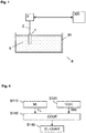
- FIG. 1 illustrates a measuring system with a container 8 comprising a holding vessel 81 filled with a process material 6.
- the properties of the process material 6 are measured by means of at least one measuring probe 1 which is connected through signal-transmitting device 2 to an evaluating device 3.
- the evaluating devices 3, which, among other functions, serve as measurement converters, are coupled to a processing device 300, for example a computer.
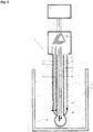
- an electrochemical measuring probe such as for example a pH-measuring probe, which in the configuration of a single rod measuring chain includes a glass electrode 16, a reference electrode 15, and an auxiliary electrode 18, is represented schematically in FIG. 2 .
- the glass electrode with a conductor lead element 16 and the reference electrode with a reference lead element 15 are constructively combined in one unit.
- the conductor lead element 16 is immersed in a solution with a defined pH value, specifically an inner buffer 14, which establishes the electrically conductive connection between the inside of the glass membrane 111 and the conductor lead element 16.
- the reference lead element 15 is immersed in an electrolyte, specifically an outer buffer 13 which, by way of a porous separating wall or diaphragm 121, allows an exchange of electrical charges to take place with the measurement material 6.
- the electrical potentials of the signal source (seen as signal source SQ1 in FIG. 3 ) which during the measurement set themselves up at the conductor lead element 16, at the reference lead element 15, and/or at the auxiliary electrode 18 are measured and then further processed with the signal-processing unit OP, preferably an operational amplifier.
- the signal-processing unit OP preferably an operational amplifier.
- a temperature-measuring sensor 17 is arranged, which provides the possibility to automatically compensate for temperature effects and to register temperature cycles.
- the signal-processing unit OP which will be described in more detail below, is incorporated in the head of the measuring probe 1 and connected by way of signal lead 2 to the evaluating device 3.
- the measuring probe 1 is a solid-state pH sensor comprising an active layer behaving as a voltage source.
- the glass electrode 16 of the measuring probe 1 comprises typically an ion pH sensitive glass substrate and several layers on top of said ion pH sensitive glass substrate.
- the layers may comprise an elementar/lithium layer, a Lithium Phosphorus Oxynitride - generally designed by the acronym LiPON - layer, and a protective layer adapted to limit degradations of the lithium layer as well as to provide a packaging structure for stabilizing the whole glass electrode against environmental influences.
- the electrical potential of the glass electrode 16 of the measuring probe 1 is not null, even when the conductor lead element 16 is not immersed in the holding vessel 81 filled with the process material 6.
- FIG. 3 shows the measuring device of FIG. 2 in an advantageous embodiment with a measuring probe 1 which includes at least one electrode EL, for example a glass electrode and a reference electrode, delivering a measuring signal.
- a measuring probe 1 which includes at least one electrode EL, for example a glass electrode and a reference electrode, delivering a measuring signal.
- an electrode voltage U E may be observed either only when the measuring probe 1 is immersed in the process material 6 or constantly - in the case of use of a solid-state pH sensor, for example.
- the electrode EL itself forms a voltage source SQ1 whose internal resistance is represented in the drawing as the electrode resistance R E .
- the voltage source SQ1 is coupled to a first ground connection GC1.
- the glass membrane of a glass electrode represents a very high resistance, while the transition resistance of the reference electrode results in a relatively low resistance value.
- the electrode resistance R E is dependent on the temperature observed at the measuring probe 1, and becomes very small above 100 degrees Celsius.
- the measuring signal more particularly the electrode voltage U E , is sent for processing to a signal processing unit OP by way of a measuring signal circuit 19.
- the not yet processed, partially processed or fully processed signals are transmitted through a connecting lead 2b to a signal evaluating unit PROC.
- the signal-evaluating unit PROC is incorporated in an evaluating device 3 or a transmitter 3 and can communicate through internal connections with a memory unit MEM and a communication unit COM.
- the processed and/or evaluated measurements can subsequently be passed on to be used for example for the control and monitoring of the process system.
- the evaluating unit 3 or the transmitter TR includes a variety of components such as a communication unit COM, a signal-evaluating unit PROC, and/or a memory unit MEM, which are connected bi-directionally among each other and thus are able to exchange data, instruction or programs.
- the communication unit COM coordinates all activities of the measuring probe 1 and of the evaluating device 3 and establishes the communication to the master computer 300. Through the connection 2a, instructions are transmitted from the communication unit COM to a stimulation controller unit SCU in the measuring probe 1.
- the communication unit COM can also issue instructions to the signal-evaluating unit PROC, receive data from the signal-evaluating unit PROC, or also store data and programs in the memory unit MEM.
- the stimulation controller unit SCU which can also be incorporated in the signal-processing unit OP, functions as a controller element for the switching element S1 by sending control signals through the control output terminals CL1, thereby triggering responses in the switching element S1.
- the switching elements can be configured as mechanical or electronic elements or as semiconductor elements such as transistors. However, the switching operations can also be performed directly with the controller unit CU.
- a test signal SIG such as bipolar pulses
- the test signal SIG can be delivered, by way of a test signal circuit 20, during a verification phase to a coupling element Q2.
- the test signal SIG can be generated by way of a signal source SQ2.
- the test signal SIG is used for example to determine the resistance of the glass electrode 16, as described for example in patent document US 2009/0251152 A1 .
- the coupling element Q2 ensures galvanic isolation between the measuring signal circuit 19 carrying the electrode voltage U E and the test signal circuit 20 carrying the test signal SIG. Consequently, the coupling element Q2 also allows modulating the electrode voltage U E with the test signal SIG.
- the coupling element Q2 is arranged to prevent leakage of current from the test signal circuit 20 to the measurement signal circuit 19.
- the coupling element Q2 is arranged so as that the test signal SIG is fed into an inductive element generating accordingly an electromagnetic field altering the electrode voltage U E .
- the coupling element Q2 may comprise a transformer provided with a primary winding connected between the test signal circuit 20 and a second ground connection GC2 and a secondary winding connected between the measurement signal circuit 19 and the signal-processing unit OP. The primary winding and the secondary winding are not electrically connected, but inductively coupled.
- the coupling element Q2 may comprise mechanical, optical and/or electrical means for ensuring the galvanic isolation between the measurement signal circuit 19 carrying the electrode voltage UE and the test signal circuit 20 carrying the measurement signal SIG.
- Fig. 4 schematically represents a method for determining, during a verification phase, at least one electrical characteristic - for example its resistance - of the sensing element of an electrode. The method comprises the following steps:
Description
- The present disclosure relates to a method and device for monitoring and/or determining the condition of a measuring probe adapted to measure at least one property of a process material, such as for example an ion-sensitive measuring probe, in particular a pH-measuring probe, an oxygen-measuring probe, or a CO2-measuring probe. More particularly, the present disclosure relates to stimulation means, used notably for measuring resistance of a measuring circuit of the measuring probe.
- The monitoring and control of industrial processes, for example in the chemical and pharmaceutical industries, in the textile industry, in the food and beverage industries, in the processing of paper and cellulose, or in the fields of water processing and waste water treatment, is based on the measurement of process variables that are determined by means of suitable measuring probes.
- According to "Process Measurement Solutions Catalog 2005/06", Mettler-Toledo GmbH, CH-8902 Urdorf, Switzerland, , a complete measuring system consists of a housing, a measuring probe, a cable and a measurement converter (also called a transmitter). By means of the housing, the measuring probe is brought into contact with the process that is to be measured or monitored, for example by immersing the probe in the process material and holding it there. The measuring probe serves to measure specific properties of the process. Measurement signals are sent through the cable to the transmitter, which communicates with a process control system and converts the measuring signals into readable data. The measuring probes are selected depending on the process material properties that are to be measured.
- Typically, an electrochemical measuring probe such as for example a pH-measuring probe or an oxygen-measuring probe is subject to a load-dependent wear process which is inherent in the functional principle of the probe and which normally leads to a continuous change of the measurement characteristics of the measuring probe.
- In order to take into consideration the impact of such changes into the accuracy of measurements, it is known from the state if the art to monitor essentials electrical characteristics of the signal measuring circuit of a probe, such as the resistivity. In particular, it is known to feed the signal measuring circuit of a probe with a test signal generated by a stimulation circuit, as disclosed for example in patent document
US 2009/0251152 A1 . For example, for determining the resistance of the signal measuring circuit connected to the pH glass of an electrode, a rectangular impulse signal is switched onto the measuring signal, the resulting combined signal being then passed through electronic filters and like correctors to determine said glass resistance. Condensers, operated in parallel to the measuring signal, come generally in between the stimulation circuit and the signal measuring circuit, to dynamically shape the test signal. - However, in this configuration, leakage currents between the signal measuring circuit and the electrically connected stimulation circuit, cannot be avoided, and may affect accuracy of measurements adversely. This issue is even more relevant for measuring probe delivering weak measuring signal, for example pH measuring probe provided with an electrode with a high pH-glass resistance, typically greater than 1 Gohm.
- To mitigate these problems,
patent document GB 2 333 161 A - That's why there is still a need for improved means for determining, during a verification phase, in a measuring system comprising a measuring probe for use in contact with a process material, at least one electrical characteristic of a sensing element of an electrode included in the measuring probe, adapted to be used with measuring probes delivering weak measurement signal, connected to the measuring signal circuit.
- To that end, according to a first aspect, the present invention concerns a measuring system comprising a measuring probe for use in contact with a process material. The measuring probe may be selected from the group consisting of: a pH-measuring probe, an oxygen-measuring probe and a C02-measuring probe.
- The measuring system comprises an electrode provided with a sensing element arranged so as to deliver a measurement signal into a measurement signal circuit, the electrode voltage being related to at least one property of the process material when the electrode is in contact with the process material.
- The sensing element of the electrode may comprise an active layer behaving as a voltage source, the electrode voltage being not null when the electrode is not in contact with the process material.
- For example, the electrode may comprise a solid-state pH sensor comprising an active layer behaving as a voltage source. The electrode may comprise an ion pH sensitive glass substrate and several layers on top of said ion pH sensitive glass substrate. The layers may comprise an elementar/lithium layer, a Lithium Phosphorus Oxynitride - generally designed by the acronym LiPON - layer, and a protective layer adapted to limit degradations of the lithium layer as well as to provide a packaging structure for stabilizing the whole glass electrode against environmental influences. The electrical potential of the glass electrode of the
measuring probe 1 is not null, even when the glass electrode is not in contact with theprocess material 6. - The measuring system comprises a signal-processing unit adapted to determine a measurement quantity related to the at least one property of the process material during operation of the measuring probe according to the measurement signal.
- The measuring system comprises a signal source configured to deliver, during a verification phase, a test signal into a test signal circuit.
- The test signal can be one signal or a combination of signals from the following non-exhaustive list: pulses, bipolar pulses, rectangular, triangular, sinusoidal, sawtooth.
- The measuring system comprises a coupling element arranged to ensure galvanic isolation between the measurement signal circuit and the test signal circuit.
- Advantageously, the signal-processing unit is configured, during the verification phase, to determine at least one electrical characteristic of the sensing element of the electrode by observing the measurement signal altered by the test signal. The at least one electrical characteristic of the sensing element may be the resistance of the sensing element.
- According to the invention, the test signal circuit and the measurement signal circuit are now galvanically separated circuits. Consequently, it is now possible to provide the measurement quantity related to the at least one property of the process material - for example a pH value - with improved accuracy compared to prior known solutions, since the measuring signal circuit is not affected anymore by leakage currents from the test signal circuit. Also, as electrical separation between the test signal circuit and the measurement signal circuit is achieved, the test signal circuit cannot be influenced anymore by the electrical characteristics of the sensing element of the electrode.
- Moreover, according to the invention, the measuring signal, coming for example from the glass electrode (in the case of a solid-state pH sensor, a voltage typically varying around 3V) is directly altered by the test signal. Therefore, the invention allows determining directly at least one electrical characteristic of the glass electrode - i.e. impedance of the glass electrode on its own, instead of measuring characteristics of the glass electrode and the process material as previously known- i.e. impedance measured between a glass electrode and a reference electrode.
- The disturbance, caused by the test signal circuit into the measuring signal circuit through the coupling element, used for example, to determine the resistance of the glass electrode, no longer influences measurement quantity. It also provides the additional benefit that the electrical characteristic of the sensing element can be determined more quickly.
- In an embodiment, the coupling element is arranged so as that the test signal is fed into an inductive element generating accordingly an electromagnetic field altering the measurement signal in the measurement signal circuit. More particularly, the coupling element may comprise a transformer provided with a primary winding connected between the test signal circuit and a second ground connection, and a secondary winding connected between the measurement signal circuit and the signal-processing unit. The primary winding and the secondary winding being electrically isolated. The effective galvanic isolation ensured by the use of the inductive element is particularly advantageous, since leakage currents are completely removed. The elimination of leakage currents from the test signal circuit affecting the measurement signal circuit is particularly advantageous, since a high level of accuracy in measurements of the at least one electrical characteristic can be achieved, even with measuring systems comprising an electrode provided with a solid-state pH sensor with an active layer behaving as a voltage source. This solution consequently allows obtaining a measuring system, insensitive to the disturbances of the leakage currents from the test signal circuit, and are considerably more efficient compared to known solution using a capacitive element as coupling element between the test signal circuit and the measurement signal circuit which cannot completely prevent leakage currents and consequently cannot ensure an effective galvanic isolation between the test signal circuit and the measurement signal circuit. Using a transformer as a coupling element is also a reliable and cost-effective solution.
- The coupling element may comprise mechanical, optical and/or electrical means for ensuring the galvanic isolation between the measurement signal circuit and the test signal circuit.
- According to a second aspect, the present invention also concerns a method for determining, during a verification phase, in a measuring system comprising a measuring probe for use in contact with a process material, at least one electrical characteristic of a sensing element of an electrode included in the measuring probe. The method is notably adapted to be implemented in the measuring system according to the first aspect. The method comprises the following steps:
- Transmitting into a signal circuit, a measurement signal delivered by the sensing element, the measurement signal being related to at least one property of the process material when the electrode is in contact with the process material;
- Transmitting, during a verification phase, into a test circuit, a test signal;
- Altering the measurement signal with the test signal by ensuring galvanic isolation between the measurement signal circuit and the test signal circuit;
- Determining the at least one electrical characteristic of the sensing element of the electrode, by observing the measurement signal altered by the test signal.
- Details of the disclosed method and device will become apparent from the description of the embodiments which are shown in schematic and simplified representation in the drawings, wherein:
- Fig. 1
- illustrates the principal structure of a system for measuring at least one property of a
process material 6 by means of ameasuring probe 1; - Fig. 2
- schematically illustrates an
electrochemical measuring probe 1 which is immersed in aprocess material 6 and coupled to an evaluatingdevice 3; - Fig. 3
- represents a block diagram of a measuring system comprising a
measuring probe 1 with electrode EL, ameasuring signal circuit 19, atest signal circuit 20, and a coupling element Q2; - Fig. 4
- represents a diagram of steps of a method for determining, during a verification phase, at least one electrical characteristic of a sensing element of an electrode of a measuring probe.
-
FIG. 1 illustrates a measuring system with acontainer 8 comprising aholding vessel 81 filled with aprocess material 6. The properties of theprocess material 6 are measured by means of at least one measuringprobe 1 which is connected through signal-transmittingdevice 2 to an evaluatingdevice 3. The evaluatingdevices 3, which, among other functions, serve as measurement converters, are coupled to aprocessing device 300, for example a computer. - The principal design structure of an electrochemical measuring probe such as for example a pH-measuring probe, which in the configuration of a single rod measuring chain includes a
glass electrode 16, areference electrode 15, and anauxiliary electrode 18, is represented schematically inFIG. 2 . In the measuringprobe 1, the glass electrode with aconductor lead element 16 and the reference electrode with areference lead element 15 are constructively combined in one unit. Inside a first chamber within aninner tube 11 and a thin-walled glass hemisphere orglass membrane 111 adjoining the tube, theconductor lead element 16 is immersed in a solution with a defined pH value, specifically aninner buffer 14, which establishes the electrically conductive connection between the inside of theglass membrane 111 and theconductor lead element 16. Inside anouter tube 12, thereference lead element 15 is immersed in an electrolyte, specifically anouter buffer 13 which, by way of a porous separating wall ordiaphragm 121, allows an exchange of electrical charges to take place with themeasurement material 6. - The electrical potentials of the signal source (seen as signal source SQ1 in
FIG. 3 ) which during the measurement set themselves up at theconductor lead element 16, at thereference lead element 15, and/or at theauxiliary electrode 18 are measured and then further processed with the signal-processing unit OP, preferably an operational amplifier. In the inner buffer space, a temperature-measuringsensor 17 is arranged, which provides the possibility to automatically compensate for temperature effects and to register temperature cycles. The signal-processing unit OP, which will be described in more detail below, is incorporated in the head of the measuringprobe 1 and connected by way ofsignal lead 2 to the evaluatingdevice 3. - In an embodiment, the measuring
probe 1 is a solid-state pH sensor comprising an active layer behaving as a voltage source. Theglass electrode 16 of the measuringprobe 1 comprises typically an ion pH sensitive glass substrate and several layers on top of said ion pH sensitive glass substrate. The layers may comprise an elementar/lithium layer, a Lithium Phosphorus Oxynitride - generally designed by the acronym LiPON - layer, and a protective layer adapted to limit degradations of the lithium layer as well as to provide a packaging structure for stabilizing the whole glass electrode against environmental influences. In this embodiment, the electrical potential of theglass electrode 16 of the measuringprobe 1 is not null, even when theconductor lead element 16 is not immersed in the holdingvessel 81 filled with theprocess material 6. This behaviour is notably due to the electrical characteristics of the elementar/lithium layer and the Lithium Phosphorus Oxynitride layer. As a consequence, the electrical potentials of the signal source (seen as signal source SQ1 inFIG. 3 ) are not null, even when theconductor lead element 16 is not immersed in the holding vessel 81 - for example, the potential observed at theglass electrode 16 is sensibly around -3V when the glass electrode is not in contact with theprocess material 6. -
FIG. 3 shows the measuring device ofFIG. 2 in an advantageous embodiment with a measuringprobe 1 which includes at least one electrode EL, for example a glass electrode and a reference electrode, delivering a measuring signal. Depending on the measuringprobe 1 used, at the electrode EL, an electrode voltage UE may be observed either only when the measuringprobe 1 is immersed in theprocess material 6 or constantly - in the case of use of a solid-state pH sensor, for example. The electrode EL itself forms a voltage source SQ1 whose internal resistance is represented in the drawing as the electrode resistance RE. The voltage source SQ1 is coupled to a first ground connection GC1. For example, the glass membrane of a glass electrode represents a very high resistance, while the transition resistance of the reference electrode results in a relatively low resistance value. However, the electrode resistance RE is dependent on the temperature observed at the measuringprobe 1, and becomes very small above 100 degrees Celsius. - The measuring signal, more particularly the electrode voltage UE, is sent for processing to a signal processing unit OP by way of a measuring
signal circuit 19. Next, the not yet processed, partially processed or fully processed signals are transmitted through a connecting lead 2b to a signal evaluating unit PROC. The signal-evaluating unit PROC is incorporated in an evaluatingdevice 3 or atransmitter 3 and can communicate through internal connections with a memory unit MEM and a communication unit COM. The processed and/or evaluated measurements can subsequently be passed on to be used for example for the control and monitoring of the process system. - The evaluating
unit 3 or the transmitter TR includes a variety of components such as a communication unit COM, a signal-evaluating unit PROC, and/or a memory unit MEM, which are connected bi-directionally among each other and thus are able to exchange data, instruction or programs. - The communication unit COM coordinates all activities of the measuring
probe 1 and of the evaluatingdevice 3 and establishes the communication to themaster computer 300. Through theconnection 2a, instructions are transmitted from the communication unit COM to a stimulation controller unit SCU in the measuringprobe 1. The communication unit COM can also issue instructions to the signal-evaluating unit PROC, receive data from the signal-evaluating unit PROC, or also store data and programs in the memory unit MEM. - The stimulation controller unit SCU, which can also be incorporated in the signal-processing unit OP, functions as a controller element for the switching element S1 by sending control signals through the control output terminals CL1, thereby triggering responses in the switching element S1. The switching elements can be configured as mechanical or electronic elements or as semiconductor elements such as transistors. However, the switching operations can also be performed directly with the controller unit CU.
- By means of the switching element S1, a test signal SIG, such as bipolar pulses, can be delivered, by way of a
test signal circuit 20, during a verification phase to a coupling element Q2. The test signal SIG can be generated by way of a signal source SQ2. The test signal SIG is used for example to determine the resistance of theglass electrode 16, as described for example in patent documentUS 2009/0251152 A1 . - The coupling element Q2 ensures galvanic isolation between the measuring
signal circuit 19 carrying the electrode voltage UE and thetest signal circuit 20 carrying the test signal SIG. Consequently, the coupling element Q2 also allows modulating the electrode voltage UE with the test signal SIG. The coupling element Q2 is arranged to prevent leakage of current from thetest signal circuit 20 to themeasurement signal circuit 19. - In an embodiment, the coupling element Q2 is arranged so as that the test signal SIG is fed into an inductive element generating accordingly an electromagnetic field altering the electrode voltage UE. For example, as illustrated on
Fig. 3 , the coupling element Q2 may comprise a transformer provided with a primary winding connected between thetest signal circuit 20 and a second ground connection GC2 and a secondary winding connected between themeasurement signal circuit 19 and the signal-processing unit OP. The primary winding and the secondary winding are not electrically connected, but inductively coupled. - Alternatively, the coupling element Q2 may comprise mechanical, optical and/or electrical means for ensuring the galvanic isolation between the
measurement signal circuit 19 carrying the electrode voltage UE and thetest signal circuit 20 carrying the measurement signal SIG. -
Fig. 4 schematically represents a method for determining, during a verification phase, at least one electrical characteristic - for example its resistance - of the sensing element of an electrode. The method comprises the following steps: - During a step S110, transmitting, into the signal circuit, a measurement signal delivered by the sensing element, the measurement signal being related to at least one property of the process material when the electrode is in contact with the process material;
- During a step S120,transmitting, during a verification phase, into a test circuit, a test signal;
- During a step S130, altering the measurement signal with the test signal by ensuring galvanic isolation between the measurement signal circuit and the test signal circuit;
- During a step S140, determining the at least one electrical characteristic of the sensing element of the electrode, by observing the measurement signal altered by the test signal.
-
- 1
- measuring probe
- 2
- signal-transmitting device
- 3
- evaluating device
- 6
- measurement material
- 8
- container
- 81
- holding vessel
- 300
- processing device
- 11
- inner tube
- 12
- outer tube
- 13
- outer buffer
- 14
- inner buffer
- 15
- reference electrode
- 16
- glass electrode
- 17
- temperature-measuring sensor
- 18
- auxiliary electrode
- 111
- thin-walled glass hemisphere or glass membrane
- 121
- diaphragm
- 19
- Measurement signal circuit
- 20
- test signal circuit
Claims (8)
- Measuring system (8) comprising a measuring probe (1) for use in contact with a process material (6), comprising:• a measurement signal circuit (19);• a test signal circuit (20);• an electrode (EL) provided with a sensing element arranged so as to deliver a measurement signal into the measurement signal circuit (19), the electrode voltage being related to at least one property of the process material when the electrode is in contact with the process material;• a signal-processing unit (OP) adapted to determine a measurement quantity related to the at least one property of the process material during operation of the measuring probe according to the measurement signal;• a signal source (SQ2) configured to deliver, during a verification phase, a test signal (SIG) into the test signal circuit (20);• a coupling element (Q2) arranged to modulate the electrode voltage UE with the test signal SIG and to ensure galvanic isolation between the measurement signal circuit (19) and the test signal circuit (20).
- Measuring system according to claim 1, wherein the coupling element (Q2) is arranged so as that the test signal (SIG) is fed into an inductive element generating accordingly an electromagnetic field altering the measurement signal in the measurement signal circuit.
- Measuring system according to claim 2, wherein the coupling element (Q2) comprises a transformer provided with:• a primary winding connected between the test signal circuit (20) and a second ground connection (GC2); and,• a secondary winding connected between the measurement signal circuit (19) and the signal-processing unit (OP),
the primary winding and the secondary winding being electrically isolated. - Measuring system according to any one of claims 1 to 3, wherein the signal-processing unit (OP) is configured, during the verification phase, to determine at least one electrical characteristic of the sensing element of the electrode (16) by observing the measurement signal altered by the test signal.
- Measuring system according to any one of the claims 1 to 4, wherein the sensing element of the electrode comprises an active layer behaving as a voltage source, the electrode voltage being not null when the electrode is not in contact with the process material.
- Measuring system according to any one of the claims 1 to 5, wherein the measuring probe is selected from the group consisting of: a pH-measuring probe, an oxygen-measuring probe and a C02-measuring probe.
- Measuring system according to claims 5 and 6, wherein the sensing element of the electrode comprises a Lithium Phosphorus Oxynitride layer.
- Method for determining, during a verification phase, in a measuring system (8) comprising a measuring probe (1) for use in contact with a process material (6), at least one electrical characteristic of a sensing element of an electrode (16) included in the measuring probe (1), comprising the following steps:• Transmitting (S110) into a signal circuit (20), a measurement signal delivered by the sensing element, the measurement signal being related to at least one property of the process material when the electrode is in contact with the process material;• Transmitting (S120), during a verification phase, into a test circuit (20), a test signal (SIG);• Altering (S130) the measurement signal with the test signal (SIG) by ensuring galvanic isolation between the measurement signal circuit and the test signal circuit;• Determining (S140) the at least one electrical characteristic of the sensing element of the electrode, by observing the measurement signal altered by the test signal.
Priority Applications (4)
| Application Number | Priority Date | Filing Date | Title |
|---|---|---|---|
| EP17181636.6A EP3431978B1 (en) | 2017-07-17 | 2017-07-17 | Method and device for monitoring and/or determining the condition of a measuring probe |
| ES17181636T ES2835779T3 (en) | 2017-07-17 | 2017-07-17 | Procedure and device for monitoring and / or determining the status of a measurement probe |
| US16/036,387 US10718736B2 (en) | 2017-07-17 | 2018-07-16 | Method and device for monitoring and/or determining the condition of a measuring probe |
| CN201810783602.7A CN109270149B (en) | 2017-07-17 | 2018-07-17 | Improved method and apparatus for monitoring and/or determining the condition of a measurement probe |
Applications Claiming Priority (1)
| Application Number | Priority Date | Filing Date | Title |
|---|---|---|---|
| EP17181636.6A EP3431978B1 (en) | 2017-07-17 | 2017-07-17 | Method and device for monitoring and/or determining the condition of a measuring probe |
Publications (2)
| Publication Number | Publication Date |
|---|---|
| EP3431978A1 EP3431978A1 (en) | 2019-01-23 |
| EP3431978B1 true EP3431978B1 (en) | 2020-09-02 |
Family
ID=59366262
Family Applications (1)
| Application Number | Title | Priority Date | Filing Date |
|---|---|---|---|
| EP17181636.6A Active EP3431978B1 (en) | 2017-07-17 | 2017-07-17 | Method and device for monitoring and/or determining the condition of a measuring probe |
Country Status (4)
| Country | Link |
|---|---|
| US (1) | US10718736B2 (en) |
| EP (1) | EP3431978B1 (en) |
| CN (1) | CN109270149B (en) |
| ES (1) | ES2835779T3 (en) |
Family Cites Families (15)
| Publication number | Priority date | Publication date | Assignee | Title |
|---|---|---|---|---|
| US3661748A (en) * | 1970-04-07 | 1972-05-09 | Instrumentation Labor Inc | Fault sensing instrumentation |
| AU8868882A (en) * | 1982-09-24 | 1984-03-29 | Petty, J.D. | Electrode monitor |
| EP0354958B1 (en) * | 1987-03-05 | 1994-08-03 | Terumo Kabushiki Kaisha | Apparatus for measuring data of living body |
| US5206540A (en) * | 1991-05-09 | 1993-04-27 | Unitrode Corporation | Transformer isolated drive circuit |
| GB2333161B (en) | 1997-12-24 | 2002-06-12 | Abb Kent Taylor Ltd | Electrode integrity checking |
| DE10055090A1 (en) * | 2000-11-07 | 2002-05-08 | Conducta Endress & Hauser | Plug-in connector for connecting a transmission line to at least one sensor, has arrangement for implementing contactless signal transfer between plug element and socket element |
| DE502004002457D1 (en) * | 2003-04-10 | 2007-02-08 | Laser Optoelektronik Gmbh Z | POWER SUPPLY |
| US7250857B2 (en) * | 2003-08-07 | 2007-07-31 | Simmonds Precision Products, Inc. | Multiplexer method and system for intrinsically safe applications and a multiplexer switch for use therein |
| DE102004063249A1 (en) * | 2004-12-23 | 2006-07-13 | Fraunhofer-Gesellschaft zur Förderung der angewandten Forschung e.V. | Sensor system and method for the capacitive measurement of electromagnetic signals of biological origin |
| FR2910162B1 (en) * | 2006-12-18 | 2009-12-11 | Schneider Electric Ind Sas | ELECTRICALLY INSULATED MEASURING SIGNAL COUPLING DEVICE AND ELECTRICAL APPARATUS COMPRISING SUCH A DEVICE |
| EP1936367A1 (en) | 2006-12-22 | 2008-06-25 | Mettler-Toledo AG | Method and device for monitoring and/or determining the status of a measuring probe |
| US7950264B2 (en) * | 2007-11-30 | 2011-05-31 | Endress + Hauser Conducta Gesellschaft für Mess-und Regeltechnik mbH + Co. KG | Disposable measurement arrangement and method of testing and/or calibrating it |
| EP2224234A4 (en) * | 2007-12-18 | 2015-01-28 | Horiba Ltd G | Ion-selective electrode |
| KR101029873B1 (en) * | 2008-12-05 | 2011-04-18 | 한국과학기술원 | The device of measuring carbon dioxide |
| DE102010044180A1 (en) * | 2010-11-19 | 2012-05-24 | Endress + Hauser Gmbh + Co. Kg | Device for determining and / or monitoring at least one process variable |
-
2017
- 2017-07-17 EP EP17181636.6A patent/EP3431978B1/en active Active
- 2017-07-17 ES ES17181636T patent/ES2835779T3/en active Active
-
2018
- 2018-07-16 US US16/036,387 patent/US10718736B2/en active Active
- 2018-07-17 CN CN201810783602.7A patent/CN109270149B/en active Active
Non-Patent Citations (1)
| Title |
|---|
| None * |
Also Published As
| Publication number | Publication date |
|---|---|
| CN109270149A (en) | 2019-01-25 |
| ES2835779T3 (en) | 2021-06-23 |
| CN109270149B (en) | 2023-04-07 |
| US20190017961A1 (en) | 2019-01-17 |
| US10718736B2 (en) | 2020-07-21 |
| EP3431978A1 (en) | 2019-01-23 |
Similar Documents
| Publication | Publication Date | Title |
|---|---|---|
| US4822456A (en) | Ion measuring apparatus and monitoring system | |
| US20110023586A1 (en) | Water analysis sensor arrangement | |
| EP1456637A2 (en) | A pH SENSOR WITH INTERNAL SOLUTION GROUND | |
| CN104122313B (en) | multiple-electrode ionic probe | |
| US9128035B2 (en) | Sensor for registering an analyte concentration | |
| JP6670432B2 (en) | Integrated ion detection device and method | |
| EP3431978B1 (en) | Method and device for monitoring and/or determining the condition of a measuring probe | |
| JP7353407B2 (en) | Capillary electrophoresis cathode system and method | |
| CN112083052B (en) | Potentiometer probe | |
| US9772300B2 (en) | Inductive conductivity sensor for measuring the specific electrical conductivity of a medium | |
| CN110702748B (en) | Potentiometric sensor assembly and method for monitoring the sensor function of a potentiometric sensor | |
| US20080283399A1 (en) | Potentiometric process analytic sensor with isolated temperature sensor | |
| US11549966B2 (en) | Interface unit for coupling a probe to a measuring system | |
| US20230314360A1 (en) | pH SENSOR WITH BACKUP pH SENSING ELECTRODE | |
| CN219830933U (en) | Electrochemical composite sensor | |
| US11119065B2 (en) | Electromagnetic sensor | |
| US20230314368A1 (en) | pH SENSOR WITH SECONDARY REFERENCE ELECTRODE | |
| US20050040038A1 (en) | Diagnostic electro-chemical reference half cell | |
| JP2009092414A (en) | Ion concentration measuring apparatus | |
| WO2011155815A1 (en) | Reusable miniaturized reference electrode | |
| NO141103B (en) | DEVICE FOR MEASUREMENT OF IONES OR MOLECULAR CONCENTRATIONS |
Legal Events
| Date | Code | Title | Description |
|---|---|---|---|
| PUAI | Public reference made under article 153(3) epc to a published international application that has entered the european phase |
Free format text: ORIGINAL CODE: 0009012 |
|
| STAA | Information on the status of an ep patent application or granted ep patent |
Free format text: STATUS: THE APPLICATION HAS BEEN PUBLISHED |
|
| AK | Designated contracting states |
Kind code of ref document: A1 Designated state(s): AL AT BE BG CH CY CZ DE DK EE ES FI FR GB GR HR HU IE IS IT LI LT LU LV MC MK MT NL NO PL PT RO RS SE SI SK SM TR |
|
| AX | Request for extension of the european patent |
Extension state: BA ME |
|
| STAA | Information on the status of an ep patent application or granted ep patent |
Free format text: STATUS: REQUEST FOR EXAMINATION WAS MADE |
|
| 17P | Request for examination filed |
Effective date: 20190725 |
|
| RBV | Designated contracting states (corrected) |
Designated state(s): AL AT BE BG CH CY CZ DE DK EE ES FI FR GB GR HR HU IE IS IT LI LT LU LV MC MK MT NL NO PL PT RO RS SE SI SK SM TR |
|
| GRAP | Despatch of communication of intention to grant a patent |
Free format text: ORIGINAL CODE: EPIDOSNIGR1 |
|
| STAA | Information on the status of an ep patent application or granted ep patent |
Free format text: STATUS: GRANT OF PATENT IS INTENDED |
|
| INTG | Intention to grant announced |
Effective date: 20200417 |
|
| GRAS | Grant fee paid |
Free format text: ORIGINAL CODE: EPIDOSNIGR3 |
|
| GRAA | (expected) grant |
Free format text: ORIGINAL CODE: 0009210 |
|
| STAA | Information on the status of an ep patent application or granted ep patent |
Free format text: STATUS: THE PATENT HAS BEEN GRANTED |
|
| AK | Designated contracting states |
Kind code of ref document: B1 Designated state(s): AL AT BE BG CH CY CZ DE DK EE ES FI FR GB GR HR HU IE IS IT LI LT LU LV MC MK MT NL NO PL PT RO RS SE SI SK SM TR |
|
| REG | Reference to a national code |
Ref country code: GB Ref legal event code: FG4D |
|
| REG | Reference to a national code |
Ref country code: AT Ref legal event code: REF Ref document number: 1309427 Country of ref document: AT Kind code of ref document: T Effective date: 20200915 Ref country code: CH Ref legal event code: EP |
|
| REG | Reference to a national code |
Ref country code: DE Ref legal event code: R096 Ref document number: 602017022658 Country of ref document: DE |
|
| REG | Reference to a national code |
Ref country code: IE Ref legal event code: FG4D |
|
| REG | Reference to a national code |
Ref country code: NL Ref legal event code: FP |
|
| REG | Reference to a national code |
Ref country code: LT Ref legal event code: MG4D |
|
| PG25 | Lapsed in a contracting state [announced via postgrant information from national office to epo] |
Ref country code: LT Free format text: LAPSE BECAUSE OF FAILURE TO SUBMIT A TRANSLATION OF THE DESCRIPTION OR TO PAY THE FEE WITHIN THE PRESCRIBED TIME-LIMIT Effective date: 20200902 Ref country code: HR Free format text: LAPSE BECAUSE OF FAILURE TO SUBMIT A TRANSLATION OF THE DESCRIPTION OR TO PAY THE FEE WITHIN THE PRESCRIBED TIME-LIMIT Effective date: 20200902 Ref country code: SE Free format text: LAPSE BECAUSE OF FAILURE TO SUBMIT A TRANSLATION OF THE DESCRIPTION OR TO PAY THE FEE WITHIN THE PRESCRIBED TIME-LIMIT Effective date: 20200902 Ref country code: GR Free format text: LAPSE BECAUSE OF FAILURE TO SUBMIT A TRANSLATION OF THE DESCRIPTION OR TO PAY THE FEE WITHIN THE PRESCRIBED TIME-LIMIT Effective date: 20201203 Ref country code: FI Free format text: LAPSE BECAUSE OF FAILURE TO SUBMIT A TRANSLATION OF THE DESCRIPTION OR TO PAY THE FEE WITHIN THE PRESCRIBED TIME-LIMIT Effective date: 20200902 Ref country code: NO Free format text: LAPSE BECAUSE OF FAILURE TO SUBMIT A TRANSLATION OF THE DESCRIPTION OR TO PAY THE FEE WITHIN THE PRESCRIBED TIME-LIMIT Effective date: 20201202 Ref country code: BG Free format text: LAPSE BECAUSE OF FAILURE TO SUBMIT A TRANSLATION OF THE DESCRIPTION OR TO PAY THE FEE WITHIN THE PRESCRIBED TIME-LIMIT Effective date: 20201202 |
|
| REG | Reference to a national code |
Ref country code: AT Ref legal event code: MK05 Ref document number: 1309427 Country of ref document: AT Kind code of ref document: T Effective date: 20200902 |
|
| PG25 | Lapsed in a contracting state [announced via postgrant information from national office to epo] |
Ref country code: PL Free format text: LAPSE BECAUSE OF FAILURE TO SUBMIT A TRANSLATION OF THE DESCRIPTION OR TO PAY THE FEE WITHIN THE PRESCRIBED TIME-LIMIT Effective date: 20200902 Ref country code: RS Free format text: LAPSE BECAUSE OF FAILURE TO SUBMIT A TRANSLATION OF THE DESCRIPTION OR TO PAY THE FEE WITHIN THE PRESCRIBED TIME-LIMIT Effective date: 20200902 Ref country code: LV Free format text: LAPSE BECAUSE OF FAILURE TO SUBMIT A TRANSLATION OF THE DESCRIPTION OR TO PAY THE FEE WITHIN THE PRESCRIBED TIME-LIMIT Effective date: 20200902 |
|
| PG25 | Lapsed in a contracting state [announced via postgrant information from national office to epo] |
Ref country code: CZ Free format text: LAPSE BECAUSE OF FAILURE TO SUBMIT A TRANSLATION OF THE DESCRIPTION OR TO PAY THE FEE WITHIN THE PRESCRIBED TIME-LIMIT Effective date: 20200902 Ref country code: RO Free format text: LAPSE BECAUSE OF FAILURE TO SUBMIT A TRANSLATION OF THE DESCRIPTION OR TO PAY THE FEE WITHIN THE PRESCRIBED TIME-LIMIT Effective date: 20200902 Ref country code: PT Free format text: LAPSE BECAUSE OF FAILURE TO SUBMIT A TRANSLATION OF THE DESCRIPTION OR TO PAY THE FEE WITHIN THE PRESCRIBED TIME-LIMIT Effective date: 20210104 Ref country code: EE Free format text: LAPSE BECAUSE OF FAILURE TO SUBMIT A TRANSLATION OF THE DESCRIPTION OR TO PAY THE FEE WITHIN THE PRESCRIBED TIME-LIMIT Effective date: 20200902 Ref country code: SM Free format text: LAPSE BECAUSE OF FAILURE TO SUBMIT A TRANSLATION OF THE DESCRIPTION OR TO PAY THE FEE WITHIN THE PRESCRIBED TIME-LIMIT Effective date: 20200902 |
|
| PG25 | Lapsed in a contracting state [announced via postgrant information from national office to epo] |
Ref country code: AL Free format text: LAPSE BECAUSE OF FAILURE TO SUBMIT A TRANSLATION OF THE DESCRIPTION OR TO PAY THE FEE WITHIN THE PRESCRIBED TIME-LIMIT Effective date: 20200902 Ref country code: AT Free format text: LAPSE BECAUSE OF FAILURE TO SUBMIT A TRANSLATION OF THE DESCRIPTION OR TO PAY THE FEE WITHIN THE PRESCRIBED TIME-LIMIT Effective date: 20200902 Ref country code: IS Free format text: LAPSE BECAUSE OF FAILURE TO SUBMIT A TRANSLATION OF THE DESCRIPTION OR TO PAY THE FEE WITHIN THE PRESCRIBED TIME-LIMIT Effective date: 20210102 |
|
| REG | Reference to a national code |
Ref country code: DE Ref legal event code: R097 Ref document number: 602017022658 Country of ref document: DE |
|
| REG | Reference to a national code |
Ref country code: ES Ref legal event code: FG2A Ref document number: 2835779 Country of ref document: ES Kind code of ref document: T3 Effective date: 20210623 |
|
| PG25 | Lapsed in a contracting state [announced via postgrant information from national office to epo] |
Ref country code: SK Free format text: LAPSE BECAUSE OF FAILURE TO SUBMIT A TRANSLATION OF THE DESCRIPTION OR TO PAY THE FEE WITHIN THE PRESCRIBED TIME-LIMIT Effective date: 20200902 |
|
| PLBE | No opposition filed within time limit |
Free format text: ORIGINAL CODE: 0009261 |
|
| STAA | Information on the status of an ep patent application or granted ep patent |
Free format text: STATUS: NO OPPOSITION FILED WITHIN TIME LIMIT |
|
| 26N | No opposition filed |
Effective date: 20210603 |
|
| PG25 | Lapsed in a contracting state [announced via postgrant information from national office to epo] |
Ref country code: DK Free format text: LAPSE BECAUSE OF FAILURE TO SUBMIT A TRANSLATION OF THE DESCRIPTION OR TO PAY THE FEE WITHIN THE PRESCRIBED TIME-LIMIT Effective date: 20200902 Ref country code: SI Free format text: LAPSE BECAUSE OF FAILURE TO SUBMIT A TRANSLATION OF THE DESCRIPTION OR TO PAY THE FEE WITHIN THE PRESCRIBED TIME-LIMIT Effective date: 20200902 |
|
| PG25 | Lapsed in a contracting state [announced via postgrant information from national office to epo] |
Ref country code: MC Free format text: LAPSE BECAUSE OF FAILURE TO SUBMIT A TRANSLATION OF THE DESCRIPTION OR TO PAY THE FEE WITHIN THE PRESCRIBED TIME-LIMIT Effective date: 20200902 |
|
| REG | Reference to a national code |
Ref country code: BE Ref legal event code: MM Effective date: 20210731 |
|
| PG25 | Lapsed in a contracting state [announced via postgrant information from national office to epo] |
Ref country code: LU Free format text: LAPSE BECAUSE OF NON-PAYMENT OF DUE FEES Effective date: 20210717 |
|
| PG25 | Lapsed in a contracting state [announced via postgrant information from national office to epo] |
Ref country code: IE Free format text: LAPSE BECAUSE OF NON-PAYMENT OF DUE FEES Effective date: 20210717 Ref country code: BE Free format text: LAPSE BECAUSE OF NON-PAYMENT OF DUE FEES Effective date: 20210731 |
|
| PG25 | Lapsed in a contracting state [announced via postgrant information from national office to epo] |
Ref country code: CY Free format text: LAPSE BECAUSE OF FAILURE TO SUBMIT A TRANSLATION OF THE DESCRIPTION OR TO PAY THE FEE WITHIN THE PRESCRIBED TIME-LIMIT Effective date: 20200902 |
|
| PG25 | Lapsed in a contracting state [announced via postgrant information from national office to epo] |
Ref country code: HU Free format text: LAPSE BECAUSE OF FAILURE TO SUBMIT A TRANSLATION OF THE DESCRIPTION OR TO PAY THE FEE WITHIN THE PRESCRIBED TIME-LIMIT; INVALID AB INITIO Effective date: 20170717 |
|
| PGFP | Annual fee paid to national office [announced via postgrant information from national office to epo] |
Ref country code: NL Payment date: 20230726 Year of fee payment: 7 |
|
| PGFP | Annual fee paid to national office [announced via postgrant information from national office to epo] |
Ref country code: IT Payment date: 20230721 Year of fee payment: 7 Ref country code: GB Payment date: 20230725 Year of fee payment: 7 Ref country code: ES Payment date: 20230816 Year of fee payment: 7 Ref country code: CH Payment date: 20230801 Year of fee payment: 7 |
|
| PGFP | Annual fee paid to national office [announced via postgrant information from national office to epo] |
Ref country code: FR Payment date: 20230725 Year of fee payment: 7 Ref country code: DE Payment date: 20230726 Year of fee payment: 7 |